Article

Effect of Phase Change Material Storage on the Dynamic Performance of a Direct Vapor Generation Solar Organic Rankine Cycle System

1
School of Energy and Power Engineering, Jiangsu University, 301 Xuefu Road, Zhenjiang 212000, China
2
Mechanical Engineering & Design, School of Engineering and Applied Science, Aston University, Birmingham B4 7ET, UK
3
Advanced Manufacturing Research Centre, School of Mechanical and Manufacturing Engineering, Dublin City University, D09 Dublin, Ireland
4
Department of Thermal Science and Energy Engineering, University of Science and Technology of China, 96 Jinzhai Road, Hefei 230027, China
*
Authors to whom correspondence should be addressed.
Energies 2020, 13(22), 5904; https://doi.org/10.3390/en13225904
Submission received: 11 October 2020 / Revised: 6 November 2020 / Accepted: 9 November 2020 / Published: 12 November 2020
(This article belongs to the Special Issue Low-Temperature Thermodynamic Power Cycles)

Abstract

:
Solar energy is a potential source for a thermal power generation system. A direct vapor generation solar organic Rankine cycle system using phase change material storage was analyzed in the present study. The overall system consisted of an arrangement of evacuated flat plate collectors, a phase-change-material-based thermal storage tank, a turbine, a water-cooled condenser, and an organic fluid pump. The MATLAB programming environment was used to develop the thermodynamic model of the whole system. The thermal storage tank was modeled using the finite difference method and the results were validated against experimental work carried out in the past. The hourly weather data of Karachi, Pakistan, was used to carry out the dynamic simulation of the system on a weekly, monthly, and annual basis. The impact of phase change material storage on the enhancement of the overall system performance during the charging and discharging modes was also evaluated. The annual organic Rankine cycle efficiency, system efficiency, and net power output were observed to be 12.16%, 9.38%, and 26.8 kW, respectively. The spring and autumn seasons showed better performance of the phase change material storage system compared to the summer and winter seasons. The rise in working fluid temperature, the fall in phase change material temperature, and the amount of heat stored by the thermal storage were found to be at a maximum in September, while their values became a minimum in February.

Graphical Abstract

1. Introduction

The per capita demand for energy is increasing at a fast pace due to exponential increases in the human population, especially in developing countries. Hence, different countries are looking for different viable options to efficiently harness the available energy sources. Therefore, low-grade heat has also gained importance, along with high-grade heat, in the recent past [1]. Solar thermal energy can be an attractive option and a potential source of low-grade heat [2]. Several researchers used different technologies to harness low-grade heat, such as the Stirling cycle, Kalina cycle [3], trilateral flash cycle [4], Goswami cycle [5], and organic Rankine cycle [6]. The organic Rankine cycle (ORC) is found to be one of the most useful technologies for efficiently converting low-to-medium-grade heat energy into power.
The working principle of both steam and organic Rankine cycles is found to be similar. However, an organic Rankine cycle utilizes organic fluid instead of water having a higher molecular mass and a lower boiling point to carry out the heat transfer across the cycle. Moreover, it is more beneficial than the steam Rankine cycle in terms of having a small system size, which is suitable for remote applications, is feasible for hybrid generation, and has a high efficiency at low ambient temperatures [7]. There are different potential sources that are available to power an organic Rankine cycle system, such as biomass energy, geothermal energy, waste heat, and solar energy. Solar thermal energy is a relatively new and quickly growing source of the ORC system [8,9].
There are two kinds of solar ORC systems reported in the past, namely, an indirect or conventional solar ORC system and a direct vapor generation (DVG) solar ORC system. The conventional or indirect solar ORC system is the one in which heat is transferred from a solar collector to an organic fluid using a heat transfer fluid (HTF) through an intermediate heat exchanger (evaporator). However, in the case of the DVG solar ORC system, the solar collector operates as an evaporator, where heat is being carried out by an organic fluid. Therefore, the indirect solar ORC system requires an extra HTF pump and heat exchanger (evaporator), which not only increases the cost but also decreases the thermal efficiency compared to the DVG solar ORC system [10].
Several researchers have reported on the DVG solar ORC system for power generation in the recent past. The past work on the system consists of both experimental work [11,12] and theoretical studies [13,14,15]. It was found that an HTF-based or indirect solar ORC system is less efficient, more complex, and more costly than the DVG system. Conversely, regulation and control of the indirect system are much easier compared to the DVG system [16]. However, the evaporation process inside the collector tube becomes more complicated for the DVG system. Moreover, a DVG solar ORC system is particularly sensitive to climatic conditions, such as solar radiation and ambient temperature [17].
Solar collectors are the core component of a DVG solar ORC system. They can be divided into two types of collectors, namely non-concentrating and concentrating solar collectors. The concentrating one uses beam solar radiation, while non-concentrating collectors use both diffused and beam solar radiation [18]. The solar collectors in a DVG solar ORC system operate at a high temperature and pressure. Therefore, the collectors designed to operate at a high temperature and pressure are considered to be feasible for DVG applications. Solar collectors, such as compound parabolic concentrators, parabolic trough collectors, and evacuated tube heat pipe collectors can be suitable candidates for a DVG solar ORC system [19,20]. However, an evacuated flat plate collector (EFPC) has been reportedly utilized for DVG applications because of its high efficiency at high operating temperatures and pressures. An EFPC collector can reach a thermal efficiency of up to 50% while operating at 200 °C. This kind of collector is also advantageous because of its non-concentrating and non-tracking nature [21].
Solar radiation has an intermittent nature, which can hinder the power generation process. Therefore, thermal energy storage is generally used to run the smooth operation of the DVG solar ORC system [22,23]. There are two types of storage that were reported in the past, namely, latent heat thermal storage (LTS) and sensible thermal storage (STS). A phase change material (PCM) storage is a kind of LTS. It is commonly utilized as a heat storage medium in the DVG solar ORC system. It can store 5–14 times extra heat per unit volume in comparison with an STS [24]. However, there are some disadvantages associated with PCM storage, such as low thermal conductivity, sub-cooling, and flammability [25]. PCM storage can be further subdivided based on its melting point temperature, such as high-temperature PCMs (>150 °C), medium-temperature PCMs (60–150 °C), and low-temperature PCMs (<60 °C). The operating temperature of a DVG solar ORC system lies in the range of 80–150 °C. Hence, these medium-temperature PCMs are found to be feasible for a DVG solar ORC system [26].
The coupling of a solar ORC system with phase change material storage has received significant attention in the recent past. The modeling and simulation of a solar ORC system integrated with PCM storage was performed by Manfrida et al. [27] and Sagar et al. [28]. The simulation periods for the first and second study were selected to be 7 and 10 days, respectively. The first study concluded that the longer length and smaller diameter of a PCM storage tank can significantly improve the overall system performance. However, the second study found that the PCM storage tank achieved a 10% higher efficiency during the charging mode in comparison with discharging mode. A two-staged PCM-based solar ORC system was analyzed by Gang et al. [18]. It was found that the employment of two-staged PCMs significantly increased the heat transfer between the PCM and the working fluid. Moreover, the collector and cycle efficiencies were also evaluated under different operating conditions.
A performance evaluation of the solar ORC system utilizing different types of PCMs was carried out by Freeman et al. [29] and Iasiello et al. [30]. Organic PCMs, inorganic PCMs, and water storage were compared and analyzed in the first study. The results indicated that the solar ORC system based on PCM storage can produce 20% extra electrical power compared to the water-storage-based solar ORC system. The second study was focused on thermal analysis and a comparison of two PCMs, namely erythritol and MgCl2·6H2O. It was found that erythritol could store 30% extra energy per unit volume compared to MgCl2·6H2O.
A solar ORC system having a thermal capacity of 100 kW while using solar salt as a phase change material storage was analyzed [31,32]. It was concluded that the application of aluminum fins resulted in a significant decrease in the temperature gradient across the PCM storage tank. Alvi et al. [22,33] compared and analyzed a PCM-based DVG and indirect solar ORC systems. It was found that the thermal match between the PCM and the working fluid was much stronger than that between water and PCM. However, the energy stored per unit volume in the indirect solar ORC system was more abundant than the DVG solar ORC system.
Most of the previous studies on PCM-based solar ORC systems were concentrated on an indirect or conventional solar ORC system. However, to the best of the authors’ knowledge, detailed research on the impact of phase change material storage on the dynamic performance of a DVG solar ORC system has not yet been analyzed. For the first time, this study analyzed how much the ORC efficiency, overall system efficiency, and net power output was increased by employing PCM storage in a direct vapor generation solar ORC system. The other contributions include
  • A PCM storage tank model development and its validation using the finite difference method in the MATLAB programming environment.
  • The dynamic simulation of a PCM-coupled DVG solar ORC storage system on a weekly, monthly, and annual basis.
  • The evaluation of the fall in working fluid temperatures and rise in PCM temperatures and the quantity of energy stored and released by the PCM during the charging and discharging process.

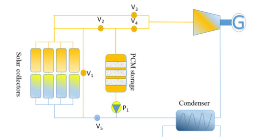
2. System Description and Control

Figure 1 depicts the schematic diagram of the present DVG solar ORC system integrated with a PCM storage tank. The performance of the system was evaluated by utilizing hourly weather data. The present system was made up of an arrangement of EFPC solar thermal collectors, a PCM storage tank, a turbine coupled with a generator, a water-cooled condenser, control valves, and an organic fluid pump. The proposed system was selected because of its lower complexity and simple control. The PCM storage tank operates in two modes, namely, a charging and discharging mode. Moreover, due to the lower complexity and simple control, a basic DVG solar ORC system was selected for the present study.
The system worked in two modes of operation:
  • If the melting point temperature of the PCM was kept lower than the evaporation temperature of the working fluid, then the system lay in charging mode (Tevp > Tm).
  • If the melting point temperature of the PCM was kept higher than the evaporation temperature of the working fluid, then the system lay in discharging mode (Tevp < Tm).
The complete cycle comprised four consecutive operations, namely, evaporation, expansion, condensation, and pressurization. An array of EFPC collectors was utilized to heat the working fluid to a specified evaporation temperature. The working fluid then passed through to the PCM storage tank to either provide or extract heat during the charging or discharging modes, respectively; then, the working fluid in the saturated vapor phase entered the turbine to deliver power. Thereafter, it passed through a condenser to make it condense during the subcooled liquid phase. In the end, it entered a working fluid pump to pressurize it and transfer it back to the solar collectors.
The initial temperature of the PCM was assumed to be 10 °C lower than the PCM melting point temperature. This depicts that the PCM was not charged and it lay in the solid region at the start of the simulation process. The PCM storage tank was allowed to discharge to 20 °C below its melting point temperature. This depicts that the PCM was permitted to discharge in the sensible heat region. Moreover, the discharging continued directly after a charging process. It was presumed that the working fluid passing through the tube remained at a constant temperature. Hence, there was a negligible temperature drop across the tube. Therefore, an isothermal wall boundary condition was selected for the inner surface of the tube. The outer surface of the working fluid tube was part of an interface with the PCM. Therefore, a coupled boundary condition was also selected that represented the change in the outer surface temperature with the PCM. All five valves that were employed in the system opened and closed depending upon whether the charging or discharging mode was activated. The valves V2, V3, and V5 remained opened, while V1 and V4 were closed during the charging mode. However, V4 remained open during the discharging mode and all other valves were closed.
Typical meteorological year (TMY) data for Karachi City in Pakistan was used to carry out the simulation process. The TMY data was obtained using Meteonorm software and was imported into the MATLAB model. Figure 2 presents the monthly average ambient temperature and solar radiation data that was available. The month of June was found to be the hottest month, while January was observed to be the coldest month due to the maximum and minimum solar radiation and ambient temperature, respectively.

3. Thermodynamic Modeling

3.1. The Solar Radiation Collection System

To efficiently harness the available solar radiation, an EFPC array was employed in the DVG solar ORC system. This type of collector is beneficial for areas with less solar resources because it utilizes both beam and diffused solar radiations. Furthermore, it can work efficiently at high operating temperatures and can withstand high operating pressures. Moreover, it is a non-concentrating and non-tracking solar collector with minimal control requirements [21]. The heat loss formula is commonly used to derive the efficiency of a solar thermal collector:
η c l ( T ) = η c l , 0 A G ( T T a m b ) B G ( T T a m b ) 2
where the optical efficiency η c l , o is 0.774, the primary heat loss coefficient A of solar collectors is 0.376 Wm−2 °C−1, and the secondary heat loss coefficient B is 0.006 Wm−2 °C−2 [29,34]. For the instantaneous efficiency, a standard value of the irradiance shell in the tube heat exchanger of 1000 W/m2 was chosen in the present study. The heat loss equation is suitable for the efficiency calculation of a single unit of a solar thermal collector with a surface area of 1–2 m2. However, presuming hundreds and thousands of units, the temperature difference in neighboring collectors was small. Hence, the average temperature of the collector varied from one unit to the next. The organic fluid went into the collector array in the liquid phase, while it existed in the array in the binary or vapor phase. Therefore, it was appropriate to compute the collector’s efficiency in the binary phase by using a heat loss formula because the temperature remained constant during the binary phase. Conversely, the average temperature of the collector varied significantly during the liquid phase. Hence, the thermal efficiency of the solar collector during the liquid phase was computed as follows.
The surface area of the solar thermal collector in the liquid phase was computed using Equation (2) [13]:
S l = T f , i T f , o m f C p , f ( T ) η c l ( T ) G d T
The specific heat of an organic fluid was computed by using the first-order approximation:
C p ( T ) = C p , 0 + α ( T T 0 )
By substituting in a1 = A/G and a2 = B/G, the solar collector area was computed by using Equations (1)–(3):
S l = m f c 2 G ( θ 2 θ 1 ) [ ( C p , 0 + α θ 1 ) ln ( T f , o T a m b θ 1 ) T f , i T a m b θ 1 + ( C p , 0 + α θ 2 ) ln θ 2 T f , i + T a m b θ 2 T f , o + T a m b ]
where the arithmetic solutions were depicted by θ 1 and θ 2 in Equation (4) such that θ 1 < 0 ,    θ 2 > 0 :
η o a 1 θ a 2 θ 2 = 0
C p , a = C p , 0 + α ( T a m b T 0 )
η c l , l = m f ( h l , o h l , i ) G S l
The solar collectors’ efficiency when using an organic fluid in the vapor phase and the thermal efficiency of the overall collector array was computed using Equations (8) and (10), respectively:
η c l , v = η c l , 0 a 1 ( T e v p T a m b ) a 2 ( T e v p T a m b ) 2
S b = m f ( h b , o h b , i ) G × η c l , v
η c l = m f ( h b , o h l , i ) G ( S l + S b )

3.2. Heat Storage System

A shell in the tube heat exchanger that was filled with PCM was selected as a thermal storage tank, as shown in Figure 3. The heat storage tank was of cylindrical shape and consisted of multiple tubes. The bigger tube had a 10 times larger diameter than a mini-tube but its length was equal to the mini-tube. There was a mini-tube inside each tube. The larger diameter tube was filled with PCM, while the working fluid passed through the mini-tube [33]. The outside wall of the heat storage tank was presumed to be insulated. The heat storage tank worked in both charging and discharging modes based on operating and boundary conditions. Energy was delivered from the working fluid to the PCM during the charging mode. Conversely, the PCM released energy to the working fluid during the discharging mode. A famous enthalpy method was employed to carry out the thermodynamic modeling of the PCM storage tank [35,36]. To compute the flow of heat within the heat storage tank, few assumptions were made while developing the heat storage model, as follows:
  • It was assumed that conduction was the major method of heat transfer within the PCM.
  • The current study only considered one-dimensional heat transfer.
  • It was also assumed that the thermo-physical properties of the PCM remained constant during each phase.
  • Natural convection that can happen due to density differences was neglected in the present model.
ρ H t = κ   p c m 2 T p c m y 2
The sensible heat of the PCM was computed using Equation (12):
h ( T ) = T m T ρ p c m C p c m d T p c m
The total enthalpy of the PCM was calculated by combining Equations (11) and (12):
H = { ρ p c m C p c m ( T p c m T m ) f o r    T p c m < T m    S o l i d   r e g i o n ρ p c m C p c m ( T p c m T m ) + λ ρ p c m f o r    T p c m > T m    L i q u i d   r e g i o n
Equation (12) shows that if the PCM was lying in a solid region, it exclusively stored sensible heat. However, if the PCM lay in the liquid region, it stored both sensible and latent heat. The volumetric enthalpy of the PCM was used to derive the temperature of the PCM “Tpcm,” as presented in Equation (14):
T p c m = { T m + H ρ p c m · C p c m f o r    T p c m < T m    S o l i d   r e g i o n T m f o r    T p c m = T m    M u s h y   r e g i o n T m + H ( ρ p c m · λ ) ρ p c m · C p c m f o r    T p c m > T m    L i q u i d   r e g i o n
where the latent heat of the PCM is represented by λ, while ρpcm depicts the density of the PCM. Furthermore, the quantity of heat stored by the PCM storage tank during the charging process was computed by multiplying the total mass of the PCM “Mpcm” by the difference in the maximum and minimum specific enthalpies of the PCM storage tank, as depicted in Equation (15):
Q s t = M p c m ( h m x h m i n )      f o r    T p c m > T m    L i q u i d   r e g i o n
Similarly, the quantity of heat released during the discharging process was computed by multiplying the difference in the maximum and minimum specific enthalpies of the PCM storage tank by the total mass of the PCM “Mpcm,” as shown in Equation (16):
Q r e l = M p c m ( h m x h m i n )      f o r    T p c m < T m    S o l i d   r e g i o n
The total mass of the PCM was calculated by using Equation (17):
M p c m = π ( r p c m 2 r f l u i d 2 ) × L p c m × ρ p c m
where r is the radius, L is the length, and ρ is the density. A commercially available, medium-temperature PCM that is feasible for use in a solar organic Rankine cycle system was selected for this study [37]. The thermo-physical properties of the PCM employed in the present study are shown in Table 1. Mg(NO3)2·6H2O was selected as the storage material in the current study because of its suitable melting point temperature, low cost, low volume changes, and no flammability.

3.3. Validation of the Current Model of the PCM

The current numerical model was validated by comparing its numerical simulation results with the experimental results of Lacriox [38]. The storage unit comprised two concentric tubes with a diameter of 0.0127 m and 0.0258 m, respectively. Both tubes had an equal length of 1 m. The outside tube was well insulated. The space between the tubes was filled with the PCM. The water was employed as an HTF and circulated through the inner tube. The heat transfer fluid mass flow rate was kept at 0.0315 kg/s. The melting point temperature of the PCM (n-octadecane) used was 28.2 °C. To validate, the experimental results were reproduced using the present numerical simulation model. The results were reproduced for a case when the HTF and PCM temperatures were taken at the length of the tube = 1.0. The maximum error between the simulation results and the experimental data of Lacriox [38] was found to be 4.1% by using error analysis. Therefore, this verified the correctness and reliability of the current numerical model, as shown in Figure 4. The thermo-physical properties of the n-octadecane PCM are listed in Table 2.

3.4. The Basic Organic Rankine Cycle

A basic organic Rankine cycle system was considered in this study owing to its lower complexity, low cost, and suitability for low-to-medium temperature applications. The evaporation and condensation processes were assumed to be isobaric, while the expansion and pressurization processes were assumed to be adiabatic. A few assumptions were made for the operating conditions of the basic cycle, as listed in Table 3.
The power generated by the expander and power consumed by the pump was evaluated by using Equations (18) and (19), respectively:
w t = m f ( h t , i h t , o )
w p = m f ( h p , o h p , i )
The isentropic efficiency of the expander and the pump were calculated by using Equations (20) and (21), respectively:
ε t = h t , i h t , o h t , i h t , o s
ε p = h p , o s h p , i h p , o h p , i
where the ideal thermodynamic process is represented by the os subscript. The quantity of energy utilized in the heating process of the ORC was computed by multiplying the mass flow rate of the organic fluid by the rise in the enthalpy of the working fluid when moving from the pump to the expander:
q = m f ( h t , i h p , o )
Finally, the ORC efficiency was computed by dividing the net power output by the quantity of heat supplied, as shown in Equation (23):
η O R C = w t ε g w p q
The overall system efficiency of the DVG solar ORC system was computed as follows:
η s y s = η O R C η c l

4. Results and Discussion

In this section, first, the results of the average daily dynamic performance over a week of the DVG solar ORC system while using Mg(NO3)2·6H2O as a PCM are presented. The weather data of Karachi city in Pakistan, with coordinates of 24.8607° N, 67.0011° E were acquired using Meteonorm software and were included in the MATLAB model to carry out the simulation process. The hottest week of the year was simulated to check the performance of the PCM storage tank and the whole system.
Second, the overall system performance was analyzed and evaluated for the whole year. The results of the variation in the solar collector efficiency, the ORC efficiency, overall system efficiency, and the net power output of the system were analyzed and the results are discussed. Moreover, the fall in the temperature of PCM, the rise in the fluid temperature, the rise in the ORC efficiency, the rise in the system efficiency, and the rise in net power output were also analyzed.

4.1. The Dynamic Performance of the PCM-Based DVG Solar ORC System During the Hottest Week

4.1.1. Variation in the Phase Change Material Temperature and Solar Radiation with Time

To check the dynamic performance of the storage tank, Mg(NO3)2·6H2O was selected as the storage material. The performance of the system was analyzed during the hottest week of the year (the second week of June). Figure 5 shows the change in PCM temperature and solar radiation with time. A 1 h time step was chosen for the complete simulation process. The initial temperature of the PCM was selected to be 10 °C lower than the melting point of the PCM. In the beginning, the PCM temperature decreased till 8:00 a.m., then it increased till 4:00 p.m., and decreased again till midnight. Moreover, it was found that PCM storage was enough to run the system for the whole day.
The PCM temperature varied with a varying inlet temperature of the HTF (working fluid). The working fluid temperature varied with varying climatic conditions. The initial temperature of the PCM was kept 10 °C lower than the melting point temperature of the PCM. At night, there was no solar radiation. Hence, the PCM storage was discharged and the temperature started to decrease until 8:00 a.m. Afterward, the working fluid temperature started increasing due to an increase in solar radiation. Therefore, it started charging the PCM until it reached the melting point temperature. The average temperature of the PCM, which included both the latent and sensible heat, is presented in Figure 5.

4.1.2. Variation in the Collector and ORC Efficiencies with Time

The average daily performance of the PCM-based DVG solar ORC system over a week was analyzed. Figure 6 presents the change in the collector and ORC efficiencies with time. It was found that the ORC efficiency remained in the range of 9.8 to 12%. However, the solar collector efficiency remained in the range of 48 to 75%. Hence, the solar ORC system worked well over 24 h.

4.2. The Performance of the PCM-Based DVG Solar ORC System During the Whole Year

4.2.1. The Change in the ORC and Collector Efficiencies

The collector efficiency represents the performance of the EFPC collector array, while the ORC efficiency represents the efficiency of the whole proposed cycle. Figure 7 shows the daily average change in the collector and ORC efficiencies of the PCM-based DVG solar ORC system for each month over a year. It was found that both parameters (the ORC and collector efficiencies) changed with the change in ambient temperature and solar radiation. Therefore, the aforementioned parameters were directly impacted by the weather pattern of the selected location. The maximum values of the ORC and collector efficiencies were found in June, which was the hottest month of the year, while the minimum values were observed in January, which was the coldest month of the year. The daily average collector and ORC efficiencies over the whole year were found to be 76.9 and 12.1%, respectively. The system performance in terms of the collector and cycle efficiencies was found to be at a maximum in summer, while its value was at a minimum in winter.

4.2.2. The Changes in the System Efficiency and Net Power Output

The overall performance of the solar ORC system was depicted by the system’s efficiency. It was the product of the ORC and collector efficiencies. Moreover, the net power output was computed using the difference between the power generated by the turbine and that consumed by the pump. Figure 8 depicts the change in the daily average system efficiency and net power output of the PCM based-DVG solar ORC system for each month. It was found that both parameters (system efficiency and net power output) increased and decreased with the changes in climatic conditions (ambient temperature and solar radiation). The trend shown by both parameters (system efficiency and net power output) was observed to be similar to the collector and ORC efficiencies. The maximum and minimum values of the system efficiency and net power output was found in June and January, respectively. The average daily system efficiency and net power output for each month throughout the year were observed to be 9.31% and 2.68 kW, respectively. The system performance in terms of the system efficiency and net power output was observed to be at a maximum in summer, while its value was at a minimum in winter.

4.2.3. The Change in the Quantity of Energy Stored by the PCM

The amount of energy stored is one of the core criteria used to assess the performance of PCM storage. The thermal storage tank was designed to work at the melting point temperature of the PCM. However, the total quantity of the energy stored by the PCM includes both latent and sensible heat of the PCM. Figure 9 represents the average daily quantity of energy stored by the PCM in the PCM-based DVG solar ORC system for each month throughout the year. In contrast to the collector, ORC, and system efficiencies, the quantity of energy stored by the PCM did not increase or decrease with the rise and fall in ambient temperature and solar radiation. There was no energy stored in December and January because the solar radiation was very low in these months. There was no heat exchange between the working fluid and PCM because the temperature of the working fluid did not reach above the PCM temperature during these months.
The solar radiation and heat available were at a maximum in June but the quantity of the heat stored by the PCM is very low. This happened because when the ambient temperature and solar radiation were very high, the evaporation temperature of the working fluid reached near to its critical point temperature. At this point, when the evaporation temperature of the working fluid reached near to its critical point temperature, the thermal conductivity of the working fluid decreased significantly, which further impacted the heat exchange between the working fluid and the PCM. For example, the thermal conductivity of R123 at the evaporation temperature of 100 °C and 2 MPa pressure was 0.068 W m−1 K−1, while its value became 0.0205 W m−1 K−1 as the evaporation temperature rose to 180 °C. Hence, the thermal conductivity of R123 more than tripled when its evaporation increased from 100 to 180 °C (near to its critical point temperature, which is 183.68 °C). Therefore, the heat exchange between R123 and the PCM decreased significantly, which further resulted in less energy stored.

4.2.4. The Fall in the Working Fluid Temperature and the Rise in the PCM Temperature

The rise in the PCM temperature gives an idea about the energy stored, while the fall in the working fluid temperature explains the amount of heat released. Figure 10 presents the average daily fall in the working fluid temperature and the rise in the PCM temperature of the PCM-based DVG solar ORC system for each month throughout the year. Both parameters (the fall in the working fluid temperature and the rise in the PCM temperature) displayed similar behaviors as those shown by the energy stored by the PCM. No fall in the working fluid temperature and no rise in the PCM temperature was seen in December or January. The maximum value of both parameters was found to be in the spring and autumn months; their value became less during the summer and winter months. The average daily fall in the working fluid temperature and rise in the PCM temperature throughout the year were found to be 7.69 and 0.75 °C, respectively.

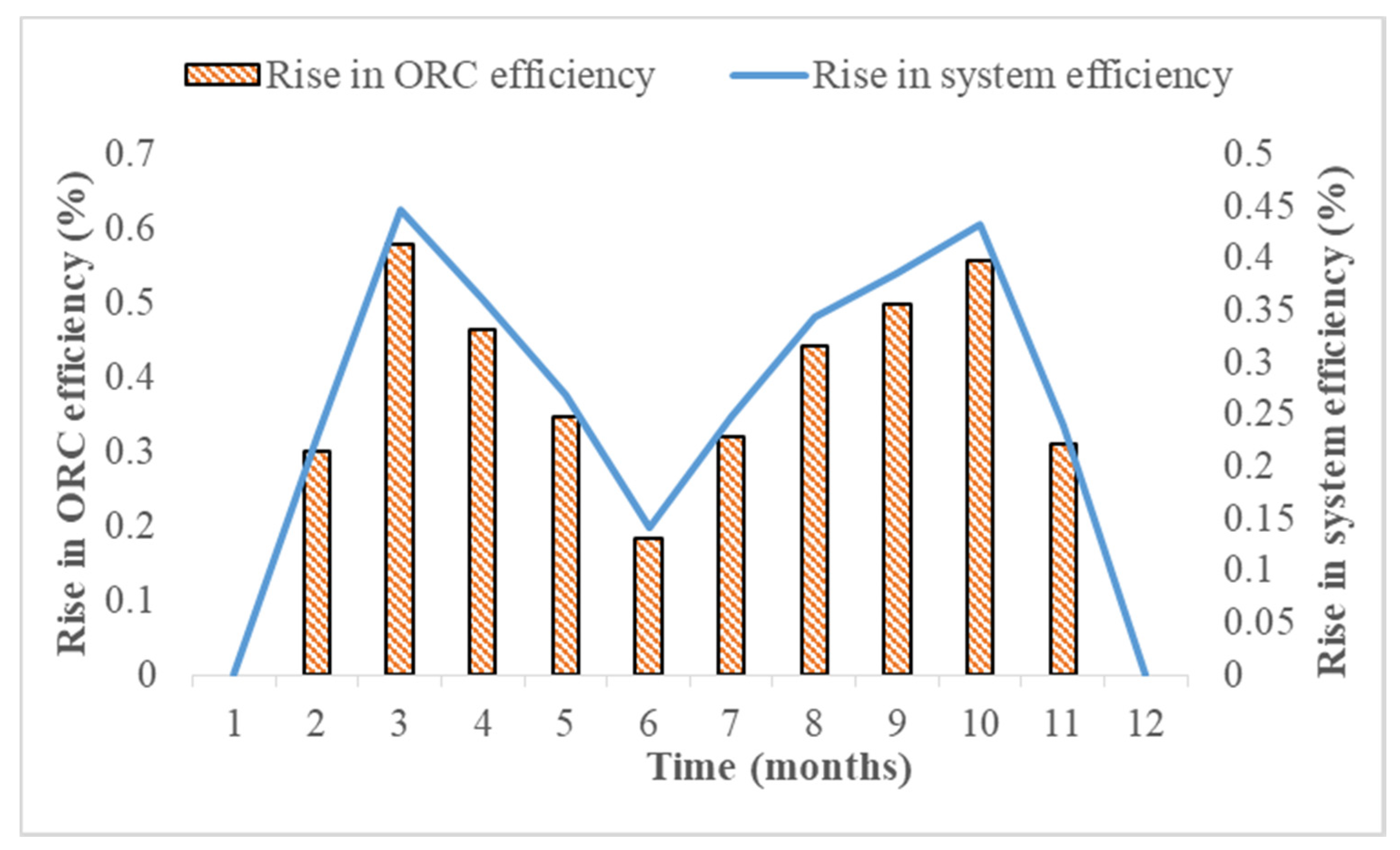
4.3. The Performance Enhancement in the DVG Solar ORC System by Employing the PCM Storage

4.3.1. The Rise in the ORC and System Efficiencies by Employing the PCM Storage

The employment of a PCM storage tank can significantly improve the cycle and overall system efficiencies. Figure 11 shows the average daily rise in the ORC and system efficiencies due to employing a PCM storage tank for each month throughout the year. The two parameters (rise in the ORC and system efficiencies) had a similar trend as that shown by the rise in the PCM temperature, fall in the working fluid temperature, and quantity of the heat stored by the PCM. The maximum increase was seen in the spring and autumn months, while the minimum increase was achieved in the summer and winter months. The rise in the ORC and system efficiencies was less in summer due to the lower heat exchange between the working fluid and the PCM due to a decrease in the thermal conductivity of the working fluid. Moreover, both parameters showed lower increases in the winter months due to the low ambient temperatures and low solar radiation, which further resulted in a minimal rise in the evaporation temperature of the working fluid. Moreover, there was no rise in the ORC and system efficiencies in December and January due to the minimum solar radiation and ambient temperature.

4.3.2. The Rise in the Net Power Output by Employing the PCM Storage

The net power output is also an important parameter that is used to describe the performance of a power generation system. Moreover, the net power output can be increased by employing PCM storage in a DVG solar ORC system. The variation in the average daily rise in the net power output by employing PCM storage in the DVG solar ORC system for each month throughout the year is presented in Figure 12. It was observed that the rise in the net power output followed a similar trend as that shown by the rise in the PCM temperature, the fall in the working fluid temperature, and the amount of energy stored by the PCM. No rise in the power output was seen in December and January due to the minimum solar radiation and ambient temperature. However, the maximum rise in power output was seen during the months of spring and autumn. The rise in the net power output by employing PCM storage increased from 0 to 1.73 kW.

5. Conclusions

A phase-change-material-based direct vapor generation solar ORC system was considered in this study. An array of evacuated flat plate collectors was used to transmit heat to the system. The PCM storage tank was coupled with the system for power generation stability. The whole system was modeled in the MATLAB program to simulate the charging and discharging modes. The simulation time step was kept at 1 hour during the whole simulation process. Weekly, monthly, and annual dynamic simulations were carried out to evaluate the performance of the PCM-based DVG solar ORC system.
Weather data from Karachi city was imported into the MATLAB model that was obtained by using Meteonorm software. First, the collector, ORC, and system efficiencies were evaluated on an average daily basis. Second, the net power output, rise in the PCM temperature, fall in the working fluid temperature, and amount of energy stored by the PCM were analyzed and evaluated. Finally, the rise in the ORC efficiency, system efficiency, and net power output by employing the PCM were evaluated. The collector efficiency was found to be in the range of 75.5% to 76%, the ORC efficiency was observed to lie in the range of 8.78 to 14.4%, and the system efficiency was seen to be in the range of 6.05 to 11.2%. Moreover, the net power output was found to be 17.4 to 33.3 kW, the fall in the working fluid was seen to be in the range of 0 to 9.7 °C, the rise in the PCM temperature was observed to lie in the range of 0 to 0.93 °C, and the amount of energy stored by the PCM was found to be in the range of 0 to 23.7 TJ.
In summary, under the given operating and boundary conditions, the ORC efficiency, system efficiency, and net power output could rise by 0.57%, 0.44%, and 1.73 kW, respectively. Hence, by employing a more complex control strategy, an enhancement in system performance could be further increased by employing PCM storage.

Author Contributions

Conceptualization, J.Z.A.; methodology, J.Z.A., L.A.K., and M.I.; writing—original draft preparation, J.Z.A., G.P., and M.I.; revision and final editing, Y.F. and Q.W. All authors have read and agreed to the published version of the manuscript.

Funding

This research work was supported by the National Natural Science Foundation of China (51806081 and 51876083); the Natural Science Foundation of Jiangsu Province (BK20180882); the Key Research and Development Program of Jiangsu Province, China (BE2019009-4); the Natural Science Foundation of Jiangsu Province (BK20180882); the Key Research and Development Program of Zhenjiang City, China (SH2019008); the Key Project of Taizhou New Energy Research Institute, Jiangsu University, China (2018-20).

Conflicts of Interest

The authors declare no conflict of interest.

Nomenclature

Symbols
APrimary heat loss coefficient of the collector
BSecondary heat loss coefficient of the collector
CHeat capacity (kJ/kg·K)
GSolar irradiance (W/m2)
HVolumetric enthalpy of the PCM (kJ/m3)
hSpecific enthalpy (kJ/kg)
MMass of the PCM (kg)
mMass flow rate (kg/s)
QQuantity of heat (kJ)
qSpecific heat (kJ/kg)
SSurface area of the collector (m2)
TTemperature of the collector (°C)
wSpecific work (kJ/kg)
Greek Symbols
α Heat capacity coefficient, (J/°C)
ε Mechanical efficiency
η Thermal efficiency
ρ Density, (kg/m3)
Partial change
κ Thermal conductivity, (W/m·K)
θ Arithmetic solution, (°C)
λ Latent heat of the PCM, (J)
Abbreviations
GGenerator
PPump
VValve
DVGDirect vapor generation
EFPCEvacuated flat plate collector
HTFHeat transfer fluid
ORCOrganic Rankine cycle
LTSLatent heat thermal storages
STSSensible thermal storage
PCMPhase change material
TMYTypical meteorological year
Subscripts/Superscript
ambAmbient
bBinary
cCritical
clCollector
condCondensation
eExpander
evpEvaporation
fFluid
gGenerator
iInlet
lLiquid
oOutlet
0Reference state
osIdeal state
mMelting point
mxMaximum
minMinimum
ORCOrganic Rankine cycle
pPower
PCMPhase change material
sysSystem
stStored
tTurbine
relReleased

References

  1. Pina, E.A.; Serra, L.M.; Lozano, M.A.; Hernández, A.; Lázaro, A. Comparative Analysis and Design of a Solar-Based Parabolic Trough-ORC Cogeneration Plant for a Commercial Center. Energies 2020, 13, 4807. [Google Scholar] [CrossRef]
  2. Renno, C.; Petito, F.; D’Agostino, D.; Minichiello, F. Modeling of a CPV/T-ORC combined system adopted for an industrial user. Energies 2020, 13, 3476. [Google Scholar] [CrossRef]
  3. Ghaebi, H.; Rostamzadeh, H. Performance comparison of two new cogeneration systems for freshwater and power production based on organic Rankine and Kalina cycles driven by salinity-gradient solar pond. Renew. Energy 2020, 156, 748–767. [Google Scholar] [CrossRef]
  4. Iqbal, M.A.; Rana, S.; Ahmadi, M.; Date, A.; Akbarzadeh, A. Experimental study on the prospect of low-temperature heat to power generation using Trilateral Flash Cycle (TFC). Appl. Therm. Eng. 2020, 172, 115139. [Google Scholar] [CrossRef]
  5. Sayyaadi, H.; Khosravanifard, Y.; Sohani, A. Solutions for thermal energy exploitation from the exhaust of an industrial gas turbine using optimized bottoming cycles. Energy Convers. Manag. 2020, 207, 112523. [Google Scholar] [CrossRef]
  6. Li, J.; Alvi, J.Z.; Pei, G.; Su, Y.; Li, P.; Gao, G.; Ji, J. Modelling of organic Rankine cycle efficiency with respect to the equivalent hot side temperature. Energy 2016, 115, 668–683. [Google Scholar] [CrossRef] [Green Version]
  7. Usman, M.; Imran, M.; Yang, Y.; Lee, D.H.; Park, B.S. Thermo-economic comparison of air-cooled and cooling tower based Organic Rankine Cycle (ORC) with R245fa and R1233zde as candidate working fluids for different geographical climate conditions. Energy 2017, 123, 353–366. [Google Scholar] [CrossRef]
  8. Oyekale, J.; Petrollese, M.; Cau, G. Multi-objective thermo-economic optimization of biomass retrofit for an existing solar organic Rankine cycle power plant based on NSGA-II. Energy Rep. 2020, 6, 136–145. [Google Scholar] [CrossRef]
  9. Refiei, A.; Loni, R.; Najafi, G.; Sahin, A.Z.; Bellos, E. Effect of use of MWCNT/oil nanofluid on the performance of solar organic Rankine cycle. Energy Rep. 2020, 6, 782–794. [Google Scholar] [CrossRef]
  10. Xu, G.; Song, G.; Zhu, X.; Gao, W.; Li, H.; Quan, Y. Performance evaluation of a direct vapor generation supercritical ORC system driven by linear Fresnel reflector solar concentrator. Appl. Therm. Eng. 2015, 80, 196–204. [Google Scholar] [CrossRef]
  11. Wang, X.D.; Zhao, L.; Wang, J.L. Experimental investigation on the low-temperature solar Rankine cycle system using R245fa. Energy Convers. Manag. 2011, 52, 946–952. [Google Scholar] [CrossRef]
  12. Wang, J.L.; Zhao, L.; Wang, X.D. An experimental study on the recuperative low temperature solar Rankine cycle using R245fa. Appl. Energy 2012, 94, 34–40. [Google Scholar] [CrossRef]
  13. Li, J.; Alvi, J.Z.; Pei, G.; Ji, J.; Li, P.; Fu, H. Effect of working fluids on the performance of a novel direct vapor generation solar organic Rankine cycle system. Appl. Therm. Eng. 2016, 98, 786–797. [Google Scholar] [CrossRef] [Green Version]
  14. Bu, X.B.; Li, H.S.; Wang, L.B. Performance analysis and working fluids selection of solar powered organic Rankine-vapor compression ice maker. Sol. Energy 2013, 95, 271–278. [Google Scholar] [CrossRef]
  15. Wang, X.D.; Zhao, L.; Wang, J.L.; Zhang, W.Z.; Zhao, X.Z.; Wu, W. Performance evaluation of a low-temperature solar Rankine cycle system utilizing R245fa. Sol. Energy 2010, 84, 353–364. [Google Scholar] [CrossRef]
  16. Quoilin, S.; Orosz, M.; Hemond, H.; Lemort, V. Performance and design optimization of a low-cost solar organic Rankine cycle for remote power generation. Sol. Energy 2011, 85, 955–966. [Google Scholar] [CrossRef] [Green Version]
  17. Marion, M.; Voicu, I.; Tiffonnet, A.L. Wind effect on the performance of a solar organic Rankine cycle. Renew. Energy 2014, 68, 651–661. [Google Scholar] [CrossRef]
  18. Gang, P.; Jing, L.; Jie, J. Design and analysis of a novel low-temperature solar thermal electric system with two-stage collectors and heat storage units. Renew. Energy 2011, 36, 2324–2333. [Google Scholar] [CrossRef]
  19. Li, J.; Li, P.; Pei, G.; Ji, J.; Alvi, J.Z.; Xia, L. A Novel Hybrid Solar Power Generation System Using a-Si Photovoltaic/Thermal Collectors and Organic Rankine Cycle. In Proceedings of the 3rd International Seminar on ORC Power Systems, Brussels, Belgium, 12–14 October 2015; pp. 1–10. [Google Scholar]
  20. Tian, Y.; Zhao, C.Y. A review of solar collectors and thermal energy storage in solar thermal applications. Appl. Energy 2013, 104, 538–553. [Google Scholar] [CrossRef] [Green Version]
  21. Calise, F.; D’Accadia, M.D.; Vicidomini, M.; Scarpellino, M. Design and simulation of a prototype of a small-scale solar CHP system based on evacuated flat-plate solar collectors and Organic Rankine Cycle. Energy Convers. Manag. 2015, 90, 347–363. [Google Scholar] [CrossRef]
  22. Alvi, J.Z.; Imran, M.; Pei, G.; Li, J.; Gao, G.; Alvi, J. Thermodynamic comparison and dynamic simulation of direct and indirect solar organic Rankine cycle systems with PCM storage. Energy Procedia 2017, 129, 716–723. [Google Scholar] [CrossRef]
  23. Cinocca, A.; di Bartolomeo, M.; Cipollone, R.; Carapellucci, R. A Definitive Model of a Small-Scale Concentrated Solar Power Hybrid Plant Using Air as Heat Transfer Fluid with a Thermal Storage Section and ORC Plants for Energy Recovery. Energies 2020, 13, 4741. [Google Scholar] [CrossRef]
  24. Sharma, A.; Tyagi, V.V.; Chen, C.R.; Buddhi, D. Review on thermal energy storage with phase change materials and applications. Renew. Sustain. Energy Rev. 2009, 13, 318–345. [Google Scholar] [CrossRef]
  25. Hasnain, S.M. Review on sustainable thermal energy storage technologies, Part I: Heat storage materials and techniques. Energy Convers. Manag. 1998, 39, 1127–1138. [Google Scholar] [CrossRef]
  26. Agyenim, F.; Hewitt, N.; Eames, P.; Smyth, M. A review of materials, heat transfer and phase change problem formulation for latent heat thermal energy storage systems (LHTESS). Renew. Sustain. Energy Rev. 2010, 14, 615–628. [Google Scholar] [CrossRef]
  27. Manfrida, G.; Secchi, R.; Stańczyk, K. Modelling and simulation of phase change material latent heat storages applied to a solar-powered Organic Rankine Cycle. Appl. Energy 2016, 179, 378–388. [Google Scholar] [CrossRef] [Green Version]
  28. Lakhani, S.; Raul, A.; Saha, S.K. Dynamic modelling of ORC-based solar thermal power plant integrated with multitube shell and tube latent heat thermal storage system. Appl. Therm. Eng. 2017, 123, 458–470. [Google Scholar] [CrossRef]
  29. Freeman, J.; Guarracino, I.; Kalogirou, S.A.; Markides, C.N. A small-scale solar organic Rankine cycle combined heat and power system with integrated thermal energy storage. Appl. Therm. Eng. 2017, 127, 1543–1554. [Google Scholar] [CrossRef]
  30. Iasiello, M.; Braimakis, K.; Andreozzi, A.; Karellas, S. Thermal analysis of a Phase Change Material for a Solar Organic Rankine Cycle. J. Phys. Conf. Ser. 2017, 923, 12042. [Google Scholar] [CrossRef] [Green Version]
  31. Costa, S.C.; Mahkamov, K.; Kenisarin, M.; Lynn, K.; Halimic, E.; Mullen, D. Solar Salt Latent Heat Thermal Storage for a Small Solar Organic Rankine Cycle Plant. In Proceedings of the ASME 2018 12th International Conference on Energy Sustainability Collocated with the ASME 2018 Power Conference and the ASME 2018 Nuclear Forum, Lake Buena Vista, FL, USA, 24–28 June 2018; Volume ES2018-7326, p. V001T08A002. [Google Scholar]
  32. Costa, S.C.; Mahkamov, K.; Kenisarin, M.; Ismail, M.; Lynn, K.; Halimic, E.; Mullen, D. Solar Salt Latent Heat Thermal Storage for a Small Solar Organic Rankine Cycle Plant. J. Energy Resour. Technol. 2020, 142. [Google Scholar] [CrossRef] [Green Version]
  33. Alvi, J.Z.; Feng, Y.; Wang, Q.; Imran, M. Modelling, simulation and comparison of phase change material storage. Appl. Therm. Eng. 2019, 170, 114780. [Google Scholar] [CrossRef]
  34. TVP Solar. Datasheet; HT-Power Product. Available online: https://www.solarthermalworld.org/news/switzerland-flat-plate-solar-thermal-collector-manufacturer-relies-vacuum-technology (accessed on 7 June 2020).
  35. Voller, V.R.; Cross, M.; Markatos, N.C. An enthalpy method for convection/diffusion phase change. Int. J. Numer. Methods Eng. 1987, 24, 271–284. [Google Scholar] [CrossRef]
  36. Günther, E.; Hiebler, S.; Mehling, H.; Redlich, R. Enthalpy of Phase Change Materials as a Function of Temperature: Required Accuracy and Suitable Measurement Methods. Int. J. Thermophys. 2009, 30, 1257–1269. [Google Scholar] [CrossRef]
  37. Pereira da Cunha, J.; Eames, P. Thermal energy storage for low and medium temperature applications using phase change materials—A review. Appl. Energy 2016, 177, 227–238. [Google Scholar] [CrossRef] [Green Version]
  38. Lacroix, M. Numerical simulation of a shell-and-tube latent heat thermal energy storage unit. Sol. Energy 1993, 50, 357–367. [Google Scholar] [CrossRef]
  39. Li, J.; Li, P.; Pei, G.; Alvi, J.Z.; Ji, J. Analysis of a novel solar electricity generation system using cascade Rankine cycle and steam screw expander. Appl. Energy 2016, 165, 627–638. [Google Scholar] [CrossRef] [Green Version]
Figure 1. The layout diagram of the phase change material storage-based. PCM: phase change material.
Energies 13 05904 g001
Figure 2. Climatic data of Karachi, Pakistan (daily average for each month).
Energies 13 05904 g002
Figure 3. (a) Layout diagram of the PCM storage tank and (b) the elemental unit (mini-tube) of the PCM storage tank.
Energies 13 05904 g003
Figure 4. The comparison of the results obtained by Lacriox [38] with the current numerical model.
Energies 13 05904 g004
Figure 5. The average daily change in the PCM temperature and solar radiation over a week.
Energies 13 05904 g005
Figure 6. The daily average variation in the collector and ORC efficiencies over a week.
Energies 13 05904 g006
Figure 7. The variation in the daily average collector and ORC efficiencies for each month throughout the year.
Energies 13 05904 g007
Figure 8. The average daily variation in the system efficiency and net power output for each month throughout the year.
Energies 13 05904 g008
Figure 9. The average daily variation in the amount of energy stored by the PCM for each month throughout the year.
Energies 13 05904 g009
Figure 10. The variation in the average daily working fluid temperature and rise in the PCM temperature for each month throughout the year.
Energies 13 05904 g010
Figure 11. The variation in the average daily rise in the ORC and system efficiencies by employing the PCM storage for each month throughout the year.
Energies 13 05904 g011
Figure 12. The variation in the average daily rise in the net power output by employing the PCM storage for each month throughout the year.
Energies 13 05904 g012
Table 1. Thermo-physical properties of the PCM employed in the present system [37].
Name of the PCMMg(NO3)2·6H2O
PCM categoryInorganic
Melting point temperature (°C)89
Latent heat (kJ/kg)140
Density (g/m3)1640
Thermal conductivity (W/m2·°C)Solid0.65
Liquid0.50
Specific heat capacity (kJ/kg·°C)Solid2.50
Liquid3.10
Table 2. Thermo-physical properties of the paraffin used by Lacriox [38].
Melting point temperature (°C)28.2
Latent heat (kJ/kg)243.5
Density (kg/m3)Solid861
Liquid772
Thermal conductivity (W/m2·°C)Solid0.358
Liquid0.148
Specific heat capacity (kJ/kg·°C)Solid1.85
Liquid2.33
Table 3. The assumptions for the basic organic Rankine cycle (ORC).
ParameterValue
Isentropic expander efficiency [39]80%
Pump efficiency [7]60%
Generator efficiency85%
Condensation temperature30 °C
Publisher’s Note: MDPI stays neutral with regard to jurisdictional claims in published maps and institutional affiliations.

