Article

The Integration of Hybrid Mini Thermal Power Plants into the Energy Complex of the Republic of Vietnam

1
Heat Power Engineering Institute, Department of Power Engineering Machine Building, Kazan State Power Engineering University, Krasnoselskaya st. 51, 420066 Kazan, Russia
2
Institute of Energy, Department of Nuclear and Thermal Energy, Peter the Great St. Petersburg Polytechnic University, Polytechnicheskaya st., 29, 195251 St. Petersburg, Russia
3
Department of Mechanical, Energy, Management and Transport Engineering, Università degli Studi di Genova, Via Montallegro st., 1, 16145 Genoa, Italy
*
Author to whom correspondence should be addressed.
Energies 2020, 13(21), 5848; https://doi.org/10.3390/en13215848
Submission received: 2 October 2020 / Revised: 2 November 2020 / Accepted: 3 November 2020 / Published: 9 November 2020
(This article belongs to the Section L: Energy Sources)

Abstract

:
The article describes a method of integrating small distributed generation components in the power system of the Republic of Vietnam. The features of the energy system of Vietnam and the technologies used for mini thermal power plants are considered. The classification of small distributed generation components is presented with implantation of the most used resources of Vietnam—fossil and renewable. A generalized methodology for selection and calculation of technological schemes for mini thermal power plants is considered. The schemes of steam-turbine mini thermal power plants operating with coal and gas-turbine mini thermal power plants with solar air heaters are selected. Based on the calculation of the selected mini thermal power plant schemes, their distribution in the territory of the Republic of Vietnam has been obtained. The thermoeconomic efficiency has been chosen as the criterion for the best option for placing mini thermal power plants; its value for the proposed option is of 6.77%.

1. Introduction

According to the Paris Agreement on Climate, which was adopted on 12 December 2015, following the 21st conference of the United Nations Framework Convention on Climate Change, it is necessary to reduce CO2 emissions in order to keep the increase in the average annual temperature on the planet 2 °C by 2100 [1]. To achieve this goal every country plans to reduce the environmental impact of the new energy conversion systems and adapt technological re-equipment to climate change with the transition to a carbon-free economy. For national plan formation baseline information on available effective technologies, natural and economic conditions in each country are required.
The reducing emissions of CO2 and other combustion products in the environment is inextricably linked with an increase in the efficiency of energy conversion, fuel economy, the maximum reduction in energy losses during its production and the employment of renewable zero-carbon energy resources. These requirements are fully met by technologies of small distributed generation, which are small thermal power plants with a capacity of up to 25 MW, mainly operating autonomously and intended to supply electrical and thermal energy to industrial and agricultural enterprises or residential areas.
In addition, it is easier for small power plants to use renewable resources, combine them with the traditional combustion of organic fossil fuels and create a multi-fuel complex that can adapt to market conditions.
Several technologies for using renewable energy resources (RERs) are now well developed, reliable and cost competitive with conventional energy conversion methods. Among them, there are solar energy, biomass, wind energy, mini-hydro and tidal energy [2].
However, the use of RER is associated with certain difficulties. For example, solar energy, has a daily cycle, and in addition, cloudiness of the region has a significant impact on this resource and not completely predictable in the short term. Wind energy resources vary depending on the installation location and variable wind occurrence over time.
The hydropower resources are highly dependent on the availability of water basins and the possibilities for dams or different types of water flow. There is a seasonal dependence of hydropower, based on factors such as precipitation or melting snow. A limitation for geothermal power plant applications is the limited availability of sites with significant natural resources. For the use of biomass energy, there are a considerable number of raw materials—these are wastes from agricultural production and wood processing. However, their composition varies widely and requires preliminary preparation associated with drying and grinding and this has a significant impact on costs.
The effect of RER can be enhanced by using hybrid technologies. Hybrid renewable energy systems (HRESs) consist of one renewable and one conventional energy or several RER with conventional energy sources that make the best use of their complementary performance characteristics and allow to obtain efficiencies that exceed the efficiency that can be obtained from a single energy source [3].
While the fossil energy resources are depleting and the environmental restrictions are intensifying around the world, there is an overall need to develop new and improve the known methods of energy conversion, distribution and storage. Vietnam does not go beyond the general trend of the world.
The analysis of the features of Vietnam power system has been carried out in the works [4,5,6,7], among them also studies devoted to the employment of RER [8]. The modeling technological schemes of power plants combining various energy resources, including renewable (solar and wind) are available in articles of many scientists from around the world [9,10,11,12,13,14,15]. However, despite the well-known developments, the effectiveness of the introduction of small-scale energy units into the energy system of the Republic of Vietnam, including those using RER, has not been yet assessed.
The main purpose of this paper is to describe the method for choosing the best option for integrating the small distributed energy components into the country’s energy system. In this study, this is done using the example of the Republic of Vietnam. The object of the research is the small-scale distributed energy, which includes units with a capacity of up to 25 MW. For another country, it is necessary to readapt all steps of this process.
This article presents the scientific methodological developments, including the analysis of the prospects for the introduction of small distributed energy components and primary energy resources available in the Republic of Vietnam—fossil and renewable, the mathematical model of technological scheme of a hybrid mini thermal power plant, a model for the integration of small distributed generation into the country’s energy system and the results of assessing the increase in the efficiency of the small distributed generation segment using solar energy.
The inclusion of the presented results in the country’s energy strategy will contribute to obtaining the energy and resource saving effect on the scale of the given state.

2. Materials and Methods

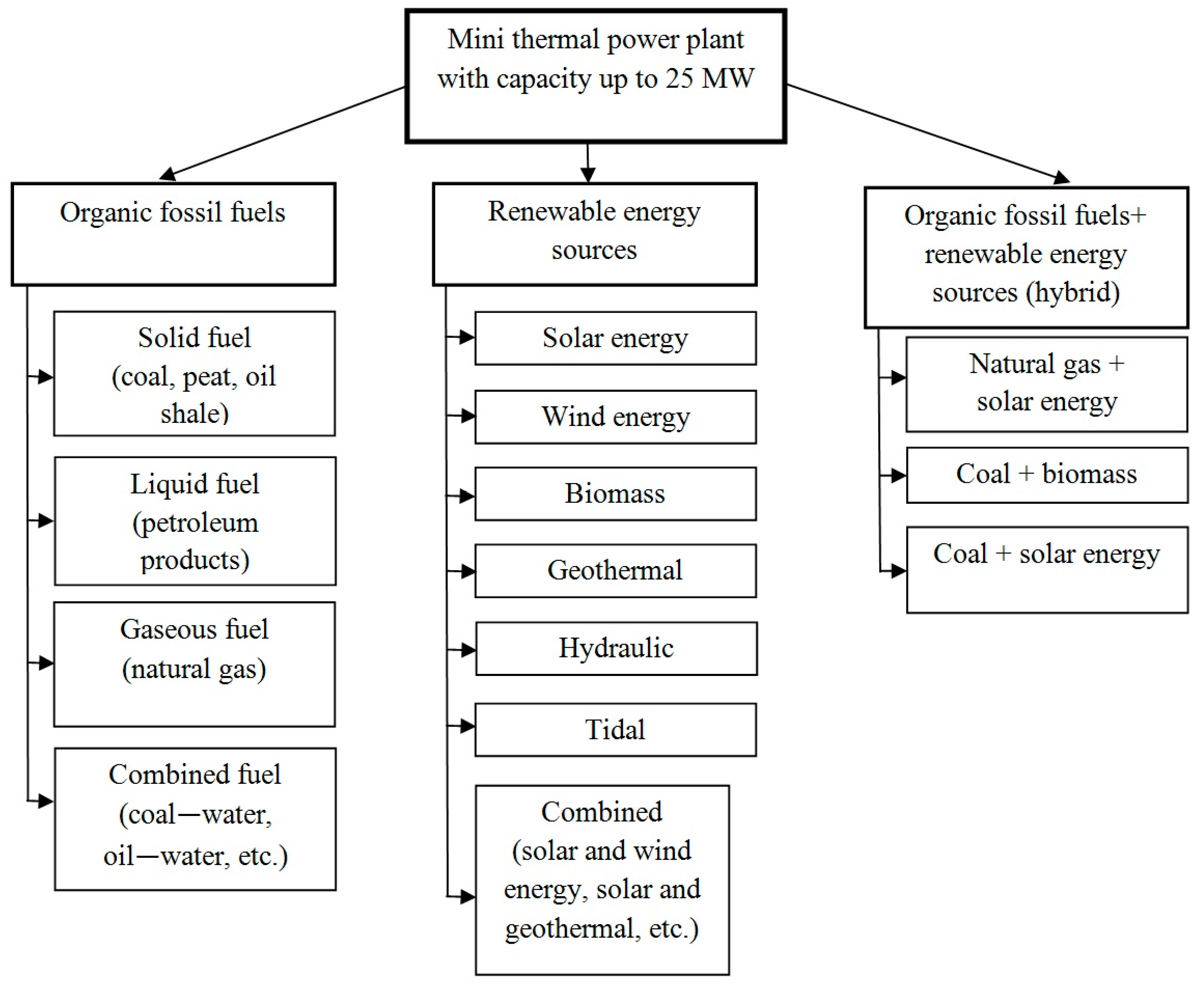
2.1. Mini Thermal Power Plant Classification

An important step for introducing small power plants into the general power system is the knowledge of the different types and characteristics. For this purpose, the paper preliminary reports a classification of modern mini thermal power plants, based on existing knowledge and perspectives of the latest scientific developments.
The most significant classification factor adopted is the type of primary energy resources. The classification is shown in Figure 1.
The existing plants can be divided into three groups—mini thermal power plants using only traditional fossil organic fuel, only RER and power plants operating with the basis of both traditional fuel and RER. Detailed description of mini thermal power plants operating with solid fuel is presented in the works of O. Afanaseva and G. Mingaleeva [16,17]. The solid fuel has a number of undoubted advantages over gaseous fuel in terms of ensuring the autonomous operation of the station and the location of the facility at a considerable distance from the main lines of fuel distribution.
When choosing a solid fuel, the structure of the fuel preparation unit is the most complex because drying and grinding are required. Coal, peat or oil shale can be burned in boiler furnaces in the form of dust and in a fluidized or dense layer, or gasified to produce a combustion gas. Fuel oil is burned in boilers as a liquid fuel, and as a diesel fuel if piston engines are used.
Traditional gaseous fuel is the natural gas; in the future, waste gases from petrochemical and coke-chemical enterprises can also be used, but there are several difficulties with the combustion, since the composition of such gases is variable and varies depending on the parameters of the main technological process.
In the technological schemes of this type, fuel cells can be used that significantly increase the efficiency of using gaseous fuel [18]. The interest for small-scale distributed power generation are combined types of fuels such as water–coal, oil–coal, water–peat, water–oil–coal and others. In relation to the technological qualities of the components and their integration into the process, industrial waste and low-quality fuels can also be used, providing that their properties are stabilized and have specified values [19].
Power plants operating only on RER are widely described in modern literature. There are several articles describing the operation of low-power plants [20]. Modern hybrid mini thermal power plants can combine the using of coal or natural gas and solar energy, coal and biomass [3].
Mini thermal power plants can also be classified according to other criteria that have a less pronounced effect on the structure of the technological scheme and the choice of main and service equipment:
  • By the number of resources. The number of energy resources is one of the factors that determine the complexity of HSRES, and its sustainability and efficiency; a large number of resources makes the system more complex, but at the same time, leads to increasing sustainability and energy efficiency;
  • By the type of energy produced: Mechanical energy—each turbine, independently of its type generates mechanical energy, which can be used directly, for example for pumping water or to be subsequently converted into electrical energy. Electrical energy can be easily distributed and converted to another type. Electricity can also be stored and consumed when it is needed. Thermal energy is used for heating and for many industrial, civil and technological processes. Thermal energy can be provided by combustion or recuperated as waste heat from thermal power plants or directly collected by means of solar thermal collectors and systems that use geothermal energy. Chemical energy, for example, the fuel production such as the hydrogen production by electrolysis. Mixed type—a typical example is a power system with a solar thermal collector combined with a wind turbine and photovoltaic cells.
  • By the availability of energy storage devices: with and without storage devices;
  • According to the presence of a connection to the distribution network: mini thermal power plants with a connection to the centralized power system must be synchronized with the distribution system. Autonomous mini thermal power plants are used to supply power to utilizers remote from the centralized power system.
Thus, in accordance with the proposed classification, approximately 20 different types of scheme of mini thermal power plants can be distinguished. The choice of the most effective scheme is determined by the type of fuel available for use or RER that are available in a given region, which have significant potential and a fairly low cost. Furthermore, the calculation of this scheme is carried out for material and energy flows, the selection of equipment and optimization of energy and economic indicators.

2.2. Characteristics of Climatic and Economic Conditions of the Republic of Vietnam

Vietnam is a developing country located in Southeast Asia and provided mainly with coal, oil, hydropower and RER [4]. The country is home to a large number of rural residents, so decentralized renewable energy technologies can play a role in the provision of electricity [5]. To promote RER, the Vietnamese government approved a Renewable Energy Master Plan for the period up to 2015 with a perspective until 2025 [6]. Among other activities, the plan prioritizes energy development in rural and remote areas. As a part of this activity, the Spanish International Development Cooperation Agency, together with the Vietnamese Ministry of Industry and Trade, facilitated the country’s solar radiation assessment and feasibility studies, including solar radiation and solar potential mapping [7].
The using and development of new additional energy resources for electricity generation in a country requires the provision of specific tools to all stakeholders to facilitate appropriate decision-making, project design and development activities. In the case of solar energy systems, a detailed knowledge of solar resources and their spatial distribution across the territory is critical for their getting into the country’s energy mix.
Vietnam is located in Southeast Asia, stretching between 9 and 23 degrees north. East Vietnam has a long coastline in Tongking Bay and the South China Sea. The Vietnamese climate is dominated by tropical monsoons with hot weather and high humidity. From May to September, southerly and southeasterly winds prevail in the Vietnamese climate. Between October and April, northern monsoons prevail with winds from north to northeast. There is a transition period of variable winds between each monsoon season twice a year.
Vietnam has a single rainy season between May and September (southern monsoon). During the rest time of the year the rains are infrequent and light. Annual precipitation is over 1000 mm almost throughout the country, and in the hills rises to 2000–2500 mm, especially in the region facing the sea.
The country is mountainous in the northwest and in the central highlands facing the South China Sea, which rises up to 2450 m. In the north around Hanoi and in the south around the city of Ho Chi Minh, there are vast low-lying areas in the Red River Delta and the Mekong Delta, respectively.
According to the updated version of the Kzpen-Geiger climate classification, Vietnam has three climatic zones [21]: equatorial monsoon (Am), equatorial savanna with dry winters (Aw) and subtropical with dry winters (Cwa).

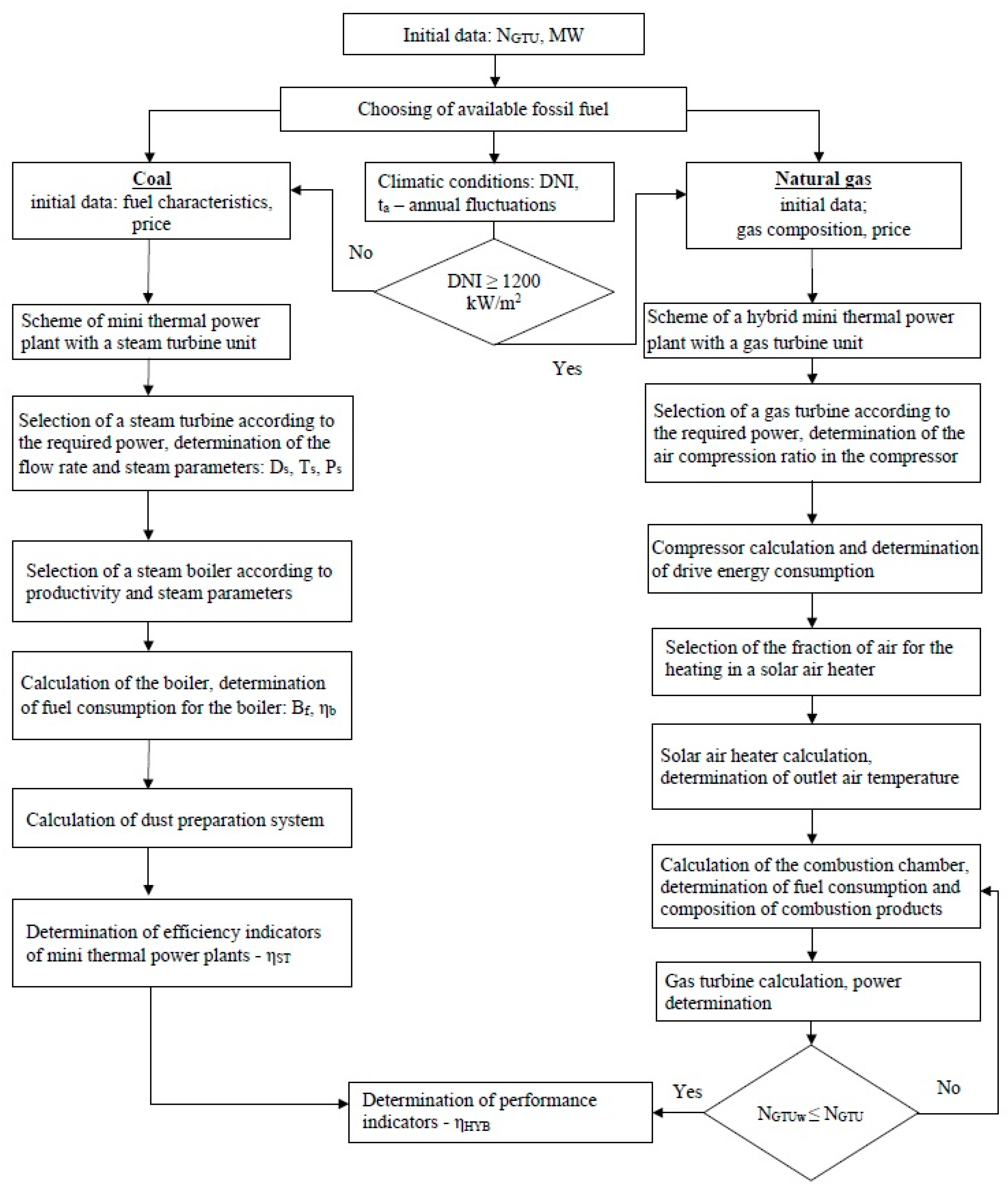
2.3. Used Algorithm for the Technological Scheme Selection of Mini Thermal Power Plant

Based on the analysis of the known and perspective technological schemes of mini thermal power plants and the methods used for their calculation, a generalized method for choosing the type of technological scheme and its calculation have been formed. The algorithm is shown in Figure 2.
The type of technological scheme is primarily determined by the type of fuel that is available in a given region or country, and the use of which is the most expedient. For the Republic of Vietnam, mainly coal can be used as fuel, the deposits of which are located in the northern part of the country, and natural gas, which is produced in the shelf zone or purchased in the liquefied form and supplied to the coast. However, due to the hot climate, the technological schemes based on gas turbines have a low efficiency, therefore, they can be used properly as a hybrid one, in connection with solar energy. Such schemes are advisable to use when the intensity of direct solar radiation is more than 1200 kW/m2. After the fuel and the type of technological scheme have been determined, the selection of the main equipment and its calculation can be carried out according to the existing methods.
On the basis of the calculated data on energy and material flows entering and leaving from each element of installation, the exergy, exergy efficiency of individual units and the entire technological scheme were determined.
The exergy method is the most general way of thermodynamic study of various energy conversion processes. It allows to determine the degree of excellence and sources of loss in installations and to find ways to improve them.
This method is widely presented in works related to the study of systems operating with the principle of combined generation of heat and electrical energy [22,23], however, it is rarely used for small-scale power generation objects operating with solid fuel.
Different directions of optimization of the composition and operating parameters of small power plants, both within the framework of energy complexes and as autonomous objects, were considered in the work [24]. When optimizing the location and power of distributed generation units, as an optimization criterion the energy losses during its distribution can be considered. Various evolutionary algorithms were used to determination the optimization problem [25,26,27,28,29,30,31]. Optimization with using a complex criterion of thermoeconomic efficiency makes it possible to take into account both the energy indicators of the object and the economic (capital and operating costs) [32]. Based on the performed analysis of optimization methods that are currently used for small distributed energy facilities and systems with RER, the following conclusion can be made. The optimization using the criterion of thermoeconomic efficiency (thermoeconomic efficiency) corresponds the purpose of the research and allows one to select a complete set of technological scheme and its operating parameters, to correlate them with capital and operating costs and obtain the maximum value of this criterion. The chosen criterion makes it possible to take into account the cost of primary energy resources that are used for energy production, their quality characteristics, which is especially important for hybrid schemes of low-power energy facilities.

2.4. Methodology of Calculating Mini Thermal Power Plants for Integration into the Energy System of the Republic of Vietnam

Based on the analysis of scientific and technical literature, it has been determinated that for small energy units to be located in Vietnam, it is advisable to use coal, gas and solar energy due to their availability and significant potential for use in technological schemes of small distributed energy units. Let’s consider two main schemes that can be recommended for small-scale power generation in Vietnam.
This is a scheme of a steam-turbine mini thermal power plant operating with local coal, the deposits of which are located in the northern part of the country, and a hybrid mini thermal power plant with gas turbine and solar air heater. The calculation methods for these schemes and the calculation results for the climatic conditions of Vietnam are presented below.

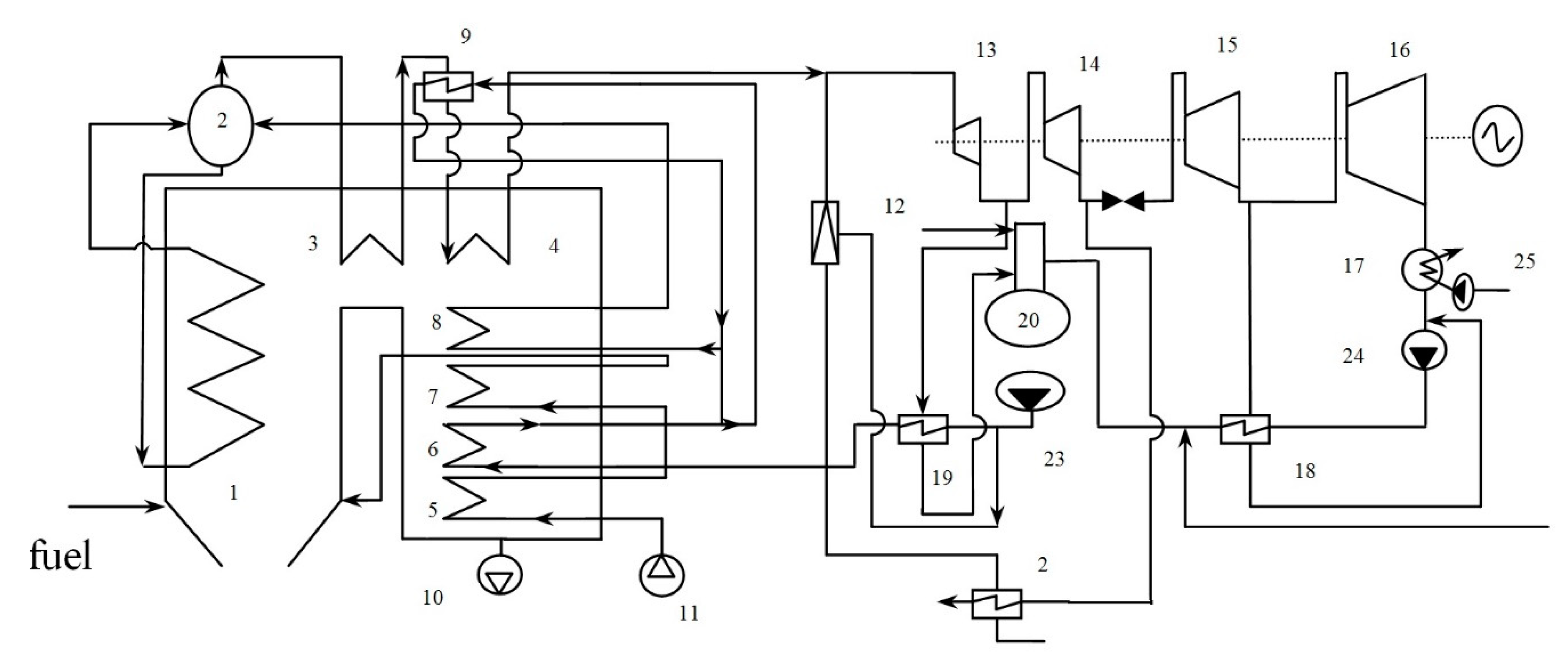
2.4.1. Exergy Efficiency Calculation Methodology Applied to a Steam-Turbine of a Mini Thermal Power Plant Operating with Coal

Considering already existing and operating mini thermal power plants, although they were designed and built for specific operating conditions, some typical schemes can be distinguished and classified according to the main equipment: steam boilers with steam turbines, gas turbine units with waste heat recovery boilers and diesel generators. Solid fuel (coal, peat and industrial carbon-containing waste) in these schemes can be burned in the furnaces of steam boilers or processed into gasifiers, which is then burned in the furnaces of gas boilers or in the combustion chambers of gas turbines. The equipment for thermal processing of solid fuels—gasifiers and pyrolysis reactors—is not yet commercially available. Therefore, for Vietnam, to start with traditional power schemes based on steam turbine units is advisable for the introduction of technologies for small-scale, distributed, autonomous generation units using coal or other types of solid organic fuel. The technological scheme of a steam-turbine mini thermal power plant is shown in Figure 3.
Pulverized fuel is fed to the burner of a steam boiler (1), which is equipped with a drum (2) and a two-stage superheater (3) and (4), which is designed to prepare steam with the required parameters for a steam turbine with four compartments (13, 14, 15 and 16). In the lower gas duct of the boiler, two stages of the economizer (6 and 8) and the air heater (5 and 7) were installed. In addition, to regulate the temperature of the steam, a surface desuperheater (9) is installed before the second stage, where feed water is supplied after the first stage of the economizer (6). Feed water and condensate are heated in the low pressure heater (18) and high pressure heater (19). Condensate, which returns to the boiler, passes through the deaerator (20). The delivery water is heated by steam from the turbine extraction in the network heater (21). In the peak mode the main steam from the pressure-reducing cooling unit (12) is used to heat the delivery water.
The air required for combustion is supplied by the forced-flow fan (11), and combustion products are removed using an induced-draft fan (10). At peak loads, the peak heater (22) enters into operation. Water is supplied to the system by a feed pump (23), condensate is pumped by a condensate pump (24) and cooling water is circulated to condenser (17) with a circulation pump (25).
According to the flow rate and parameters of the steam, which has to be supplied to the turbine, a solid fuel steam boiler was selected. The quality characteristics of the coal used determine the type and composition of the pulverization system. The steam turbine was selected according to the required power and taking into account the steam parameters produced in the steam boiler.
The efficiency of a steam boiler η b was determined from the inverse balance [33]:
η b = 100 ( q 2 + q 3 + q 4 + q 5 + q 6 )
where q 2 is the heat losses of exhaust gases, %; q 3 is the heat losses due to incomplete combustion of fuel, %; q 4 is the heat losses of unburned carbon, %; q 5 is the heat losses to the environment through the external walls of the boiler, % and q 6 is the heat losses of slag formed during coal combustion, %.
The objective is determining the heat losses for the adopted type of steam boiler and combustion fuel.
The fuel consumption B supplied to the combustion chamber of a steam boiler can be determined from the balance between the useful heat released by fuel combustion and the heat absorption of the fluid in the steam boiler, kg/s:
B Q A W η b = D S B ( h S S h F W ) + D R S ( h R S h R S ) + D B W ( h D W h F W )
where DSB is the estimated steam capacity of the boiler, kg/s; Q A W is the available heat at the boiler inlet, which is mainly determined by the heat of the combusted fuel, kJ/kg; h S S , h F W , h B W is the enthalpy of superheated steam, feed water and boiling water in the drum of a steam boiler, respectively, kJ/kg; D R S is the consumption of reheated steam, kg/s; h R S , h R S is the enthalpy of reheated steam at the inlet and outlet of the superheater, kJ/kg and D B W is the flow rate of blowdown water from a drum steam boiler, kg/s:
D B W = 0.01 p D S B
where p is the continuous boiler blowdown, %; at p < 2% the heat of the blowdown water is less than 0.4% of the useful heat release and may not be taken into account.
The consumption of burned fuel is named the estimated fuel consumption B E , its amount will be less than the total fuel consumption for the boiler according to Equation (2), if there is a mechanical underburning q 4 :
B E = B ( 1 0.01 q 4 )
To determine the consumption of dried fuel in the case of using an open-type dust preparation system with the discharge of the purified drying agent into the chimney, the first step is to find the calorific heat of the dried fuel Q L D for which the moisture content of the original and dried fuel must be known. The consumption of dried fuel B D supplied for combustion can be calculated as:
B D = B Q L W / Q L D
If the fuel consumption B is determined by the composition of the initial wet fuel with heating value Q L W , the dried fuel consumption can be determined directly with Equation (2), if Q L W is substituted by Q L D .
For drying and pulverizing coal, the most compact closed individual system with direct injection of coal dust into the boiler furnace and air drying, operating under pressure, was selected from typical schemes. For this system, the consumption of the drying agent, air, was determined. In such systems, three types of coal grinding mills can be used: ball pulverizer mill (BPM), hammer mill (HM) and bowl mill (BM). For mini thermal power plants with the existing standard size range, only ball pulverizer mill and hammer mill are suitable.
The heat balance of this type of system is written as follows (all components are indicated in kJ per 1 kg of crude fuel):
q 1 d a + q m e c h q e v a p q 2 d a q f q 5 = 0
where q 1 d a and q 2 d a is the heat of the drying agent at the entrance to the mill and at the exit from it, respectively; q m e c h is the heat released as a result of the work of the grinding bodies of the mill; q e v a p is the heat which spent on evaporation of fuel moisture; q f is the physical heat of fuel and q 5 is the heat loss to the environment.
The chemical exergy of coal can be defined in various ways [34]. In this paper the chemical exergy of coal was determined by the ratio proposed by V. Stepanov [35]:
e c h = [ 1.009 + 0.131 O + 0.116 W 100 ( A + W ) ] Q L W
where O is the oxygen content of the coal in terms of working mass, %, W is the moisture content in terms of working mass, % and A is the ash content of coal in terms of working mass, %.
The main process in pulverizing systems is drying, combined with grinding in coal grinding mills. All components of the exergy balance of the drying and grinding process can be determined by the known dependencies (J/s or W) [34], the exergy efficiency with the equation:
η d m = E c + E v a p + E d a E d a + i = 1 n L i + E c + E m e c h
where L i is the electrical power expended on equipment for drying and grinding; n is the number of devices with an electric drive; E v a p is the exergy of spent on evaporation of moisture from coal; E d a and E d a is the exergy of the drying agent at the entrance and exit from the mill, respectively; E c and E c is the exergy of coal entering the mill, and crushed coal, respectively and E m e c h is the exergy of the heat released during the grinding of coal.
The exergy efficiency of a steam boiler was calculated by the ratio:
η e x b = E s E f + E f w
where E f w is the exergy of feed water entering the boiler; E s is the exergy of steam generated in the boiler and E f is the exergy of the fuel entering the boiler.
The exergy efficiency of a steam turbine η e x S T is determined as follows:
η e x S T = N e + E S H E S S T + i = 1 m L i
where N e is the electric power generated by the steam turbine electric generator; E S H is the exergy of steam utilized for heating; E S S T is the exergy of steam supplied to the steam turbine from the boiler; L i is the electric power consumed with service equipment and m is the number of units of the service equipment of the steam turbine with an electric drive.
For a more complete assessment of the efficiency of a mini thermal power plant operating with solid fuel and producing thermal and electrical energy, the exergy efficiency of a steam-turbine mini thermal power plant was used, which does not include the internal flows of a steam turbine unit:
η T T P = N e + E S H E f + i = 1 k L i + E a + E f w + E m e c h
where k is the total number of units of service equipment for mini thermal power plants with an electric drive and E a is the exergy of air. The rest of the notations in Equation (11) are the same as in Equations (6)–(10).

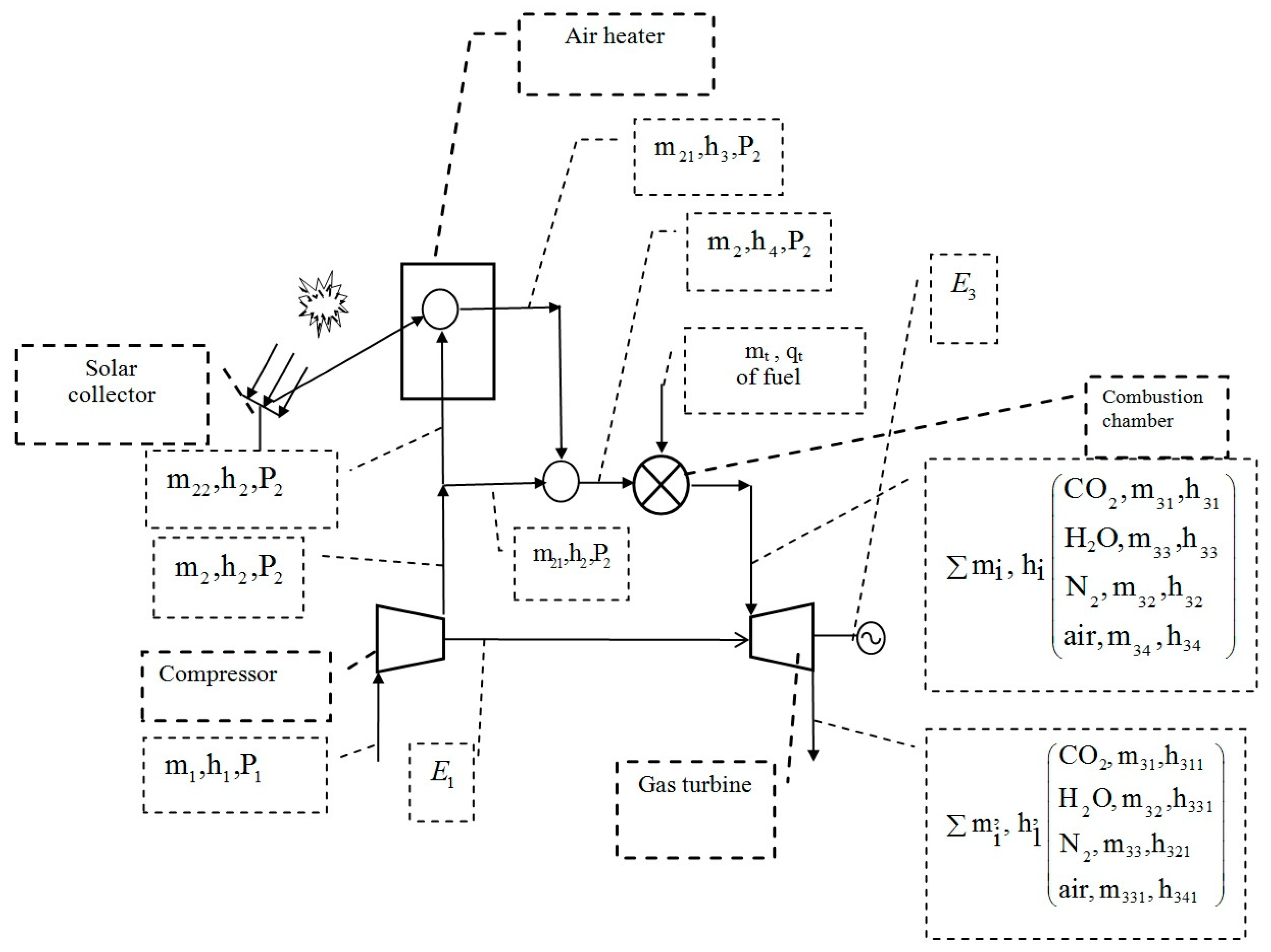
2.4.2. The Methodology for Calculating a Hybrid Mini Thermal Power Plant for Integration into the Power System of the Republic of Vietnam

In this article the schematic diagram of a hybrid mini thermal power plant operating on the basis of a gas–turbine plant was considered. For this case, the air coming from the compressor was heated in a solar air heater and natural gas was burned in the combustion chamber in order to further increase the enthalpy of the gas. After passing through the compressor, the air partially entered the air heater located on the solar tower. Here it received heat from solar radiation and then the heated air was mixed with the remaining air. The gas mixture was fed into the combustion chamber to burn the fuel and to obtain gases of a given temperature. The combustion products were sent to a gas turbine to generate electricity.
The scheme of the hybrid mini thermal power plant and the notations of the mass flow rates of the working media, enthalpy and pressure, respectively (m, h, p) is shown in Figure 4. To calculate the operating parameters of the energy production process in this application, a mathematical model was developed that includes the algebraic equations of mass flow rate and energy balance for each stage of energy conversion.
The air compression process in the compressor was characterized by the consumption of part of the power generated by the gas turbine, E 1 , kW:
m 1 h 1 + E 1 = m 2 h 2
where m 1 and m 2 is the mass air flow rate at the compressor inlet and outlet, respectively, kg/s and h 1 and h 2 is the enthalpy of air at the compressor inlet and at the outlet, respectively, kJ/kg.
The part of the air compressed in the compressor was directed to a solar air heater, which was located on the tower. Solar air heater was a heat exchanger with a porous insert (absorber), the inner surface of which was heated by concentrated solar radiation from heliostats located in the immediate vicinity of the station. The energy balance of this device is described with the equation:
m 21 h 2 + Q 2 = m 21 h 3
where m 21 is the mass flow rate of air at the entrance to the solar air heater and at the exit from it, kg/s; h 3 is the enthalpy of air at the exit from it, kJ/kg and Q 2 is the power of solar radiation spent on heating air m 21 , kW.
The following dependencies were used to determine Q 2 . The total thermal power of the solar receiver Q o v e r a l l was determined as the sum of the useful heat power Q 2 and losses Q l o s :
Q o v e r a l l = Q 2 + Q l o s
The total heat output of the solar receiver was determined depending on the parameters of the solar concentrator. After concentration the radiation intensity was increased to I r . The optical and geometric concentration ratios were related to the optical efficiency η o p t of the concentrator system and the radiation beam I b :
Q o v e r a l l = A r α r I r = A r α r η o p t C R g I b
In Equation (15), the concentration factor C R g can be defined as:
C R g = A a A r
where A a is the collector aperture area; A r is the area of the receiving surface; α r is the absorption capacity of the surface; η o p t is the optical efficiency and I b is the intensity of solar radiation.
Losses were determined by the temperature of the receiver T r and the emissivity of the receiver surface ε r , while the overall convection coefficient U l o s was used to account for convection losses at environmental temperature T a :
Q l o s = A r ε r ( T r 4 T a 4 ) + U l o s ( T r T a )
The thermal efficiency η r of the receiver and collector can be calculated using the expression:
η r = Q 2 A a I a = η o p t α ε r σ ( T r 4 T a 4 ) U l o s ( T r T a ) C R g I b
The air heated by solar radiation and the air coming directly from the compressor were mixed before being fed into the combustion chamber. The enthalpy of the mixture was determined based on the following balance:
m 2 h 4 = m 21 h 3 + m 22 h 2
where m 22 is the mass flow rate of the remaining air leaving the compressor, kg/s; h 4 is the enthalpy of the air mixture, kJ/kg and m 2 is the mass flow rate of the air mixture, kg/s. Values m 21 and m 22 are related with the ratio:
m 21 = ϕ m 2 ; m 22 = ( 1 ϕ ) m 2
where ϕ is the fraction of air directed to the air heater.
The energy balance of the combustion chamber is expressed by the equation:
m 2 h 4 + m F Q L W = m 31 h 31 + m 32 h 32 + m 33 h 33 + m 34 h 34 = m i h i
where m F is the mass fuel rate consumption, kg/s; h 31 is the enthalpy of CO2 leaving the combustion chamber, kJ/kg; h 32 is the enthalpy of N2 leaving the combustion chamber, kJ/kg; h 33 is the enthalpy of H2O leaving the combustion chamber, kJ/kg; h 34 is the enthalpy of excess air leaving the combustion chamber, kJ/kg and m 31 , m 32 and m 33 are the mass flow rates of fuel combustion products—CO2, H2O and N2, respectively.
The gas turbine operation is characterized by the following balance:
m 31 h 31 + m 32 h 32 + m 33 h 33 + m 34 h 34 = = E 1 + E 3 + m 31 h 311 + m 32 h 321 + m 33 h 331 + m 341 h 341
where m 341 is the mass air flow after the turbine, kg/s; h 311 is the enthalpy of CO2 at the outlet from the turbine, kJ/kg; h 321 is the enthalpy of N2 at the outlet of the turbine, kJ/kg; h 331 is the enthalpy of H2O at the turbine outlet, kJ/kg; h 341 is the enthalpy of air at the outlet of the turbine, kJ/kg and E 3 is the useful power produced with the turbine, kJ/s.

2.4.3. Thermoeconomic Efficiency Calculation

To simulate the integration of small distributed generation power plants into the energy system of the Republic of Vietnam, an analysis of the level of economic development of provinces was carried out. The selection criterion was a population of more than 1 million people (except for the "sunniest" province of Ninh Thuan) and a GDP per capita of more than 2.5 thousand dollars. The availability of coal, natural gas and solar energy was considered. Thus, 7 provinces were selected for the placement of small-scale energy objects, the data for which are presented in Table 1.
Variants of construction of steam-turbine coal-fired and hybrid gas-turbine mini thermal power plant using solar energy with the ratio of their capacities α = 0.2; 0.3; 0.5 and 0.7 were considered.
As a criterion for choosing the best option for integrating mini thermal power plants into the energy system of the Republic of Vietnam, the coefficient of thermoeconomic efficiency was chosen, which combines energy and economic indicators [16,37]:
ϕ = η e x / ( 1 + i = 1 n ( K + C ) i ( B f C f ) i ) max
where η e x is the exergy efficiency of the scheme; K is the specific capital cost, $/year; C is the operating cost; B f is the annual consumption of coal, t/year and C f is the cost of coal, $/t.
The overall exergy efficiency for the considered option was calculated according to the dependence:
η e x o v e r a l l = 1 m N G i + 1 n N S T P j i m ( E f i + L i + E a i ) + 1 n ( E c . a j + L j + E c o a l j + E m e c h j )
where N G i is the capacity of the hybrid power plant; N S T P i is the capacity of steam-turbine power plant; E f i is the exergy of natural gas supplied to the i-th hybrid station; L i is the energy consumption of drive of hybrid station equipment; E a i is the exergy of the air supplied to the hybrid station; E c . a j is the exergy of the drying agent supplied to the steam-turbine station; L j is the energy consumption for the drive of steam-turbine station equipment; E c o a l j is the exergy of coal supplied to the steam-turbine station and E m e c h j is the exergy of heat which released during the operation of grinding bodies of a coal mill.

3. Results

By using the developed model, mini thermal power plants with a capacity of 4.6 and 11.86 MW were calculated, for which operating data that can allow checking the adequacy of the model were available. As an example of the calculation, the change in flow characteristics was presented with a variation of the intensity of direct solar radiation and with a change in air temperature for Ninh Thuan province of the Republic of Vietnam
The obtained data show that when DNI changed from 0 to 745.98 kW/m2, the fuel consumption for mini thermal power plants with a capacity of 4.6 MW decreased by 57.2%, and for mini thermal power plants with a capacity of 11.86 MW by 55.5%. Calculations made for an annual cycle of operation show a decrease in fuel consumption for the climatic conditions of this province by 7.1 and 5.3%, respectively.
Based on the theoretical studies of the technological schemes of mini thermal power plants, a model for integrating small distributed generation components of various types of energy resources into the energy system of the Republic of Vietnam was developed, taking into account the requirements of energy security and the prospects for the development of RER. With the using of this model, an appropriate energy development plan can be drawn up, the type of power plant, fuel and the region for the location of mini thermal power plants can be selected.
According to the estimates presented in the energy development scenario of Vietnam by 2030, Vietnam would lack about 50 TW·h by 2030, which is equivalent to 5700 MW of installed capacity. According to the world average, small power plants account for about 10%, so Vietnam needs to build small thermal power plants with a total capacity of N = 570 MW.
Currently there are solar power plants in the Republic of Vietnam, which are located mainly in the Ninh Thuan province, where the intensity of solar radiation has the highest values. All solar power plants built in Ninh Thuan province had a fairly large capacity more than 30 MW. Connecting them to a centralized network leads to problems due to its congestion. The possibilities of small distributed generation, which are facilities with a capacity of up to 25 MW, are practically not used. An important feature of such facilities is that they can operate autonomously and will not create additional load on distribution networks.
Calculations were carried out for 16 options for placing mini thermal power plants in the provinces of the Republic of Vietnam with the share of hybrid mini thermal power plants changed from 20 to 80% of mini thermal power plants capacity. For coal-fired steam-turbine mini thermal power plants, options were calculated for all types of coal used.
The results of choosing the best option, based on the value of the general indicator of thermoeconomic efficiency of the distribution of mini thermal power plants by type and capacity, are presented in Table 2.

4. Discussion

The obtained results show that the coal-fired steam-turbine power plant should be located closer to coal deposits in Hai Phong and Quang Ninh provinces. It is advisable to build only mini thermal power plants with a capacity of 25 MW, because they had the highest exergy efficiency in comparison with plants of lower power. Their exergy efficiency was 34%. These provinces are located in the north of Vietnam and had a low intensity of solar radiation, due to which the exergy efficiency of hybrid stations in these provinces was significantly lower than in southern regions and was about 31%. Therefore, it is not recommended to place hybrid stations in these provinces. The thermoeconomic efficiency for coal-fired steam power plant was significantly lower than for the hybrid ones. However, it should be considered that coal for the northern provinces is a local fuel and its delivery to the station is inexpensive and reliable.
Hybrid plants were more effective, especially with a capacity of 4.6 MW. The placement of hybrid mini thermal power plants is recommended in the provinces of Binh Duong, Da Nang, Heng Hoa, Ninh Thuan and Ho Chi Minh, located in the southern and southeast part of Vietnam. In addition, these provinces are provided with the supply of liquefied natural gas. The exergy efficiency of hybrid stations could reach 37.3%, and the thermoeconomic efficiency was 7.07%. For the optimal placing option of mini thermal power plants this indicator for the whole segment of small-scale distributed energy was 6.77%. For other options of mini thermal power plants placing the overall thermoeconomic efficiency ranged from 5.53 to 6.74%.
In this way the placing of mini thermal power plants of two types coal-fired-steam-turbine power plant and hybrid based on gas turbine units and solar air heaters in 7 provinces of the Republic of Vietnam will ensure the development of the small-scale distributed energy sector and reliable supply of the population of these provinces with electric energy. Integration of autonomous mini thermal power plants into the country’s energy system will reduce the load on the electrical grid and contribute to the intensive development of these provinces.

5. Conclusions

The prospects for the introduction of small distributed generation power plants operating with the basis of complementary using of traditional and RER into the energy system of the Republic of Vietnam were performed. The classification of mini thermal power plants by the type of primary energy resources and by other classification features was proposed. It was revealed that for small energy facilities that can be located in Vietnam, it is advisable to use coal, gas and solar energy due to their availability and significant potential for use in technological schemes of hybrid mini power plants.
The technological schemes of mini thermal power plants, which can be used in the small-scale energy sector of the Republic of Vietnam, were considered—with the steam turbines operating with coal, and gas turbine units. The calculation of these schemes for the power range, steam turbine from 6 to 25 MW and gas turbine from 1.2 to 15.5 MW, was carried out. The calculation results showed that the efficiency of thermal power plants of low power up to 25 MW was on average lower than for more powerful plants. Therefore, it is necessary to implement energy and resource saving measures, for example, to improve the scheme for a gas turbine unit, by using solar energy for the heating of air entering the combustion chamber.
A mathematical model of the technological scheme of hybrid mini thermal power plant using a gas turbine unit and heating a part of the air from the compressor into a solar heater located on a tower and operating with the basis of the technology of solar radiation concentration was developed. The operating parameters and efficiency indicators of mini thermal power plants with a capacity of 4, 6 and 11.86 MW with a change of direct normal radiation intensity (DNI) and ambient temperature conditions were considered. The obtained data show that when DNI changed from 0 to 745.98 kW/m2, fuel consumption for mini thermal power plants with a capacity of 4.6 MW decreased by 57.2% and for mini thermal power plants with a capacity of 11.86 MW, by 55.5%. Calculations made for an annual cycle of operation show a decrease in fuel consumption for the climatic conditions of this province by 7.1 and 5.3%, respectively.
A model for the integration of small distributed generation components into the energy system of the Republic of Vietnam was developed. The thermoeconomic efficiency was the selection criterion, the value of which for the best option for the placement of mini thermal power plants, taking into account the values of the initial investment in construction for 2020, amounted to 7.07%. The presented scientific and methodological developments will generate energy and resource saving with effects on the scale of the given state.

Author Contributions

Conceptualization G.M., O.A., D.T.N., D.N.P., P.Z.; methodology G.M. and O.A; software O.A.; validation D.N.P.; formal analysis D.T.N., D.N.P. and O.A.; investigation D.N.P.; resources P.Z.; data curation P.Z.; writing—original draft preparation G.M.; writing—review and editing G.M.; visualization G.M.; supervision D.N.P.; project administration O.A.; funding acquisition O.A.; All authors have read and agreed to the published version of the manuscript.

Funding

Funding for open access charge: Russian Academic Excellence Project 5-100.

Conflicts of Interest

The authors declare no conflict of interest.

References

  1. World Seals Landmark Climate Accord, Marking Turn from Fossil Fuels. Reuters. Thomson Reuters (12 December 2015). Available online: http://www.reuters.com/article/us-climatechange-summit-idUSKBN0TV04L20151212#gVKudBATCD0EGdxL.97 (accessed on 24 September 2020).
  2. Suntio, T.; Messo, T. Power Electron. Renew. Energy Sources. Energies 2019, 12, 1852. [Google Scholar] [CrossRef] [Green Version]
  3. Opportunities for Research and Development of Hybrid Power Plants. Technical Report NREL/TP-5000-75026 May 2020. Available online: https://www.nrel.gov/docs/fy20osti/75026.pdf (accessed on 24 September 2020).
  4. Minh, D.T.; Sharma, D. Vietnam’s energy sector: A review of current energy policies and strategies. Energy Police 2011, 39, 5770–5777. [Google Scholar] [CrossRef]
  5. Nguyen, K.Q. Alternatives to grid extension for rural electrification: Decentralized renewable energy technologies in Vietnam. Energy Police 2007, 35, 2579–2589. [Google Scholar] [CrossRef]
  6. Khanh, T.P.; Minh, B.N.; Ha, D.N. Energy supply, demand, and policy in Vietnam, with future projections. Energy Police 2011, 39, 6814–6826. [Google Scholar] [CrossRef]
  7. Thenepalli, T.; Ngoc, N.T.M.; Tuan, L.Q.; Son, T.H.; Hieu, H.H.; Thuy, D.T.N.; Thao, N.T.T.; Tam, D.T.T.; Huyen, D.T.N.; Van, T.T.; et al. Technological Solutions for Recycling Ash Slag from the Cao Ngan Coal Power Plant in Vietnam. Energies 2018, 11, 2018. [Google Scholar] [CrossRef] [Green Version]
  8. Polo, J.; Bernardos, A.; Navarro, A.A. Fernandez-Peruchena, C.M. Solar resources and power potential mapping in Vietnam using satellite-derived and GIS-based information. Energy Convers. Manag. 2015, 98, 98348–98358. [Google Scholar] [CrossRef]
  9. Seshie, Y.M.; N’Tsoukpoe, K.E.; Neveu, P.; Coulibaly, Y.; Azoumah, Y.K. Small scale concentrating solar plants for rural electrification. Renew. Sustain. Energy Rev. 2018, 90, 195–209. [Google Scholar] [CrossRef]
  10. Gambini, M.; Vellini, M.; Stilo, T.; Manno, M.; Bellocchi, S. High-Efficiency Cogeneration Systems: The Case of the Paper Industry in Italy. Energies 2019, 12, 335. [Google Scholar] [CrossRef] [Green Version]
  11. Calise, F.; d’Accadia, M.D.; Piacentino, A.; Vicidomini, M. Thermoeconomic Optimization of a Renewable Polygeneration System Serving a Small Isolated Community. Energies 2015, 8, 995–1024. [Google Scholar] [CrossRef] [Green Version]
  12. Yu, Y.; Chen, H.; Chen, L. Comparative Study of Electric Energy Storages and Thermal Energy Auxiliaries for Improving Wind Power Integration in the Cogeneration System. Energies 2018, 11, 263. [Google Scholar] [CrossRef] [Green Version]
  13. Abagnale, C.; Cameretti, M.C.; De Robbio, R.; Tuccillo, R. Thermal Cycle and Combustion Analysis of a Solar-Assisted Micro Gas Turbine. Energies 2017, 10, 773. [Google Scholar] [CrossRef] [Green Version]
  14. Huang, S.; Li, C.; Tan, T.; Fu, P.; Wang, L.; Yang, Y. Comparative Evaluation of Integrated Waste Heat Utilization Systems for Coal-Fired Power Plants Based on In-Depth Boiler-Turbine Integration and Organic Rankine Cycle. Entropy 2018, 20, 89. [Google Scholar] [CrossRef] [Green Version]
  15. Stoltmann, A. Hybrid Multi-Criteria Method of Analyzing the Location of Distributed Renewable Energy Sources. Energies 2020, 13, 4109. [Google Scholar] [CrossRef]
  16. Afanasyeva, O.V.; Mingaleeva, G.R. Thermo-economic efficiency of low capacity coal-based power plants. Int. J. Exergy 2011, 8, 175–193. [Google Scholar] [CrossRef]
  17. Afanasyeva, O.V.; Mingaleeva, G.R. Comprehensive exergy analysis of the efficiency of a low-capacity power plant with coal gasification and obtaining sulfur. Energy Effic. 2015, 8, 255–265. [Google Scholar] [CrossRef]
  18. Pirkandi, J.; Jahromi, M.; Sajadi, S.Z.; Ommian, M. Thermodynamic performance analysis of three solid oxide fuel cell and gas microturbine hybrid systems for application in auxiliary power units. Clean Technol. Environ. Policy 2018, 20, 1047–1060. [Google Scholar] [CrossRef]
  19. Mantripragada, H.C.; Rubin, E.S. Techno-economic evaluation of coal-to-liquids (CTL) plants with carbon capture and sequestration. Energy Policy 2011, 39, 2808–2816. [Google Scholar] [CrossRef]
  20. Raj, N.T.; Iniyan, S.; Goic, R. A review of renewable energy based cogeneration technologies. Renew. Sustain. Energy Rev. 2011, 15, 3640–3648. [Google Scholar] [CrossRef]
  21. Peel, M.C.; Finlayson, B.L.; McMahon, T.A. Updated world map of the Köppen-Geiger climate classification. Hydrol. Earth Syst. Sci. Discuss. 2007, 4, 439–473. [Google Scholar] [CrossRef] [Green Version]
  22. Valero, A.; Serra, L. Fundamentals of exergy cost accounting and thermoeconomics. Trans. ASME. J. Energy Resour. Technol. Pt. 1 Theory Cent. Energy Resour. Consum. 2006, 1, 1–8. [Google Scholar]
  23. Ozgur, B. Exergoeconomic analysis of a combined heat and power (CHP) system. Int. J. Energy 2008, 32, 273–289. [Google Scholar]
  24. Essackjee, I.A.; Ah King, R.T.F. Impact of Introducing Small Scale Distributed Generation on Technical Losses in a Secondary Distribution Network. LNNE 2006, 416, 71–80. [Google Scholar]
  25. Hooshmand, R.; Ataei, M. Optimal capacitor placement inactual configuration and operational conditions of distribution system using RCGA. J. Electr. Eng. 2007, 58, 189–199. [Google Scholar]
  26. Dlfanti, M.; Granelli, G.P.; Maranninio, P. Optimal capacitor placement using deterministic and genetic algorithm. IEEE Trans. Power Syst. 2000, 15, 1041–1046. [Google Scholar] [CrossRef]
  27. Reddy, M.D.; Reddy, V.C. Optimal capacitor placement using fuzzy and real coded genetic algorithm for maximum savings. J. Theor. Appl. Inf. Technol. 2008, 4, 219–226. [Google Scholar]
  28. Huang, T.; Hsiao, Y.; Jiang, C.J. Optimal placement of capacitors in distribution systems using an immune multi–objective algorithm. Int. J. Electr. Power Energy Syst. 2008, 30, 184–192. [Google Scholar] [CrossRef]
  29. Hattacharya, S.K.; Goswami, S.K. A new fuzzy based solution of the capacitor placement problem in radial distribution system. Expert Syst. Appl. 2009, 36, 4207–4212. [Google Scholar] [CrossRef]
  30. Wang, L.; Yang, Z.; Sharma, S.; Mian, A.; Lin, T.-E.; Tsatsaronis, G.; Maréchal, F.; Yang, Y.A. Review of Evaluation, Optimization and Synthesis of Energy Systems: Methodology and Application to Thermal Power Plants. Energies 2019, 12, 73. [Google Scholar] [CrossRef] [Green Version]
  31. Yang, Y.; Li, X.; Yang, Z.; Wei, Q.; Wang, N.; Wang, L. The Application of Cyber Physical System for Thermal Power Plants: Data-Driven Modeling. Energies 2018, 11, 690. [Google Scholar] [CrossRef] [Green Version]
  32. Martynovsky, V. Analysis of Actual Thermodynamic Cycles; Energiya: Moscow, Russia, 1972; p. 206. [Google Scholar]
  33. Kuznetsov, N.; Mitor, V.; Dubovskiy, I.; Karasina, E. Thermal Calculation of Boiler Units. Standard Method; EKOLIT: Moscow, Russia, 2011; p. 296. [Google Scholar]
  34. Szargut, J.; Petela, R. Egzergia; Wydawnictwo naukowo-techniczne: Warszawa, Poland, 1965; p. 411. [Google Scholar]
  35. Stepanov, V. The Chemical Energy and Exergy of Substances, 2nd ed.; Nauka: Novosibirsk, Russia, 1990; p. 164. [Google Scholar]
  36. Nguen, D.T.; Pham, D.N.; Mingaleeva, G.R.; Afanaseva, O.V.; Zunino, P. Assessment of efficiency and prospects for the use of hybrid thermal low-capacity power plants in the Republic of Vietnam. E3S Web Conf. 2019, 124, 01040. [Google Scholar] [CrossRef] [Green Version]
  37. Yantovsky, E. Energy and Exergy Currents; Nauka: Moscow, Russia, 1988; p. 144. [Google Scholar]
Figure 1. The classification of mini thermal power plants by the type of primary energy resources.
Energies 13 05848 g001
Figure 2. The algorithm of the generalized method for choosing the type of technological scheme of mini thermal power plant and its calculation.
Energies 13 05848 g002
Figure 3. Technological scheme of a steam-turbine mini thermal power plant.
Energies 13 05848 g003
Figure 4. Schematic diagram of a hybrid mini thermal power plant with a solar air heater [36].
Energies 13 05848 g004
Table 1. The basic data on the provinces of the Republic of Vietnam selected for the placement of mini thermal power plants.
Province or City NameGDP per Capita (thousand USD/person/year)Population, PeopleSolar Radiation Intensity DNI, kW/m2
Coal-fired steam turbine mini thermal power plants
1Hai Fong4.2171,837,173700
2Quang Ninh5.111,320,324675
Hybrid gas turbine mini thermal power plants
3Binh Duong5.6812,426,5611285
4Da Nang3.6121,134,3101293
5Heng Hoa2.6981,231,1071620
6Ninh Thuan1.724590,4671764
7Ho Chi Minh6.7258,993,0821443
Table 2. Indicators of the best option for integrating mini thermal power plants into the energy system of the Republic of Vietnam.
Option: 20% Coal-Fired Steam Turbine (Coal Type 4b) and 80% Hybrid Gas Turbine Mini Thermal Power Plants
TypeName of Province/CityCapacity of Mini Thermal Power Plant, MWAmount of Mini Thermal Power PlantsFuel Consumption for one Mini Thermal Power Plant, kg/sInitial Investment, US $ MillionCost of Operation and Maintenance per year, US $ MillionFuel Costs per year, US $ millionExergy Efficiency, ηex, %Thermo-economic Efficiency, φ, %
Coal Steam TurbineHai Phong + Quang Ninh2542.851503.3329.7534.674.85
Hybrid Mini Thermal Power PlantsBinh Duong4.6140.241900.7161.1936.37.02
11.8620.68571.160.2624.9532.86.75
Da Nang4.650.239690.2621.7636.47.02
11.8600.67900033.00
Heng Hoa4.6140.2351930.7159.9237.07.07
11.8620.67171.160.2624.4433.56.81
Ninh Thuan4.6240.2333311.2310237.37.09
11.8680.6672851.0597.1833.76.82
Ho Chi Minh4.6140.2381930.7160.6836.67.04
11.8600.67800033.10
Total (average) values568.9 15608.5448235.576.77
Publisher’s Note: MDPI stays neutral with regard to jurisdictional claims in published maps and institutional affiliations.

