Abstract
Development of technologies, materials, support systems, and coatings has made the integration of solar thermal systems into the building envelope increasingly possible. Solar thermal collectors can either be directly integrated, substituting conventional roof or façade covering materials, or constitute independent devices added to a roof or façade structure. Aimed at estimating the real effectiveness of building-integrated solar systems for domestic heat water (DHW) production or for heating integration, when horizontal or inclined pitches on buildings are not applicable, the authors analyze a case study with different scenarios, taking into account the issues connected to a highly urbanized context in the Mediterranean climate. A GIS model was used for estimating the energy balance, while the real producibility of the simulated systems was calculated by a dynamic hourly simulation model, realized according to ISO 52016. The savings in terms of primary energy needs obtained by installing solar thermal systems on the facade are presented, and the differences between the cases in which the system is used for DHW production only and for space heating too are distinguished and discussed. The evaluated potential is quantified in the absence of roof collectors, despite their high potential in the Mediterranean region, in order to better appreciate the effects induced by integrated facade systems.
1. Introduction
In recent years, increasing attention to the integration of solar systems with aesthetic and technical elements of the envelope (e.g., roofs, façades, and frames) in modern buildings has been paid by designers and building owners. To this aim, technological innovation in photovoltaic (PV) and solar systems is today specifically oriented to the possibility to adapt shape, color, dimensions, superficial finishing, type of material, etc. [1,2], thus reaching the so-called “aesthetical compatibility.” From a technical and engineering point of view, the greatest possibilities of architectural integration offered by PV systems are undisputed. Just think of the stiffness of the pipes transporting hot water compared to cables transporting electricity, the dimensions of the individual modules (cells and absorbers), without forgetting, finally, the characteristics of the energy produced: thermal energy is intended for consumption in the immediate vicinity of the place where it is produced, while electricity can also be transported over great distances [3,4]. However, from the point of view of the potential of the envelope, vertical facades generally offer large and well-sunny surfaces, but on the other hand they represent the public image of the building for which energy issues are often sacrificed in favor of architectural coherence. Moreover, existing collectors were developed as purely technical elements, designed to optimize heat collection, production, and installation. Generally, a marginal attention to architectural integration issues was traditionally given at the design phase of PV and solar systems, leaving the responsibility of adapting materials, dimensions and shapes of these systems into the building to the architect.
Recently, a great variety of components for solar thermal systems (the solar panel, the waterproof frame, the isolation systems, the solar heater) have been patented, produced, and distributed to be “directly” installed in the buildings without considering the impact from an architectural point of view. As a matter of fact, the use of new technologies in solar plants is still subordinated to the achievement of energetic performance and their integration in a unitary architectonic building framework is still considered secondary. However, there are some exceptions; for example, in recent projects of architects Thomas Herzog and Georg W. Reinberg, careful attention to the “shapes” of solar systems and components rather than to the “merely technical” aspects is evident. Therefore, it can be concluded that, in a global technical and environmental approach, solar systems become one of the means for the “sensible and vital understanding of the new relation between the Man and the Atmosphere, the Today and Tomorrow, and between the men reciprocally” [5].
The installations of solar systems on the roofs quickly spread between the end of 1980s and the beginning of 1990s, especially in the northern and western EU countries. Important examples are the innovative energetic policies in Denmark and the UK, usually within public programs of city requalification or expansion, or the solar thermal systems realized within the communitarian programs Joule and Thermie (1990–1998). A meaningful contribution to their technical-economic development is also represented by the demonstrative participations in the program IEA Task 13 [6], where remarkable relevance to solar heating systems is given, or within the initiatives of Task 20 [7], finalized to solar installations in retrofit operations. Finally, within the IEA Task 23 [8] methods, procedures, tools, and standards have been elaborated that are aimed at optimizing integration at each planning stage, from the pre-design until to the design development. The first significant changes in conceiving the solar integration are recorded from the end of 1980s when renewable energies utilization became an effective tool for a sustainable approach in buildings construction. At the same time, the building envelope, thanks to recently technological innovation, has shown the potentiality of being a dynamic, interactive element, capable of regulating and optimizing the energy flows between the indoor and outdoor environments. By observing the development of morphological and technical solutions in solar thermal integration over the last few years, it is clear that solar thermal systems will be increasingly conceived as an essential part of the architectural framework of the buildings rather than just technical elements [9,10,11].
The architectural integration of solar systems is a crucial issue when architectural constraints are present in the building. This is the case of all real estate “that make up a characteristic appearance with an aesthetic and traditional value” [12], whose definition is extended to all historic urban centers. In Italy, most of the historical buildings fall within this definition and are therefore excluded from the application of the regulations in force on energy efficiency [13,14,15]. Furthermore, the obligation to install RES systems on new buildings or major renovations is not mandatory for buildings under cultural heritage and landscape protection [16], unless the designer “highlights that compliance with the requirements implies an alteration incompatible with their character or appearance, with particular reference to historical and artistic value [17]. This represents a huge responsibility for designers without providing any indication of the possible evaluation or judgment criteria of the “incompatible alteration” occurring, with the risk that any solution may be opposed. Therefore, it is evident that, at national level, the issues of energy efficiency and the protection of cultural heritage are still separate, making it necessary to integrate the respective implementing regulations, in consideration of the huge historical building heritage in Italy, whose contribution to national energy needs can be significant.
Objective
In this paper, the authors present an overview of some of the most successful building integration technologies of solar thermal systems available, highlighting the main issues faced in the design phase. The study is focused on the so-called “active technologies”—that is, those technologies capable to capture solar energy but completely independent from the elements of the envelope on which they must be installed. In the literature, there are several cases of architectural integration made with more or less significant energy and economic advantages, but always with respect to the situation of a complete absence of such systems. It is difficult to find information on how much architectural integration actually weighs on the energy and economic contribution compared to the use of solar systems without any architectural constraints. In order to estimate the real contribution of solar systems for domestic heat water (DHW) production or for heating integration, when horizontal or inclined pitches on condominium buildings are not usable, the authors analyze a case study with different scenarios. The GIS DB model developed by some of the authors and presented in [18] was used for estimating the energy balance in the highly urbanized contexts where the condominium is placed. The innovative aspect of this research is the realistic aspect of the simulation, not comparing different architectural integration choices, but evaluating, at least among some of the most popular ones on the market, their potential of energy production in a highly urbanized context. In particular, the effects of shading on the best exposed facades of the building, caused by similar buildings in the immediate vicinity, were analyzed. The case study is located in a highly urbanized context of Cagliari (IT), which is characterized by a typical warm Mediterranean climate. The results presented in this paper constitute only a first step of the research and an in-depth study in the near future, with a greater number of influencing factors (e.g., latitude, available surfaces, age of the building, environmental constraints, etc.), will be carried out, in order to verify to what extent architectural integration could be considered convenient.
2. Technologies for Collectors’ Integration
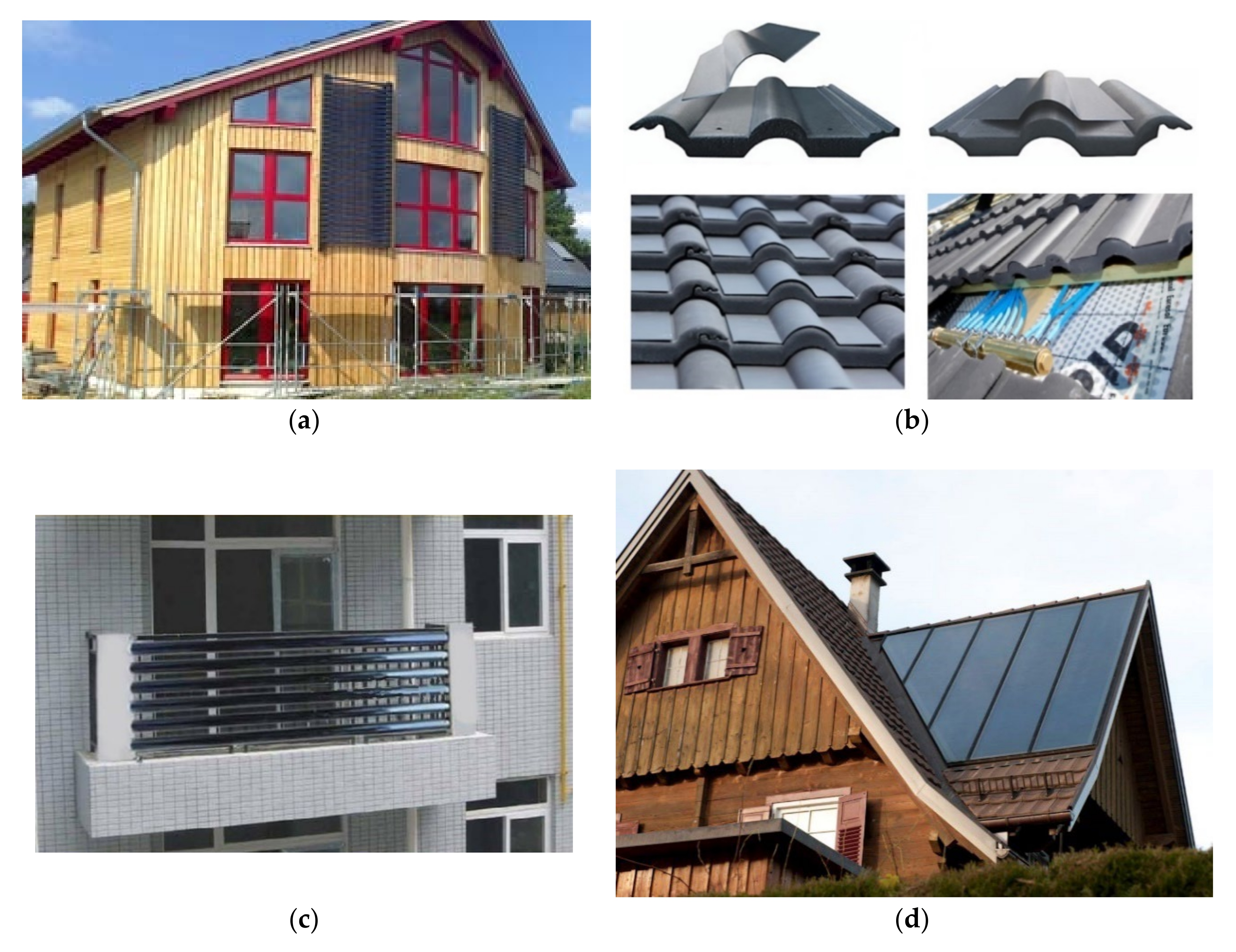
Solar thermal collectors (STCs) can be either integrated directly into the building elements, substituting conventional roof or façade cover materials, or constitute independent devices added on roof or façade structure (Figure 1). In both cases, they each strongly influence the building appearance. Any device, whether building integrated or not, should offer structural integrity and protection from wind, uncontrolled rainwater, and moisture penetration. STC systems able to ensure pleasant architectural integration in the context of the building, raising its architectural quality, must have materials, colors, shape, and size that adapt well to the overall modularity, creating an aesthetic appearance harmonized with the building itself. The presence of the glass cover on the collectors tends to reflect sunlight at certain times of the day, causing possible glare problems. The use of dummy elements also becomes relevant on the non-exposed surface of the façade or roof according to the design characteristics. Finally, they should become multifunctional construction elements resulting in public acceptance, thermal performance, aesthetics, and cost effectiveness [19]. Generally, it is possible to say that both concerns of maximizing solar energy spread and protecting the architectural quality of the built environment are justified, and both should possibly be satisfied at the same time, even in very critical contexts, under the condition that appropriate design and cost investments are made [20].
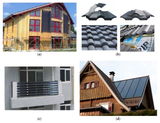
Figure 1.
Example of customization of solar collector: (a) shortened tubes on the façade (b) collectors on roof tiles, (c) balcony solar water heater (Hurras®), and (d) specially made glazed collectors on roof (Domasolar®).
Development of technologies, materials, support systems, and coatings has made the integration of STC systems into façades, sloping walls, roofs, shading devices, balcony railings, and curved/flexible façade and roof surfaces possible. The industrial effort connected to a further shape variation of the collectors, through the creation of curved or non-rectangular absorbers, must always be evaluated, and in any case, it remains limited to unglazed collectors. In some cases, the limits induced by the building geometry, can be solved by skillful design and appropriate features/devices (booster) as shown in [21]. Concerning the architectural quality, the integration is aimed at overcoming the dichotomy among the usual strategies of “exposure” and “hiding” [22] of solar installations as a free interpretation of the concept of “form of energy” [23], made possible both by products and innovative systems from the technological point of view that from not ordinary integration possibilities. About that, the visibility or invisibility of joints, surface colors and textures has not to be overlooked.
Customization
Colored absorbers, actually available on the market, can make an important contribution to the aesthetic integration in building facades. Recent studies [24] have shown interesting results with colors including blue, red-brown, green, or others. On the other hand, they are characterized by a lower thermal efficiency than the usual black type collectors because of the lower collector absorbance (α = 0.85). They consequently require larger surface areas and higher costs, but the results obtained for multi-flat residential or office buildings confirm their excellent capacity for capturing solar energy [25]. The fact that the integrated black collectors are still the most popular solution demonstrates that integration issues are much more complex than just choosing an appropriate colored absorber [3]. Instead of highly conductive metals and in order to improve integration in the facade, ceramics [26,27,28], polymers [29], and high capacitance materials [30] were also tested as absorber material. Even if characterized by low costs, they still show low conductivities (about 2 W/mK) and therefore must be carefully evaluated in terms of surface available for solar collection. The solutions involving the use of collectors whose shape and color correspond to the roof tile typology are also very interesting especially for restricted buildings roofs [31]. In this case, pans and collectors can be delivered fully assembled, so that the installation is not too complex or expensive (Figure 1b).
The vacuum systems constitute a mature technology and easily adaptable to the various configurations—from flat roofs to pitched roofs, from facades to free installation. In this category, the heat pipes show good energy performance, but they need to be installed with a minimum inclination of 25° to ensure correct circulation of the heat transfer fluid, leading to building integration issues. Factory-made modules are easy to assemble, with or without gaps, to ensure the desired transparency (Figure 1c), with unlimited expansion possibilities. Modern vacuum solar systems use an internal absorber plate that can be rotated according to the height of the seasonal sun and guarantying a significant increase in performance on an annual basis [32]. This is an example in which technology is driven to maximize energy efficiency without compromising the aesthetics of the solar collector-building combination. The same approach has led to a range of design strategies pointing out to a perfect mimesis of solar system placed onto roof, on the façade of buildings, in the shadings, or in accessories and protection elements as balustrades.
Roof Integration
For the roof, as for the facades, the shape, color, type and quality of the materials uniquely identify the building appearance. The use of STC systems should improve its architectural character without affecting its normal protective function from precipitation, wind and, in cold climates, from the weight of snow, sleet and ice.
In the residential complex at Hamburg-Bramfeld completed in Germany in 2000 (Figure 2), the 2920 m2 (2.04 MW) of STCs are perfectly integrated into sloped roofs of 123 terraced houses. The system is made by multi-layered elements that are prefabricated and installed providing all protection and insulation needs. A ground buried concrete tank with a water volume of 4500 m³ was charged to deliver heat for space heating and domestic hot water preparation for all the residential buildings in the district. In this case, the building is strongly characterized on the formal side by the presence of integrated STCs in a kind of technological “totem” constituted by the façade being strongly tilted; this element, even if separate from the rest of solar installations, acquires a meaningful iconic significance, highlighting the ecological qualities of the whole complex.

Figure 2.
Terraced houses in Hamburg-Bramfeld, Germany, 2000.
Façade Integration
Facade collectors are less sensitive to weather influences, since there is practically no loss of performance due to dirt and snow when installed vertically. With this installation variant, the issues of supply and rear ventilation must be considered in the early planning phase, keeping in mind that (i) the installation on the facade tends to be more and more effective in multi-family buildings with a relatively high number of floors and (ii) allows for an almost uniform annual solar radiation on the collectors, to the advantage of the winter months, with the maximum heat demand for space heating. Research in recent years in this regard has mainly focused on the transparent cover with colors having a high transmittance in the solar spectrum but a narrow peak of reflectance in the visible spectrum. Good results have been obtained for thermal floor systems by the deposition of thin films or with sol-gel coating [33,34]. However, even in this case, the authors point out that the most architecturally accepted lighter colors do not always correspond to more energy-efficient solutions.
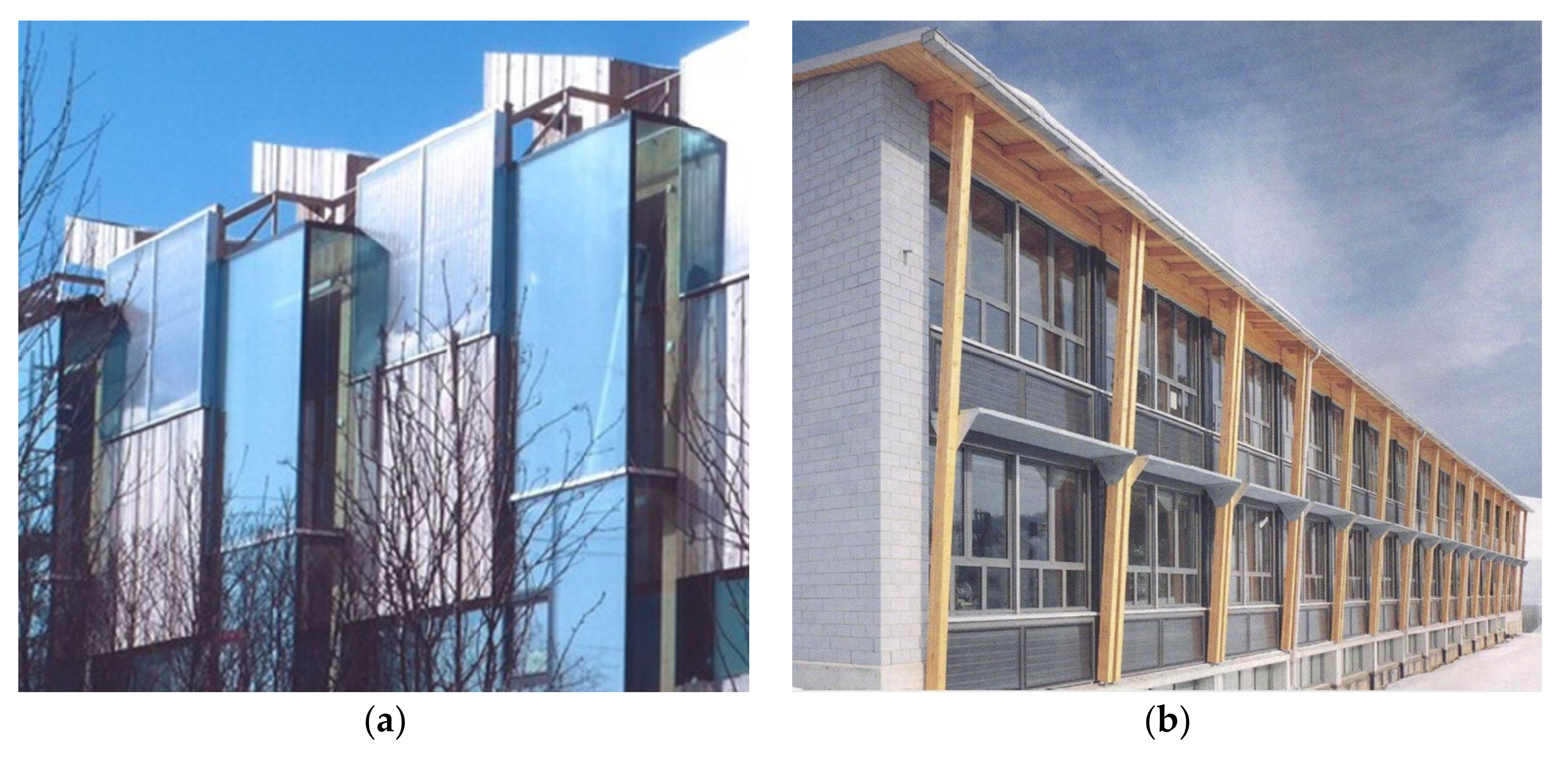
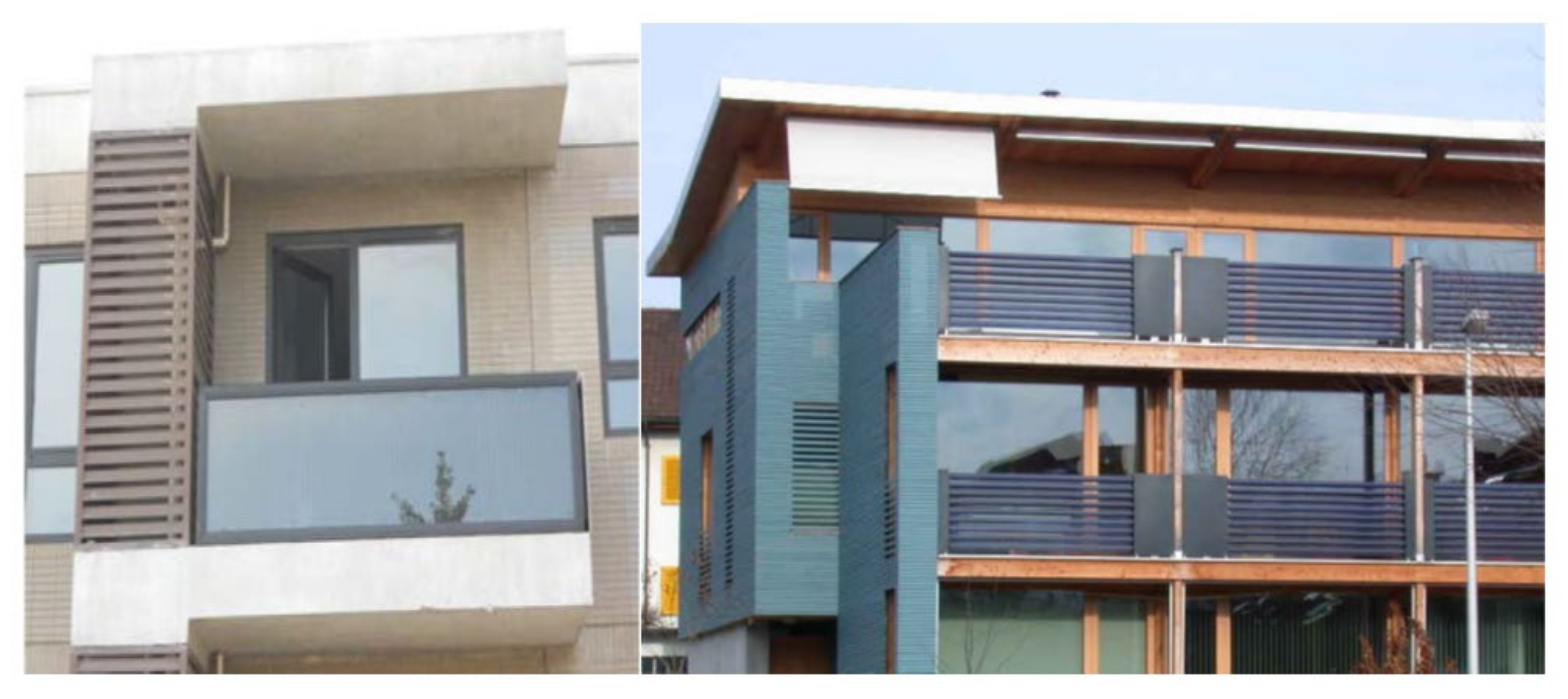
It is clear that these statements should be evaluated on a case-by-case basis, also taking into account the influence of latitude on the real energy savings and comparing the results with the same area with optimal inclination. As for example, the use of solar collectors to replace shading elements could be harmful if the decrease in solar gains on the windowed components is not taken into account. In the residential complex in Storelva-Tromsoe, 35 m2 of glazed collectors integrated in the south façade (Figure 3a) have been coupled with a heat pump to contribute to domestic hot water pre-heating mainly during spring, summer and autumn. The use of wood in the cladding of the envelope strongly highlights the presence of solar modules, ending up characterizing the entire building architectural aspect. In the school building in Geis, Switzerland (Figure 3b), 63 m² of glazed collectors integrated in the south facade guarantee an energy production of about 20,000 kWh/year. In this case, the integration is achieved through the modular repetition of frames and collectors.
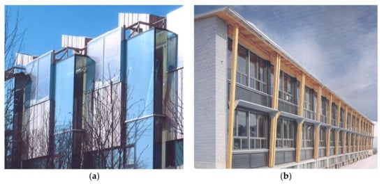
Figure 3.
Integration on façade with glazed flat plate collectors: (a) residential complex in Storelva-Tromsoe and (b) school building in Geis, Switzerland.
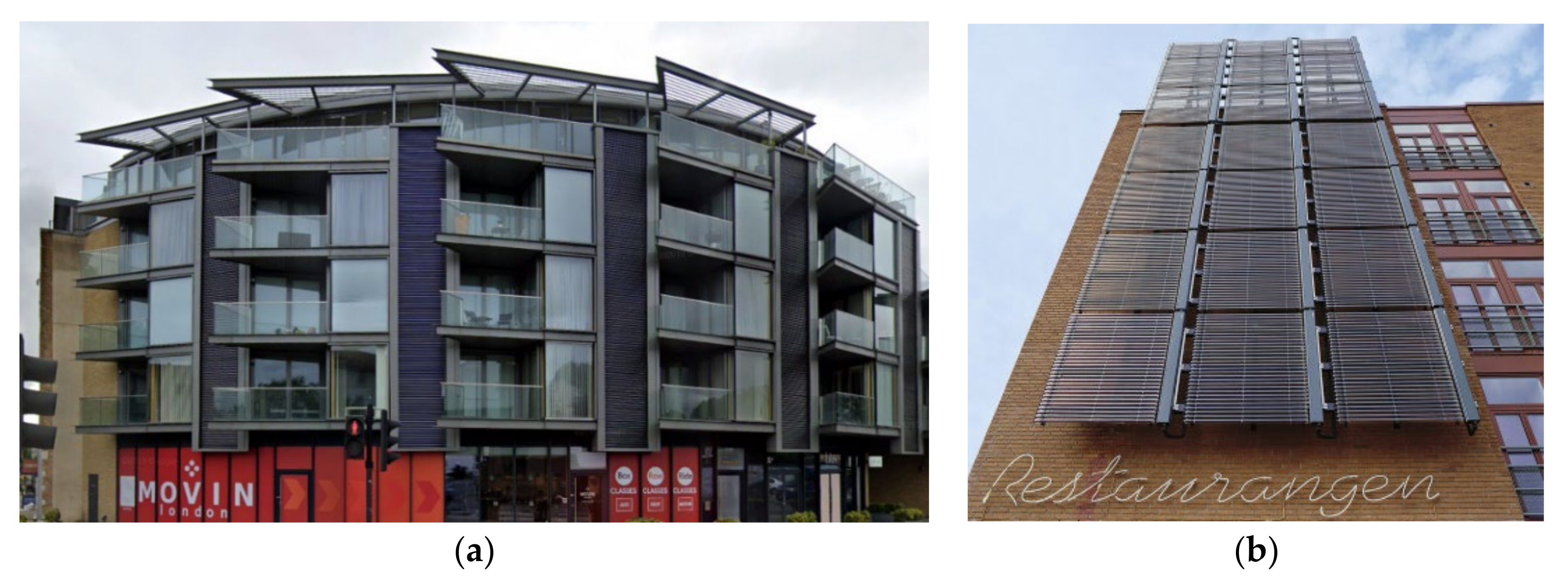
In the five-story residential building in Camden, London (Figure 4a), 93 m2 of evacuated tube collectors (Kingspan Varisol) are fully integrated in the facade giving the building a unique look, saving more than 5000 m3 of gas for year. Here, the building curvature was overcome by placing the collector tubes within six vertical banks, while the custom variable number of tubes has ensured that the installation exactly matches the irregular space of the banks to be filled. On the other hand, in the former port area of Malmö, Sweden (Figure 4b), there is an example of integration that is not fully successful from an aesthetic point of view but is functional for hot water production for sanitary use and for heat exchangers. Due to the high wind load, special stainless-steel supports have been used for the installation of collectors.
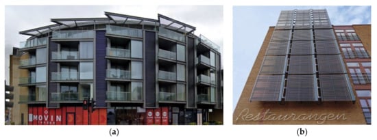
Figure 4.
Integration on façade with vacuum tube collectors in residential buildings in London (a) and Malmö, Sweden (b).
Shading Element on Facade
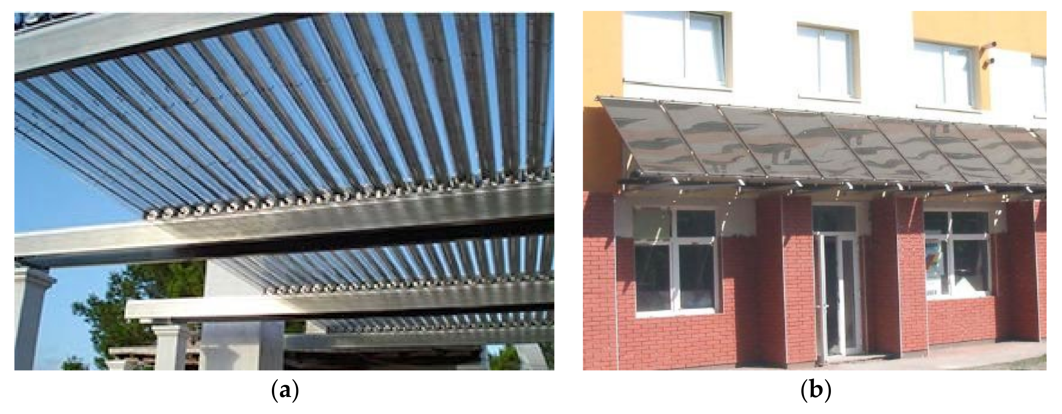
Design solutions using STCs as ledges for the shading of building elements are starting to spread. In this case, while flat glazed systems require compliance with the overall dimensions and can only adapt to sloped or horizontal ledges above window, they show increased protection from rain and snow. On the other hand, evacuated tube collectors can be installed as horizontal ledges above windows or like shading screen with horizontal, vertical, or sloped (inclination angle 0–90°) installations (Figure 5), although issues relating to their physical strength must be considered.
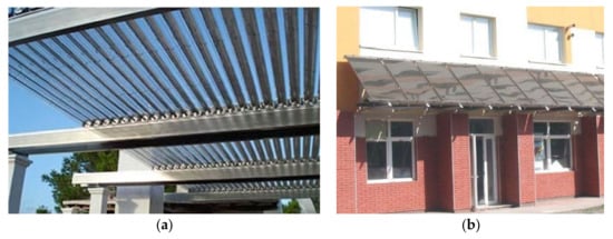
Figure 5.
(a) Evacuated tubes collectors used as deck sun shading and (b) glazed collectors used as overhang.
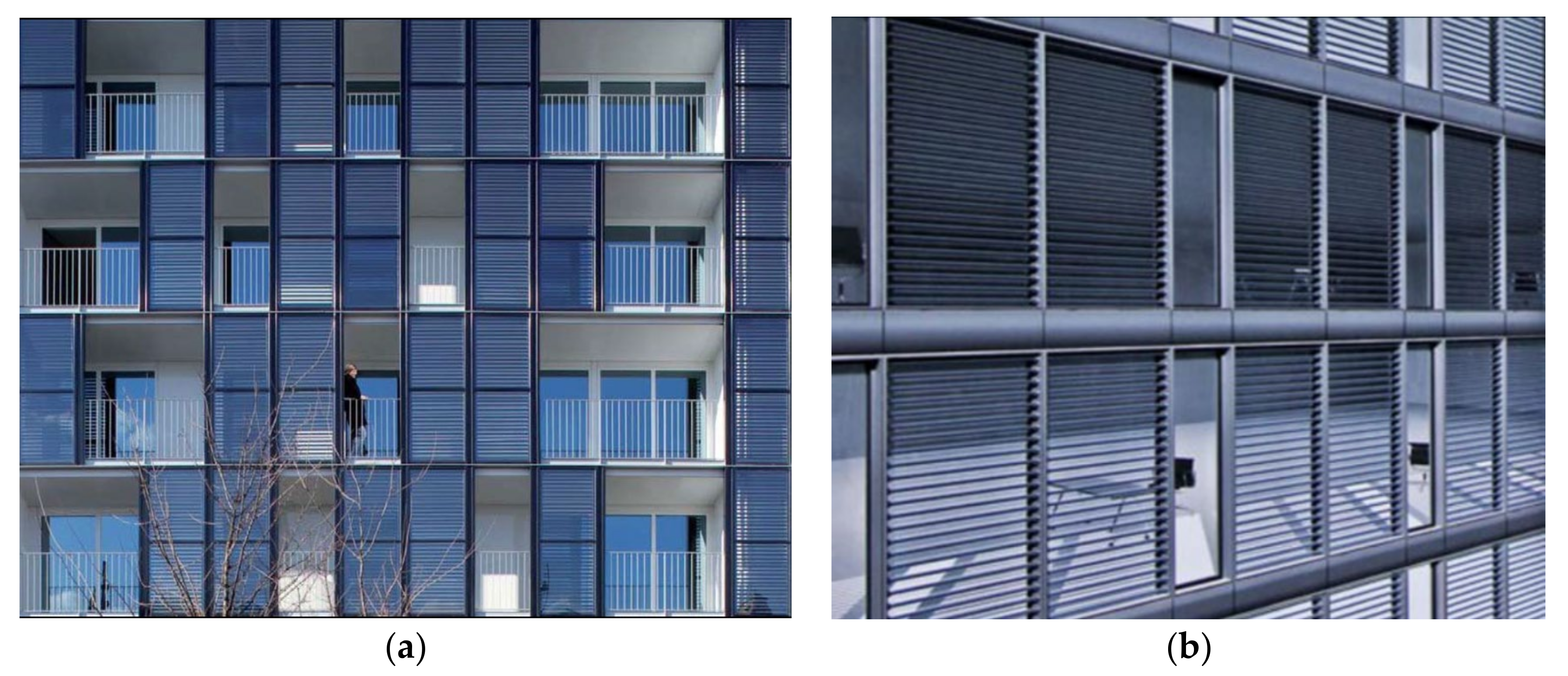
A successful experiment of social housing building with a facade made of solar panels has been carried out in Paris by the agency Philippon-Kalt Architects. The solar panel façade (Figure 6) traps solar energy to produce enough power to meet 40% of the DHW needs. Double-skin tinted solar panels are installed in an asymmetrical pattern, with the dual function of providing privacy and shade for the balconies, acting at the same time as an acoustic insulation.
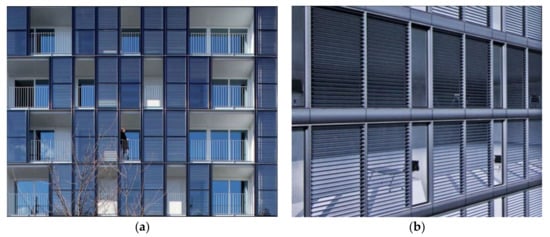
Figure 6.
(a) Philippon-Kalt Architectes Public House; (b) evacuated tube collectors shading open spaces terraces and balconies.
Substitution of Frames and Balustrades
As regards the use of collectors on balconies (Figure 7), the main problem is not their architectural integration but rather the destination of a space for the DHW storage tank. It can be placed on the same balcony, possibly shielded by means of specially integrated elements or inside compartment by using furnishing systems possibly integrated with heat pumps.
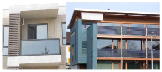
Figure 7.
Glazed and evacuated tubes collectors used as balcony balustrades.
A recent commercial application is represented by the introduction of forced circulation system with vacuum tube collectors on balconies of individual villas where conventional rooftop water heaters were not adaptable. The Solar Water Heating System (SWHS) ranges from 150 L to 250 L per day and consist of heat pipes with a small gradient to allow the fluid to move inside. The resulting efficiency was reduced up to 20 %, in respect to vertical orientation. To get the desired quantity of water, the STC size can be increased proportionally, which results in an increase of investment costs, too.
The Assessment of Integration Level
In general, the presence of constraints in the building architecture, in the context in which it is positioned (shading, climate) or in the existing heating system (for retrofit projects) makes SWHS integration design particularly complex, having to satisfy contrasting energy, aesthetic, economic and functional requirements. In [20] an evaluation method to help authorities to tailor solar energy promotion policies was proposed. The method introduced both the concept of “architectural criticity” of city surfaces, in relation to their need for integration quality and the concept of “architectural integration quality.” In this case the effort was to help define energy policies able to preserve the quality of pre-existing urban contexts while allowing solar energy use.
In order to achieve optimal solution, Krstic-Furundzic et al. [12] proposed an iterative procedure of design for integration of STCs into the envelope of a dormitory building, through an appropriate set of criteria including
- The climatic and urban planning criteria (global solar irradiance greater than 1500 kWh/m2, at least two roofs or two facades with favorable orientation)—From an energetic point of view, the energy produced will be proportional to the portion of the envelope available. The problem has different perspectives depending on whether it is a new construction (the expected energy needs require the available surfaces) or an energy retrofit (the available surface limits the amount of energy produced) [35,36]. Finally, placing solar thermal panels on periodically shaded surfaces of the building envelope could result in a lower system efficiency and cause damage from thermal stress resulting in glass cracks.
- Functional criteria—DHW systems electric-powered or centralized are better suited for integration with STC. The vacuum tube collectors are more efficient than the flat collectors but require greater system complication. Careful planning of the spaces intended for the storage tanks is required. The latter is a twofold problem, having to take into account that the STCs must be sized both according to the energy demand and also to the total storage capacity available in order to avoid damage resulting from overheating.
- Architectural criteria—The need to exploit the entire available surface with solar collectors, or to use dummy elements to ensure uniformity to the building appearance, generally requires the development of a specific and expensive customized product [36,37]. Reflections from the glass cover can cause undesirable glare. It must be borne in mind that its intrinsic characteristic of “transparency” can make visible the part responsible for absorbing solar energy, usually characterized by a sheet of copper, aluminum, or steel metal in a single piece or consisting of a row of metal strips. This problem is also present in vacuum tubes where both the absorbent metal strip inside and the rear reflective plates are always visible. “transparency” can make visible the part responsible for absorbing solar energy, usually characterized by a sheet of copper, aluminum, or steel metal in a single piece or consisting of a row of metal strips. This problem is also present in vacuum tubes, where both the absorbent metal strip inside and the rear reflective plates are always visible [37,38]. To date, the set of evaluation criteria proposed by Krstic remains the best attempt to standardize the level of architectural integration of solar systems.
3. Materials and Methods
The Potential Energetic Production in Urban Contexts
When the convenience of integrating solar panels in urban contexts with high building density have to be evaluated, the above mentioned criteria [12] become secondary to more general aspects such as (i) the presence and type of available roofs; (ii) the nominal yield of the solar modules; and (iii) the economic analysis (ie the payback time) for individual users (condominiums or single-family buildings). These aspects are partially considered in the GIS DB model mainly developed by the authors in [18] for the energetic exploitation of building roofs. It was here adapted and implemented in the Solar Analyst model developed by ESRI ArcGIS 10® in order to also evaluate the producibility on vertical surfaces, estimating in detail the different solar thermal potentials in an urbanized area, and comparing two different technologies (glazed and evacuated collectors) for different tilt angles.
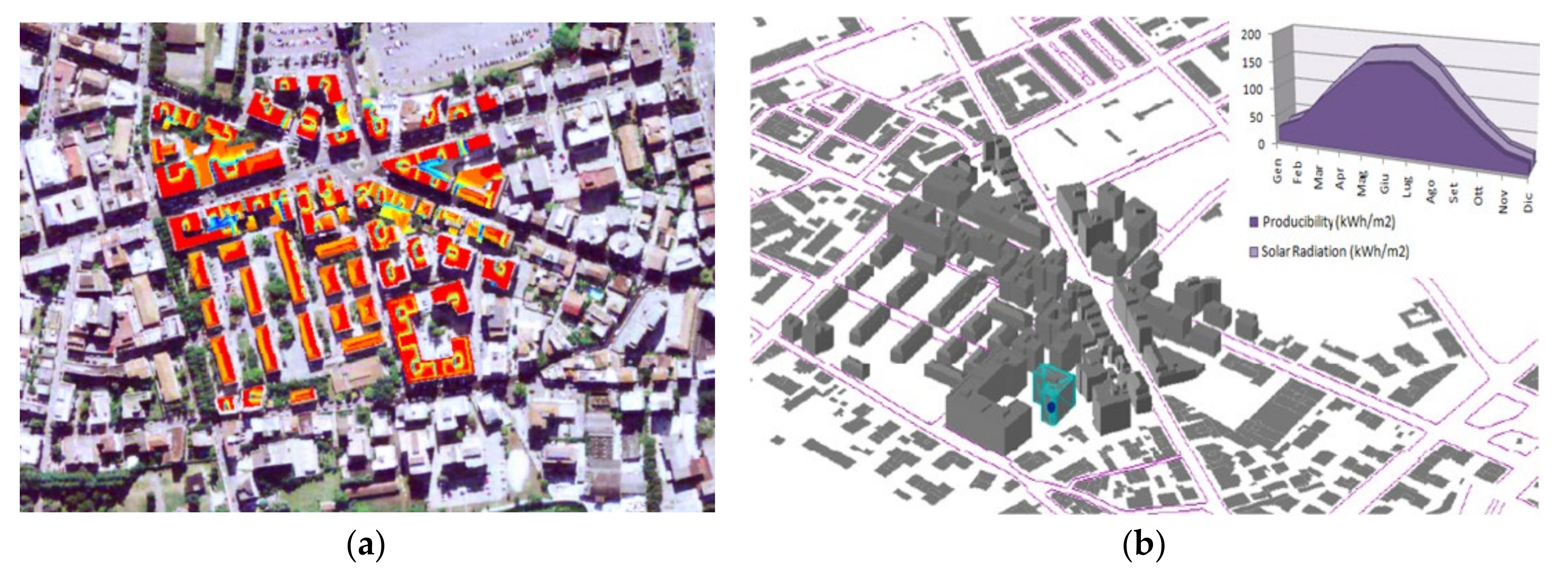
In particular, the model uses the functions and raster data-grid as tool to identify the roof typology from the average color of its pixels, as well as from the cross-check of the photogrammetric image with digital orthophotography (Figure 8), assuming an average roof slope of 30%.
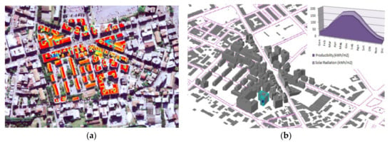
Figure 8.
(a) Roofs classification of residential units and (b) theoretical energy production of individual residential units (kWh/m2).
The presence of obstacles (e.g., windows, chimneys, and stairwells) causes a reduction of useful spaces for the installation of solar panels. In [39], as a general rule, a useful area of about 80% for flat roofs and 25% for pitched roofs is believed to be estimated.
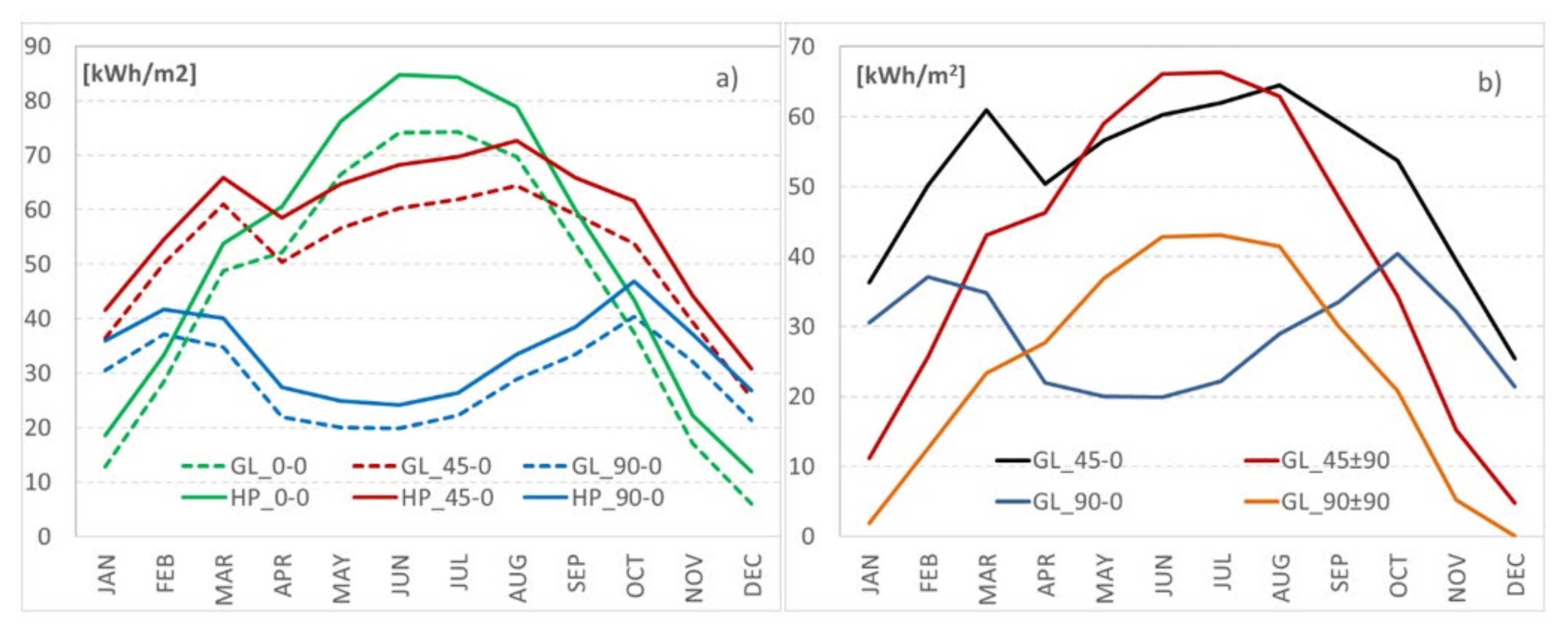
From a theoretical point of view, the optimal azimuth angle γ is the one orthogonal to the solar radiation direction. The plane collectors generally must be able to capture maximum energy by means of a fixed installation, representing the best compromise between the optimal exposure (e.g., independently from the roof inclination but at a disadvantage with respect to the general aesthetic) and the full building-collector integration. Although the variation of solar thermal systems production depending on tilt and azimuth angle is a well-known function, the energy contribution to simultaneous DHW production and heating has been reported in Figure 9 in order to evaluate the different contribution offered by glazed systems compared to heat pipe systems. In particular, Figure 9a compares the producibility per m2 of absorber surface for a glazed collector (GL) and a evacuated tube collector (HP) for an optimal azimuth angle (γ = 90 °) and for different possible installations on the building: β = 0° (shelters), 45° (shading systems), and 90° (balcony or vertical shading systems).
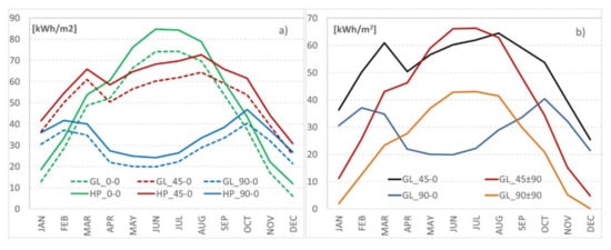
Figure 9.
Monthly averaged contribution to domestic heat water (DHW) production and heating for (a) glazed collectors (dashed lines) and evacuated tube collectors (continuous lines) with azimuth angle γ = 0° and different tilt angles β = 0°, 45°, and 90°; and (b) glazed collectors with azimuth angle γ = 0° and ±90° and tilt angles β = 45° and 90°.
For many of the architectural solutions exposed above, detailed information on their performance and design characteristics were not available, making their use impossible in the potential analysis of energy production in a highly urbanized context. The simulations were carried out on two types of collectors available on the market whose main energy and dimensional characteristics are summarized in Table 1.

Table 1.
Solar collectors’ models used in the simulation.
It is possible to observe how a 45° installation is quite optimal for the considered latitudes, with a decrease in the annual performance of the system between 11–14%, respectively, for HP and GL collectors for horizontal installations (0°) and a decrease of about 36% for both types of collectors for 90° installations. The difference between the two systems, in terms of average annual energy produced, results always greater than 13%, to the advantage of HP, with peaks of about 18% for vertical installations.
Figure 9b shows the producibility per m2 of absorbent surface for a glazed collector (a vacuum system has similar trends but with different percentages) in the case of 45° and 90° installations with an azimuth angle of ±90 °. These values are compared with the respective optimal azimuth values. It is possible to underline how, the East or West orientation of the panels leads to higher production in the summer months from April to September, due to a lower height of the sun in the hours of greatest solar exposure of the panels. As regards the annual producibility, there is in any case a decrease in the annual performance of the System between
- -
- 19÷ 22%, respectively for HP and GL collectors and 45° installation;
- -
- 13÷ 17%, respectively for HP and GL collectors and 90° installation.
It should be borne in mind that, especially in areas characterized by heavy snowfall, the greater the slope of the pitch, the easier it is for the snow to slide from the flat collectors installed on it. In this regard, it should be noted that evacuated pipes, due to their shape and heat retention, take longer to make snow fall [41].
The Case Study
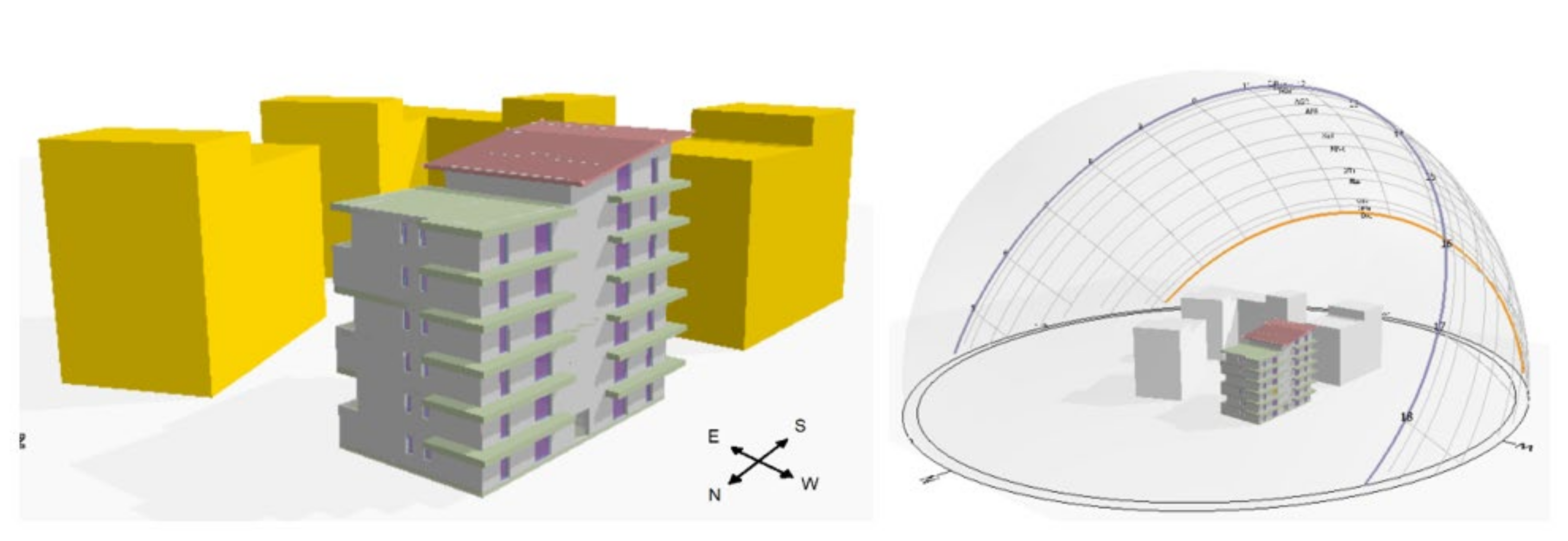
The impossibility of using horizontal or inclined pitches on condominium buildings in highly urbanized contexts, makes the possibility of using the collectors as integrated casing elements on the facade particularly attractive. In this case, the inclination (90°) and the azimuth angle (facade exposure) represent technical constraints: the producibility must be estimated only on the basis of the available surfaces, which in turn are bound to the availability of well exposed opaque walls or balconies/window elements on which shielding elements could be installed. In order to estimate the real producibility of solar systems for DHW production or for heating integration, the possibility of exploiting glazed and vacuum collectors on the side walls of a condominium building is analyzed. The roof is not used because, due to its high potential in a Mediterranean region, the contribution to the thermal energy requirement would have neglected the results of integrated facade systems. The case-study building is part of the typical construction type of multi-story buildings characterized by the presence of balconies on the facades and portion of an opaque wall without windows on all the sides exposed to solar radiation (Figure 10 from East to West). The building is made up of five floors with a sloping roof of approximately 225 m2 and a horizontal coverage residential area of 134 m2 not usable for technical purposes. The building is partially shaded on the south side and on the east side by similar buildings in the immediate vicinity.
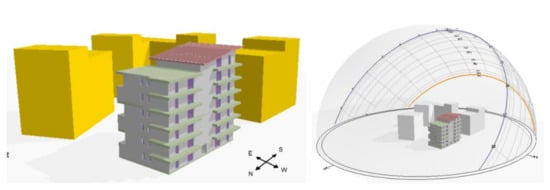
Figure 10.
Case-study building and related sun paths for radiative loads analysis.
The building envelope consists of opaque vertical walls (350 mm) in brick and external plastic insulation with an overall transmittance of 0.34 W/m2K. Double glazed windows and PVC frame with an average transmittance of 1.8 W/m2K are present. In order to take into account the different possibilities of capturing solar energy by the envelope, different azimuth exposures of the walls have been analyzed. A centralized system for space heating and DHW production with a 275-kW diesel-fueled boiler is available, while summer air conditioning is obtained by means of autonomous heat pump systems. The building is located in Cagliari (Italy), and its energy requirement is approximately 123 kWh/m2 corresponding to energy class F.
Simulations have been conducted using dynamic hourly simulation model implemented in the commercial software Thermolog®, developed by Logical Soft (Italy). The average hourly data (external air temperature, specific humidity, solar radiation, wind speed and direction) and the real conditions of use of the building were used as input data, specifying for each month the number of actual days and hours of air conditioning system operation. It was not possible to have a monthly feedback on the real energy consumption of the building, as the refueling of the diesel tank is generally carried out according to scheduled times but not associated with any measurement of the actual amount of diesel consumed.
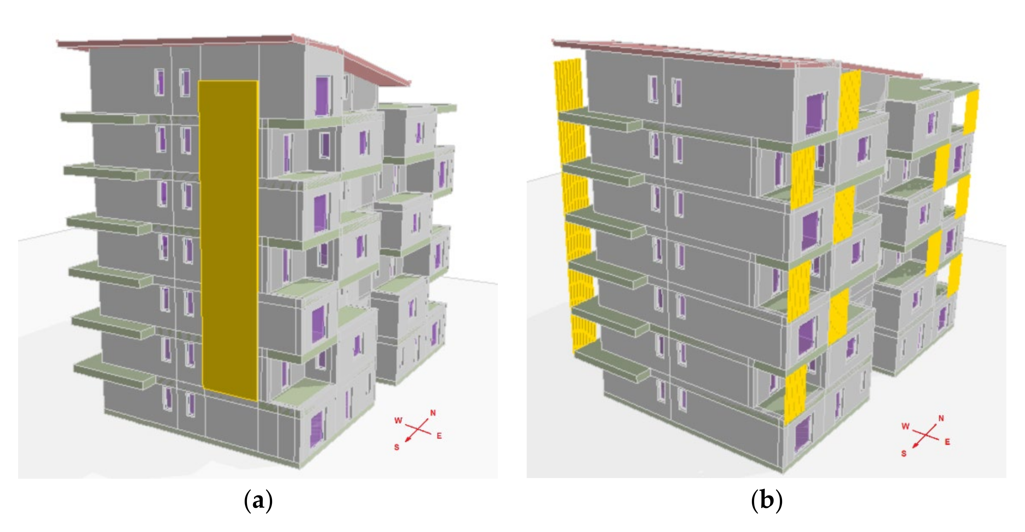
The exploitation of solar energy is obtained through two possible architectural interventions: (i) installation of 22 flat plate collectors (Vitosol 200 type model) on the opaque wall facing South (Figure 11a); (ii) installation of 22 evacuated-tube solar collectors (Vitosol 300 type model) as active shading elements in correspondence with the balconies placed on the walls facing East and West (Figure 11b).
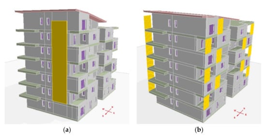
Figure 11.
Architectural integration with (a) glazed flat solar collectors on the south wall and (b) vacuum solar collectors as active shading elements for the windows exposed to East and West.
The building complies with the set of criteria proposed by [12] in order to have an optimal integration of STCs into the envelope. The building is located in Cagliari with an average annual irradiation on a horizontal surface equal to about 1620 kWh/m2. It presents two facades with a favorable orientation (East and South) without shading limitations, and another facade (West) partially shaded by the neighboring buildings. The building is relatively new, so the available surfaces do not limit the amount of energy produced and presents a centralized system for DHW production, particularly suitable for integration with solar thermal systems. As regards the architectural aspects, the vacuum collectors chosen for the analysis replace at best shading elements on balconies, generally made up of parallel, adjustable, or fixed slats, and are arranged so as to give continuity to the building architecture (see Figure 11).
4. Results and Discussion
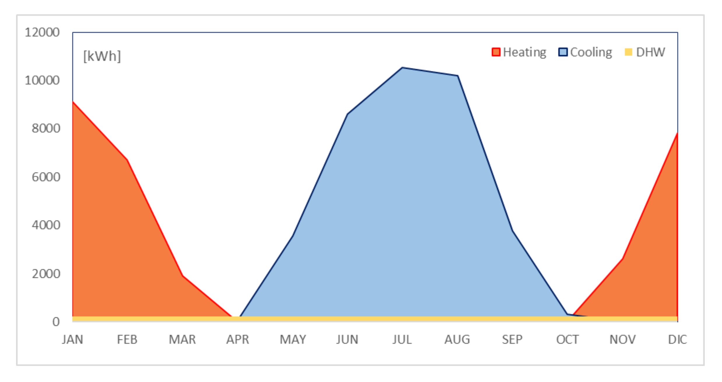
Figure 12 shows the monthly energy requirement for heating, cooling and DHW for the case-study building. It represents the reference scenario in our simulation. The heating primary energy consumption occurs from November to March, while the cooling period occurs from May to September. DHW production is almost constant and equal to about 233 kWh/month.
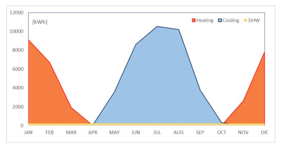
Figure 12.
Monthly energy needs for space heating, cooling, and DHW for the case-study building.
In order to evaluate the contribution of STC on the above-mentioned monthly energy need, different scenarios have been investigated. They are summarized in Table 2, where they are reported, respectively, as the relative identification number in column 1, the type of STC used in column 2, the façade on which the STC are installed in column 3, and the STC service purpose in column 4. For the sake of clarity, in Scenario #2, the use of 22 flat plate collectors, mounted on the opaque wall south faced and used only for DHW, has been simulated. The use of evacuated collectors on the south façade was not taken into consideration because the expected difference in terms of their producibility is well known in the literature and already estimated in Figure 9a (tilt angle β = 90°). The roof is not used because, due to its advantageous exposure and inclination, the contribution to the thermal energy requirement would have neglected the results of integrated facade systems, in particular for those systems whose contribution is quite low (collectors on the opaque wall used only for DHW production). Finally, the choice of vacuum collectors as shielding elements (and not glazed ones) is attributable solely to architectural reasons, as above specified.

Table 2.
Investigated integration scenarios.
In Scenario #4, the same STC are used both for DHW production and space heating. For all scenarios from # 2 to # 8, the use of a 5000-litre storage tank is foreseen in the central heating room and used for space heating and DHW production.
Scenario #3 is aimed at estimating how much the orientation of the building affects the contribution obtainable from the solar thermal system. The 22 flat plate collectors are always mounted on the same opaque wall, but the building is rotated with respect to the reference Scenario #1, so the “active façade” is now faced to the East (or to the West).
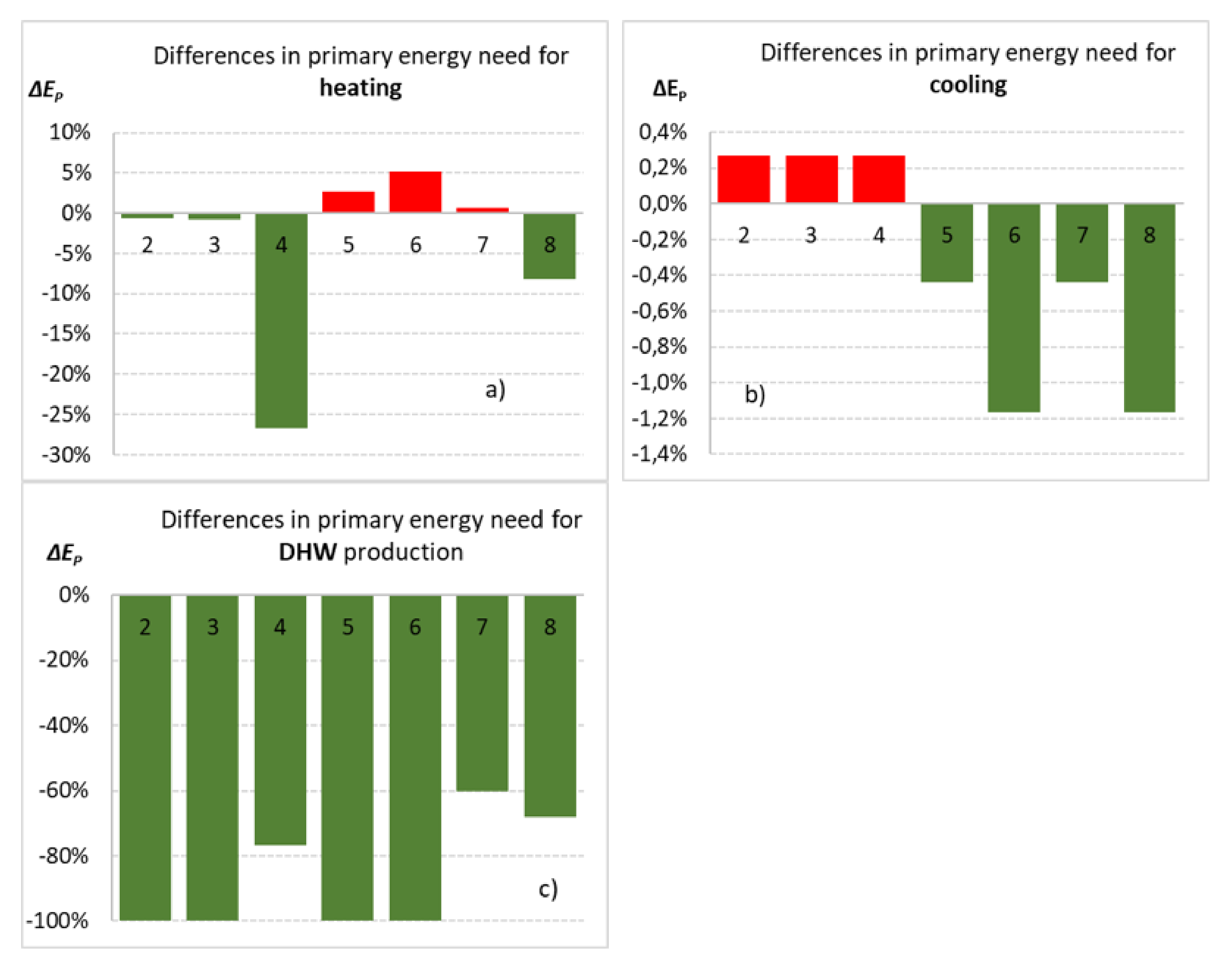
In Table 3 and Table 4, the monthly primary energy need (kWh/month) for heating and DHW covered by the traditional diesel boiler are reported for the eight investigated scenarios. In Table 5, the monthly primary cooling energy need (kWh/month) covered by the autonomous heat pumps are reported for the eight investigated scenarios. Figure 13 shows the differences, between the seven (i = 1 to 7) scenarios analyzed and the reference one, in terms of building primary energy needs (Ep), respectively for heating (Figure 13a), cooling (Figure 13b), and DHW production (Figure 13c), The differences are reported in percentages, according to

Table 3.
Monthly thermal energy requirement (kWh/month) for heating, covered by the traditional generator for the different scenarios.

Table 4.
Monthly thermal energy requirement (kWh/month) for DHW production, covered by the traditional generator.

Table 5.
Monthly thermal energy requirement (kWh/month) for cooling, covered by the traditional generator.
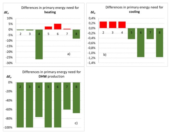
Figure 13.
Differences in primary energy need for each scenario respect to the reference one.
As regards cooling energy requirements (Table 5), the almost zero contribution provided by the solar system in all scenarios is evident. The high difference recorded in the Scenario #3 is attributable only to the rotation of the building (+90° or −90°) and to the fact that one of the windowed walls is now unfavorably North exposed.
As regards the scenarios in which STC are used only for DHW production, it can be pointed out that the expected benefits on the transmittance of the opaque envelope, due to the increase in thermal resistance by the presence of the collectors, are completely negligible, allowing a decrease (increase) in energy needs for space heating (cooling) in winter (summer) that is always less than 1%. This is presumably due to the low transmittance of the original opaque envelope and to the low percentage of surface coverage not exceeding 10% of the same envelope. On the other hand, all these scenarios provide 100% of the DHW demand in all months of the year.
The use of solar collectors to replace shading elements is even worse if used only for DHW production. The decrease in solar gains on the windowed components of the East wall (Scenario #5) or on both the East and West walls (Scenario #6) determines an increase in winter requirements of 2.6% and 5.2%, respectively. The benefit in terms of reducing the solar load for cooling in summer is negligible in the first case (Scenario #2) and slightly higher than 1% in the second case.
The benefits become significant only if collectors are also used to meet winter energy needs. In this case, the use of flat plate collectors on the South facade (Scenario #4) leads to a reduction of the winter primary energy need (respect Scenario #1) of 26.7%. The use of evacuated-tube collectors to replace shading elements on a single facade of the building (East in Scenario #7) is not very significant in terms of reduction of free heat gains (approximately +0.6% in winter and −0.4% in summer). On the contrary, the arrangement of collectors on both sides East and West (Scenario #8) leads to a decrease in the primary energy need in winter and in the summer requirement by just above 8% and 1%, respectively. In these three scenarios, the complete satisfaction of the DHW production in the winter months will not be achieved, and the integration from traditional generator, respectively, for 23% (Scenario #4), 40% (Scenario #7), and 32% (Scenario #8) will be necessary.
5. Conclusions
Solar thermal systems have been developed as pure technical elements to make use of solar energy to contribute to space heating and DHW production. However, these active elements should be integrated into the architectural framework of the building so as not to contribute to the decay of its overall architectural character. Recent developments in technologies, materials, support systems, and coatings have made it possible to get effective integration of solar thermal systems into façades, sloping walls, roofs, shading devices, balcony railings, and curved/flexible façade and roof surfaces.
In buildings, the visible parts of the roof and façade are best suited for this kind of integration. STC systems show less integration ability respect to PV systems, thus they need specific attention in design, manufacture and installation stages in order to achieve the best architectural integration in terms of size and position, color, surface texture, and materials and module jointing. The aesthetics and building envelope performance of these “building integrated systems” can match that of existing buildings and therefore promote their adoption by owners, also providing substantial savings from reduced heating, maintenance, and repair costs.
The authors focused the attention on the possible savings achievable in terms of primary energy required for a condominium building equipped with a traditional generator and located in a highly urbanized context, in the Mediterranean climate. It is possible to point out that the use of solar thermal systems as architecturally integrated elements on the opaque walls of the building does not lead to appreciable differences in terms of thermal insulation of the envelope. In the investigated building, a percentage of opaque walls of less than 10% and no additional dummy elements were considered to cover the facade. The exploitation of the facades available for the installation of solar collectors always results in a substantial saving in terms of primary energy need for DHW production. It is generally achieved by solar thermal system for more than 60% (when the system is used also for space heating) or equal to 100% (when the system is used for DHW production only). On the other hand, the use of solar collectors to replace shading elements is generally detrimental when they are used only for DHW production. The decrease in solar gains on the windowed components determines, in fact, an increase in winter needs always higher than 2.5%. The benefits become appreciable only if the solar collectors are used also for winter space heating. In this case, the use of solar collectors leads to a reduction in the winter primary energy need from a traditional generator of above 20% for collectors installed on opaque south walls and below 10% for collectors used as shading elements.
Although the results presented in this paper are strictly linked to the climatic context chosen as a reference (Mediterranean) and to the types of collectors used in the simulation, they constitute the first step of a basic research that aims to evaluate the real convenience of solar collectors’ architectural integration. For this reason, the study will be further explored in the near future by the authors to take into account the mutual conflict existing between energy performance, functional–aesthetic, ecological (minimum environmental criteria), and economic aspects (total cost of SWHS integration, maintenance cost, etc.), evaluating the effect produced by different latitudes, age of the building and other influencing factors on the above discussed results.
Author Contributions
Study conception and design: A.F., G.F., and M.D.; Acquisition, analysis, and interpretation of data: A.F. and C.C.M.; Drafting of manuscript: A.F., G.F., and L.C.; Critical revision: G.F. and M.D. All authors read and approved the manuscript and author contributions
Funding
This research received no external funding
Conflicts of Interest
The authors declare no conflict of interest.
References
- Hestnes, A.G. Building integration of solar energy systems. Sol. Energy 1999, 67, 181–187. [Google Scholar] [CrossRef]
- Voss, K. Solar energy in building renovation—Results and experience of international demonstration buildings. Energy Build. 2000, 32, 291–302. [Google Scholar] [CrossRef]
- Munari Probst, M.C.; Roecker, C. Towards an improved architectural quality of building integrated solar thermal systems (BIST). Sol. Energy 2007, 81, 1104–11169. [Google Scholar] [CrossRef]
- Arpino, F.; Cortellessa, G.; Frattolillo, A. Experimental and numerical assessment of photovoltaic collectors performance dependence on frame size and installation technique. Sol. Energy 2015, 118, 7–19. [Google Scholar] [CrossRef]
- Reinberg, G.W. Architetture; Alinea: Florence, Italy, 1999. [Google Scholar]
- IEA. Advanced Solar Domestic Hot Water System; Report of Task 14; IEA: Paris, France, 1996. [Google Scholar]
- IEA. Solar Energy in Building Renovation; Report of Task 20; IEA: Paris, France, 1998. [Google Scholar]
- IEA. Optimization of Solar Energy Use in Large Buildings; Report of Task 23; IEA: Paris, France, 2000. [Google Scholar]
- Buker, M.S.; Riffat, S.B. Building integrated solar thermal collectors—A review. Renew. Sustain. Energy Rev. 2015, 51, 327–346. [Google Scholar] [CrossRef]
- Bock, M. A building integrated solar thermal collector with active steel skins. Energy Build. 2019, 201, 134–147. [Google Scholar] [CrossRef]
- Krstic Furundzica, A.; Kosoricb, V.; Golicc, K. Potential for reduction of CO2 emissions by integration of solar water heating systems on student dormitories through building refurbishment. Sustain. Cities Soc. 2012, 2, 50–62. [Google Scholar] [CrossRef]
- Protection of Natural Beauty, Italian Law of 29 June 1939, n. 1497. Off. Ital. Gazzette 2004, 45. Available online: https://www.gazzettaufficiale.it/eli/gu/2004/02/24/45/so/28/sg/pdf (accessed on 23 October 2020).
- European Council. Directive 2010/31/EU of the European Parliament and of the Council of 19 May 2010 on the energy performance of buildings. Off. J. Eur. Union 2010, 153, 13–35. [Google Scholar]
- European Union. Directive 2012/27/EU of the European Parliament and of the Council of 25 October 2012 on energy efficiency, amending Directives 2009/125/EC and 2010/30/EU and repealing Directives 2004/8/EC and 2006/32/EC. Off. J. Eur. Communities OJL 2012, 315, 1–56. [Google Scholar]
- European Community. Directive (EU) 2018/844 of the European Parliament and of the Council of 30 May 2018 amending Directive 2010/31/EU on the energy performance of buildings and Directive 2012/27/EU on energy efficiency. Off. J. Eur. Union 2018, 156, 75–91. [Google Scholar]
- Transposition of the European Directive 2009/28/EC on the Promotion of the Use of Energy from Renewable Sources; Italian Legislative Decree 28/2011. Off. Ital. Gazzette 2011, 71. Available online: https://eur-lex.europa.eu/legal-content/EN/ALL/?uri=CELEX%3A32009L0028 (accessed on 23 October 2020).
- Code of Cultural Heritage and Landscape; Italian Legislative Decree, 22 January 2004, n. 42. Off. Ital. Gazzette 2004, 45. Available online: https://whc.unesco.org/document/155711 (accessed on 23 October 2020).
- Massimo, A.; Dell’Isola, M.; Frattolillo, A.; Ficco, G. Development of a geographical information system (GIS) for the integration of solar energy in the energy planning of a wide area. Sustainability 2014, 6, 5730–5744. [Google Scholar] [CrossRef]
- Buonomano, A.; Forzano, C.; Kalogirou, S.A.; Palombo, A. Building-façade integrated solar thermal collectors: Energy-economic performance and indoor comfort simulation model of a water based prototype for heating, cooling, and DHW production. Renew. Energy 2019, 137, 20–36. [Google Scholar] [CrossRef]
- Munari Probst, M.C.; Roecker, C. Criteria and policies to master the visual impact of solar systems in urban environments: The LESO-QSV method. Sol. Energy 2019, 184, 672–687. [Google Scholar] [CrossRef]
- Baccoli, R.; Frattolillo, A.; Mastino, C.; Curreli, S.; Ghiani, E. A comprehensive optimization model for flat solar collector coupled with a flat booster bottom reflector based on an exact finite length simulation model. Energy Convers. Manag. 2018, 164, 482–507. [Google Scholar] [CrossRef]
- Baird, G. The Architectural Expression of Environmental Control Systems; Spoon Press: London, UK; New York, NY, USA, 2001. [Google Scholar]
- Olgay, V. Design with Climate—A Bioclimatic Approach to Architectural Regionalism; University of Princeton Press: Princeton, NJ, USA, 1962. [Google Scholar]
- Kalogirou, A.S. Solar thermal collectors and applications. Prog. Energy Combust. Sci. 2004, 30, 231–295. [Google Scholar] [CrossRef]
- Tripanagnostopoulos, Y.; Souliotis, M.; Nousia, T. Solar collectors with coloured absorbers. Sol. Energy 2000, 68, 343–356. [Google Scholar] [CrossRef]
- Sun, X.Y.; Sun, X.D.; Li, X.G.; Wang, Z.Q.; He, J.; Wang, B.S. Performance and building integration of all-ceramic solar collectors. Energy Build. 2014, 75, 176–180. [Google Scholar] [CrossRef]
- Xu, J.; Yang, Y.; Cai, B.; Wang, Q.; Xiu, D. All-ceramic solar collector and all ceramic solar roof. J. Energy Inst. 2014, 87, 43–47. [Google Scholar] [CrossRef]
- O’Hegarty, R.; Kinnane, O.; McCormack, S.J. Review and analysis of solar thermal facades. Sol. Energy 2016, 135, 408–422. [Google Scholar] [CrossRef]
- Tsilingiris, P.T. Towards making solar water heating technology feasible—The polymer solar collector approach. Energy Convers. Manag. 1999, 40, 1237–1250. [Google Scholar] [CrossRef]
- D’Antoni, M.; Saro, O. Energy potential of a massive solar-thermal collector design in European climates. Sol. Energy 2013, 93, 195–208. [Google Scholar] [CrossRef]
- Baunetzwissen HomePage. Available online: https://www.baunetzwissen.de (accessed on 23 October 2020).
- Höchstleistung zu Jeder Jahreszeit. Available online: http://augusta-solar.com/hochleistungs-kollektoren (accessed on 23 October 2020).
- Schüler, A.; Boudaden, J.; Oelhafen, P.; De Chambrier, E.; Roecker, C.; Scartezzini, J.-L. Thin film multilayer design types for coloured glazed thermal solar collectors. Sol. Energy Mater. Sol. Cells 2005, 89, 219–231. [Google Scholar] [CrossRef]
- Dudita, M.; Manceriu, L.M.; Anastasescu, M.; Nicolescu, M.; Gartner, M.; Duta, A. Coloured TiO2 based glazing obtained by spray pyrolysis for solar thermal applications. Ceram. Int. 2014, 40, 3903–3911. [Google Scholar] [CrossRef]
- Visa, I.; Moldovan, M.; Comsit, M.; Neagoe, M.; Duta, A. Facades integrated solar-thermal collectors—Challenges and solutions. Energy Procedia 2017, 112, 176–185. [Google Scholar] [CrossRef]
- Lamnatou, C.; Cristofari, C.; Chemisana, D.; Canaletti, J.L. Building-integrated solar thermal systems based on vacuum-tube technology: Critical factors focusing on life-cycle environmental profile. Renew. Sustain. Energy Rev. 2016, 65, 1199–1215. [Google Scholar] [CrossRef]
- Prieto, A.; Knaack, U.; Auer, T.; Klein, T. Solar façades—Main barriers for widespread façade integration of solar technologies. J. Facade Des. Eng. 2017, 5, 51–62. [Google Scholar]
- Maurer, C.; Cappel, C.; Kuhn, T.E. Progress in building-integrated solar thermal systems. Sol. Energy 2017, 154, 158–186. [Google Scholar] [CrossRef]
- Cellura, M.; Guarino, F.; Longo, S.; Mistretta, M. Energy life-cycle approach in Net zero energy buildings balance: Operation and embodied energy of an Italian case study. Energy Build. 2014, 72, 371–381. [Google Scholar] [CrossRef]
- Energy Performance of Buildings—Method for Calculation of System Energy Requirements and System Efficiencies—Part 4–3: Heat Generation Systems, Thermal Solar and Photovoltaic Systems; UNI EN 15316-4-3:2018; Module M3-8-3, M8-8-3, M11-8-3; Italian Organization for Standardization: Milano, Italy, 2018.
- Appleyard, W.; Konkle, D. Making solar thermal fit in Ann Arbor’s 5000 solar roofs programme. Renew. Energy World 2007, 10, 80–86. [Google Scholar]
Publisher’s Note: MDPI stays neutral with regard to jurisdictional claims in published maps and institutional affiliations. |
© 2020 by the authors. Licensee MDPI, Basel, Switzerland. This article is an open access article distributed under the terms and conditions of the Creative Commons Attribution (CC BY) license (http://creativecommons.org/licenses/by/4.0/).

