Article

Hydrocracking of a Heavy Vacuum Gas Oil with Fischer–Tropsch Wax

1
Department of Petroleum Technology and Alternative Fuels, University of Chemistry and Technology, Prague 160 00, Czech Republic
2
Unipetrol, Centre for Research and Education, a.s., Litvínov 436 70, Czech Republic
3
Faculty of Agrobiology, Food and Natural Resources, Department of Chemistry, Czech University of Life Sciences Prague, Kamýcká 129, Prague 6, 169 21, Czech Republic
*
Author to whom correspondence should be addressed.
Energies 2020, 13(20), 5497; https://doi.org/10.3390/en13205497
Submission received: 23 September 2020 / Revised: 12 October 2020 / Accepted: 14 October 2020 / Published: 20 October 2020
(This article belongs to the Section B: Energy and Environment)

Abstract

:
Catalytic hydrocracking represents an optimal process for both heavy petroleum fractions and Fischer–Tropsch (FT) wax upgrading because it offers high flexibility regarding the feedstock, reaction conditions and products’ quality. The hydrocracking of a heavy vacuum gas oil with FT wax was carried out in a continuous-flow catalytic unit with a fixed-bed reactor and a co-current flow of the feedstock and hydrogen at the reaction temperatures of 390, 400 and 410 °C and a pressure of 8 MPa. The increasing reaction temperature and content of the FT wax in the feedstock caused an increasing yield in the gaseous products and a decreasing yield in the liquid products. The utilisation of the higher reaction temperatures and feedstocks containing the FT wax showed a positive influence on the conversion of the fraction boiling above 400 °C to lighter fractions. Although the naphtha and middle distillate fractions obtained via atmospheric and vacuum distillations of the liquid products of hydrocracking did not comply with the particular quality standards of automotive gasolines and diesel fuels, the obtained products still present valuable materials which could be utilised within an oil refinery and in the petrochemical industry.

1. Introduction

It only took approximately 150 years for petroleum to change our lives so significantly that it has become a global engine of the economy. Petroleum is one of the most important natural resources nowadays. Its global consumption is estimated to be 100 million barrels per day. The daily consumption is forecast to increase to ca. 105 million barrels in 2023, especially due to the increased demand and economic growth [1]. Although the most significant increase in the crude oil demand can be observed in the petrochemical industry, its largest consumption can still be found in the production of the liquid transportation fuels (diesel fuel, gasoline and jet fuel). Due to the limited petroleum sources, its increasing consumption and ever tightening legislative regulations and requirements related to global climate change and other negative impacts of the fossil fuels utilisation, it is becoming ever more crucial to find renewable energy sources. It could be considered as one part of the puzzle for a sustainable economy and long-term development [2,3,4].
The options for the utilisation of the commonly used liquid biofuels, such as alcohols (especially ethanol), biodiesel and vegetable oils, in the current engines are usually limited [5]. On the other hand, hydrocarbon-based fuels produced via XTL (X-to-liquids) technologies have good potential to become an important drop-in fuel. A rather wide portfolio of potential raw materials is one of the major advantages of these technologies. For example, natural gas (G), coal (C), biomass (B), but also other carbon-based materials like used tyres or even carbon dioxide could be found hidden under the (X) in the XTL abbreviation. The carbon-based raw material is firstly converted to a synthesis gas composed of hydrogen and carbon monoxide and the Fischer–Tropsch synthesis (FTS) is the key stage of each XTL process [6]. It involves heterogeneous catalytic reactions where the synthesis gas is transformed to a wide range of hydrocarbons. The product is free of sulfur, nitrogen, metals and other impurities. It can contain a low amount of oxygen-containing compounds. Atmospheric distillates from the FTS product can be directly used for the production of transportation fuels. The atmospheric residue of FTS consists of high molecular weight hydrocarbons and is called Fischer–Tropsch wax (FT wax). It can be processed via common refinery technologies like fluid catalytic cracking (FCC), hydrocracking or pyrolysis to increase the yield of the light fractions suitable for the production of transportation fuels. Such fuels can be utilised either directly as blending components or, after upgrading, based on the hydrogenation or hydroisomerisation, for example, to improve the cold-flow properties or octane number, respectively. In comparison with conventional biofuels, the properties of XTL fuels are more similar to the properties of the common petroleum-derived fuels so they can be used in the current engines without limitation [7,8,9,10] (so called drop-in fuels).
Catalytic hydrocracking represents an optimal process for both heavy petroleum fractions and upgrading XTL products, because it offers high flexibility regarding the feedstock, reaction conditions and products’ distribution and quality. The key role of hydrocracking is the reduction in the products’ molecular weight, the saturation of the double bonds, the partial isomerisation and elimination of the oxygen-containing compounds. Nevertheless, the process optimisation is usually crucial in adapting the technology for the processed feedstock [11].
A heavy vacuum gas oil (HVGO), i.e., the product of crude oil vacuum distillation, is the most common feedstock for catalytic hydrocracking in oil refineries. Its hydrocracking is usually carried out at reaction temperatures of 400–450 °C, relatively high pressures (8–20 MPa) and in a high excess of hydrogen to suppress the formation of coke [12]. The reaction conditions of hydrocracking neat FTS products, which are usually produced from natural gas or coal on an industrial scale, differ due to the specific composition and properties of the feedstock and target composition and properties of the products. Some typical reaction conditions of the FT waxes hydrocracking are 320–370 °C and 3.5–7 MPa [12,13,14].
Another option for the FT waxes utilisation is its co-processing with petroleum fractions; however, there are no industrial applications of this type at this moment. Even research activities focused on this technology are very limited.
Fluid catalytic cracking (FCC) is one of the possible co-processing processes. The results of the research conducted by Rao et al. [15] indicate the perspective of using this technology for the production of transportation fuels and light alkenes for further processing. Lappas et al. [16] confirmed the potential of the FCC process, for the purpose of increasing the yields of gaseous alkenes and suppressing the catalyst deactivation due to the coke formation. Kubička and Černý [17] tested the effect of adding an FT wax (15 and 30 wt.%) to a conventional petroleum feedstock on the product yields and properties during the FCC process. The addition of the FT wax resulted in an increased conversion, a decreased coke yield and an increased yield of the middle distillate fraction with a high content of n-alkanes and i-alkanes.
Another research study was carried out by Šimáček et al. [18]. A blend of petroleum vacuum distillates containing 10 wt.% of FT wax was hydrocracked at the temperatures of 390, 410 and 430 °C and a pressure of 18 MPa. The obtained diesel fuel showed very good properties, especially a very high cetane index. The promising results of this study [18] indicated that the co-processing of the FT waxes and vacuum distillates could be a perspective way for the production of high-quality transportation fuels. Xing et al. [19] tested the hydrocracking of blends consisting of a hydrotreated HVGO and an FT wax over a commercial catalyst in an autoclave reactor at a temperature of 360 °C and an initial hydrogen pressure of 4.2 MPa. The results showed that the incomplete conversion occurred in the case of the feedstock containing less than 50 wt.% of the FT wax, which was reflected by the presence of solid particles of the unreacted wax in the final product. Nevertheless, the study indicated that the FT wax is a suitable material for the hydrocracking with a petroleum feedstock.
Both the utilisation of the standard well-known technologies and partial replacement of fossil-based feedstock by alternative sources derived from a biomass are the major advantages of the co-processing, which could help to accelerate the production of sustainable biofuels. The objective of the study was to evaluate the influence of the reaction temperature and FT wax/HVGO mass ratio in the feedstock during its hydrocracking on the yields and characteristics of the products. While the previous research studies focused on the co-processing used either different process (fluid catalytic cracking), different reactor setup (autoclave) or rather low FT wax content in a feedstock (10 wt.%), this study is as the first based on the hydrocracking of feedstocks with a higher FT wax content using a continuous-flow catalytic unit with a fixed-bed reactor. Due to the poor availability of the FT wax produced by the BTL (biomass-to-liquid) technology, GTL (gas-to-liquid) wax was used as a substitute raw material. This approach can be implemented, because the chemical composition of all waxes produced by XTL technologies is very similar.

2. Materials and Methods

2.1. Characteristics of the Feedstock

The paraffinic FT wax, Sarawax SX70 (Shell, Malaysia), and a HVGO from the Russian export blend of crude oils (REBCO) were used as the feedstock components in this study. Their basic physicochemical parameters are listed in Table 1. The FT wax was produced via the GTL technology and was composed of 98.8 wt.% of the fraction boiling above 400 °C and of 1.2 wt.% of the fraction boiling in the range of 200–400 °C.
The heavy vacuum gas oil, was used as a reference feedstock for the hydrocracking. Besides processing the neat HVGO, two HVGO and FT wax blends in mass ratios of 30:70 and 50:50 (HVGO:FT wax) were used as a feedstock as well. The distillation curves of the HVGO, FT wax and blends obtained by the simulated distillation are shown in Figure 1. It can be seen that while the vacuum distillate contained a significant part of the fraction boiling below 450 °C (ca. 70 wt.%), the FT wax was predominantly composed of the fraction boiling above 450 °C. The boiling points of the heaviest components in both samples were similar.

2.2. Catalytic Hydrocracking

The hydrocracking experiments were carried out in a continuous-flow catalytic unit with a fixed-bed reactor and a co-current flow of the feedstock and hydrogen. The reactor consisted of a stainless-steel tube with an internal diameter of 30 mm and a total length of 800 mm. The bottom part of the reactor (a height of 240 mm) was filled with glass beads with a particle size of 0.5 mm. The catalyst zone (a height of 350 mm) consisted of 43.7 g of a catalyst with a particle size range of 0.25–0.42 mm diluted by SiC (a particle size range of 0.177–0.200 mm) in the volume ratio of 1:1. The utilised catalyst was a commercial hydrocracking catalyst based on (Ni, W and Mo)/(zeolite Y + Al2O3). A preheating zone (a height of 210 mm) above the catalyst zone, was filled with glass beads with a particle size of 2 mm. The reactor was heated by six heating coils. A thermoprobe with nine thermocouples was placed in the axis of the reactor to measure the temperature profile in the catalyst zone.
The catalyst was first activated (sulfided) using a hydrotreated gas oil containing 3 wt.% of dimethyl disulfide. The catalyst was stabilised afterwards using a straight-run gas oil.
The reaction conditions of the hydrocracking of the vacuum distillate and the blends composed of the HVGO and FT wax are summarised in Table 2.

2.3. Products Analysis

All the liquid and gaseous products of the hydrocracking were collected and analysed. The composition of the gaseous products was determined using an HP 5890 gas chromatograph (Hewlett-Packard, Wien, Austria) with a flame ionisation detector equipped with a HP-PLOT quartz capillary column (50 m length × 0.3 mm (ID) × 0.8 μm film thickness).
The primary liquid products were, at first, analysed via a simulated distillation (SIMDIST) using a TRACE GC Ultra (Thermo Fisher Scientific, Waltham, MA USA) chromatograph and consequently fractionated into a naphtha fraction (boiling up to 200 °C), a middle distillate fraction (200–400 °C) and the residue (above 400 °C) via a FISCHER distillation apparatus with a SPALTROHR HMS 500 spiral column with 90 theoretical trays. The naphtha fractions were obtained via atmospheric distillation using the following parameters: reflux of 1:1, the maximum temperature in the distillation flask of 320 °C and the maximum temperature on the head of the distillation column of 200 °C. The middle distillates were obtained via vacuum distillation using the same reflux, a pressure of 70 Pa, while the maximum temperature at the head of the column was 182 °C.
The obtained naphtha fractions were characterised by the density (DMA 4000-Anton Paar, Graz, Austria), the dry vapour pressure equivalent DVPE (Minivap VPSH-Grabner Instruments Messtechnik GmbH, Wien, Austria), a distillation test (NDI 440-Normalab Analis SAS, Valliquerville, France) and a GC-FID PONA analysis (6890N-Agilent Technologies, Wood Dale, IL, USA) (see Table 3). The kinematic viscosity (SVM 3000-Anton Paar, Graz, Austria), density (DMA 4000-Anton Paar, Graz, Austria), HPLC (CTO-10A, RID-10A, RF-10A-Shimadzu Corporation, Kyoto, Japan), oxidation stability (PetroOxy-Petrotest Instruments GmbH & Co. KG, Berlin, Germany) and cetane index were used for the characterisation of the middle distillates (see Table 4). The simulated distillation (TRACE GC Ultra-Thermo Fisher Scientific, Waltham, MA, USA) and ASTM D2887 method were used for the calculation of the cetane index of the middle distillates. The obtained results were compared with the European standards EN 228 and EN 590 specifications for gasoline and diesel fuel, respectively [20,21].

3. Results and Discussion

3.1. Mass Balance of Hydrocracking

The summary of the yields of the gaseous and liquid products of the hydrocracking and the fractional composition of the obtained liquid products are shown in Table 5. The reported yields are related to the feedstock used for the hydrocracking. In total, nine primary gaseous and liquid hydrocracking products were obtained, whereas the reaction temperature and the feedstock composition were variable. While the products obtained from the HVGO were labelled in the following way: reaction temperature in °C/HVGO, the products obtained from the blends of the HVGO and FT wax were labelled in the following way: reaction temperature in °C/ratio HVGO:FT wax. The conversion, i.e., the transformation of the fraction boiling above 400 °C into products boiling below 400 °C, was calculated for each of the reaction conditions and feedstock types from the results of the liquid products fractionation (the column distillation) and is reported in Table 5 as well.
The yields of the liquid products ranged between 67.8 and 94.5 wt.% and were affected by both the reaction temperature of the hydrocracking and the composition of the feedstock. The increasing reaction temperature and the FT wax content in the feedstock were reflected by the decrease in the liquid products’ yields and the increase in the gaseous products’ yields. This phenomenon was especially more obvious for the feedstocks containing FT wax. It can be attributed to the higher content of easily crackable n-alkanes. The influence of the FT wax addition to the feedstock on the liquid product yield was opposite to the trend observed by Xing et al. [19], where the addition of the FT wax up to 50 wt.% was reflected by the increase in the liquid product yield.
The utilisation of the higher reaction temperatures enhanced the cracking rate which resulted in a higher conversion and, thus, in a lower yield in the fraction boiling above 400 °C and a higher yield in the lighter fractions, especially the fraction boiling up to 200 °C (naphtha fraction). The addition of the FT wax to the feedstock increased the naphtha fraction’s yield as well. Moreover, the addition of the FT wax resulted in a significant increase in the gas yield, this effect was magnified at higher reaction temperatures. The products obtained using the feedstocks containing the FT wax and the reaction temperatures of 400 and 410 °C contained only fractions boiling up to 400 °C, which means that the full conversion was reached at these conditions. It can be again associated with the higher n-alkanes content in these feedstocks and their high reactivity during the hydrocracking. While the yield of the middle distillates fraction from the processing of the feedstocks containing the FT wax decreased with the increasing reaction temperature, the opposite effect was observed when only the HVGO was utilised, which is in compliance with the results achieved by Xing et al. [19].
The conversion of the feedstocks containing the FT wax hydrocracked at 390 °C was 67 % on average. Although Xing et al. [19] reached higher conversions (80 % on average) while using similar FT wax concentrations in the feedstocks and a lower reaction temperature, it can be mainly attributed to the different reactor setup resulting in the different contact time of the feedstock and the catalyst. The difference between the HVGO utilised in this study and the HVGO used by Xing et al. [19] could also affect the conversion. On the other hand, the products of the hydrocracking of the FT wax containing the feedstocks obtained at 400 and 410 °C did not contain particles of the unreacted FT wax which were observed in the products obtained by Xing et al. [19] when the feedstocks containing 50 wt.% or less of FT wax were hydrocracked. This can be attributed to the application of the higher reaction temperatures in this work.

3.2. Composition of the Gaseous Products

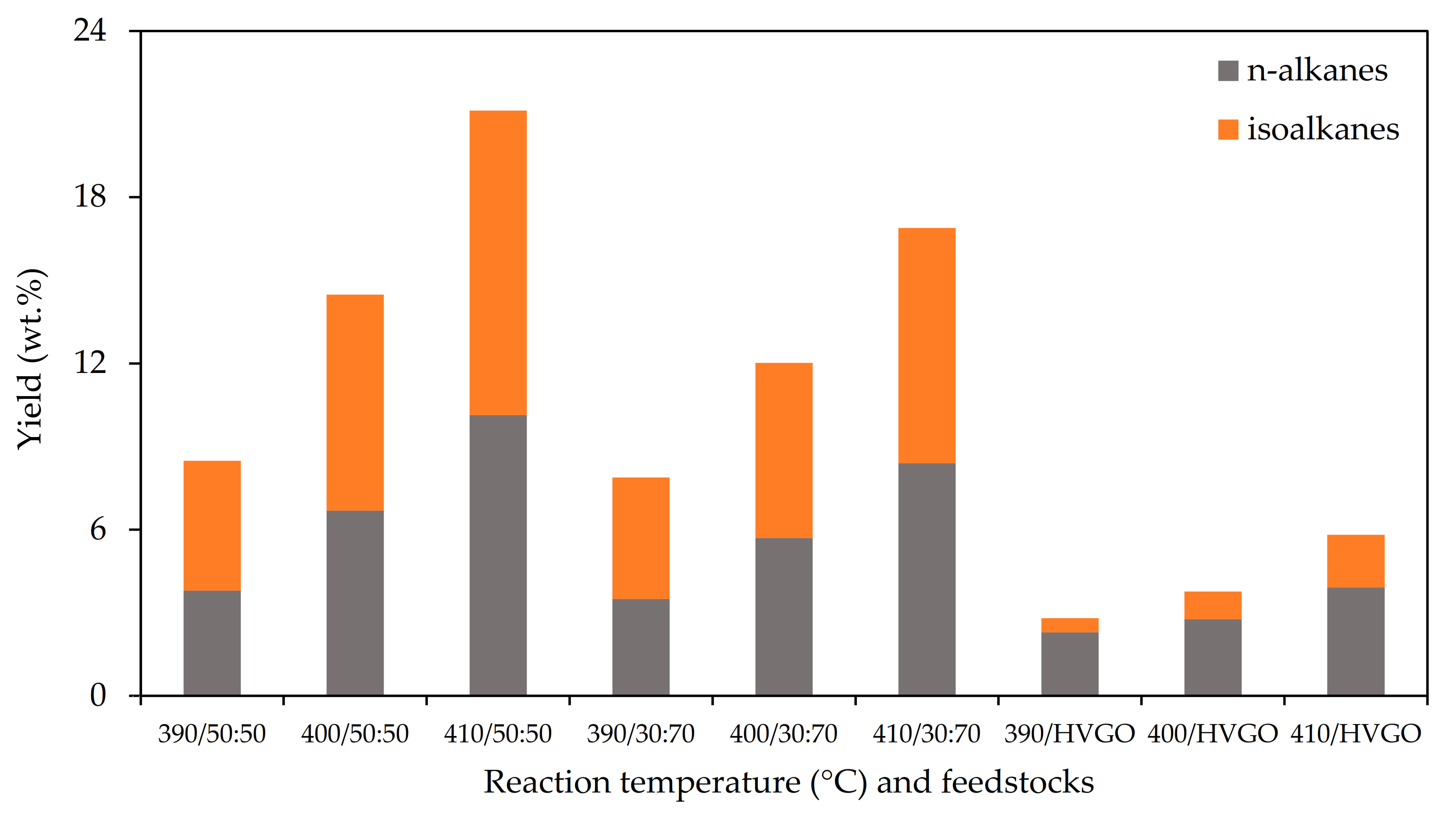
The gaseous products of the hydrocracking were predominantly composed of n-alkanes and isoalkanes. The content of the other hydrocarbon groups was negligible. The increasing reaction temperature of the hydrocracking was reflected by an increase in the yields of both major hydrocarbon groups. The yields also increased with an increasing FT wax content in the feedstock (see Figure 2). This phenomenon was especially observed when the yields from the neat HVGO and feedstock containing 30 wt.% of the FT wax were compared. The increase in the FT wax content from 30 to 50 wt.% was followed only by the less pronounced increase in the gaseous products yields.
While the ratio of n-alkanes and isoalkanes in the gaseous products obtained from the feedstocks containing the FT wax was close to one, the gaseous products from the neat HVGO hydrocracking were mostly composed of n-alkanes. Propane, n-butane and n-pentane were the dominant n-alkanes detected in the gaseous products of the hydrocracking of the FT wax containing feedstocks. The gaseous products obtained from the hydrocracking of the neat HVGO also contained a significant amount of methane and ethane. The branched hydrocarbons were predominantly represented by the C4–C6 isoalkanes in all the gaseous products.
The gaseous products contained a significant portion of C5+ hydrocarbons (22–41 wt.%) which can be attributed to the setup of the samples collection system during the hydrocracking. This loss of highly volatile components via the gaseous products strongly affected the composition and the properties of the naphtha fractions which will be discussed in the following paragraphs.
Gaseous products can be used in the same way as similar petroleum-derived products. They can be used for LPG (liquefied petroleum gas) production or as a feedstock for steam cracking. Although the FT wax used in this work was not produced from a biomass, similar results can be expected with a bio-based feedstock. Such gaseous products can, thus, contribute not only to the production of a renewable LPG fuel with low GHG (greenhouse gas) emissions, but also to the production of renewable (“green”) monomers for the petrochemical industry.

3.3. SIMDIST of Primary Liquid Products

The primary liquid products of the hydrocracking were characterised by the SIMDIST at first. The distillation profiles are shown in Figure 3. The products were composed of hydrocarbons with a wide range of boiling points. The application of the higher reaction temperatures, i.e., 400 and 410 °C, and the addition of the FT wax to the feedstock were reflected by a shift in the distillation curves to lower boiling points. While the products obtained by Xing et al. [19] from the feedstocks with a low FT wax content, especially the one with 25 wt.%, still contained a significant fraction with boiling points higher than the product of the HVGO hydrocracking, all the products of the FT wax containing feedstocks obtained in this study were lighter than the products obtained at the same reaction temperature from the HVGO. It can be associated with the partial conversion of the FT wax discussed above (see Section 3.1). The lightest products were obtained from both the feedstocks containing the FT wax at the reaction temperature of 410 °C. These products were predominantly composed of the gasoline fraction. On the other hand, the products obtained from the HVGO were predominantly composed of middle distillates and a heavier fraction. The distillation profiles of the products obtained from the FT wax containing feedstocks at the reaction temperature of 390 °C were similar to the distillation profile of the product obtained from the HVGO at a temperature of 410 °C.

3.4. Composition and Properties of the Naphtha Fractions

The group-type composition of the naphtha fractions is shown in Table 6. While the naphtha fractions obtained from the hydrocracking of the neat HVGO were dominantly composed of cycloalkanes and aromatics (especially C7–C9), isoalkanes (majorly C6–C10) were the dominant group in the naphtha fractions obtained from the processing of the FT wax containing feedstocks.
It is evident that the increasing reaction temperature led to an increase in the n-alkanes and isoalkanes content. The content of the aromatic hydrocarbons and cycloalkanes decreased with an increasing reaction temperature and an increasing FT wax content in the feedstock. This phenomenon was especially observed from the comparison of the naphtha fractions obtained from the neat HVGO and from the feedstock containing 30 wt.% of the FT wax. The increase in the FT wax content in the feedstock from 30 to 50 wt.% only caused a minor reduction in the aromatics content in the naphtha fractions.
The total aromatics content in all the obtained naphtha fractions ranged from ca. 9 to 30 wt.%. Considering the density of the obtained naphtha fractions (Table 8) and the average density of the aromatics present in these samples (i.e., 870 kg·m−3), all the samples can be considered as complying with the requirement of EN 228 limiting the aromatics content (35 vol.%). Since the highest determined content of benzene was 0.9 wt.%, the same conclusion can also be made for the benzene content, i.e., all the naphtha fractions fulfilled the limit for benzene (max. 1 vol.%) required by the standard EN 228.
The olefins content in all the naphtha fractions was below 0.1 wt.%, so all the samples fulfilled the limit for olefin content (max. 18 vol.%) by a large margin.
While the content of the n-alkanes in the naphtha fractions obtained from the neat HVGO was not affected by the reaction temperature, an increase in their content with an increasing reaction temperature was observed in the naphtha fractions obtained from the feedstocks containing the FT wax.
The content of the i-alkanes was affected by both the reaction temperature and the FT wax content in the feedstock. The increasing reaction temperature and increasing FT wax content in the feedstock were reflected by an increasing i-alkanes content in the naphtha fractions. A significant increase was especially observed in the content of the isopentanes and isohexanes.
The distillation curves of the naphtha fractions are shown in Figure 4. Since the yields of the naphtha fractions of several products were not sufficient to provide the required volume of the sample (i.e., 100 mL) for the standard distillation test according to EN ISO 3405, the standard distillation test was applied only to four samples (Figure 4A). The distillation profiles of the remaining five samples were determined by the simulated distillation only (Figure 4B).
The distillation profiles obtained via the simulated distillation did not show significant differences among the analysed naphtha fractions. On the other hand, the standard distillation test showed a shift in the distillation curves of the naphtha fractions obtained from the feedstocks containing the FT wax at the reaction temperature of 410 °C to lower boiling points. Nevertheless, the naphtha fractions were mostly composed of components having a boiling point above 80 °C.
The summary of the selected parameters of the distillation test and the limits required by the EN 228 standard (class A) for naphtha fractions obtained from the feedstocks containing the FT wax at reaction temperatures of 400 and 410 °C is shown in Table 7. None of the samples met the requirement put on E70. The content of high-volatile compounds was generally quite low in all the naphtha fractions. It can be attributed to the collection system of the liquid products during the hydrocracking in the high and low-pressure separators. The most volatile components of the naphtha fractions left the hydrocracking unit as a part of the gaseous product. It can be supported by the rather large yields of C5–C6 hydrocarbons detected in the gaseous products. While only one sample (410/50:50) met the requirement put on E100, three samples complied with the E150 limit. Only the sample 400/50:50 was slightly below the limit. All the samples met the requirements put on the final boiling point and distillation residue. Generally, the best distillation profile was obtained for the naphtha fraction of the product hydrocracking at 410 °C using the feedstock containing 50 wt.% of the FT wax.
The results of the determination of the other physicochemical properties, i.e., the density and vapour pressure, are shown in Table 8. The increasing reaction temperature and FT wax content in the feedstock were reflected by the decreasing density in the naphtha fractions. It can be mainly attributed to the decreasing content of the cycloalkanes and aromatic hydrocarbons which generally have a higher density when compared to acyclic hydrocarbons. While the naphtha fractions of the products obtained via the hydrocracking of the feedstocks containing the FT wax at 390 and 400 °C met the requirements put on the density, the utilisation of the highest temperature caused a decrease in the density below the limit. The naphtha fractions obtained from the processing of the neat HVGO were on the other edge of the required density range. The fractions of the products 390/HVGO and 400/HVGO were actually above the density limit.
The vapour pressure of the naphtha fraction is dependent on the content of the low-boiling compounds which were lost during the liquid product collection. In spite of the fact that the increasing reaction temperature led to an increase in the vapour pressure of the naphtha fractions obtained from the feedstock containing the FT wax. The vapour pressure of the samples obtained at the lowest reaction temperature, i.e., 390 °C, was significantly below the limit. The increase in the reaction temperature to 400 °C caused a large increase in the naphtha fractions’ vapour pressure. Nevertheless, the vapour pressure of the samples obtained at this reaction temperature was still below the limit. Only the naphtha fractions of the products from the FT wax containing feedstocks obtained at the highest reaction temperature met the requirement of EN 228.
The naphtha fraction yields of the neat HVGO processing at temperatures of 390 and 400 °C were not sufficient enough to measure the vapour pressure. Nevertheless, it can be expected that the result of these samples will be very low.
It can be concluded that both the reaction temperature and the content of the FT wax in the feedstock significantly affected both the chemical composition and physicochemical properties of the naphtha fraction. None of the analysed samples fully met the requirements of the EN 228 standard for automotive gasoline which can be at least partly associated with the loss of the volatile components. This issue could be resolved by using a different setup for the samples’ collection.
Although the naphtha fractions obtained from the feedstocks containing the FT wax contained a rather high portion of isoalkanes, a low knocking resistance (octane number) can be expected. Partly due to the fact that the isoalkanes were majorly represented by mono methyl alkanes and partly due to the high content of n-alkanes and cycloalkanes and the rather low content of aromatic compounds. The direct utilisation of the naphtha fractions as automotive gasoline components would be, therefore, quite limited. Nevertheless, the naphtha fractions could be easily utilised in the petrochemical industry (e.g., steam cracking) or as feedstock for common refinery processes like catalytic reforming and isomerisation.

3.5. Composition and Properties of the Middle Distillates

The results of the group composition of the middle distillates measured by the GC-FID and HPLC analysis are shown in Table 9.
The middle distillates were predominantly composed of saturated hydrocarbons. Their content increased with the increasing content of the FT wax in the feedstock. Cycloalkanes and isoalkanes were the dominant groups of hydrocarbons found in all the middle distillates. While the content of the n-alkanes in the middle distillates obtained from the feedstocks containing the FT wax slightly increased with the increasing reaction temperature, the opposite trend was observed for the middle distillates obtained from the neat HVGO.
The content of aromatic hydrocarbons decreased with the increasing FT wax content in the feedstock. The increasing reaction temperature was reflected by a decrease in the total content of the aromatic hydrocarbons in the middle distillates obtained from the neat HVGO and the feedstock containing 30 wt.% of the FT wax. The minimum content of the aromatic hydrocarbons in the middle distillates obtained from the feedstock containing 50 wt.% was reached at 400 °C. Monocyclic aromatic hydrocarbons were the major group of the aromatic hydrocarbons. The sum of the dicyclic and polycyclic aromatic hydrocarbons in all of the middle distillates did not exceed the limit of EN 590 for diesel fuel, i.e., 8 wt.%. The content of these groups in the middle distillates obtained from the neat HVGO was, however, very close to the limit.
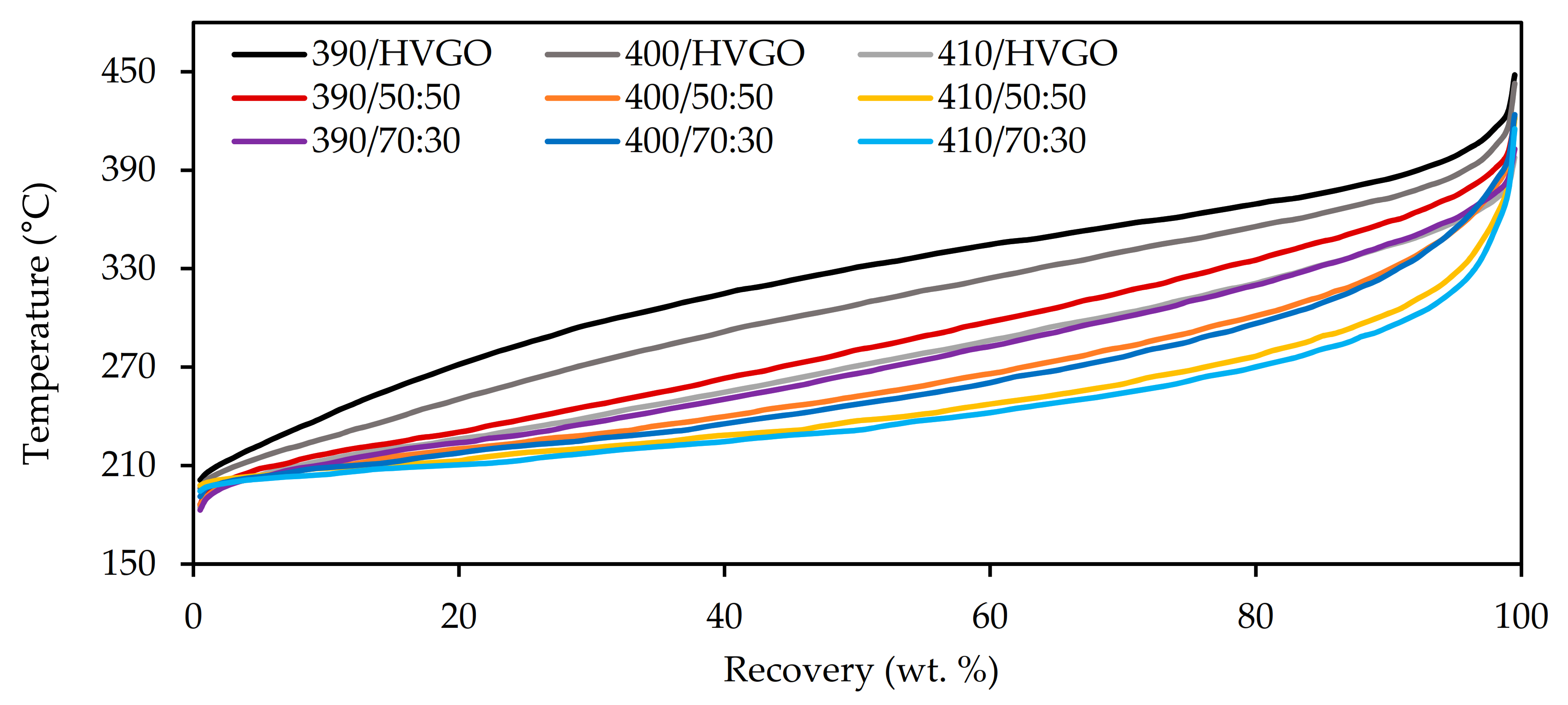
The SIMDIST distillation profiles of all the middle distillates are displayed in Figure 5. Both the increasing reaction temperature and the increasing content in the FT wax in the feedstock were reflected by a shift in the distillation curves to lower boiling points.
The parameters of the distillation test, like R250; R350 and T95, were calculated using the SIMDIST data and the correlation described in the ASTM D2887 standard. The results are displayed in Table 10. As already mentioned above, the increasing reaction temperature led to a decrease in the middle distillates‘ boiling points which was reflected by an increase in both R250 and R350. The same phenomenon also led to a decrease in the temperature at which 95 vol.% (T95) of the sample was recovered. All the middle distillates fractions obtained from the neat HVGO fulfilled the requirements put on the R250 parameter. The addition of the FT wax to the processed feedstock was reflected by the increase in R250. While the middle distillates obtained from the hydrocracking of the FT wax containing the feedstocks at 390 and 400 °C complied with the specification, the R250 parameter of the middle distillates obtained at 410 °C was above the limit. All the analysed middle distillates, except the sample obtained from the neat HVGO at 390 °C, fulfilled the requirement of the EN590 standard put on the R350 parameter. While all the middle distillates obtained from the feedstocks containing the FT wax met the specification in the case of the T95 parameter, only the sample obtained from the neat HVGO at 410 °C was slightly above the maximum value.
The other physicochemical parameters of the middle distillates are summarised in Table 11. The increasing reaction temperature of the hydrocracking was reflected by the decreasing density and kinematic viscosity of the middle distillate fractions. The same phenomenon was also observed for the increasing FT wax content in the feedstocks. The density of the middle distillates obtained from the FT wax containing the feedstocks was below the lower specification limit. On the other hand, the density of the middle distillates obtained from the neat HVGO processing was above the upper limit. The influence of the FT wax content was more significant than the influence of the reaction temperature. The density decrease can be predominantly attributed to the aromatics content decrease discussed above. While the addition of 30 wt.% of the FT wax to the feedstock was reflected by a significant decrease in the middle distillates’ viscosity, the higher content of the FT wax in the feedstock only caused a mild change. The required range of the kinematic viscosity was fulfilled only by the middle distillates obtained from the hydrocracking of the feedstocks containing the FT wax at 390 and 400 °C and of the neat HVGO at 410 °C. The kinematic viscosity of the fractions obtained at 410 °C from the feedstock containing the FT wax was slightly below the limit. On the other hand, the viscosity of the fractions obtained from the neat HVGO at 390 and 400 °C was above the limit.
Although the oxidation stability of the middle distillates was not measured via the standard method (EN 15751), but only via the rapid method based on EN 16091, the middle distillates obtained from the FT wax containing the feedstocks can be considered as very stable. The results, obtained on the basis of correlation between the EN 16091 method (PetroOxy) and the standard EN 15751 method (Rancimat), were significantly higher than the limit value of EN 590.
The cetane index of the middle distillates was calculated using density and the data obtained via the simulated distillation correlated to the standard distillation test. All the samples, except the middle distillate obtained from the hydrocracking of the neat HVGO at 410 °C, complied with the requirement of the EN 590 standard put on the cetane index. Nevertheless, the cetane index of the non-complying sample mentioned above was only slightly below the lower specification limit. The increasing FT wax content in the feedstock was reflected by an increase in the cetane index. The cetane indexes of the middle distillates obtained from the FT wax containing the feedstocks were, thus, significantly above the minimum value required by EN 590.
Although the middle distillate fractions obtained from the hydrocracking of the neat HVGO and the HVGO containing the FT wax could not be utilised as diesel fuel in a pure form, they can be used at least as a blending component. Due to the low aromatics content and high of iso- and cycloalkanes content, the middle distillates from the FT wax containing the feedstocks could also be used as low-aromatic industrial solvents. The distillation cut of 180–275 °C could be, additionally, used for the production of high-quality jet fuel.

4. Conclusions

The hydrocracking of the vacuum distillate containing the Fischer–Tropsch (FT) wax was carried out in a fixed-bed reactor at reaction temperatures of 390, 400 and 410 °C and a pressure of 8 MPa. The neat vacuum distillate and mixtures of 30 and 50 wt.% of the FT wax with the vacuum distillate were used as the feedstocks. The obtained primary liquid products were separated by distillation into a naphtha fraction and middle distillates which were characterised using various analytical methods.
Both the content of the FT wax in the hydrocracked feedstock and higher reaction temperature had a positive effect on the total conversion of the fraction boiling above 400 °C to lighter fractions. The full conversion of the feedstocks containing the FT wax was achieved at the reaction temperatures of 400 and 410 °C. The products obtained at these conditions were mainly composed of a naphtha fraction (57.0–58.9 wt.%), while the rest was formed by gaseous products (12.3–30.0 wt.%) and middle distillates (8.7–24.8 wt.%).
The yield of the gaseous products increased with both the increasing reaction temperature and the FT content wax in the feedstock. While the ratio of n-alkanes and isoalkanes in the gaseous products obtained from the feedstocks containing the FT wax was close to 1, the gaseous products of the neat HVGO hydrocracking were mostly composed of n-alkanes.
The higher FT wax content in the feedstock and reaction temperature affected the chemical composition and physicochemical properties of the naphtha fraction. While the content of i-alkanes and n-alkanes increased with an increasing FT wax content in the feedstock, the content of cycloalkanes and aromatics decreased. Although the direct utilisation of the naphtha fractions as an automotive gasoline would be rather limited, it is still possible to use them either as a gasoline blending component or as a feedstock for common refinery processes like isomerisation and reforming to improve their composition and properties. The naphtha fractions from the FT wax containing feedstocks could be utilised in the petrochemical industry as well.
Neither of the obtained middle distillates complied with the particular quality standard, i.e., EN 590. While the direct utilisation as an automotive diesel fuel would also be limited, the middle distillate fractions can be used as a blending component in the diesel fuel production. Due to the low content of aromatics and the high content of iso- and cycloalkanes, the middle distillates obtained from the FT wax containing the feedstocks could also be used, for example, as low-aromatic industrial solvents. Moreover, the distillation cut of 180–275 °C could be used for the production of high-quality jet fuel.

Author Contributions

Conceptualization, P.S. (Petr Straka); methodology, P.S. (Petr Straka); validation, O.P. and D.V.; formal analysis, O.P., P.S. (Petr Straka), P.Š. (Pavel Šimáček); investigation, O.P.; resources, O.P.; data curation, O.P.; writing—original draft preparation, O.P. and D.V.; writing—review and editing, O.P., D.V., P.S. (Petr Straka), A.V., J.J.; visualization, D.V.; supervision, P.S. (Petr Straka) and P.Š. (Pavel Šimáček); project administration, O.P. All authors have read and agreed to the published version of the manuscript.

Funding

This work is related to the project COMSYN that received funding from the European Union’s Horizon 2020 research and innovation programme under grant agreement No. 727476. The work was also funded by the Ministry of Education, Youth and Sports of the Czech Republic from the National Sustainability Programme (NPU I LO1613, MSMT-43760/2015) and specific university research (MSMT No 21-SVV/2018). The APC was funded by University of Chemistry and Technology, Prague.

Conflicts of Interest

The authors declare no conflict of interest.

Abbreviations

The following abbreviations are used in this manuscript:
DVPEDry vapour pressure equivalent
E70, E100, E150Evaporated at 70, 100 and 150 °C
ENEuropean Standard
FCCFluid catalytic cracking
FIDFlame ionisation detector
FTFischer–Tropsch
FTS Fischer–Tropsch synthesis
GCGas chromatography
GHGGreenhouse gas
GTLGas-to-liquid
HPLCHigh Performance Liquid Chromatography
HVGOHeavy vacuum gas oil
ISOInternational Organization for Standardization
LPGLiquified petroleum gases
R250, R350 Recovery at 250 and 350 °C
SIMDISTSimulated distillation
T10, T50, T90, T9510, 50, 90 and 95 vol.% recovered at
WHSVWeight hour space velocity
XTLX-to-liquid

References

  1. Oil 2018: Analysis and forecasts to 2023. International Energy Agency [online]. 2018. Available online: https://www.iea.org/reports/oil-2018 (accessed on 4 March 2020).
  2. Valdivia, M.; Galan, J.L.; Laffarga, J.; Ramos, J.-L. Biofuels 2020: Biorefineries based on lignocellulosic materials. Microb. Biotechnol. 2016, 9, 585–594. [Google Scholar] [CrossRef] [PubMed]
  3. Chen, M.; Smith, P.M.; Wolcott, M.P. US biofuels industry: A critical review of the opportunities and challenges. Bioprod. Bus. 2016, 1, 42–59. [Google Scholar]
  4. Moriarty, P.; Yan, X.; Wang, S. Liquid biofuels: Not a long-term transport solution. Energy Procedia 2019, 158, 3265–3270. [Google Scholar] [CrossRef]
  5. Bae, C.; Kim, J. Alternative fuels for internal combustion engines. Proc. Combust. Inst. 2017, 36, 3389–3413. [Google Scholar] [CrossRef]
  6. King, D.L.; De Klerk, A. Overview of feed-to-liquid (XTL) conversion. In Synthetic Liquids Production and Refining; ACS Publication: Washington, DC, USA, 2011; pp. 1–24. [Google Scholar]
  7. Leckel, D. Hydrocracking of Iron-Catalyzed Fischer−Tropsch Waxes. Energy Fuels 2005, 19, 1795–1803. [Google Scholar] [CrossRef]
  8. Pleyer, O.; Šimáček, P. Advanced biofuels produced by Fischer-Tropsch synthesis. In Proceedings of the 2nd International Conference on Environmental Technology and Innovations, Prague, Czech Republic, 21–22 November 2018. [Google Scholar]
  9. Pleyer, O.; Straka, P.; Vrtiška, D.; Hájek, J.; Černý, R. Hydrocracking of Fischer-Tropsch Wax. Paliva 2020, 2, 26–33. [Google Scholar] [CrossRef]
  10. Kim, Y.H.; Jun, K.-W.; Joo, H.; Han, C.; Song, I.K. A simulation study on gas-to-liquid (natural gas to Fischer–Tropsch synthetic fuel) process optimization. Chem. Eng. J. 2009, 155, 427–432. [Google Scholar] [CrossRef]
  11. Hoehn, R.; Thakkar, V.; Yuh, E. Hydroprocessing for Clean Energy: Design, Operation, and Optimization; John Wiley & Sons: Hoboken, NJ, USA, 2017. [Google Scholar]
  12. Dancuart, L.; De Haan, R.; De Klerk, A. Processing of primary Fischer-Tropsch products. In Studies in Surface Science and Catalysis; Elsevier: Amsterdam, The Netherlands, 2004; pp. 482–532. [Google Scholar]
  13. Bouchy, C.; Hastoy, G.; Guillon, E.; Martens, J.A. Fischer-Tropsch waxes upgrading via hydrocracking and selective hydroisomerization. Oil Gas Sci. Technol. Rev. IFP 2009, 64, 91–112. [Google Scholar] [CrossRef] [Green Version]
  14. Robinson, P.R.; Dolbear, G.E. Hydrotreating and hydrocracking: Fundamentals. In Practical Advances in Petroleum Processing; Springer: Berlin/Heidelberg, Germany, 2006; pp. 177–218. [Google Scholar]
  15. Rao, T.M.; Dupain, X.; Makkee, M. Fluid catalytic cracking: Processing opportunities for Fischer–Tropsch waxes and vegetable oils to produce transportation fuels and light olefins. Microporous Mesoporous Mater. 2012, 164, 148–163. [Google Scholar] [CrossRef]
  16. Lappas, A.A.; Iatridis, D.K.; Vasalos, I.A. Production of Liquid Biofuels in a Fluid Catalytic Cracking Pilot-Plant Unit Using Waxes Produced from a Biomass-to-Liquid (BTL) Process. Ind. Eng. Chem. Res. 2011, 50, 531–538. [Google Scholar] [CrossRef]
  17. Kubička, D.; Černý, R. Upgrading of Fischer–Tropsch Waxes by Fluid Catalytic Cracking. Ind. Eng. Chem. Res. 2011, 51, 8849–8857. [Google Scholar] [CrossRef]
  18. Šimáček, P.; Kubička, D.; Pospíšil, M.; Rubáš, V.; Hora, L.; Šebor, G. Fischer–Tropsch product as a co-feed for refinery hydrocracking unit. Fuel 2013, 105, 432–439. [Google Scholar] [CrossRef]
  19. Xing, T.; De Crisci, A.G.; Chen, J. Hydrocracking of Fischer-Tropsch wax and its mixtures with heavy vacuum gas oil. Can. J. Chem. Eng. 2018, 97, 1515–1524. [Google Scholar] [CrossRef]
  20. European Committee. EN 228+A1. Automotive Fuels—Unleaded Petrol—Requirements and Test Methods; European Committee for Standardization: Brussels, Belgium, 2018. [Google Scholar]
  21. European Committee. EN 590+A1. Automotive Fuels—Diesel—Requirements and Test Methods; European Committee for Standardization: Brussels, Belgium, 2018. [Google Scholar]
Figure 1. The distillation profiles (SIMDIST) of the HVGO, Fischer–Tropsch (FT) wax and blends.
Energies 13 05497 g001
Figure 2. Yields and composition of the gaseous products of the hydrocracking.
Energies 13 05497 g002
Figure 3. The distillation profiles (SIMDIST) of the primary liquid products.
Energies 13 05497 g003
Figure 4. The distillation profiles of the naphtha fractions obtained via the standard test EN ISO 3405 (A) and the simulated distillation (B).
Energies 13 05497 g004
Figure 5. The distillation profiles of the middle distillates.
Energies 13 05497 g005
Table 1. The physicochemical parameters of the Sarawax SX70 a and heavy vacuum gas oil (HVGO).
ParameterUnitValueTesting Methods
Sarawax SX 70 HVGO
Density at 15 °Ckg·m−3842912ASTM D1217
Kinematic viscosity at 100 °Cmm2·s−16.54.7ASTM D445
Simulated distillation
T10°C438356ISO 3924
T50°C488434ISO 3924
T90°C535517ISO 3924
Sulfur contentmg·kg−1<122,400ISO 20846
Carbonisation residuewt.%0.0050.011ISO 10370
Appearance-white granulesbrown viscous liquidVisual
a commercial specification for Sarawax SX70 (Shell, Malaysia).
Table 2. The reaction conditions of the hydrocracking.
ParameterUnitValue
Reaction temperature°C390, 400, 410
PressureMPa8
H2/feed flowrate ratiom3·m−31000
Feedstock flowrateg·h−145
WHSV ah−11.0
a Weight hour space velocity.
Table 3. The basic parameters used for the characterisation of the naphtha fraction and the EN 228 specification for gasoline.
ParameterUnitLimits (EN 228)Testing Methods
Min.Max.
Density at 15 °Ckg·m−3720.0775.0EN ISO 12185
Vapour pressure EN 13016-1
class A (summer)kPa45.060.0
class D (winter)kPa60.090.0
Distillation test EN ISO 3405
E70 class Avol.%20.048.0
class Dvol.%22.050.0
E100vol.%46.071.0
E150vol.%75.0-
Final boiling point (FBP)°C-210
Distillation residuevol.%-2.0
Aromaticsvol.%-35.0EN ISO 22854
Benzenevol.%-1.0EN ISO 22854
Olefinsvol.%-18.0EN ISO 22854
Table 4. The basic parameters used for the characterisation of the middle distillate and the EN 590 specification for diesel fuel.
ParameterUnitLimits (EN 590)Testing Methods
Min.Max.
Kinematic viscosity at 40 °Cmm2·s−12.04.50EN ISO 3104
Density at 15 °Ckg·m−3820.0845.0EN ISO 12185
Polycyclic aromatic hydrocarbonswt.%-8.0EN 12916
Cetane index-46.0-EN ISO 4264
Oxidation stability min60 a-EN 16091
a The limit value is based on the correlation between the EN 16091 (PetroOxy) method and the standard EN 15751 (Rancimat) method.
Table 5. The mass balance of the hydrocracking and the yields of the obtained products.
Product
(Temp°C/HVGO:FT Wax)
Yields of Hydrocracking Products (wt.%)Liquid Products Fractional Composition (wt.%)Conversion
(%)
ProductsLosses<200 °C200–400 °C>400 °CLosses
GaseousLiquid
390/50:508.888.92.333.428.124.92.570.7
400/50:5014.784.11.258.523.7-1.9100
410/50:5030.067.82.257.08.7-2.1100
390/70:308.390.11.630.229.128.42.464.6
400/70:3012.385.52.258.924.8-1.8100
410/70:3026.370.63.158.810.5-1.3100
390/HVGO3.194.52.44.729.459.41.016.0
400/HVGO4.593.71.89.234.848.11.632.0
410/HVGO5.891.92.322.237.630.81.356.4
Table 6. The composition of the naphtha fractions.
SampleContent (wt.%)
n-AlkanesIsoalkanesAromaticsCycloalkanes
390/50:5010.538.715.128.7
400/50:5014.450.210.319.2
410/50:5016.353.39.217.7
390/70:308.437.717.729.7
400/70:3012.246.412.622.2
410/70:3014.047.910.921.0
390/HVGO12.518.230.432.7
400/HVGO12.019.028.733.4
410/HVGO12.225.723.831.4
Table 7. The selected results of the distillation test of the naphtha fractions and the limits of EN 228 (class A).
SampleE70
(vol.%.)
E100
(vol.%.)
E150
(vol.%.)
Final Boiling Point (°C)Residue (vol.%.)
EN 22820–4846–71min. 75max. 210max. 2
400/50:5010.732.273.5195.31.0
410/50:5018.547.585.5197.10.9
400/70:3012.433.275.5195.21.0
410/70:3015.440.581.7191.81.0
Table 8. The density and vapour pressure of the naphtha fractions.
SampleDensity at 15 °C (kg·m−3)Vapor Pressure (kPa)
EN 228720–77545–60 a
390/50:507558.1
400/50:5072239.3
410/50:5070949.8
390/70:307599.2
400/70:3072941.8
410/70:3071947.0
390/HVGO787 - b
400/HVGO784 - b
410/HVGO76924.6
a for gasoline class A (summer type), b not measured due to lack of sample.
Table 9. The group composition of the middle distillates.
SampleContent (wt.%)
Mono AromaticsDi
Aromatics
Poly
Aromatics
n-AlkanesCycloalkanes +
Isoalkanes
390/50:509.81.10.38.380.5
400/50:506.60.80.88.783.1
410/50:508.21.21.211.977.6
390/70:3017.32.60.36.872.9
400/70:3012.51.61.27.677.1
410/70:3012.11.41.49.176.0
390/HVGO37.06.50.87.748.0
400/HVGO33.56.60.96.852.3
410/HVGO26.65.50.66.660.8
Table 10. The results of the selected distillation parameters of the middle distillates.
SampleR250 (vol.%.)R350 (vol.%.)T95 (°C)
EN 590Max. 65Min. 85Max. 360
390/50:5026.794.8350
400/50:5050.3>95332
410/50:5068.6>95307
390/70:3036.6>95337
400/70:3054.4>95333
410/70:3073.7>95297
390/HVGO3.679.9372
400/HVGO10.989.6361
410/HVGO33.0>95335
Table 11. The other physicochemical parameters of the middle distillates.
SampleDensity at 15 °CKin. Viscosity at 40 °COxidation StabilityCetane Index
(kg·m−3)(mm2·s−1)(Hours)-
EN 590820–8452–4,5min. 1 amin 46
390/50:508033.0025.972.2
400/50:507892.4033.571.5
410/50:507861.9528.190.7
390/70:308182.8424.560.7
400/70:308022.4723.163.3
410/70:307931.8325.562.9
390/HVGO8766.7218.148.6
400/HVGO8725.5413.946.5
410/HVGO8573.2116.545.7
a The limit value based on the correlation between the method EN 16091 (PetroOxy) and standard method EN 15751 (Rancimat).
Publisher’s Note: MDPI stays neutral with regard to jurisdictional claims in published maps and institutional affiliations.

