Low Emissions Resulting from Combustion of Forest Biomass in a Small Scale Heating Device

 ,
,  ,
,  , ,
, ,
Abstract
1. Introduction
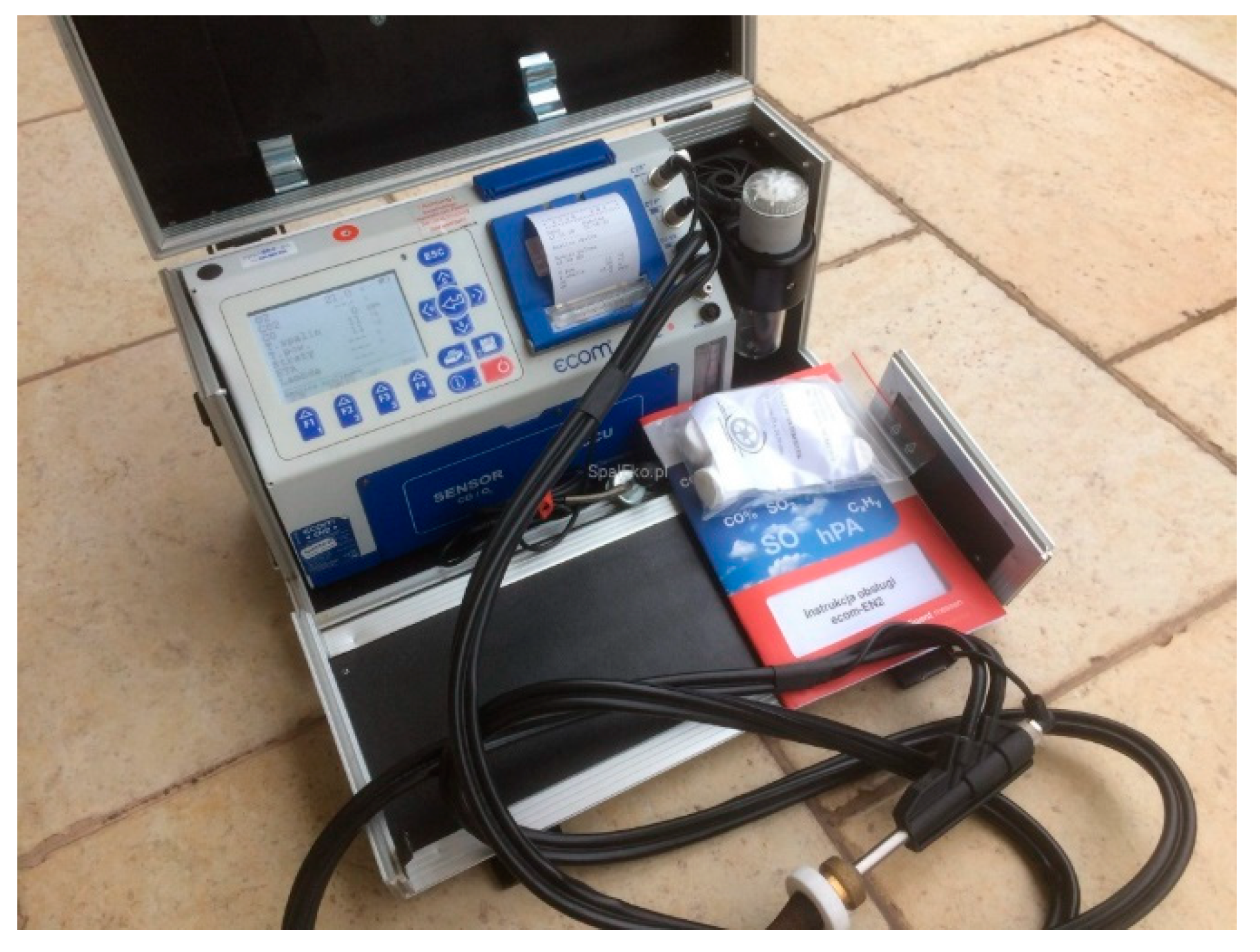
2. Tests and Measurements of Examples of the Devices Used
3. Materials and Methods
Materials
4. Results and Discussion
4.1. Burning the Wood-Derived Fuels
4.2. Calculation of Exhaust Gas Characteristics
4.3. Summary of the Characteristics of a Low-Emission Heating Device
4.4. Discussion of Results
5. Conclusions
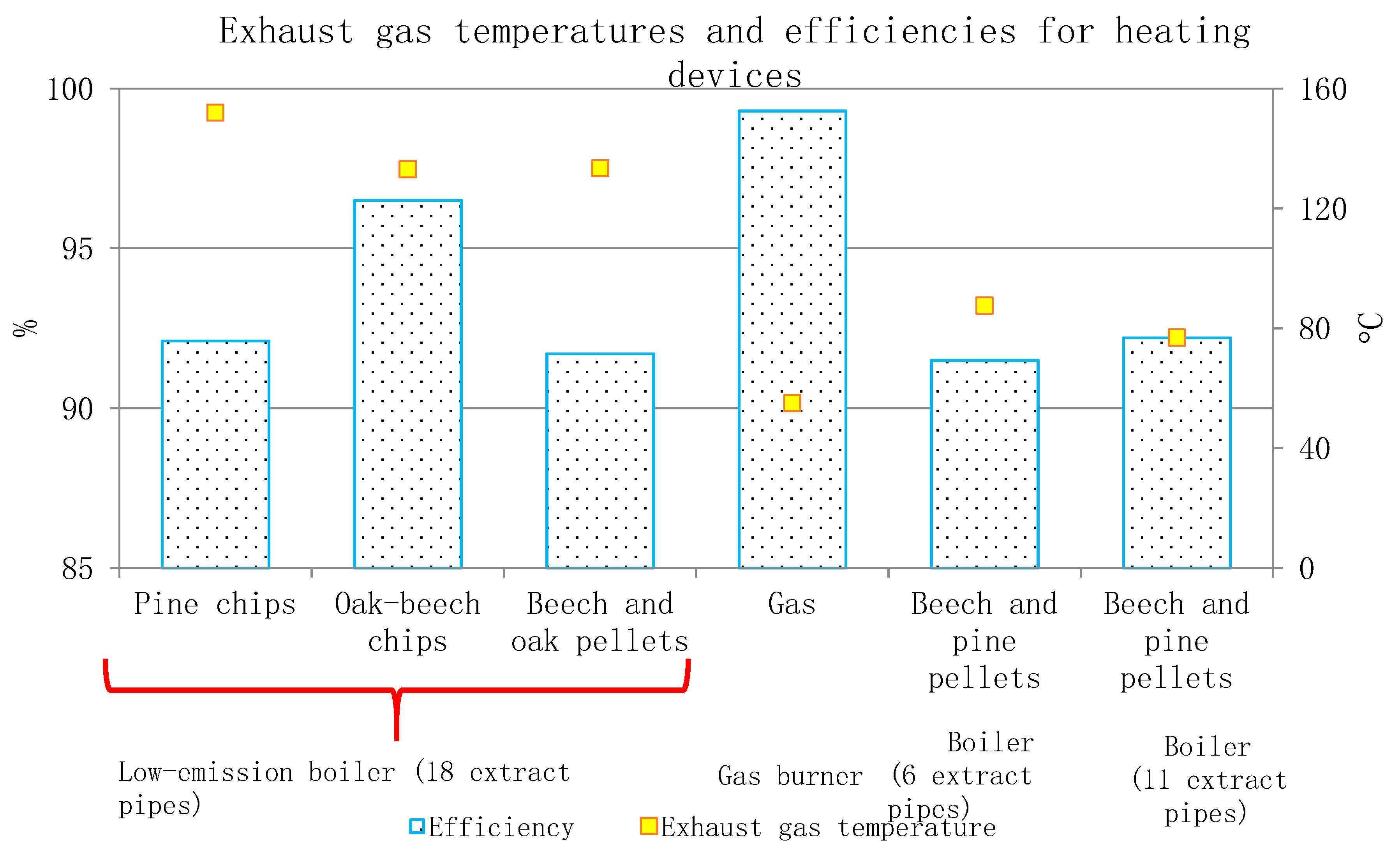
- The thermodynamic efficiency of the proposed technical solution exceeds 92% and exceeds or at least equals the solutions available on the market;
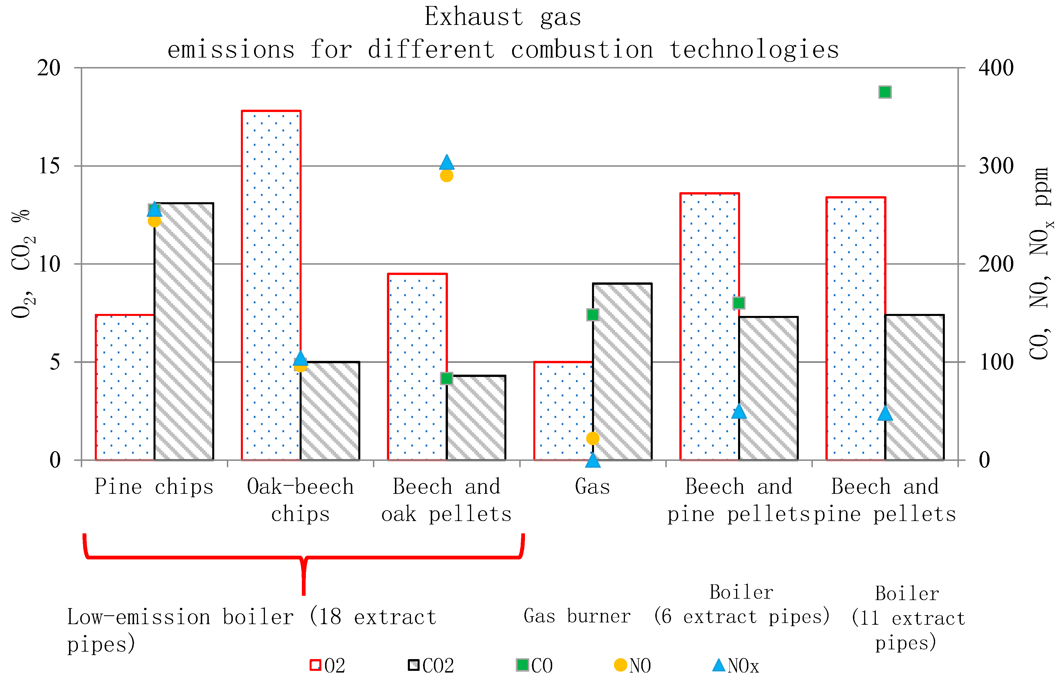
- in the case of combustion of beech and oak pellets, the emission of CO2, CO, O2 in the proposed heating device was many times lower than the emission from devices available on the market;
- the emission of exhaust gases during the combustion of pine chips and beech and oak pellets is many times lower than the emission from lignite, which is important, especially in the context of countries where the energy mix is based on coal.
Author Contributions
Funding
Conflicts of Interest
References
- Friedlingstein, P.; Jones, M.W.; O’Sullivan, M.; Andrew, R.M.; Hauck, J.; Peters, G.P.; Peters, W.; Pongratz, J.; Sitch, S.; Le Quéré, C.; et al. Global Carbon Budget 2019. Earth Syst. Sci. Data 2019, 11, 1783–1838. [Google Scholar] [CrossRef]
- Guo, H.; Hu, J.; Yu, S.; Sun, H.; Chen, Y. Computing of the contribution rate of scientific and technological progress to economic growth in Chinese regions. Expert Syst. Appl. 2012, 39, 8514–8521. [Google Scholar] [CrossRef]
- Dunaj, P.; Berczyński, S.; Miądlicki, K.; Irska, I.; Niesterowicz, B. Increasing Damping of Thin-Walled Structures Using Additively Manufactured Vibration Eliminators. Materials 2020, 13, 2125. [Google Scholar] [CrossRef] [PubMed]
- Kowal, J.; Kot, A. Active vibration reduction system with energy regeneration. Arch. Control. Sci. 2007, 17, 343–352. [Google Scholar]
- Zhu, W.; Zhang, Z.; Li, X.; Feng, W.; Li, J. Assessing the effects of technological progress on energy efficiency in the construction industry: A case of China. J. Clean. Prod. 2019, 238, 117908. [Google Scholar] [CrossRef]
- Wang, H.; Wei, W. Coordinating technological progress and environmental regulation in CO2 mitigation: The optimal levels for OECD countries & emerging economies. Energy Econ. 2020, 87, 104510. [Google Scholar]
- Tucki, K.; Orynycz, O.; Mitoraj-Wojtanek, M. Perspectives for Mitigation of CO2 Emission due to Development of Electromobility in Several Countries. Energies 2020, 13, 4127. [Google Scholar] [CrossRef]
- Lin, S.; Lin, R.; Sun, J.; Wang, F.; Wu, W. Dynamically evaluating technological innovation efficiency of high-tech industry in China: Provincial, regional and industrial perspective. Socio Econ. Plan. Sci. 2020, 100939. in press. [Google Scholar] [CrossRef]
- Wei, Z.; Han, B.; Han, L.; Shi, Y. Factor substitution, diversified sources on biased technological progress and decomposition of energy intensity in China’s high-tech industry. J. Clean. Prod. 2019, 231, 87–97. [Google Scholar] [CrossRef]
- Jiang, Y.; Asante, D.; Zhang, J.; Cao, M. The effects of environmental factors on low-carbon innovation strategy: A study of the executive environmental leadership in China. J. Clean. Prod. 2020, 266, 121998. [Google Scholar] [CrossRef]
- Barzegar, M.; Rashidinejad, M.; MollahassaniPour, M.; Bakhshai, A.; Farahmand, H. A techno-economic assessment of energy efficiency in energy management of a micro grid considering green-virtual resources. Sustain. Cities Soc. 2020, 61, 102169. [Google Scholar] [CrossRef]
- Matuszek, J. Trends and directions of production engineering development. Prod. Innow. Product. Innov. 2005, 1, 2–7. [Google Scholar]
- Martins, F.; Felgueiras, C.; Smitková, M. Fossil fuel energy consumption in European countries. Energy Procedia 2018, 153, 107–111. [Google Scholar] [CrossRef]
- Gökgöz, F.; Güvercin, M.T. Energy security and renewable energy efficiency in EU. Renew. Sustain. Energy Rev. 2018, 96, 226–239. [Google Scholar] [CrossRef]
- Vanhala, P.; Bergström, I.; Haaspuro, T.; Kortelainen, P.; Holmberg, M.; Forsius, M. Boreal forests can have a remarkable role in reducing greenhouse gas emissions locally: Land use-related and anthropogenic greenhouse gas emissions and sinks at the municipal level. Sci. Total Environ. 2016, 557–558, 51–57. [Google Scholar] [CrossRef]
- Lapuerta, M.; Hernandez, J.J.; Rodrıguez-Fernandez, J.; Barba, J.; Ramos, A.; Fernandez-Rodrıguez, D. Emission benefits from the use of n-butanol blends in a Euro 6 diesel engine. Int. J. Engine Res. 2017, 19, 1099–1112. [Google Scholar] [CrossRef]
- Fesanghary, M.; Asadi, S.; Geem, Z.W. Design of low-emission and energy-efficient residential buildings using a multi-objective optimization algorithm. Build. Environ. 2012, 49, 245–250. [Google Scholar] [CrossRef]
- Cang, Y.; Yang, L.; Luo, Z.; Zhang, N. Prediction of embodied carbon emissions from residential buildings with different structural forms. Sustain. Cities Soc. 2020, 54, 101946. [Google Scholar] [CrossRef]
- Ma, M.; Ma, X.; Cai, W.; Cai, W. Low carbon roadmap of residential building sector in China: Historical mitigation and prospective peak. Appl. Energy 2020, 273, 115247. [Google Scholar] [CrossRef]
- What is Smog and Low Emission? How to Contribute to Reducing Air Pollution? Available online: https://muratordom.pl/instalacje/ogrzewanie-domu/czym-jest-smog-i-niska-emisja-jak-przyczynic-sie-do-zmniejszenia-zanieczyszczenia-powietrza-aa-DgcH-7Pmb-4WuS.html (accessed on 31 July 2020).
- Guide to Low Carbon Residential Buildings—Retrofit. Available online: https://apo.org.au/sites/default/files/resource-files/2019-05/apo-nid235556.pdf (accessed on 31 July 2020).
- Low Carbon Buildings. Available online: https://www.climatebonds.net/standard/buildings (accessed on 31 July 2020).
- Luo, T.; Tan, Y.; Langston, C.; Xue, X. Mapping the knowledge roadmap of low carbon building: A scientometric analysis. Energy Build. 2019, 194, 163–176. [Google Scholar] [CrossRef]
- Charles, A.; Maref, W.; Ouellet-Plamondon, C.M. Case study of the upgrade of an existing office building for low energy consumption and low carbon emissions. Energy Build. 2019, 183, 151–160. [Google Scholar] [CrossRef]
- The Role of District Heating in the Fight Against Low Emissions. Available online: https://powietrze.malopolska.pl/wp-content/uploads/2017/03/9-Mirowski-A-No_2_ICEB-_AGH_03.03.17.pdf (accessed on 31 July 2020).
- Counteracting Low Emissions in Dense Residential Areas. Available online: http://home.agh.edu.pl/~szk/files/docs/niska_emisja.pdf (accessed on 31 July 2020).
- Mirowski, T.; Orzechowska, M. The use of biomass fuels in individual heating in areas threatened by low emission. Polityka Energetyczna Energy Policy J. 2015, 18, 75–88. [Google Scholar]
- Herbuś, B. Low emissions—High risk. Energetyka Cieplna Zawodowa 2017, 2, 24–28. [Google Scholar]
- Tartakovsky, D.; Kordova–Biezuner, L.; Berlin, E.; Broday, D.M. Air quality impacts of the low emission zone policy in Haifa. Atmos. Environ. 2020, 232, 117472. [Google Scholar] [CrossRef]
- Climate Change 2013: The Physical Science Basis. Contribution of Working Group I to the Fifth Assessment Report of the Intergovernmental Panel on Climate Change. Available online: http://www.climatechange2013.org/report/full-report/ (accessed on 30 September 2020).
- An IPCC Special Report on the Impacts of Global Warming of 1.5 °C above Pre-Industrial Levels and Related Global Greenhouse Gas Emission Pathways, in the Context of Strengthening the Global Response to the Threat of Climate Change, Sustainable Development, and Efforts to Eradicate Poverty. Available online: https://www.ipcc.ch/site/assets/uploads/sites/2/2019/06/SR15_Full_Report_High_Res.pdf (accessed on 30 September 2020).
- Jiang, W.; Boltze, M.; Groer, S.; Scheuvens, D. Impacts of low emission zones in Germany on air pollution levels. Transp. Res. Procedia 2017, 25, 3370–3382. [Google Scholar] [CrossRef]
- Holman, C.; Harrison, R.; Querol, X. Review of the efficacy of low emission zones to improve urban air quality in European cities. Atmos. Environ. 2015, 111, 161–169. [Google Scholar] [CrossRef]
- Efficient and Environmentally Friendly Heat Sources—Reducing Low Emissions. Available online: https://fewe.pl/wp-content/uploads/2018/08/Poradnik-niska-emisja-FEWE_Kubica.pdf (accessed on 31 July 2020).
- Viessmann. Verification of Heating Equipment and System Heat in Terms of Air Emissions—Author’s Certificates and Building Signs “PreQurs”. Available online: https://www.viessmann.pl/content/dam/vi-brands/PL/Inne/Cieplo_z_zimna/no-smog.pdf/_jcr_content/renditions/original./no-smog.pdf (accessed on 31 July 2020).
- Mirowski, T. Utilization of Biomass for Energy Purpose Versus Reduction of Emission of Air Pollutants from Municipal and Households Sector. Rocz. Ochr. Środowiska 2016, 18, 466–477. [Google Scholar]
- Kryzia, D.; Pepłowska, M. The Impact of Measures Aimed at Reducing Low-Stack Emission in Poland and on Energy Efficiency and the Household Emission of Pollutants. Polityka Energetyczna 2019, 22, 121–132. [Google Scholar] [CrossRef]
- Panteliadis, P.; Strak, M.; Hoek, G.; Weijers, E.; Van der Zee, S.; Dijkema, M. Implementation of a low emission zone and evaluation of effects on air quality by long-term monitoring. Atmos. Environ. 2014, 86, 113–119. [Google Scholar] [CrossRef]
- Ferreira, F.; Gomes, P.; Tente, H.; Carvalho, A.C.; Pereira, P.; Monjardino, J. Air quality improvements following implementation of Lisbon’s Low Emission Zone. Atmos. Environ. 2015, 122, 373–381. [Google Scholar] [CrossRef]
- Stala-Szlugaj, K. Hard coal combustion in the municipal and housing sector—Influence on “Low Emission”. Rocz. Ochr. Środowiska 2011, 13, 1877–1889. [Google Scholar]
- Kosowski, K.; Tucki, K.; Piwowarski, M.; Stepien, R.; Orynycz, O.; Wlodarski, W. Thermodynamic Cycle Concepts for High-Efficiency Power Plants. Part B: Prosumer and Distributed Power Industry. Sustainability 2019, 11, 2647. [Google Scholar] [CrossRef]
- Szulecki, K. Securitization and state encroachment on the energy sector: Politics of exception in Poland’s energy governance. Energy Policy 2020, 136, 111066. [Google Scholar] [CrossRef]
- Brauers, H.; Oei, P.Y. The political economy of coal in Poland: Drivers and barriers for a shift away from fossil fuels. Energy Policy 2020, 144, 111621. [Google Scholar] [CrossRef]
- Sustainable Cities. Living in A Healthy Atmosphere. Available online: http://obserwatorium.miasta.pl/wp-content/uploads/2016/10/Raport-Zr%C3%B3wnowa%C5%BCone-miasta.pdf (accessed on 30 September 2020).
- Climate for Poland, Poland for the Climate. Available online: https://cop24.gov.pl/fileadmin/user_upload/files/1._Klimat-dla-Polski-Polska-dla-Klimatu_PL.pdf (accessed on 30 September 2020).
- Expert Study on the Introduction of Restrictions on the Use of Solid Fuels in the Area of Kraków. Available online: https://powietrze.malopolska.pl/wp-content/uploads/2017/02/Ekspertyza_paliwa_Krakow_2010.pdf (accessed on 30 September 2020).
- Solid Fuels in the PONE Programmes in the Light of the So-Called “Soft”. The Anti-Smog Act. Available online: http://wszystkooemisjach.pl/260/paliwa-stale-w-programach-pone-w-swietle-tzw-ustawy-antysmogowej (accessed on 31 July 2020).
- Best Practices for Low Emission Elimination. Available online: http://portpc.pl/najlepsze-praktyki-likwidacji-niskiej-emisji/ (accessed on 31 July 2020).
- Emission Standards for Domestic Boilers—Ecodesign and PN-EN 303-5:2012. Available online: https://czysteogrzewanie.pl/podstawy/norma-pn-en-303-5-2012/ (accessed on 31 July 2020).
- Report. Polish Coal 2. 0. Smokeless Fuels vs. Smog. Available online: http://jagiellonski.pl/files/other/1536001531.pdf (accessed on 31 July 2020).
- Proszak-Miąsik, D.; Rabczak, S. Methods for Reducing Low Emissions from Heating Devices in Single- Family Housing. Available online: https://www.e3s-conferences.org/articles/e3sconf/pdf/2018/20/e3sconf_infraeko2018_00069.pdf (accessed on 31 July 2020).
- Guide to Low-Emission Boiler and Combustion Equipment Selection. Available online: https://www.energy.gov/sites/prod/files/2014/05/f15/guide_low_emission.pdf (accessed on 31 July 2020).
- Opinion of the European Economic and Social Committee on the ‘Communication from the Commission to the European Parliament, the Council, the European Economic and Social Committee and the Committee of the Regions—A Clean Air Programme for Europe’ COM(2013) 918 Final. Available online: https://eur-lex.europa.eu/legal-content/EN/TXT/?uri=CELEX:52014AE0637 (accessed on 30 September 2020).
- EU Approves New Rules for Member States to Drastically Cut Air Pollution. Available online: https://ec.europa.eu/commission/presscorner/detail/en/MEMO_16_4372 (accessed on 30 September 2020).
- Use of Coal in the Heating of Buildings. Available online: http://xn--oszczdnybudynek-d9b.pl/zastosowanie-wegla-w-ogrzewaniu-budynkow/ (accessed on 29 September 2020).
- The Government is Preparing Subsidies for the Energy Modernisation of Multi-Family Buildings. Available online: https://gramwzielone.pl/ (accessed on 30 September 2020).
- Wang, D.; Liu, L.; Yuan, Y.; Yang, H.; Zhou, Y.; Duan, R. Design and key heating power parameters of a newly-developed household biomass briquette heating boiler. Renew. Energy 2020, 147, 1371–1379. [Google Scholar] [CrossRef]
- Judt, W.; Ciupek, B.; Urbaniak, R. Numerical study of a heat transfer process in a low power heating boiler equipped with afterburning chamber. Energy 2020, 196, 117093. [Google Scholar] [CrossRef]
- Tucki, K.; Orynycz, O.; Wasiak, A.; Swic, A.; Wichlacz, J. The Impact of Fuel Type on the Output Parameters of a New Biofuel Burner. Energies 2019, 12, 1383. [Google Scholar] [CrossRef]
- Zhang, X.; Li, K.; Zhang, C.; Wang, A. Performance analysis of biomass gasification coupled with a coal-fired boiler system at various loads. Waste Manag. 2020, 105, 84–91. [Google Scholar] [CrossRef]
- Design of heating systems. Available online: http://www.instsani.pl/220/projektowanie-instalacji-grzewczych (accessed on 31 July 2020).
- Zhu, M.; Zhou, J.; Su, S.; Xu, J.; Li, A.; Chen, L.; Wang, Y.; Hu, S.; Jiang, L.; Xiang, J. Study on supercritical CO2 coal-fired boiler based on improved genetic algorithm. Energy Convers. Manag. 2020, 221, 113163. [Google Scholar] [CrossRef]
- Guide Design of Solid Biomass Heating Systems. Available online: http://bape.com.pl/pliki/publikacjePDF/2/Projektowanie%20systemow%20grzewczych%20opalanych%20biomasa%20stala_FOREST_poradnik.pdf (accessed on 31 July 2020).
- Ericsson, K.; Werner, S. The introduction and expansion of biomass use in Swedish district heating systems. Biomass Bioenergy 2016, 94, 57–65. [Google Scholar] [CrossRef]
- Bunn, D.W.; Redondo-Martin, J.; Munoz-Hernandez, J.I.; Diaz-Cachinero, P. Analysis of coal conversion to biomass as a transitional technology. Renew. Energy 2019, 132, 752–760. [Google Scholar] [CrossRef]
- Royo, J.; Canalis, P.; Quintana, D.; Diaz-Ramirez, M.; Sin, A.; Rezeau, A. Experimental study on the ash behaviour in combustion of pelletized residual agricultural biomass. Fuel 2019, 239, 991–1000. [Google Scholar] [CrossRef]
- Kažimírová, V.; Opáth, R. Biomass combustion emissions. Res. Agric. Eng. 2016, 62, 61–65. [Google Scholar] [CrossRef]
- Neuenschwander, P.; Good, J.; Nussbaumer, T. Combustion efficiency in biomass furnaces with flue gas condensation. In Proceedings of the Biomass for Energy and Industry, 10th European Conference and Technology Exhibition, Wurzburg, Germany, 8–11 June 1998; Available online: https://www.bfe.admin.ch/php/modules/enet/streamfile.php?file=000000000374.pdf (accessed on 17 February 2019).
- Guo, F.; Zhong, Z. Optimization of the co-combustion of coal and composite biomass pellets. J. Clean. Prod. 2018, 185, 399–407. [Google Scholar] [CrossRef]
- Stam, A.F.; Brem, G. Fouling in coal-fired boilers: Biomass co-firing, full conversion and use of additives—A thermodynamic approach. Fuel 2019, 239, 1274–1283. [Google Scholar] [CrossRef]
- Xu, G.; Li, M.; Lu, P. Experimental investigation on flow properties of different biomass and torrefied biomass powders. Biomass Bioenergy 2019, 122, 63–75. [Google Scholar] [CrossRef]
- Xingru, L.; Lei, J.; Yu, B.; Yang, Y.; Shuiqiao, L.; Xi, C.; Jing, X.; Yusi, L.; Yingfeng, W.; Xueqing, G.; et al. Wintertime aerosol chemistry in Beijing during haze period: Significant contribution from secondary formation and biomass burning emission. Atmos. Res. 2019, 218, 25–33. [Google Scholar]
- Růžičková, J.; Kucbel, M.; Raclavská, H.; Švédová, B.; Raclavský, K.; Juchelková, D. Comparison of organic compounds in char and soot from the combustion of biomass in boilers of various emission classes. J. Environ. Manag. 2019, 236, 769–783. [Google Scholar] [CrossRef]
- Chaoyang, Z.; Yongqiang, W.; Qiye, J.; Qijuan, C.; Yuegui, Z. Mechanism analysis on the pulverized coal combustion flame stability NOx emission in a swirl burner with deep air staging. J. Energy Inst. 2019, 92, 298–310. [Google Scholar]
- Biomass for Heat. Available online: https://www.wbdg.org/resources/biomass-heat (accessed on 31 July 2020).
- Biomass Boilers: Measurement of In-Situ Performance. Available online: https://www.gov.uk/government/publications/biomass-boilers-measurement-of-in-situ-performance (accessed on 31 July 2020).
- Heating and cooling with biomass—Summary report—D6.1. Available online: https://ec.europa.eu/energy/intelligent/projects/sites/iee-projects/files/projects/documents/eubionet_iii_hc_with_biomass_en.pdf (accessed on 31 July 2020).
- Placek, V.; Oswald, C.; Hrdlicka, J. Optimal Combustion Conditions for a Small-scale Biomass Boiler. Acta Polytech. 2012, 52, 89–92. [Google Scholar]
- Kang, S.B.; Kim, J.J.; Choi, K.S.; Sim, B.S.; Oh, H.Y. Development of a test facility to evaluate performance of a domestic wood pellet boiler. Renew. Energy 2013, 54, 2–7. [Google Scholar] [CrossRef]
- Mack, R.; Kuptz, D.; Schön, C.; Hartmann, H. Combustion behavior and slagging tendencies of kaolin additivated agricultural pellets and of wood-straw pellet blends in a small-scale boiler. Biomass Bioenergy 2019, 125, 50–62. [Google Scholar] [CrossRef]
- Juszczak, M.; Cichy, W.; Pałaszyńska, K. Usefulness assessment of automatic air flow control system with oxygen sensor in a 20 kW boiler with periodic wood pellet supply. Drew. Pract. Nauk. Doniesienia Komun. 2016, 59, 111–130. [Google Scholar]
- PN-EN 303-5:2012. Heating Boilers. Part 5. Heating Boilers for Solid Fuels, Hand and Automatically Stocked, Nominal Heat Output of Up to 500 kW. Terminology, Requirements, Testing and Marking. Available online: https://instalreporter.pl/ogolna/kotly-z-klasa-czyli-jak-narodzila-sie-klasa-5/ (accessed on 31 July 2020).
- Paraschiv, L.S.; Serban, A.; Paraschiv, S. Calculation of combustion air required for burning solid fuels (coal / biomass / solid waste) and analysis of flue gas composition. Energy Rep. 2020, 6, 36–45. [Google Scholar] [CrossRef]
- Shi, Y.; Liu, Q.; Shao, Y.; Zhong, W. Energy and exergy analysis of oxy-fuel combustion based on circulating fluidized bed power plant firing coal, lignite and biomass. Fuel 2020, 269, 117424. [Google Scholar] [CrossRef]
- Smolarz, A. Diagnostyka Procesów Spalania Paliw Gazowych, Pyłu Węglowego Oraz Mieszaniny Pyłu Węglowego i Biomasy z Wykorzystaniem Metod Optycznych. Available online: http://bc.pollub.pl/dlibra/publication/5156/edition/4054?language=pl (accessed on 30 September 2020).
- Caposciutti, G.; Barontini, F.; Galletti, C.; Antonelli, M.; Tognotti, L.; Desideri, U. Woodchip size effect on combustion temperatures and volatiles in a small-scale fixed bed biomass boiler. Renew. Energy 2020, 151, 161–174. [Google Scholar] [CrossRef]
- Description of the Functioning of the System for Biomass Combustion. Available online: https://instalreporter.pl/ogolna/analiza-procesu-spalania-w-kotlach-kondensacyjnych/ (accessed on 31 July 2020).
- Liu, J.; Luo, X.; Yao, S.; Li, Q.; Wang, W. Influence of flue gas recirculation on the performance of incinerator-waste heat boiler and NOx emission in a 500 t/d waste-to-energy plant. Waste Manag. 2020, 105, 450–456. [Google Scholar] [CrossRef]
- Tu, Y.; Zhou, A.; Xu, M.; Yang, W.; Siah, K.B.; Subbaiah, P. NOX reduction in a 40 t/h biomass fired grate boiler using internal flue gas recirculation technology. Appl. Energy 2018, 220, 962–973. [Google Scholar] [CrossRef]
- Jafari, H.; Yang, W.; Ryu, C. Evaluation of a distributed combustion concept using 1-D modeling for pressurized oxy-combustion system with low flue gas recirculation. Fuel 2020, 263, 116723. [Google Scholar] [CrossRef]
- Zhang, G.; Xu, W.; Wang, X.; Yang, Y. Analysis and optimization of a coal-fired power plant under a proposed flue gas recirculation mode. Energy Convers. Manag. 2015, 102, 161–168. [Google Scholar] [CrossRef]
- Gómez, M.A.; Martín, R.; Chapela, S.; Porteiro, J. Steady CFD combustion modeling for biomass boilers: An application to the study of the exhaust gas recirculation performance. Energy Convers. Manag. 2019, 179, 91–103. [Google Scholar] [CrossRef]
- Roiha, I.; Kaikko, J.; Jaanu, K.; Vakkilainen, E. Analysis of high flue gas recirculation for small energy conversion systems. Appl. Therm. Eng. 2014, 63, 218–226. [Google Scholar] [CrossRef]
- Zhang, G.; Xu, W.; Wang, X.; Yang, Y. Sensitivity Analysis and Optimization of a Coal-fired Power Plant in Different Modes of Flue Gas Recirculation. Energy Procedia 2014, 61, 2114–2117. [Google Scholar] [CrossRef]
- Sungur, B.; Topaloglu, B. An experimental investigation of the effect of smoke tube configuration on the performance and emission characteristics of pellet-fuelled boilers. Renew. Energy 2019, 143, 121–129. [Google Scholar] [CrossRef]
- Kurzyński, J.; Mańskowski, S.; Rubik, M. Zbiór Zadań z Techniki Cieplnej, 1st ed.; Wydawnictwo Politechniki Warszawskiej: Warszawa, Polska, 1973; pp. 14–212. [Google Scholar]
- Sadowski, A.; Żółtowski, B.; Kałaczyński, T.; Liss, M. Internal Combustion Engine Energy Balance Modelling in Terms and Provisions of Efficiency. Stud. Proc. Pol. Assoc. Knowl. Manag. 2016, 79, 214–222. [Google Scholar]
- Ronewicz, K.; Turzyński, T.; Kardaś, D. Modelling of flow and heat exchange processes in a biomass grate boiler. Arch. Spalania 2012, 12, 101–108. [Google Scholar]
- Taler, J. Procesy Cieplne i Przepływowe w Dużych Kotłach Energetycznych, 1st ed.; Wydawnictwo Naukowe PWN: Warszawa, Polska, 2011; pp. 160–360. [Google Scholar]
- Pronobis, M. Modernizacja Kotłów Energetycznych, 1st ed.; Wydawnictwo Naukowe PWN: Warszawa, Polska, 2017; pp. 25–132. [Google Scholar]
- Nowak, W. Energetyczne Wykorzystanie Biomasy. Available online: http://www.plan-rozwoju.pcz.pl/wyklady/ener_srod/rozdzial3.pdf (accessed on 30 September 2020).
- Nowak, W.; Wesołowska, M. Uwarunkowania Techniczne Spalania Biomasy w Kotłach Energetycznych. Available online: https://www.ibles.pl/documents/10180/105133/biomasa-15-nowak.pdf (accessed on 30 September 2020).
- Hackschnitzelkessel mit Automatischer Beschickung. Available online: http://energieberatung.ibs-hlk.de/planhack_kessel.htm (accessed on 30 September 2020).
- Die Hackschnitzelheizung. Available online: https://heizung.de/holzheizung/hackschnitzelheizung/ (accessed on 30 September 2020).
- Boilers for Biomass Combustion—Summary of Manufacturers’ Offer. Available online: https://www.instalacjebudowlane.pl/6341-23-40-kotly-do-spalania-biomasy--zestawienie-oferty-producentow.html?isbn=6341-23-40-kotly-do-spalania-biomasy--zestawienie&idkat=oferty&nr=producentow (accessed on 30 September 2020).
- Boilers Fired by Chips, Shavings, Briquettes and Pellets. Available online: http://www.rencraft.eu/wp-content/uploads/2016/06/KOT%C5%81Y-ZAUTOMATYZOWANE-HDG-25-80-KW_2015.pdf (accessed on 30 September 2020).
- Biomass Boiler. Available online: https://www.ceneo.pl/;szukaj-kocio%c5%82+na+biomas%c4%99 (accessed on 30 September 2020).
- Wasiak, A. Modeling Energetic Efficiency of Biofuels Production. Green Energy and Technology, 1st ed.; Springer Nature Switzerland: Cham, Switzerland, 2018; pp. 29–47. ISBN 978-3-319-98430-8. [Google Scholar] [CrossRef]


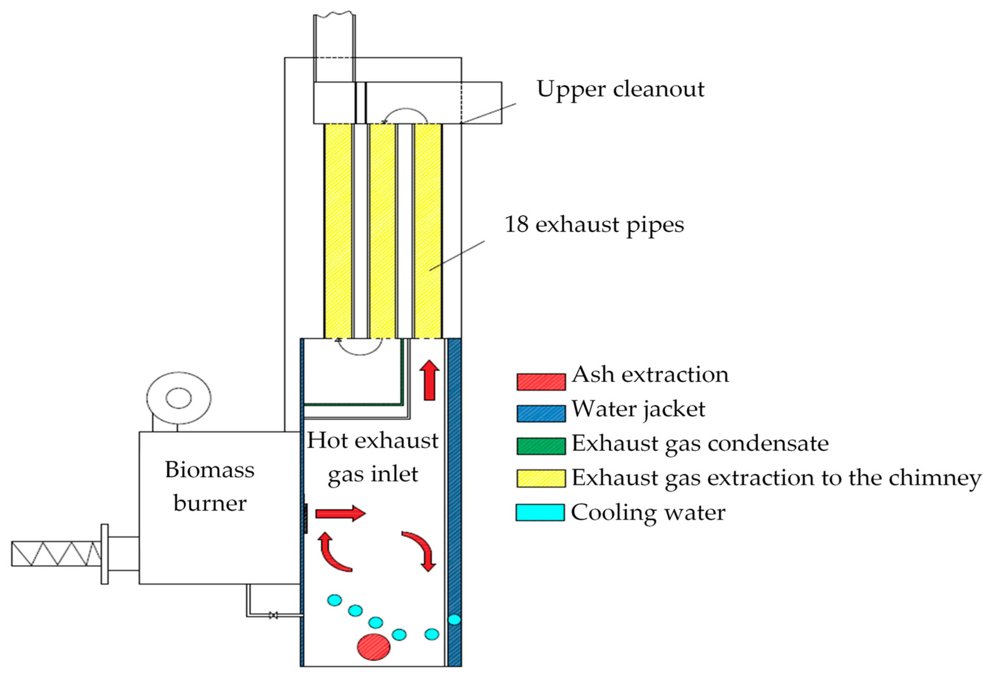
| Parameter | Dimension (mm) |
|---|---|
| Boiler height | 2350 |
| Cleaning hatch height | 160 |
| Height to cleaning hatch | 2110 |
| Combustion chamber height | 1310 |
| Dimensions of exhaust pipes | Ø82 × 6.3 × 820 |
| Combustion chamber wall thickness | 8 |
| Ash extract | Ø101 |
| Boiler width | 662 |
| Width of exhaust pipes spacing | 446 |
| Parameter | Description | Unit |
|---|---|---|
| m | share of the element in the fuel | |
| N | atomic mass of element | |
| molecular mass of oxygen | ||
| minimum oxygen demand (molar) | ||
| excess air for solid fuels | [-] | |
| minimum air demand | ||
| molar fraction of hydrogen in the fuel | ||
| molar degree of air humidity | ||
| molar fraction of water vapor in the fuel | ||
| actual air demand | ||
| molar fraction of the exhaust gas component | ||
| M | molecular weight | |
| mass fraction of compound x in the exhaust gas | ||
| relative amount of wet exhaust | ||
| mass fraction of ash in the fuel | ||
| fuel stream | ||
| exhaust mass flow | ||
| share of compound x in exhaust gas composition | ||
| w | dust lift indicator | |
| η | dust extraction efficiency | % |
| K | flammable content in dust | % |
| C | mass fraction of carbon in the fuel | |
| H | mass fraction of hydrogen in the fuel | |
| S | mass fraction of sulfur in the fuel | |
| O | mass fraction of oxygen in the fuel |
| Parameter | Pine Chips | Oak–Beech Chips | Beech-Oak Pellets |
|---|---|---|---|
| Transient moisture 1 | 27% | 24% | 3.23% |
| Analytical moisture 2 | 9.11% | 6.78% | 2.80% |
| Ash | 0.85% | 0.70% | 0.24% |
| Volatile matter | 82.87% | 84.77% | |
| Fixed carbon | 7.17% | 7.75% | |
| Sulphur | 0.33% | 0.29% | 0.01% |
| Carbon | 32.31% | 31.60% | 50.86% |
| Hydrogen | 5.10% | 7.70% | 6.36% |
| Nitrogen | 0.13% | 0.18% | 39.53% |
| Chlorine | <0.1% | <0.1% | 0.2% |
| Oxygen | 45% | 45% | |
| Ash softening temperature | 1200 °C | 1200 °C | |
| Calorific value | 10 MJ/kg | 16 MJ/kg | |
| Lower calorific valuein relation to the weight | 3.7 kWh/kg | 5.92 kWh/kg | |
| Lower calorific value in relation to the volume | 750 kWh/m3 | 1200 kWh/m3 |
| Exhaust Component | Pine Woodchips | Oak–Beech Chips | Beech and Oak Pellets | Unit |
|---|---|---|---|---|
| O2 1 | 7.4 | 17.8 | 9.5 | % |
| CO | 255 | 97.33 | 83 | ppm |
| NO | 244 | 96.20 | 290 | ppm |
| NOx | 256 | 104 | 304 | ppm |
| CO2 1 | 13.1 | 5.0 | 4.3 | % |
| η 2 | 92.1 | 96.5 | 97.7 | % |
| Losses | 7.9 | 5.04 | 5.1 | % |
| λ | 1.54 | 1.60 | 1.83 | |
| Exhaust gas temperature | 152 | 133.1 | 133.4 |
| Parameter | Pine Chips | Beech and Oak Pellet | Unit |
|---|---|---|---|
| Minimum oxygen demand for combustion by mass | 0.743 | 1.46 | |
| Minimum oxygen demand for combustion (molar) | 0.00232 | 0.0457 | |
| Minimum air demand for combustion | 0.111 | 0.217 | |
| Actual air demand for combustion | 0.177 | 0.348 | |
| Total wet exhaust quantity | 4.318 | 8.212 | |
| Stream of the fuel part without ash—ballast | 2.97 | 2.98 | |
| Wet exhaust gas mass flow | 12.852 | 24.56 | |
| CO2 emission | 2.995 | 5.57 | |
| SO2 emission | 0.0197 | 0.0006 | |
| N2 emission | 7.313 | 14.39 | |
| O2 emission | 0.134 | 2.613 | |
| H2O emission | 2.39 | 1.98 | |
| Dust emission | 0.000191 | 0.000054 |
| Quantity | Low-Emission Boiler—18 Extract Pipes | Low-Emission Boiler—18 Extract Pipes | Low-Emission Boiler—18 Extract Pipes | Gas Burner | Boiler—6 Extract Pipes | Boiler—11 Extract Pipes | Unit |
|---|---|---|---|---|---|---|---|
| Type of fuel | Pine chips | Oak–beech chips | Beech and oak pellets | Gas | Beech and pine pellets | Beech and pine pellets | |
| O2 | 7.4 | 17.8 | 9.5 | 5 | 13.6 | 13.4 | % |
| CO | 255 | 97.33 | 83 | 148 | 160 | 375 | ppm |
| NO | 244 | 96.20 | 290 | 22 | - | - | ppm |
| NOx | 256 | 104 | 304 | - | 50 | 48 | ppm |
| CO2 | 13.1 | 5 | 4.3 | 9 | 7.3 | 7.4 | % |
| η | 92.1 | 96.5 | 97.7 | 99.3 | 91.5 | 92.2 | % |
| Loses | 7.9 | 5.04 | 5.1 | - | - | - | % |
| λ | 1.54 | 1.60 | 1.83 | 1.3 | - | - | - |
| Exhaust gas temperature | 152 | 133.1 | 133.4 | 55.1 | 87.6 | 76.9 | °C |
| Exhaust Component | Emission—Pine Chips | Emission—Beech and Oak Pellets | Emission—Lignite | Unit |
|---|---|---|---|---|
| CO2 | 2.995 | 5.57 | 103.63 | |
| SO2 | 0.0197 | 0.0006 | 1.62 | |
| N2 | 7.313 | 14.39 | 447.7 | |
| O2 | 0.134 | 2.613 | 50.93 | |
| H2O | 2.39 | 1.98 | 44.13 | |
| Dust | 0.000191 | 0.000054 | 0.0663 |
Publisher’s Note: MDPI stays neutral with regard to jurisdictional claims in published maps and institutional affiliations. |
© 2020 by the authors. Licensee MDPI, Basel, Switzerland. This article is an open access article distributed under the terms and conditions of the Creative Commons Attribution (CC BY) license (http://creativecommons.org/licenses/by/4.0/).
Share and Cite
Tucki, K.; Orynycz, O.; Wasiak, A.; Świć, A.; Mieszkalski, L.; Wichłacz, J. Low Emissions Resulting from Combustion of Forest Biomass in a Small Scale Heating Device. Energies 2020, 13, 5495. https://doi.org/10.3390/en13205495
Tucki K, Orynycz O, Wasiak A, Świć A, Mieszkalski L, Wichłacz J. Low Emissions Resulting from Combustion of Forest Biomass in a Small Scale Heating Device. Energies. 2020; 13(20):5495. https://doi.org/10.3390/en13205495
Chicago/Turabian StyleTucki, Karol, Olga Orynycz, Andrzej Wasiak, Antoni Świć, Leszek Mieszkalski, and Joanna Wichłacz. 2020. "Low Emissions Resulting from Combustion of Forest Biomass in a Small Scale Heating Device" Energies 13, no. 20: 5495. https://doi.org/10.3390/en13205495
APA StyleTucki, K., Orynycz, O., Wasiak, A., Świć, A., Mieszkalski, L., & Wichłacz, J. (2020). Low Emissions Resulting from Combustion of Forest Biomass in a Small Scale Heating Device. Energies, 13(20), 5495. https://doi.org/10.3390/en13205495