Abstract
This paper aims to conduct a parametric study for five gas turbine cycles (namely, simple, heat exchanged, free turbine and simple cycle, evaporative, and humidified) using a CO2-argon-steam-oxyfuel (CARSOXY) mixture as a working fluid to identify their optimal working conditions with respect to cycle efficiency and specific work output. The performance of the five cycles using CARSOXY is estimated for wet and dry compression, and a cycle is suggested for each range of working conditions. The results of this paper are based on MATLAB codes, which have been developed to conduct the cycle analysis for CARSOXY gas turbines, assuming a stoichiometric condition with an equivalence ratio of 1.0. Analyses are based on the higher heating value (HHV) of methane as fuel. This paper also identifies domains of operating conditions for each cycle, where the efficiency of CARSOXY cycles can be increased by up to 12% compared to air-driven cycles. The CARSOXY heat exchanged cycle has the highest efficiency among the other CARSOXY cycles in the compressor pressure ratio domain of 2–3 and 6–10, whereas, at 3–6, the humidified cycle has the highest efficiency. The evaporative cycle has intermediate efficiency values, while the simple cycle and the free turbine-simple cycle have the lowest efficiencies amongst the five cycles. Additionally, a 10% increase in the cycle efficiency can be theoretically achieved by using the newly suggested CARSOXY blend that has the molar fractions of 47% argon, 10% carbon dioxide, 10% H2O, and 33% oxyfuel at low compressor inlet temperatures, thus theoretically enabling the use of carbon capture technologies.
1. Introduction
The subject of using alternative working fluids in gas turbines has attracted global interests due to its potential for increasing efficiency and reducing the carbon footprint. The literature has reported several attempts to replace conventional working fluids with other alternatives. To name a few, pure oxygen has been studied to replace air in gas turbines, helium has been utilized as a cooling agent in nuclear reactors, and a mixture of ammonia and steam has been utilized to replace pure steam in Kalina cycles, amongst many others in the literature that could potentially be integrated to raise cycle efficiencies to support the use of carbon capture and storage (CCS) systems. Although CCS has been on the sight of researchers, industries, and governments for over a decade, extremely limited implementations exist worldwide. In principle, these implementations’ main barriers are the costs incurred in these CCS technologies accompanied by the efficiency penalties that make the overall system unaffordable when compared to regular cycles.
The growing interest of CCS is a consequence of today’s strict carbon emission regulations. For example, carbon emissions levels need to be reduced by 80% compared to 1990 levels within thirty years by the UK government to comply with the Climate Change Act [1], which is based on an international commitment from such countries. However, it must be explicitly highlighted that CCS always penalizes cycle efficiency. A typical gas-fired plant without CCS has an efficiency of 55.6%. This efficiency drops from 47.4% to 41.5% based on the CCS technology that is applied to the overall sequestration of emissions, thus decreasing efficiency by at least 8% with its incurred costs [2]. Over 20 technically feasible CO2 injection activities in the power generation industry have been proposed around the globe to implement CCS [2]. However, it is due to economics and feasibility that most projects never materialize.
Therefore, while inert gases’ chemical reactivity is negligible, their enhanced thermodynamic characteristics (i.e., high heat capacities) contribute to increasing power outputs and thus increase cycle efficiency. For example, nuclear reactors have relied heavily on utilizing helium as a “safe” cooling agent for the last four decades because of its low chemical reactivity and radioactivity [3]. Aside from nuclear reactors, helium could be utilized as a working fluid in gas turbines without the necessity of performing major medications on combustion chambers of existing gas turbines, thus following the conventional design practice [4]. However, the same cannot be said about the compressor of a gas turbine; blades require major modification to suppress end-wall boundary layer growth, which accompanies the usage of helium and affects the compressor mechanical efficiency [5]. The literature [6] has reported efforts to tradeoff between efficiency and mechanical requirements by introducing inert gasses such as neon and helium to the working fluid mixture. For instance, a blend composed of both inert gases (i.e., helium and neon) has been exploited to reach an optimum expansion ratio. However, such a blend has a negligible effect on enhancing cycle efficiency. Therefore, the necessity of introducing other gases remains in order to maintain high efficiency while reducing maintenance. Most importantly, introducing a blend as an alternative working fluid must include CO2 in its composition to consider the CO2 circulation resulting from the deployment of carbon-capturing systems.
Oxyfuel combustion is a trending technique that is mainly coupled with CO2 circulation. Oxyfuel combustion is based on using high oxygen concentrations as the primary oxidant instead of air (i.e., with 21 vol% oxygen content) [6] while using CO2 as a diluent to overcome turbine overheating, which accompanies the usage of high oxygen content. The natural products of oxyfuel combustion are only carbon dioxide and steam, and the product mass and volume are 75% lower in comparison to conventional fuel/air combustion. Therefore, carbons produced from oxyfuel combustion are captured and circulated back using lower energy than those produced from conventional fuel/air combustion [7].
However, circulating carbons back to a gas turbine drops the turbine inlet temperature and leads to the necessity of using bigger compressors, thus increasing the gas turbine’s size. Moreover, the attempts of modifying compressors and other parts of the gas turbine to cope with the new requirements of using circulating carbons to the system (i.e., adjusting turbine and compressor pressure ratios) delay the deployment of this technique in an industrial level [8,9]. Inert gases could be injected into the system to maintain the high heat capacity of the working fluid to overcome this obstacle. Amongst the options of inert gases, argon has a high potential to be used due to its availability in the atmosphere and the existence of its fully developed extracting approach (i.e., air separation units (ASU)). Injecting argon to a blend of carbon dioxide and oxygen retains turbine inlet temperature to its average level while allowing more heat to be transferred by increasing the working fluid’s overall heat capacity. Therefore, the costs of major modifications are avoided. Moreover, increasing the working fluid’s overall heat capacity shall increase the cycle efficiency, which compensates for energy losses, which are due to the deployment of a CCS unit. However, argon with oxyfuel combustion costs are much higher if only Ar-O2-CO2 blends are employed as working fluids. To avoid this high cost while ensuring high efficiency and power outputs, steam could be injected into the Ar-O2-CO2 blend by various advanced humidified systems. The topic of steam injection has been well covered in the literature to study multiple parameters in a broad range of applications, such as those reported by reference [10]. Injecting steam increases power outputs by increasing mass flow rates, thus increasing cycle efficiency.
Coupling those humidification systems to heat exchanging units is usually referred to as complex cycles [11]. These cycles have the potential of increasing efficiency and reducing emissions by recovering approximately 60% of heat losses [12]. Heat recovery methods include heat exchanging and recuperation techniques, such as gas-to-gas recuperation. This method is mainly used for low-pressure ratios. For higher pressure ratios, steam injection is a more proper approach [13]. On top of that, thermal efficiencies and output power are increased compared to similar simple gas turbines. However, water is needed, and extensive post-treatment is required. This is the major limitation of these humidified cycles [14,15]. A more straightforward technique is evaporative cycles, which have higher power output but lower efficiency than a similar steam injection cycle. Humidification is also used for other purposes, such as cooling and overcoming sizing limitations of the compressor, referred to as wet compression [16,17].
Using a mixture of carbon dioxide, argon, and steam as a working fluid is referred to as CARSOXY [18]. Theoretical evidence has been provided illustrating enhancements in the gas turbine performance using CARSOXY, supported by heat exchangers to recover heat and facilitate humidification and evaporation techniques [18]. High techno-economic advantages could be obtained under the proper cycle arrangements. Most importantly, CARSOXY mixtures have proven to increase efficiency while reducing CO2 emissions by other CCS techniques, which are considered imperative requirements for future fossil-fueled gas turbines [19,20]. However, the CO2 composition in the CARSOXY blends shall be carefully chosen and controlled to be within the acceptable levels to avoid the accumulation of CO2 deposits, which could cause blockage in cooling channels in the turbine blades [21,22].
In addition to the potential increase of cycle efficiency, the elegance of utilizing the proposed blend of CARSOXY (i.e., carbon dioxide, argon, and steam) as a working fluid also appears in facilitating an opportunity to integrate magnetohydrodynamic (MHD) generators to Bryton cycles. Unlike conventional generators, the MHD generators produce electricity by driving an electrically conductive working fluid in a magnetic field, which, as a result, eliminates the necessity of moving conductive parts (i.e., the conventional integration of turbine-electricity generator) [23]. Therefore, this method has the highest theoretical thermodynamic efficiency compared to other electricity generation methods [24]. Regarding CARSOXY, the opportunity of integrating MHD generators to Bryton cycles lies in utilizing the CARSOXY working fluid as the hot conductive ionized gas (i.e., plasma). Due to its low ionization enthalpy, argon can be easily ionized and becomes highly electrically conductive [25], thus inducing electricity generation as it flows in a magmatic field. However, adopting MHD to gas turbines on an industrial scale has been delayed due to more techno-economically sustainable alternatives [25]. Therefore, while it is essential to highlight the high potential of combining the concept of CARSOXY gas turbines to MHD generators, this paper assumes five conventional cycles (Figure 1) without MHD generators (namely, simple, heat exchanged, free turbine and simple cycle, evaporative, and humidified).
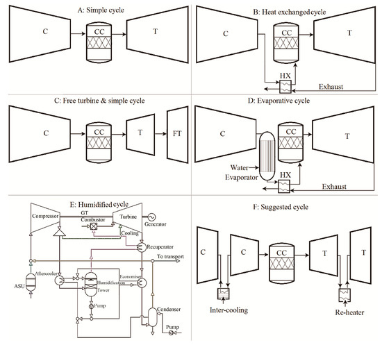
Figure 1.
Schematic diagrams of the cycles (C, CC, T, FT, HX, GT, and ASU stand for compressor, combustion chamber, turbine, free turbine, heat exchanger, gas turbine, and air separation unit, respectively).
The concept of inferring the optimal CARSOXY blend was first established in a 2017 paper [18]. Optimizing CARSOXY molar fractions (Argon, CO2, H2O, fuel, O2) is based on finding a balanced composition to reduce NOx emissions, control CO2, and increase cycle efficiency while avoiding turbine overheating. Essentially, O2 is utilized to eliminate NOx emissions, CO2 works as a diluent to prevent turbine overheating, and argon and H2O increase the working fluid’s overall heat capacity, thus increasing cycle efficiency.
However, choosing the optimal blend is based on testing a random number of blends with random proportions without indicating the effect of each component (i.e., carbon dioxide, argon, and steam) on the cycle efficiency. On the other hand, this paper studies combined and individual effects of each component of the CARSOXY components on the cycle efficiency. Based on that, a new novel optimal blend is selected. The choice is based on correlating three intervals of variable molar fractions of carbon dioxide, argon, and steam in a three-dimensional efficiency surface. This approach essentially visualizes the highest cycle efficiency as the highest peak on the efficiency surface within the tested intervals of molar fractions. Therefore, the corresponding molar fractions (to the highest peak) can then be chosen as the optimal blend. The new suggested blend in this paper has the molar fractions of 47% argon, 10% carbon dioxide, 10% H2O, and 33% oxyfuel. Wet and dry compressions are also studied and compared in this paper for both air and CO2-argon-steam mixtures amongst other heat recovery and humidified injection techniques.
Moreover, the original CARSOXY analysis [18] was based only on one cycle arrangement (humidified gas turbine cycle, Figure 1). In contrast, this paper analyzes four other gas turbine arrangements (namely, simple, heat exchanged, free turbine and simple, and evaporative, Figure 1). These are analyzed with reference to the original cycle [18] under various intervals and working conditions. Therefore, this paper provides a new CARSOXY blend, which offers higher efficiency in a more efficient cycle arrangement (heat exchanged cycle).
In addition to the efficiency increase of the CARSOXY gas turbine, which is demonstrated in this paper, economic sustainability was evaluated by reference [19]. It was reported that the CARSOXY cycle was demonstrated to be more economically sustainable than the air-driven gas turbine. The modified internal rate of return (MIRR) of the CARSOXY cycle is approximately 2.2% higher than that for the air-driven cycle [19]. Moreover, the Profitability Index (PI) of the CARSOXY cycle is 1.72, while it is only 1.28 for the air-driven cycle [19]. Moreover, as reported in the literature [19], CARSOXY gas turbine cycles facilitate excellent opportunity to utilize water-gas-shift (WGS) reactors to reduce carbon monoxide emissions and potentially increase syngas production if integrated with biomass gasification, as reported by the reference [26]. Other integration scenarios also demonstrate high potential to couple CARSOXY power plant with liquid chemical looping gasification (LCLG) systems such as those reported by the references [27,28].
This paper’s results are expected to contribute to the development of units capable of using CARSOXY blends for their integration with CCS systems to deliver power at the same efficiencies as those produced by current air-based units without carbon sequestration. This will economically motivate industrial developers to allocate CCS technologies for the decarbonization of large-scale processes. This paper’s novelty appears in selecting a new novel CARSOXY blend that provides an additional 10% increase in the cycle efficiency compared to the original CARSOXY blend, reported by the reference [18]. This paper’s new suggested blend has the molar fractions of 47% argon, 10% carbon dioxide, 10% H2O, and 33% oxyfuel. This paper’s second novelty aspect is identifying the optimal operating conditions in which CARSOXY cycles demonstrate superior performance compared to air-driven cycles.
At those conditions, CARSOXY increases cycle efficiency by up to 12% compared to air-driven cycles. The CARSOXY heat exchanged cycle has the highest efficiency among the other CARSOXY cycles in the compressor pressure ratio domain of 2–3 and 6–10, whereas, at 3–6, the humidified cycle has the highest efficiency.
2. Setup
The results in this paper are based on a MATLAB code that has been developed to conduct the cycle analysis for both CARSOXY and air-driven gas turbines. Assuming the stoichiometric condition of an equivalence ratio of one, Equation (1) shows the stoichiometric reaction for CO2-argon-steam mixture:
The produced results obtained from the code are based on the higher heating values (HHV) of methane combustion, driven using Equations (2)–(6) [29]:
Equations (7)–(11) show the reference equations used to drive heat capacities of the CO2-argon-steam mixture for each stage [30]:
The parametric study is conducted to produce results in a three-dimensional surface rather than two-dimensional curves to consider the combined effects of two variables, such as inlet temperature and pressure ratio. Wet and dry compressions are mathematically modeled by adding the molar fraction of steam to the CO2-Ar mixture before and after the compression stage, respectively. Wet compression refers to a direct steam feed through the compressor intake. Neither the effect of steam temperature nor the implementation methods are addressed in this paper. The first set of results are plotted for the cycle efficiency with respect to both the compressor pressure ratio variation within the range of 2–10 and the compressor inlet temperature variation within the range of 250–600 K at a constant turbine inlet temperature of 1900 K. Equations (12) and (13) show the specific fuel consumption (SFC) and the cycle efficiency (η):
To obtain the most realistic simulation of the overall performance, the ratios of pressure losses with respect to the stage inlet pressure in the combustion chamber, the heat exchanger cold side, the evaporator, the heat exchanger hot side, and the exhaust are considered as 0.02, 0.03, 0.02, 0.04, and 0.03, respectively [31]. Besides, efficiencies are also taken into account. The compressor and the turbine’s isentropic efficiencies are assumed to be 0.85 and 0.87, respectively, and mechanical and combustion efficiencies are assumed to be 0.99 and 0.98, respectively [31]. The evaporator efficiency is assumed to be 0.87, and the heat exchange effectiveness is assumed to be 0.9 [31]. Average values are chosen since this study aims to obtain indications for as many cases as possible rather than specific values for a particular case. The remaining parameters involved in the cycle analysis, such as WC, and the stagnation conditions at the inlets and the outlets of each stage are calculated using conventional cycle analysis [31]. Some of the equations used for gas turbines are especially derived and implemented in the code, such as those used to calculate the combustion chamber’s inlet temperature T0.1′ for each cycle. As shown in Figure 1, for the simple cycle, the working fluid is initially compressed in the compressor (C) to be delivered to the combustion chamber (CC), which releases flue gases to be expanded to the turbine (T). Similarly, the heat exchanged cycle follows the same cycle arrangement as that for the simple cycle, however, after leaving the compressor and before entering the combustion chamber, the working fluid is preheated against the flue gases in the heat exchanger (HX). For the free turbine and simple cycle, the working fluid is compressed in the compressor, combusted in the combustion chamber, and finally expanded in the turbines and the free turbine (FT). For the evaporative cycle, the working fluid is compressed in the compressor, and steam is added to the working fluid in the evaporator. The working fluid is then preheated in the heat exchanger against the flue gases before it enters the combustion chamber and is finally expanded in the turbine. For the humidified cycle, the details of the cycle design can be found in the reference [18]. Heat capacity variation with respect to temperature in the compression and the expansion stages of the CARSOXY blends is studied for three blends, shown in Table 1. Moreover, the variation of the molar fraction of argon and CO2 is studied with respect to the cycle efficiency.

Table 1.
Compositions of the blends (blend number as in 17).
Validation of the code is performed in two parts. The cycle analysis part of the code is tested against two particular case studies by Saravanamutto et al. [22]. The cases are (1) air-driven free turbine and simple cycle and (2) air-driven heat exchanged cycle. The isentropic heat capacity and the heat capacity ratio of air at the compression stage are suggested to be 1.005 kJ/(kg∙K) and 1.4, respectively. At the expansion, these values are set as 1.148 kJ/(kg∙K) and 1.33, respectively. The results of the code exactly match the results of the case study. The second part of the validation is for CARSOXY-driven gas turbines. It is performed via testing the code for CARSOXY gas turbine cycles to reproduce the heat capacity readings of blends 58, 79, and 27 (Table 1) against the results from Al-Doboon et al. [18] under the same conditions of analysis, i.e., 10 bar and 900 K. The ratios of heat capacities for blends 58, 27, and 79 are 1.22, 1.23, and 1.22, respectively, while those produced via the code are 1.25, 1.26, and 1.25, respectively. Thus, the MATLAB code results diverge from those of Al-Doboon et al. 17 by only 2.4%.
3. Results
3.1. Efficiency Results with Respect to Variable Compressor Inlet Temperatures and Compressor Pressure Ratio
The CARSOXY-driven simple cycle with wet compression shows relatively lower efficiency than the air-driven simple cycle. It falls behind it by almost 2% in all conditions, as shown in Figure 2a.
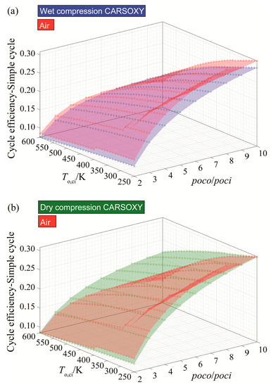
Figure 2.
Efficiency results for the simple cycle using (a) wet compression and (b) dry compression.
However, the dry compression of the CARSOXY-driven simple cycle maintains a relatively high efficiency in the domain of 300–600 K and 2–6 compressor pressure ratio, as shown in Figure 2b. In comparison, the efficiency of the air-driven simple cycle dramatically drops at this domain, with the CARSOXY-driven cycle’s efficiency being higher than the air-driven cycle by up to 7%. Nevertheless, at lower pressure ratios and compressor inlet temperatures, the air-driven simple cycle maintains higher efficiency than the CARSOXY-driven cycle.
Figure 3a shows that the CARSOXY-driven heat exchanged cycle with wet compression has up to 6% higher efficiency relative to the air-driven cycle at the domain of 5–10 compressor pressure ratio and 250–490 K compressor inlet temperature. Outside this domain, the air-driven cycle has higher efficiency. The same can be said about Figure 3b for dry compression, where the efficiency increases by up to 12% in the higher compressor pressure ratio domain of 4–10.
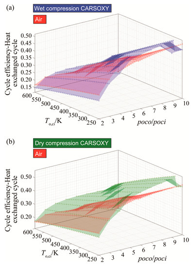
Figure 3.
Efficiency results for the heat exchanged cycle using (a) wet compression and (b) dry compression.
For CARSOXY-driven free turbine and simple cycle, the efficiency relative to the air-driven is higher only at high compressor inlet temperatures above 480 K for wet compression and above 360 K for dry compression, as Figure 4a,b shows. Outside of these domains, the efficiency of the air-driven cycle is higher.
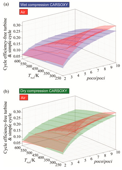
Figure 4.
Efficiency results for the free turbine and simple cycle arrangement cycle using (a) wet compression and (b) dry compression.
For the CARSOXY-driven evaporative cycle, the efficiency is higher than the air-driven cycle in all conditions by up to 6% for wet compression and 12% for dry compression, as shown in Figure 5a,b.
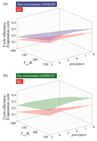
Figure 5.
Efficiency results for the evaporative cycle using (a) wet compression and (b) dry compression.
As can be seen in Figure 6a,b, the CARSOXY humidified cycle has higher efficiency at both compression conditions (dry and wet). However, the effect on efficiency becomes more significant as the compressor inlet temperature increases. The CARSOXY humidified cycle’s efficiency is lower than that for the air-driven cycle at low temperatures (i.e., at a temperature of 250 K and pressure ratios 6–8 bar for wet compression).
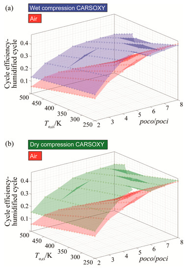
Figure 6.
Efficiency results for the humidified gas turbine cycle using (a) wet compression and (b) dry compression.
To sum up this set of results, dry compression of CARSOXY-driven cycles increases the efficiency in the previously mentioned domains relative to the air-driven cycles. Figure 7 compares the five CARSOXY-driven cycles between each other. The heat exchanged cycle has the highest efficiency among the cycles in the pressure ratio domains of 2–3 and 6–10, whereas, at 3–6, the humidified cycle has the highest efficiency. The evaporative cycle has intermediate efficiency values, while the simple cycle and the free turbine and simple cycle have the lowest efficiencies among the five cycles.
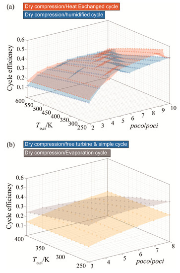
Figure 7.
Efficiency results for all cycles with dry compression, for (a) the heat exchanged and humidified cycles), (b) the free turbine & simple cycle and the evaporative cycle).
3.2. Efficiency Results with Respect to Variable Molar Fractions of Ar, CO2, and H2O
The results are produced for a range molar fractions of Ar, CO2, and H2O, where, in each case, a molar fraction of 25% is maintained constant for the oxy-fuel. The results in Figure 8 show that the molar fraction of argon is directly proportional to the cycle efficiency and that its effect on increasing the cycle efficiency becomes more significant as the molar fraction of CO2 decreases. Moreover, the impact of increasing the molar fraction of H2O is linearly inverse to the cycle efficiency.
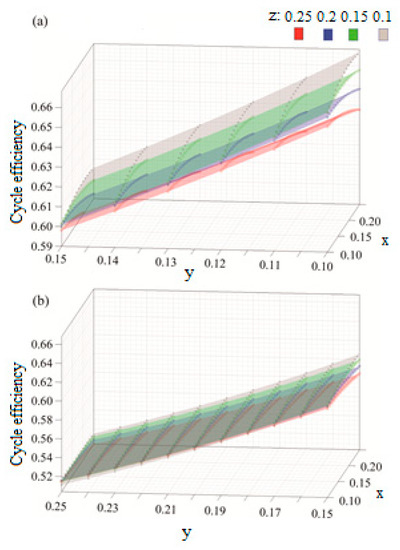
Figure 8.
Efficiency results with respect to variable molar fractions of x: argon, y: H2O and z: CO2, for (a) y = [0.1–0.15] and (b) y = [0.15–25].
Therefore, a new blend is proposed with the molar fractions of 47: argon, 10: H2O, 10: CO2, and 33: oxy-fuel. This blend has been tested against blend 58, which was suggested by the reference [18] (25: argon, 23: H2O, 19: CO2, and 33: oxy-fuel). Results shown in Figure 9 indicate that the blend can theoretically increase the efficiency to values greater than those for the blend (58) by up to an additional 10%. The effect of the suggested blend on increasing efficiency is significant only at low compressor inlet temperatures. In fact, at higher temperatures (i.e., greater than 450 K), blend 58 remains superior in terms of cycle efficiency.
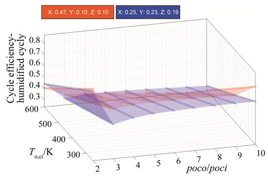
Figure 9.
Efficiency results for blend 58 and the new blend.
3.3. Efficiency Results with Respect to Variable Turbine Inlet Temperatures
The effect of increasing the turbine inlet temperature of the heat exchanged, the free turbine and simple cycle, and the evaporative cycles follows the conventional air-driven cycles pattern as it increases the cycle efficiency. However, the efficiency of the humidified cycle fluctuates as the turbine inlet temperature increases. Generally, cycle efficiencies maintain the same order of magnitudes as those plotted with respect to variable compressor inlet temperature, where the heat exchange cycle has the highest efficiency amongst the five cycles, as shown in Figure 10a.
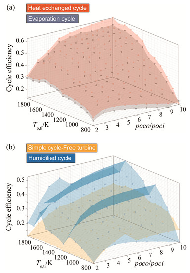
Figure 10.
Efficiency results for (a) the heat exchanged cycle and the evaporative cycle and (b) the humidified cycle and the free turbine and simple cycle arrangement with respect to turbine inlet temperature variation.
As shown in Table 2, the following results are a sample of increasing turbine temperatures from 800 K to 1200 K at a compressor pressure ratio of 3 and an inlet temperature of 298 K.
Table 2.
A sample results of increasing turbine temperatures from 800 K to 1200 K.
However, turbine inlet temperature increases are highly limited by material limitations of the turbine blades at the turbine stage, especially when the temperature is already at a relatively high value.
4. Conclusions
CARSOXY-driven cycles can increase the cycle efficiency in the right domains of operating conditions. These domains are identified for each cycle. The CARSOXY heat exchanged cycle has the highest efficiency among the other CARSOXY cycles in the compressor pressure ratio domains of 2–3 and 6–10, whereas, at 3–6, the humidified cycle has the highest efficiency. Efficiency increase can be up to 12% using a heat exchanged cycle with dry compression. This is defined as the optimal arrangement since it is more efficient than an air-driven cycle at any operating condition. Additionally, the effect of increasing turbine temperatures is studied for the CARSOXY cycles. As the temperature increases from 800 K to 1200 K, the cycle efficiencies increase by 14%, 14%, and 15% for the heat exchanged, the humidified, and the evaporative cycles, respectively. The results show that the cycle efficiency using CARSOXY blends can be increased as the compressor inlet temperature decreases and the turbine inlet temperature increases. It can be concluded that a compressor inter-cooling system and a turbine re-heater can be used for CARSOXY-driven cycles. However, additional turbine re-heater and compressor inter-cooling systems would penalize the compactness of the cycle. Compressor inter-cooling systems may involve water, which would partially lead to wet compression. Based on the results, wet compression reduces the cycle efficiency. Therefore, special care needs to be taken in choosing and implementing the inter-cooling system. An additional 10% increase of the cycle efficiency can be theoretically achieved by utilizing a new blend with the molar fractions of 47% argon, 10% carbon dioxide, 10% H2O, and 33% oxy-fuel at low compressor inlet temperatures. Increasing argon’s molar fraction and decreasing the molar fraction of H2O have dominant effects on improving the overall cycle efficiency. However, increasing argon’s molar fraction is challenging, as air is composed of 78.12% nitrogen, 20.95% oxygen, and only 0.93% argon. Therefore, it is crucial to carefully choose a suitable air separation unit to provide the necessary amount of argon for the new blend.
Author Contributions
Conceptualization, O.F.A., P.B. and A.V.M.; methodology, O.F.A., P.B. and A.V.M.; software, O.F.A., P.B. and A.V.M.; validation, O.F.A., P.B. and A.V.M.; formal analysis, O.F.A., P.B. and A.V.M.; investigation, O.F.A., P.B. and A.V.M.; resources, O.F.A., P.B. and A.V.M.; data curation, O.F.A., P.B. and A.V.M.; writing—original draft preparation, O.F.A., P.B. and A.V.M.; writing—review and editing, O.F.A., P.B. and A.V.M.; visualization O.F.A., P.B. and A.V.M.; supervision, P.B. and A.V.M.; project administration, O.F.A., P.B. and A.V.M.; funding acquisition, O.F.A., P.B. and A.V.M. All authors have read and agreed to the published version of the manuscript.
Funding
This research was funded by the Welsh European Funding Office (WEFO) through its program “Flexible Integrated Energy Systems (FLEXIS)”, grant number 80835” and The APC was funded by Cardiff university-School of engineering.
Conflicts of Interest
The authors declare no conflict of interest.
Nomenclature
| A | Molar fraction of fuel in CARSOXY mixture |
| B | Molar fraction of the oxygen in CARSOXY mixture |
| CxHy | Hydrocarbon fuel, methane (x: 1 and y: 4) |
| Cpmix | Specific heat at constant pressure of a mixture/J∙mol−1∙K−1 |
| Cp(i) | Specific heat at constant pressure of ith component in a mixture/J∙mol−1∙K−1 |
| Cvmix | Specific heat of a mixture at constant volume/J∙mol−1∙K−1 |
| Change in heat capacity at constant pressure/J∙mol−1∙K−1 | |
| f | Fuel to air ratio |
| HHVT0.1′ | Higher heating value at the combustion inlet temperature/kJ∙kg−1 |
| HHVT0.2′ | Higher heating value at the combustion outlet temperature/kJ∙kg−1 |
| Hwf,T0.2′ | Enthalpy of the working fluid at the combustion outlet temperature/kJ∙mol−1 |
| Hwf,T0.1′ | Enthalpy of the working fluid at the combustion inlet temperature/kJ∙mol−1 |
| ∆HReaction, 25 °C | Standard enthalpy change of the combustion reaction |
| ∆Hproducts | Enthalpy of products/kJ∙mol−1 |
| ∆Hreactant | Enthalpy of reactants/kJ∙mol−1 |
| ∆HReaction,T0.1′ | Enthalpy of the combustion reaction at the combustion inlet temperature /kJ∙mol−1 |
| Enthalpy of H2O at the combustion inlet temperature/kJ∙kg−1 | |
| LHVT0.1′ | Lower heating value at the combustion inlet temperature/kJ∙kg−1 |
| Molecular weight of methane (x: 1 and y: 4)/g∙mol−1 | |
| Molecular weight of H2O/g∙mol−1 | |
| Number of moles of H2O produced due to combustion | |
| Number of moles of hydrocarbon fuel in CARSOXY mixture | |
| poco/poci | Compressor pressure ratio |
| Rmix | Gas constant of a gaseous mixture /J∙mol−1∙K−1 |
| ri | Volume fraction of ith |
| SFC | specific fuel consumption |
| To,ci | Compressor inlet temperature/K |
| To,ti | Turbine inlet temperature/K |
| Wt | Turbine specific work/kJ∙kg−1 |
| WC | Specific work required from the turbine to run the compressor/kJ∙kg−1 |
| X | Molar fraction of the Argon in CARSOXY mixture |
| xi | Molar fraction of ith component in a mixture |
| Y | Molar fraction of H2O in CARSOXY mixture |
| γmix | Heat capacity ratio of a mixture |
| η | Cycle efficiency |
| μmix | Average molecular weight of a mixture/g∙mol−1 |
| μi | Molecular weight of ith component in a mixture/g∙mol−1 |
| σ | Molar fraction in products |
References
- Committee on Climate Change. UK regulations: The Climate Change Act—Committee on Climate Change. 2019. Available online: https://www.theccc.org.uk/tackling-climate-change/the-legal-landscape/the-climate-change-act/ (accessed on 5 June 2019).
- Gibbins, J.; Chalmers, H. Carbon capture and storage. Energy Policy 2008, 36, 4317–4322. [Google Scholar] [CrossRef]
- Pioro, I.; Duffey, R.B.; Kirillov, P.L.; Pioro, R.; Zvorykin, A.; Machrafi, R. Current Status and Future Developments in Nuclear-Power Industry of the World. J. Nucl. Eng. Radiat. Sci. 2019, 5, 024001. [Google Scholar] [CrossRef]
- Gad-Briggs, A.; Pericles, P.; Nikolaidis, T. Analyses of the Costs Associated with Very High Turbine Entry Temperatures in Helium Recuperated Gas Turbine Cycles for Generation IV Nuclear Power Plants. J. Nucl. Eng. Radiat. Sci. 2019, 5, 011019. [Google Scholar] [CrossRef]
- Ubald, B.N.; Tucker, P.G.; Cui, J.; Watson, R.; Shahpar, S. Numerical Analysis of an Instrumented Turbine Blade Cascade. J. Turbomach. 2019, 141, 051013. [Google Scholar] [CrossRef]
- Yilmaz, I.; Yilmaz, H.; Cam, O. An experimental study on premixed CNG/H2/CO2 mixture flames. Open Eng. 2018, 8, 32–40. [Google Scholar] [CrossRef]
- Al-Mamoori, A.; Krishnamurthy, A.; Rownaghi, A.A.; Rezaei, F. Carbon capture and utilization update. Energy Technol. 2017, 5, 834–849. [Google Scholar] [CrossRef]
- Kosowska-Golachowska, M. Thermal analysis and kinetics of coal during oxy-fuel combustion. J. Therm. Sci. 2017, 26, 355–361. [Google Scholar] [CrossRef]
- Lele, F.; Wu, Y.; Xu, K.; Zhang, H.; Zhang, Y.; Zhang, M. Coal-Derived Soot Behaviors in O2/N2 and O2/CO2 Atmospheres, Studied through a 1-D Transient Coal Combustion Model. Energy Fuels 2019, 33, 3620–3629. [Google Scholar]
- Saeed, M.; Goodarzi, M.; Safaei, M.R. Comparative study of the performance of air and geothermal sources of heat pumps cycle operating with various refrigerants and vapor injection. Alexandria Eng. J. 2020. [Google Scholar] [CrossRef]
- Nima, B.; KazımSömek, S.; Özalevli, C.C.; Baker, D.; Tarı, İ. Numerical analysis of phase change material characteristics used in a thermal energy storage device. Heat Transf. Eng. 2018, 39, 268–276. [Google Scholar]
- JiHo, A.; Jeong, J.H.; Kim, T.S. Performance Enhancement of a Molten Carbonate Fuel Cell/Micro Gas Turbine Hybrid System with Carbon Capture by Off-Gas Recirculation. J. Eng. Gas Turbines Power 2019, 141, 041036. [Google Scholar]
- Georgescu-Roegen, N. Energy analysis and economic valuation. In Green Accounting; Routledge: Morgantown, WV, USA, 2018; pp. 75–110. [Google Scholar]
- Ibrahim Thamir, K.; Mohammed, M.K.; Awad, O.I.; Abdalla, A.N.; Basrawi, F.; Mohammed, M.N.; Najafi, G.; Mamat, R. A comprehensive review on the exergy analysis of combined cycle power plants. Renew. Sustain. Energy Rev. 2018, 90, 835–850. [Google Scholar] [CrossRef]
- Tailu, L.; Liu, J.; Wang, J.; Meng, N.; Zhu, J. Combination of two-stage series evaporation with non-isothermal phase change of organic Rankine cycle to enhance flue gas heat recovery from gas turbine. Energy Convers. Manag. 2019, 185, 330–338. [Google Scholar]
- Roberto, C.; Giordano, L. Upgrading existing gas-steam combined cycle power plants through steam injection and methane steam reforming. Energy 2019, 173, 229–243. [Google Scholar]
- Mahdiyeh, K.; Mohamed, A.A.; Brandauer, W. Recuperation of regenerative braking energy in electric rail transit systems. IEEE Trans. Intell. Transp. Syst. 2019. [Google Scholar] [CrossRef]
- Ali, A.; Gutesa, M.; Valera-Medina, A.; Syred, N.; Ng, J.; Chong, C.T. CO2-Argon-Steam oxy-fuel (CARSOXY) combustion for CCS inert gas atmospheres in gas turbines. Appl. Therm. Eng. 2017, 122, 350–358. [Google Scholar]
- Alrebei, O.; Valera-Madeina, A. Techno-Economics of CO2-Argon-Steam Oxy-Fuel (CARSOXY) Gas Turbines, 3rd ed.; ICCE: Stavanger, Norway, 2019. [Google Scholar]
- Luo, X.; Wang, M. Optimal operation of MEA-based post-combustion carbon capture for natural gas combined cycle power plants under different market conditions. Int. J. Green. Gas Control 2016, 48, 312–320. [Google Scholar] [CrossRef]
- Mohamed, K.; Gros-Bonnivard, R.; Jaud, P.; Valle-Marcos, J.; Jean-Marc, A.; Bouallou, C. Pre-combustion, post-combustion and oxy-combustion in thermal power plant for CO2 capture. Appl. Therm. Eng. 2010, 30, 53–62. [Google Scholar]
- Saravanamuttoo, H.I.H.; Frederick, G.; Rogers, C.; Cohen, H. Gas Turbine Theory; Pearson Education: London, UK, 2001. [Google Scholar]
- Biskamp, D. Magnetohydrodynamic Turbulence; Cambridge University Press: Cambridge, UK, 2003. [Google Scholar]
- Davidson, P.A. An Introduction to Magnetohydrodynamics; Cambridge University Press: Cambridge, UK, 2002; p. 781. [Google Scholar]
- Freidberg, J.P. Plasma Physics and Fusion Energy; Cambridge University Press: Cambridge, UK, 2008. [Google Scholar]
- Sarafraz, M.M.; Safaei, M.R.; Jafarian, M.; Goodarzi, M.; Arjomandi, M. High Quality Syngas Production with Supercritical Biomass Gasification Integrated with a Water–Gas Shift Reactor. Energies 2019, 12, 2591. [Google Scholar] [CrossRef]
- Reza, S.M.; Leon, A.S.; Khaled, U.; Goodarzi, M.; Meer, R. Energetic Analysis of Different Configurations of Power Plants Connected to Liquid Chemical Looping Gasification. Processes 2019, 7, 763. [Google Scholar]
- Sarafraz, M.M.; Jafarian, M.; Arjomandi, M.; Nathan, G.J. Potential use of liquid metal oxides for chemical looping gasification: A thermodynamic assessment. Appl. Energy 2017, 195, 702–712. [Google Scholar] [CrossRef]
- Irvin, G.; Yetter, R.A.; Glumac, N.G. Combustion; Academic Press: Cambridge, MA, USA, 2014. [Google Scholar]
- Kalyan, A.; Puri, I.K.; Jog, M.A. Advanced Thermodynamics Engineering; CRC Press: Boca Raton, FL, USA, 2011. [Google Scholar]
- McDonald Colin, F.; Wilson, D.G. The utilization of recuperated and regenerated engine cycles for high-efficiency gas turbines in the 21st century. Appl. Therm. Eng. 1996, 16, 635–653. [Google Scholar] [CrossRef]


© 2020 by the authors. Licensee MDPI, Basel, Switzerland. This article is an open access article distributed under the terms and conditions of the Creative Commons Attribution (CC BY) license (http://creativecommons.org/licenses/by/4.0/).