Article

Physical Experiment and Numerical Modeling on the Failure Mechanism of Gob-Side Entry Driven in Thick Coal Seam

1
State Key Laboratory for Geomechanics and Deep Underground Engineering, China University of Mining and Technology, Xuzhou 221116, China
2
Graduate School of Engineering, Nagasaki University, 1-14 Bunkyo, Nagasaki 852-8521, Japan
*
Author to whom correspondence should be addressed.
Energies 2020, 13(20), 5425; https://doi.org/10.3390/en13205425
Submission received: 7 September 2020 / Revised: 8 October 2020 / Accepted: 13 October 2020 / Published: 17 October 2020
(This article belongs to the Section L: Energy Sources)

Abstract

:
In this paper, a combination of physical model tests and numerical simulations were carried out to explore the overlying strata movement laws, failure mechanism, and cracks evolution of the gob-side entry driven in a thick coal seam. The physical experimental results indicated that the hanging cantilever beam was easily developed above the coal pillar after mining out the 2101 panel, resulting in a larger and stronger stress concentration. The overburden loads acting on the coal pillar can be greatly released after the hanging roof strata were cut down with an 18 m cutting line. Additionally, we adopted Universal Discrete Element Code (UDEC) software to investigate the deformation and crack evolution mechanism of the gob-side entry under different conditions. The primary-supported roadway underwent severe deformation, filling with a great quantity of tensile and shear cracks to the inner coal pillar. Both the physical and numerical results proved that the optimized-support parameters combined with roof-cutting measures could effectively guarantee the stability of the gob-side entry. This research can provide valuable guidance for the stability control of the gob-side entry in mines under similar conditions.

1. Introduction

As an essential natural resource, coal is the leading energy source in China, which plays a critical role in the construction and development of the national economy. In the past few decades, the coal reserves in China have been drastically depleted due to large-scale mining. In order to save coal energy consumption, decrease the drivage ratio, and improve roadway maintenance, gob-side entry driving (GED) technology has been extensively employed by many coal mines in China [1,2,3,4]. The roadway is usually mined out along the next goaf with a narrow coal pillar to maintain its stability, and the size of the coal pillar can reduce to approximately 3–5 m width, which saves much of the coal resources [5,6,7]. The traditional GED technologies can be easily applied in these thin coal-seam mining conditions. However, for a fully mechanized caving face with a thick coal seam (FMCF-TCS), with the increase of excavation void, the overlying hard roof strata can severelyfracture and collapse, forming a large hanging roof above the roadway, which causes an abnormal stress concentration and more serious instability problems. Besides, the sudden breakage of the hanging roof can also cause a significant impact load on the pillar, which severely threatens the safety of the roadway [8,9,10,11]. The yield pillar is prone to be destroyed when the overburden rock pressure exceeds its bearing strength, resulting in the instability failure of the roadway [12,13,14,15,16,17]. Therefore, the need for further understanding of the deformation and failure mechanism of the gob-side entry driven in a thick coal seam is significant.
Physical model testing is a popular method for studying the stability of large-scale geotechnical engineering, which can effectively make up for the inadequacy of theoretical analysis, numerical simulation, and field tests [18,19,20,21,22,23]. Li et al. [24] developed a large-scale model to investigate the deformation and failure mechanism of a deep roadway with thick top coal. Ju et al. [9] studied the fracture characteristics and movement laws of the key strata in a super-great mining height longwall face. They pointed out that the strata behaviors strongly depend on the fracture and movement law of the key strata structure. Kang et al. [25] simulated the roof collapse mechanism, abutment pressure distribution, and collapsed roof pattern during the longwall coal retreating mining. They concluded that the large increase of horizontal stress in the center of the potential failure area is a reliable geotechnical precursor for large-scale roof collapse. Zhang et al. [2] identified the roof fracturing features under three immediate roof conditions via physical experiments. They pointed out that the deformation of the retained roadway is associated with support strength, overburden depth, and roof cantilever length. To date, many physical experiments have been carried out to investigate the roof strata fracturing laws and the failure mechanism of the roadway in recent years. Xue et al. [26] studied the deformation, strain, and failure features of the overlying and underlying strata of the multiple-seams mining conditions by large-scale model tests. However, the above-mentioned experimental studies mainly focused on the roof-collapse characteristic, or the deformation failure of the roadway, and fewer model tests have been conducted to explore the interaction between the roof strata behaviors and the stability of the roadway.
Numerical modeling is also an effective and powerful method for studying rock mechanical behaviors in underground coal mine roadways [27,28,29,30,31]. Zhang et al. [5] usednumerical simulation methods to explore the stress responses and failure mechanism of gob-side entry driven in under unstable overlying strata. They proposed a triune coupling support technique to guarantee the stability of the coal pillar. Fan et al. [32] investigated the effect of roof-cutting angle and roof-cutting height on the displacement and stress distribution of the gob-side entry. Gao et al. [33] adopted the discrete element numerical calculation program to investigate the deformation and damage behaviors of the roadway driven along an unstable gob. Zhang et al. [12] simulated the effect of coal pillar width on the stress distribution and deformation characteristics of the gob-side entry using a three-dimensional finite difference program. Bai et al. [3] analyzed the stress evolution and deformation failure mechanism of the gob-side entry by FLAC3D numerical analysis software. Based on the numerical results, they proposed three critical measures to ensure the stability of the entry, including setting reasonable coal pillar width, adopting relevant dynamic support principles, and determining the optimal entry driving time.
Although the above studies have achieved extensive research results in the failure mechanism of gob-side entry, most of them focused on the macroscopic deformation and failure features of the roadway, and little attention has been paid to exploring the micro-crack evolution of the roadway-bearing structure. The objective of this study is to get a better understanding of the instability problems of the gob-side entry driven in a thick coal seam and introduce stability control measures. First, the geological and mining conditions and the roadway support pattern were introduced, and the current deformation features and the internal damage situation of the roadway were investigated by field tests. Then, a large-scale physical model test was conducted to reproduce the mining process of the two panels and roadway, and the overburden rock collapsing characteristics, stress evolution laws, and deformation features of the gob-side entry were analyzed. Finally, UDEC Trigon models were developed to analyze and compare failure characteristics, crack evolution, and the damage mechanism of the gob-side entry under different conditions.

2. Case Study

2.1. Engineering Geological Conditions

Jining Coal Mine is a resource-integrated coal mine, which belongs to Linfen City, Shanxi Province, China. Before resource integration, due to the limitation of early mining technology, the main mineable coal seam was mined by the slicing mining method, resulting in a large amount of unmined high-quality coal resources left in the lower slice and protection coal pillars. Thus, the mine integrated the original working faces, and re-excavated the roadway in the lower coal seam to arrange the new working faces to improve the recovery of the coal.
The coalfield is located in the south of Lvliang Mountain, with topography features of high in the middle, and low in the north and south. The area of the coal mine is about 17.69 m2, and the geological coal reserves are about 0.207 billion tons. The strata in the mining area are generally monoclinic structures inclined to the west, dominated by the fold structure. Few faults and no large-scale magmatism can be observed in this area. The main coal-bearing strata are Taiyuan Formation and Shanxi formations, with a total thickness of about 70–140 m, including two main minable coal seams with a total thickness of 8.4 m and a coal-bearing coefficient of 5.4%.
The researched coalfaces are located in the NO.2 coal seam. The burial depth of the coal seam is about 530 m, with an average thickness of 6.2 m. The immediate roof was the mudstone with a thickness of 9.8 m. The main roof mainly consists of siltstone, medium-fine sandstone, and fine stone, while the floor strata is harder siltstone with a thickness of 5.4 m. The lithology distribution of the roof strata is displayed in Table 1.
Figure 1 shows the working face position relationship and coal mining condition. Currently, the upper slice of the 2106 coalface has been excavated with a mining height of 2.2 m, and there was a 4 m-thick coal seam left in the lower slice. The 2101 panel was mined with a full seam. Finally, there was a 20 m-width coal pillar reserved between the 2101 gob and 2106 upper gob, which looks like an approximate isolated island coal pillar. Thus, in order to recover coal in the lower slice of the 2106 panel, the gob-side driving technology was applied in the current coalface. The roadway was driven along the 2106 gob with a coal pillar of 7 m-width. The roadway will experience a more complex stress environment, which leads to greater challenges for the support work.

2.2. In-Situ Observation of the Deformation and Failure Characteristics of the Roadway

The roadway was arranged along the floor of the coal seam, with a cross-section of 5.2 × 4.0 m2. The roadway was primarily supported by a combination of bolts, cables, and W-shaped steel straps. The high-strength thread steel bolts were applied in the roof, and the two ribs were supported with the high-strength resin bolt of Φ20 × 2200 mm. The inter-row spacing of the roof bolts and rib bolts was 800 mm × 1000 mm. The detailed primary-support parameters were shown in Figure 2a. However, the gob-side entry underwent severe deformation under the primary-support parameters, as shown in Figure 3. The coal-pillar rib was seriously fractured and deformed, appearing to have larger expansion than the panel rib. Besides which, the roof also encountered large-scale sagging deformation (Figure 3c).
Thus, to solve the large deformation problems of the roadway, the mine proposed the optimized-support parameters. First, three Φ17.8 × 7800 mm anchor cables were installed in the roof to strengthen the strength of the roof strata, and the length of the roof bolt was increased to 2.5 m. respectively. In addition, the resin bolts used in the coal-pillar rib were adjusted as the high-strength thread steel bolt of Φ20 × 2200 mm, and two Φ17.8 × 4200 mm anchor cables were installed to improve the bearing capacity of the coal pillar. The detailed support parameters are displayed in Figure 2b.
Unfortunately, field observation indicated that the reinforced support technologies failed to solve the large deformation problems of the roadway. The coal-pillar rib was severely damaged due to the larger loads from the overlayer strata. A digital borehole camera device was used to monitor the internal damage of the coal-pillar rib. Figure 4 shows the probe images of the borehole at different depths. The shallow regions of the coal-pillar rib have severely failed, and some crushed zones, significant fragments, huge through-cracks, and borehole collapse can be observed clearly within a depth of 0–2 m. In the range of 2–4 m, some developed cracks and fractures can also be observed on the wall of the borehole. All of the phenomena demonstrate that the integrity of the coal-pillar rib has been severely destroyed. This was because the overlying strata loads and rotation and sagging of the lateral roof caused the internal stress of the coal pillar to increase sharply, thus exceeding the bearing capacity of the coal pillar. According to the previous studies [34,35,36,37,38,39,40], pre-splitting blasting technology is commonly applied to cut down the lateral roof to release the stress acting on the coal pillar, and the overburden loads can be easily transferred into the gob area. In this research, the key to ensuring the stability of the gob-side entry is to grasp the overhanging roof characteristic and determine an optimal roof-cutting parameter.

3. Physical Simulation Experiment

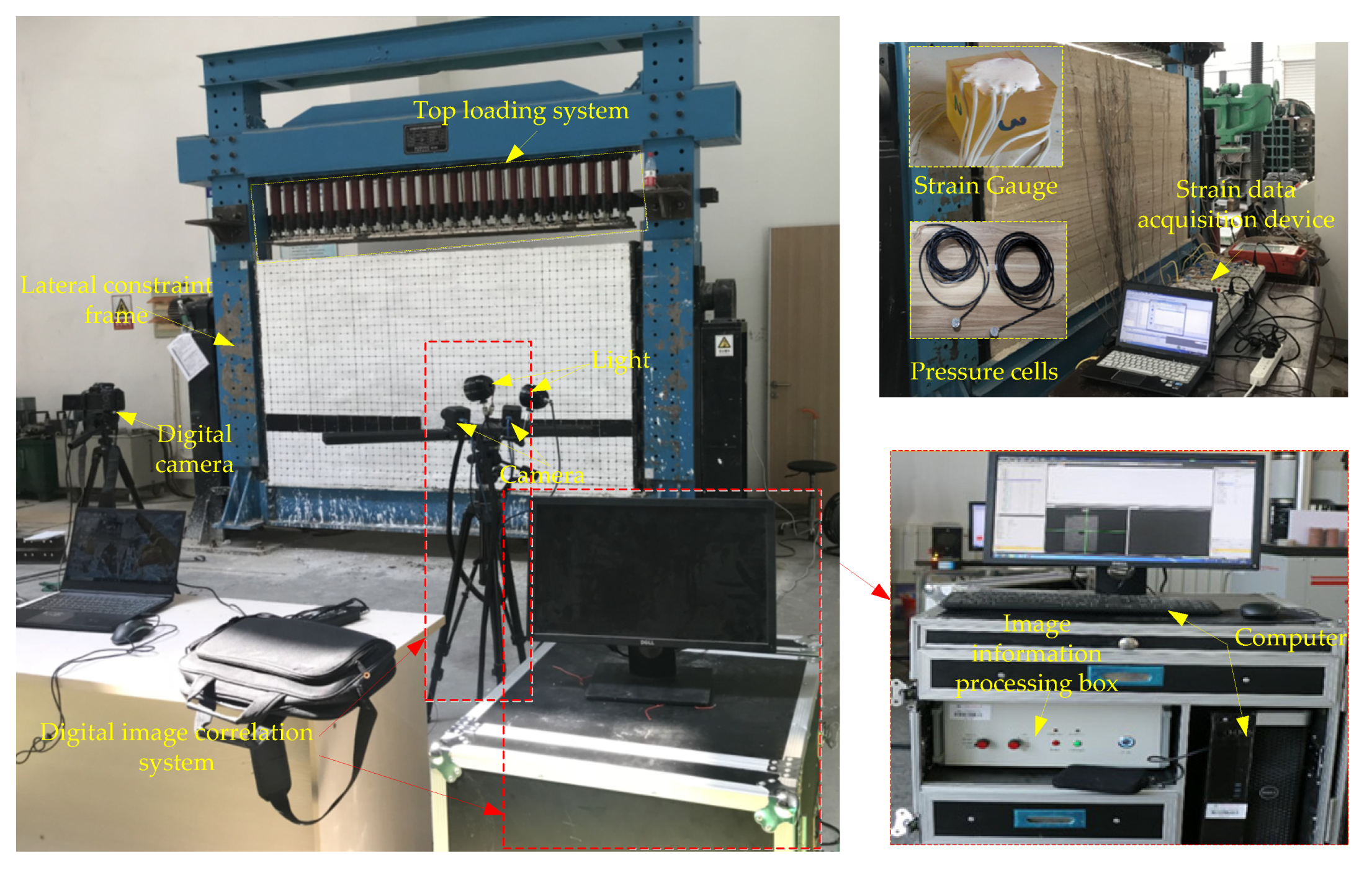
3.1. Introduction of the Physical Model Test System

The test system consists of the plane-stress simulator test frame and the data monitoring system, as shown in Figure 5. The test frame can be applied for a model specimen with a dimension of 2500 mm × 1500 mm × 300 mm (length × height × thickness). The upper of the model specimen is subjected to a vertical load by a hydraulic loading system, and the lateral part is constrained by displacement boundary conditions. During the whole experiment, a constant load of 0.11 MPa was imposed on the top of the model to represent the initial in-situ stress.
The data acquisition system includes the stress monitoring system and the deformation monitoring system. The acquisition of stress data is achieved by the earth-pressure cells and the static strain data collection system. The earth-pressure cells were buried in the coal-pillar region (Figure 6), aiming to record the stress evolution during the mining of two panels and the gob-side entry. A digital image collection (DIC) system was used to measure the displacement change of the roof strata and the roadway. The system consists of two high-speed cameras, an image information processing box, and a high-performance computer. First, the deformed speckle images within the observation field were collected in real-time. Then, the correlation coefficients of all points were determined by using the image correlation algorithm. Finally, by comparing the coordinates of each point before and after deformation, the displacement field and strain field can be obtained.

3.2. Determination of the Similarity Material Ratio

As the theoretical basis of physical model experiments, similarity analysis is very important for the true reproduction of actual geotechnical engineering behaviors. The physical model tests must satisfy some similar criteria, including geometry, boundary stress conditions, strain, displacement, elastic modulus, etc. Considering the actual geological conditions and test equipment, the geometric ratio Cl was set as 60:1 and bulk density ratio was adopted 1.1:1, respectively. Besides which, other similar constants were deduced as follows.
C σ = C E = C c = C l C γ = 66
C μ = C ε = C φ = 1
where Cσ, CE, Cc, Cμ, Cε, Cφ, are the similarity constant of stress, elastic modulus, cohesion, Poisson’s ratio, strain, and internal friction angle, respectively.
In this experiment, we created a mixture of river-sand, calcium carbonate, gypsum, and water, and mixed them by a certain ratio to simulate the in-situ rocks of different strengths. Previous studies [22] proved that it is challenging to ensure all the mechanical properties of similar materials meet the requirements of similar criteria. Therefore, in this study, we mainly chose the strength and elastic modulus of similar materials as important indicators for establishing similar models. The calculated similar materials parameters and proportion schemes are listed in Table 2.

3.3. Physical Model Experiment Results Analysis

3.3.1. Overlying Strata Movement Evolution

Figure 7 shows the roof strata movement and fracture evolution during the mining of the 2016 upper panel. When the coalface advanced 15 m (Figure 7a), an apparent separation crack could be observed in the immediate roof. As the coalface advanced 21 m (Figure 7b), the immediate roof began to break and caved in the gob, forming a voussoir beam structure above the gob. When the coalface advanced 33 m (Figure 7c), the above immediate roof continued to collapse, and a visible separation crack appeared in the main roof strata. When the coalface advanced 45 m (Figure 7d), the main roof began to bend and fracture, and the immediate roof caved in periodically. When the seam had been fully mined out (Figure 7e), the cracks and fractures further developed above the main roof, and the caved zone and fractured zone could be clearly observed. It also can be seen that the immediate roof broke in the form of a cantilever structure and caved in the gob with the advance of the coalface, and finally formed a stable voussoir beam structure above the edge of the coal wall.
The roof movement evolution during the mining of the 2101 panel is presented in Figure 8. The mining direction was from the left to the right of the model, with a mining height of 6.2 m. When the coalface advanced 21 m (Figure 8a), some caved rock and a developed separation in the immediate roof can be observed. When the coalface advanced 26 m (Figure 8b), the immediate roof first collapsed with a caving step-distance of 25 m; the height of the caved zone was about 9 m. When the coalface advanced 45 m (Figure 8c), the immediate roof strata collapsed in the gob for the second time, and apparent bending subsidence can be observed in the upper roof strata. After advancing a short distance (Figure 8d), the main roof began to fracture and collapse; the height of the caved zone increased to 32 m. When the 2101 panel was fully mined out (Figure 8e), a large hanging block was formed above the gob, which acted as a cantilever beam structure.
The above experimental results indicate that: when mining the upper slice of the 2106 panel, the height of the excavation void is relatively smaller. The broken block can easily form a stable voussoir beam structure after a small rotation (Figure 7e). However, when mining the 2101 panel, the height of the excavation void increased to 6.2 m. With the increase of extraction height, the roof strata activity has been enhanced, and the movement space of the overlying rock has been enlarged. Thus, the stable voussoir beam cannot be developed under this condition—due to a large amount of rotation—and an overhanging cantilever beam was formed over the gob, as shown in Figure 8e. On the one hand, the heavy self-weight of the cantilever beam and the larger overburden pressure leads to a stronger abutment pressure in the lower coal pillar. On the other hand, the sudden breakage or rotation of the hanging roof may also result in a more considerable advanced abutment pressure or dynamic pressure, which greatly threatens the stability of gob-side entry [9,10,35]. Thus, it is vital to cut down the hanging roof to provide a more favorable stress environment for the excavation of the roadway.
The physical test results showed that the hanging roof strata mainly included the scope of the immediate roof and the main roof strata. Therefore, the roof-cutting height was set as 18 m, and the roof-cutting angle was adopted 70° for the convenience of on-site construction. The roof structure characteristics of the 2101 coalface after adopting the roof-cutting measure are displayed in Figure 8f. The hanging roof and the overburden strata rotation and slip to the gob after adopting the roof-cutting measure can be observed. As a result, the overburden pressure supported by the lower coal pillar was significantly released.

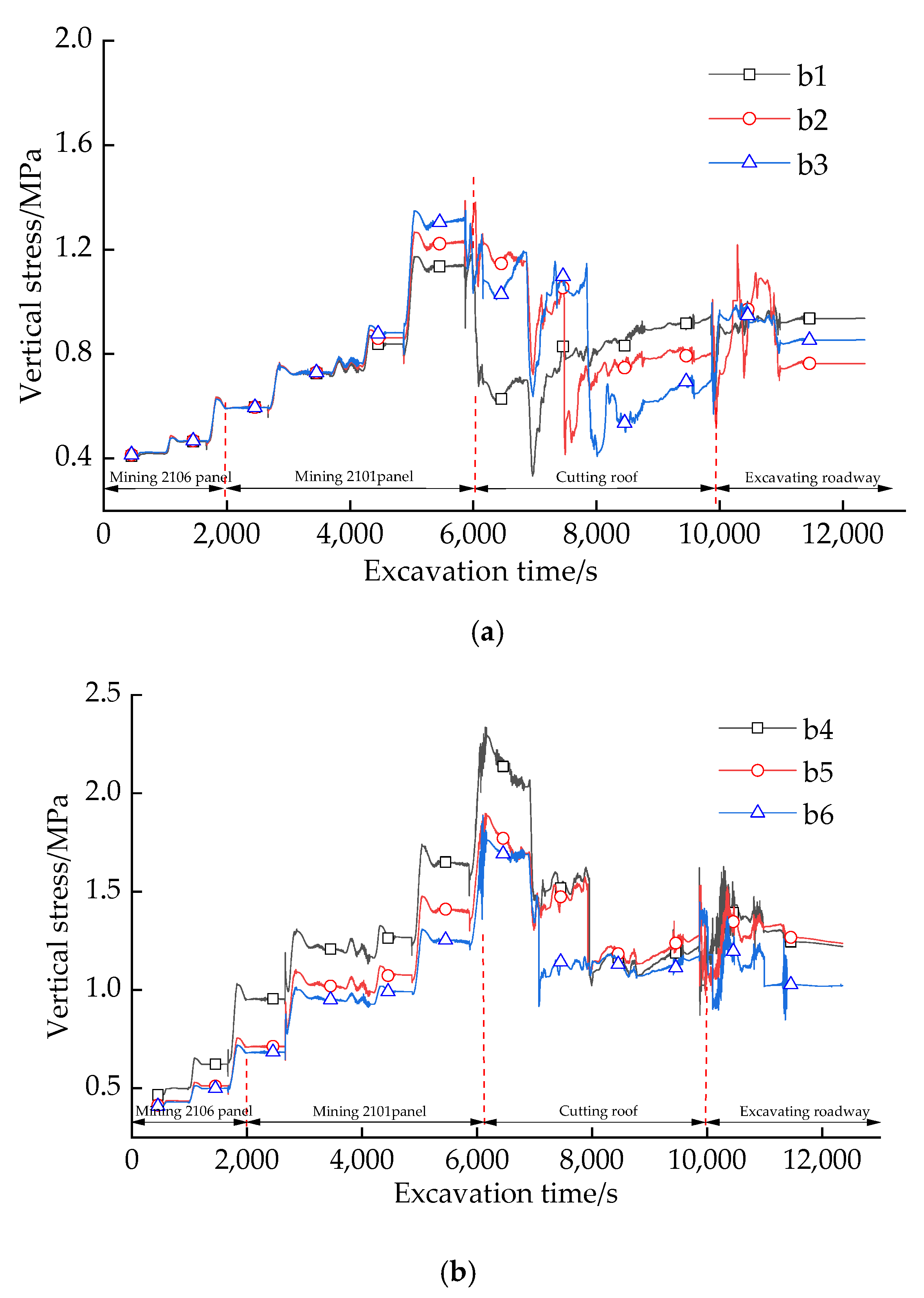
3.3.2. Stress and Deformation Analysis of Gob-Side Entry

Figure 9 shows the stress evolution in the two ribs of the gob-side entry during the excavation of the two panels and the roadway. During the mining of the two panels, the vertical stress gradually increased with the advance of the coalfaces, forming a large stress concentration in the two ribs. It can also be observed that peak stress in the narrow coal-pillar rib (left rib) was more significant than that of the working-face rib (right rib). All of these may attribute to a large cantilever beam overhanging the lower coal pillar (Figure 8e), leading to a more substantial abutment pressure. After cutting the hanging roof, the vertical stress in the coal pillar gradually decrease to a stable state, providing a favorable stress environment for the gob-side entry.
The displacement cloud diagrams of the roadway post-scripted through the DIC system are displayed in Figure 10. At the initial phase (Figure 10a), the contour of the roadway was relatively flat and almost no deformation occurred. Then, the roof and floor started to show slight deformation, as shown in Figure 10b,c. After that, sporadic deformation appeared at the upper ribs of the roadway (Figure 10d). Eventually, several shear cracks can be observed in the upper corners and floor of the roadway (Figure 10f). The final deformation was mainly concentrated at the corners of the rectangular roadway (Figure 10e), and the maximum deformation is 20 mm. The test results indicate that the deformation of roadway driven in the remaining coal pillar can be effectively controlled after adopting the roof-cutting measures.

4. Numerical Simulation Using UDEC

4.1. The UDEC Trigon Approach

The UDEC Trigon method has unparalleled advantages in realistically simulating crack initiation, development, and nucleation compared with the traditional rectangular block [41,42]. In this method, the rock material is treated as an assemblage of the triangular blocks connected by the contacts. The adjacent triangular blocks can separate or slide along the contacts when the stress state of the contacts exceed their tensile or shear strength, representing the occurrence of tensile or shear failure. The basic mechanical interactions between two triangular blocks are summarized in Table 3.

4.2. Calibration of the Simulation Parameters

The mechanical behaviors of rock materials in UDEC are controlled by the microscopic properties of blocks and contacts. Thus, it is necessary to calibrate the micro parameters of the blocks and contacts to match the mechanical properties of the rock mass.
First, the mechanical properties of the intact rock samples were assessed by the laboratory uniaxial compression tests. However, the rock mass usually contains lots of fissures, cracks to joints, and discontinuities, which heavily weaken the strength of the rock mass. Thus, it is unreasonable to equate the mechanical parameters of the intact rock with the rock mass. According to the rock mass classification indicators of rock quality designation (RQD) proposed by Zhang and Einstein [43], the mechanical parameters of the rock mass, including the uniaxial compressive strength and elastic modulus, can be deduced by the following equations. The calculated mechanical parameters of the rock mass are displayed in Table 4.
E m = E r 10 0.0186 R Q D 1.91
σ m = σ r [ E m E r ] n
where Em and σm are the elastic moduli and compressive strength of the intact rock samples, respectively; Er and σr are the elastic moduli and compressive strength of the rock mass; n is a constant, which is often set as 0.63 according to the previous research [44]; RQD is the rock quality designation, which can be determined through the borehole camera images.
Besides this, the calibrated micro parameters of the contacts, such as the normal stiffness (kn) and shear stiffness (ks), can be determined using the following equations.
k n = 10 [ K + 3 4 G Δ z min ]
k s = 0.4 k n
where K and G are the bulk and shear modulus of the blocks, respectively. Δzmin is the minimum distance of the zone adjacent the contact in the normal direction [45].
Finally, we adopted a series of simulated uniaxial compression tests to calibrate the micromechanical properties of the rock material, as shown in Figure 11. The size of the numerical rock sample is 5 m × 10 m (width × height), and the edge of the triangular block is set as 0.3 m, which is consistent with that used in the field models. The calibrated micromechanical parameters are listed in Table 5. In addition, in the model, the in-built “Cable” elements were adopted to simulate the bolts and cables, and “Liner” elements were used to simulate the steel beams. The detailed parameters of the support element are displayed in Table 6.

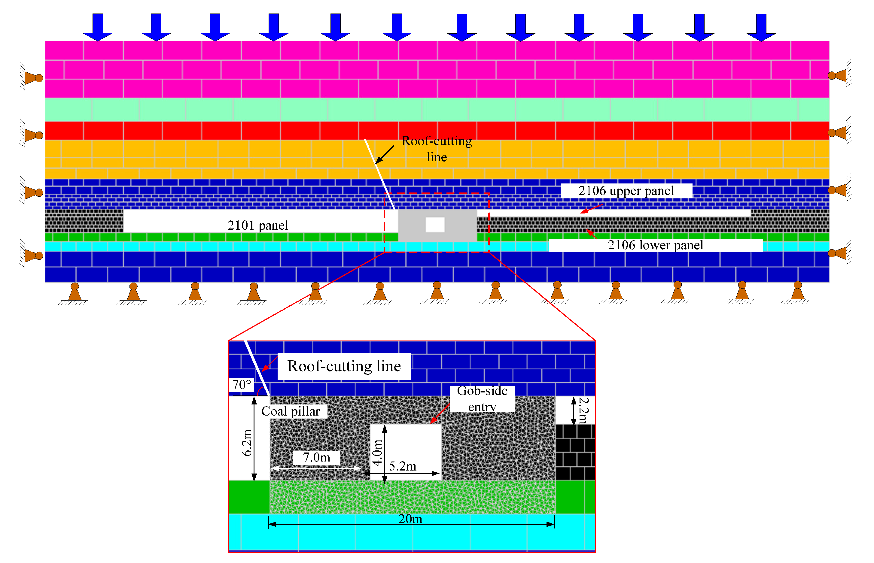
4.3. Model Configuration

In order to further reveal the effect of support parameters and roof-cutting measures on the failure characteristics and crack evolution of the surrounding rock of the gob-side entry, three simulation models were established, including the “primary-support parameters”, the “optimized-support parameters”, and the “optimized-support parameters + roof-cutting”. The dimensions of the calculated model is 200 m (width) × 63 m (height), as shown in Figure 12. The lateral boundaries and bottom boundary were restrained by horizontal displacement and vertical displacement. The upper boundary was applied with a 12 MPa vertical stress to simulate the overburden weight. To improve computational efficiency, the triangular blocks with an average edge length of 0.3 m were only generated in the interest area around the researched roadway. The rest of the domain of the model was discretized into the gradually enlarged rectangular block with increasing distance from the roadway.
During the simulation, the crack development, stress evolution, and deformation failure features of the roadway surrounding rock were analyzed. Also, a FISH program was developed to monitor the changes of shear cracks and tensile cracks in coal pillars, thereby further comparing and analyzing the damage mechanism of coal pillars.

4.4. Numerical Modeling Results Analysis

4.4.1. Failure Characteristics and Crack Evolution

Figure 13 shows the failure modes of the roadway, and the distribution of cracks of the coal pillar is also displayed in detail. As shown in Figure 13a, under the primary-support parameters, the gob-side entry structure was severely damaged due to the larger overburden loads, forming the dangerous V-shaped damage zone in the coal-pillar rib and the roof. Meanwhile, the floor remained quite stable compared with the coal-seam roof, and minor cracks could be observed there. The coal-pillar rib near the 2101 gob underwent larger and more severe deformation than the panel rib near the 2106 upper panel’s gob. Under the load of the hanging cantilever beam, the coal-pillar rib experienced enormous pressure, resulting in a large number of tensile cracks and shear cracks generated inside, which significantly weakened the integrity and strength of the coal pillar. It also should be noted that the number of shear cracks in the coal pillar is significantly more than the number of tensile cracks, implying that the shear failure was the dominant failure pattern.
After adopting reinforced-support measures, the deformation and damage of the roadway were slightly improved, as shown in Figure 13b. The generation of the cracks in the coal pillar was restricted compared with the cracks generated after primary-support. However, the coal-pillar rib still bore enormous concentrated stress induced by the overlying cantilever beam, resulting in severe internal damage to the coal pillar. It is clear that the optimized-support parameters failed to ensure the stability of the coal pillar. Thus, it is essential to relieve the pressure exerted by the overburden on the coal pillar by cutting down the hanging cantilever.
After cutting down the hanging roof for the reinforced roadway (Figure 13c), the deformation and damage degree of the roadway were dramatically improved, and the cracks generated within the coal pillar were also significantly reduced. This is because the disturbance stress acting on the coal pillar was greatly reduced after the fractured hanging roof caved into the gob, which greatly reduced damage to the gob-side entry structure.
To further compare and analyze the evolution of cracks in the coal pillar at different excavation stages, a custom-made FISH program was developed to record the changes of tensile and shear cracks in the coal pillar with the same calculation steps, including the crack numbers and the accumulated length. The crack propagation of the coal-pillar rib at different excavation stages is shown in Figure 14. At the stage of mining the 2106 upper panel, there are almost no tensile or shear cracks generated in the coal-pillar rib, indicating that the excavation of the 2106 upper panel has a negligible effect on the crack development of the coal-pillar rib. When mining the 2101 panel, the abutment pressure applied on the coal-pillar rib increased significantly, resulting in a sharp increase of shear cracks and tensile cracks. After the roadway was excavated out, the concentrated stress formed in coal ribs caused further development of cracks around the roadway. It also should be noted that compared with the primarily supported roadway, the optimized-support roadway had a smaller increment in shear cracks during the roadway excavation stage. This is because the strengthened support improved the bearing performance of the coal pillar, thereby effectively suppressing the development of cracks. After adopting the roof-cutting measures, the propagation and generation of the cracks greatly decreased during the mining of the 2101 panel and the gob-side entry, which may be attributed to the concentrated stress caused by the hanging roof strata being significantly reduced.

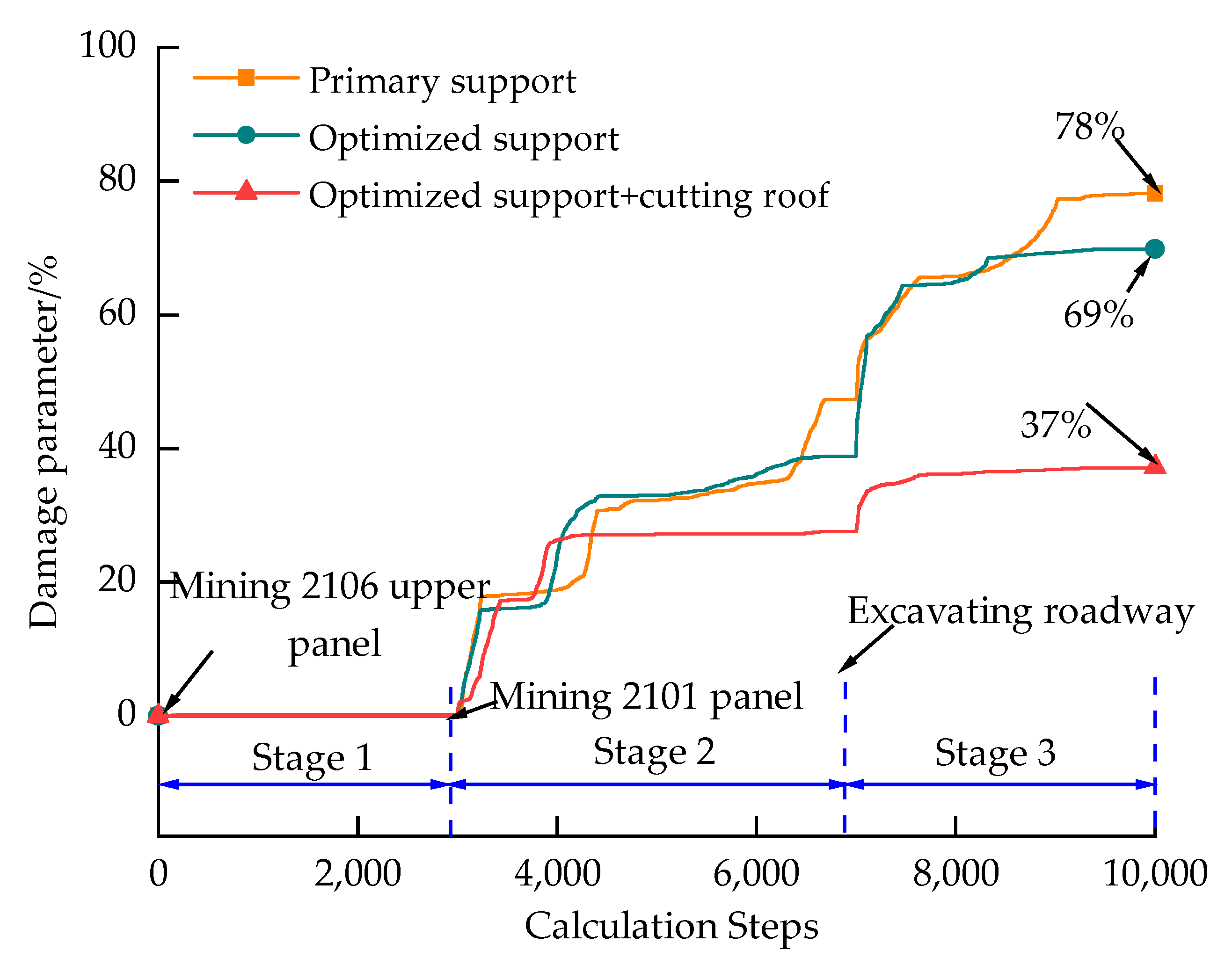
4.4.2. Damage Analysis of the Coal Pillar

To quantitatively evaluate the damage of the coal pillar under different conditions, a damage parameter, D, was proposed as follows [46].
D = L t + L s L c × 100 %
where Lt and Ls is the accumulated increasing length of the tensile cracks and shear cracks, respectively, and Lc is the total length of all contacts.
Figure 15 shows the damage evolution of the coal pillar during the excavation of the two panels and the roadway. During the excavation of the 2106 upper panel, the damage degree is close to zero, implying that the coal pillar underwent almost no damage. This is because that the coal pillar was still in the initial stress zone and not been affected by mining disturbance. When mining the 2101 panel, the damage parameter of the coal pillar increased rapidly and reached a steady value when the movement of the overlying rock achieved a stable state. The cracks initiated and propagated from the edge of the coal pillar, and developed into a deeper area, which gradually deteriorated the integrity of the coal pillar. After the roadway was mined out, the equilibrium state of in-situ stress was broken, resulting in the stress concentration in the two ribs. As a result, cracks further developed around the roadway, which aggravated the damage to the coal pillar. Finally, the damage parameter of the coal pillar supported with the primary-support parameters reached 78%, implying the coal pillar almost lost its bearing capacity. After reinforcing the roof and the coal-pillar rib with the optimized-support parameters, the damage parameters decreased slightly, reaching 69%, which was still very dangerous for the stability of the coal pillar. However, after cutting down the hanging roof for the reinforced roadway, the damage parameters were greatly decreased to 37%, with a reduction of 52%, indicating that the integrity and stability of the coal pillar were significantly improved.

4.4.3. Deformation and Displacement Analysis of the Roadway

Figure 16 presents the simulated displacement vector diagram of the surrounding rock of the roadway. As shown in Figure 16a, the primary-supported roadway had severe uneven deformation, particularly with rib spalling and the roof falling. Also, the deformation in the coal-pillar rib was significantly higher than that of the panel rib, which was due to the coal pillar bearing heavier loads from the hanging roof. After strengthening the roadway with the optimized-support parameters (Figure 16b), the deformations in the roof and coal-pillar rib remained extensive and severe, implying that the optimized-support parameters failed to ensure the stability of the gob-side entry. After adopting the control measures of optimized-support parameters combined with the roof-cutting measures (Figure 16c), the deformation of the roadway tended to be uniform, and no visible collapses or spalling could be observed in the roof and the ribs.
According to the recorded displacement data of the four measuring lines along two ribs, the roof, and the floor of the roadway, the final displacement of the surrounding rock is displayed in Figure 17. It can be observed that the roof and two ribs show more serious deformation, while the deformation of the floor is relatively gentle. As shown in Figure 17a, the coal-pillar rib swelled and deformed seriously under the primary-supported condition, with a maximum horizontal expansion of 590 mm. After adopting the optimized-support parameters and roof-cutting measures, the maximum expansion of the coal-pillar rib was reduced to 92 mm, with a reduction rate of 84.4%. The maximum expansion of the panel rib decreased from 342 mm to 148 mm, with a reduction rate of 56.7%. It also should be noted in Figure 17c that the roof sagging adjacent to the coal-pillar rib was larger than that adjacent to the panel rib, and the maximum roof sagging was 330 mm for the primary-supported roadway. After reinforcing the roadway and cutting down the hanging roof, the maximum roof sagging decreased to 168 mm, with a reduction of 49.1%.

5. Discussion

Previous studies have proven that the overlying strata behaviors of mining a thick coal seam are different from those of a normal mining height [9,10]. The excavation of a thick coal seam can easily lead to a large hanging roof structure above the goaf, and a stable voussoir beam can be easily developed when mining with a normal mining height, which is consistent with the results of the physical experiments (Figure 7 and Figure 8). The large hanging roof leads to more considerable concentrated stress in the underlying rock mass (Figure 9), which greatly threatens the stability of gob-side entry. According to the previous studies [35,36,37], the strong roof strata behaviors could be effectively solved by cutting down the hanging overlying roof strata. The physical experimental results also verified that the loads concentrated on the coal pillar were greatly reduced or released after the hanging cantilever caved into the gob (Figure 9).
The numerical calculation results demonstrated that the primary- and reinforced supported roadway underwent serious deformation, filling with abundant tensile and shear cracks inside the surrounding rock (Figure 13a,b). The cracks evolution indicated that the generation and development of cracks were mainly focused on the stages of mining the 2101 panel and roadway excavation (Figure 14), which greatly weakened the integrity and strength of the coal pillar. The damage evolution of the coal pillar appeared to show a similar trend for the roadway under the primary and reinforced support conditions (Figure 15), implying that the reinforced supported roadway still could not bear the large loads from the overhanging roof strata. However, for the “optimized-support parameters + roof-cutting” condition, the generation and development of cracks were active in the stage of mining the 2101 panel, but the development degree of cracks was significantly restricted during the excavation of the roadway. This could be explained by the formation of the hanging roof after the mining of the 2101 panel having exacerbated the generation and development of cracks, while after the hanging roof was cut down, the large loads caused by the fracture and breakage of the hanging roof were effectively eliminated, thus mitigating the damage to the gob-side entry. Both the physical and numerical results proved that the roadway maintained a good performance after adopting the “optimized-support parameters + roof-cutting” measures.
Notably, this study focuses on the failure mechanism and stability control of the gob-side entry during driving construction. During the 2106 lower panel retreating, the entry will suffer more serious mining-induced loads, and the current “optimized-support parameters + roof-cutting” measures may not guarantee the safety of the roadway. In future studies, we should propose other reinforced support means to deal with the deformation problems of the entry during the panel retreat period.

6. Conclusions

This paper presents a comprehensive investigation of the failure mechanism of the gob-side entry driven in a complex stress environment. Based on the above analysis of the results, the following conclusions were drawn:
(1) The field test showed that the roadway with the primary support was severely deformed, particularly with rib spalling and the roof falling. After reinforcing the roadway with the optimized-support parameters, the borehole camera image demonstrated that the anchorage area of the coal-pillar rib was full of cracks and broken zones, which indicated that the optimized-support pattern failed to maintain the stability of the roadway.
(2) The physical model test indicated that a stable voussoir beam structure could be easily developed above the 2106 upper-slice gob. However, after mining out the 2101 panel, a large hanging cantilever beam was formed over the gob, resulting in a larger and stronger stress concentration in the lower coal pillar. After cutting down the whole hanging roof with an 18 m-height cutting line, the overhanging cantilever beam acting on the coal pillar caved into the gob, which greatly released the stress in the coal pillar and decrease the probability of dynamic disasters.
(3) The simulation results indicated that the primary-supported roadway was seriously damaged with a larger expansion in the coal-pillar rib. The monitored coal pillar was filled with a large number of tensile and shear cracks, and shear cracks played a dominant role. The generation and development of the cracks were mainly concentrated in the stage of mining the 2101 panel and roadway excavation, which gradually weakened the bearing capacity of the coal pillar. The final damage parameter of the coal pillar reached 78%, implying that most regions of coal pillars are severely fractured. After reinforcing the roadway and adopting the roof-cutting measures, the final damage parameter of the coal pillar decreased to 38%, and the integrity and stability of the coal pillar was greatly improved.

Author Contributions

Conceptualization, X.S. and H.J.; methodology, X.S.; software, X.S. and Y.Z.; validation, X.S., H.J. and Z.Z.; formal analysis, Y.G.; investigation, X.S.; writing—original draft preparation, X.S.; writing—review and editing, X.S.; visualization, X.S., Y.G., R.B.; supervision, H.J.; project administration, X.S.; funding acquisition, H.J. All authors have read and agreed to the published version of the manuscript.

Funding

This work is supported by joint Ph.D. program of “double first rate” construction disciplines of CUMT.

Acknowledgments

The authors gratefully acknowledge the financial support from the joint Ph.D. program of “double first rate” construction disciplines of CUMT.

Conflicts of Interest

The authors declare no conflict of interest.

References

  1. Yang, J.; He, M.C.; Cao, C. Design principles and key technologies of gob side entry retaining by roof pre-fracturing. Tunn. Undergr. Space Technol. 2019, 90, 309–318. [Google Scholar] [CrossRef]
  2. Zhang, N.; Yuan, L.; Han, C.L.; Xue, J.H.; Kan, J.G. Stability and deformation of surrounding rock in pillarless gob-side entry retaining. Saf. Sci. 2012, 50, 593–599. [Google Scholar] [CrossRef]
  3. Bai, J.B.; Shen, W.L.; Guo, G.L.; Wang, X.Y.; Yu, Y. Roof deformation, failure characteristics, and preventive techniques of gob-side entry driving heading adjacent to the advancing working face. Rock Mech. Rock Eng. 2015, 48, 2447–2458. [Google Scholar] [CrossRef]
  4. Ma, D.; Duan, H.Y.; Liu, J.F.; Li, X.B.; Zhou, Z.L. The role of gangue on the mitigation of mining-induced hazards and environmental pollution: An experimental investigation. Sci. Total Environ. 2019, 664, 436–448. [Google Scholar] [CrossRef]
  5. Zhang, Y.; Wan, Z.J.; Li, F.C.; Zhou, C.B.; Zhang, B.; Guo, F.; Zhu, C.T. Stability of coal pillar in gob-side entry driving under unstable overlying strata and its coupling support control technique. Int. J. Min. Sci. Technol. 2013, 23, 193–199. [Google Scholar] [CrossRef]
  6. Yang, J.P.; Cao, S.G.; Li, X.H. Failure laws of narrow pillar and asymmetric control technique of gob-side entry driving in island coal face. Int. J. Min. Sci. Technol. 2013, 23, 267–272. [Google Scholar] [CrossRef]
  7. Zha, W.H.; Shi, H.; Liu, S.; Kang, C.H. Surrounding rock control of gob-side entry driving with narrow coal pillar and roadway side sealing technology in Yangliu Coal Mine. Int. J. Min. Sci. Technol. 2017, 27, 819–823. [Google Scholar] [CrossRef]
  8. He, M.C.; Gao, Y.B.; Yang, J.; Gong, W.L. An innovative approach for gob-side entry retaining in thick coal seam longwall mining. Energies. 2017, 10, 1785. [Google Scholar] [CrossRef] [Green Version]
  9. Ju, J.F.; Xu, J.L. Structural characteristics of key strata and strata behaviour of a fully mechanized longwall face with 7.0 m height chocks. Int. J. Rock Mech. Min. Sci. 2013, 58, 46–54. [Google Scholar] [CrossRef]
  10. Wang, J.; Ning, J.G.; Jiang, L.S.; Jiang, J.Q.; Bu, T.T. Structural characteristics of strata overlying of a fully mechanized longwall face: A case study. J. South. Afr. Inst. Min. Metall. 2018, 118, 1195–1204. [Google Scholar] [CrossRef] [Green Version]
  11. Huang, Y.L.; Zhang, J.X.; An, B.F.; Zhang, Q. Overlying strata movement law in fully mechanized coal mining and backfilling longwall face by similar physical simulation. J. Min. Sci. 2011, 47, 618–627. [Google Scholar]
  12. Zhang, S.; Wang, X.F.; Fan, G.W.; Zhang, D.S.; Cui, J.B. Pillar size optimization design of isolated island panel gob-side entry driving in deep inclined coal seam—Case study of Pingmei No. 6 coal seam. J. Geophys. Eng. 2018, 15, 816–828. [Google Scholar] [CrossRef] [Green Version]
  13. Ma, D.; Duan, H.Y.; Li, X.B.; Li, Z.H.; Zhou, Z.L.; Li, T.B. Effects of seepage-induced erosion on nonlinear hydraulic properties of broken red sandstones. Tunn. Undergr. Space Technol. 2019, 91, 102993. [Google Scholar] [CrossRef]
  14. Huang, Y.L.; Li, J.M.; Song, T.Q.; Kong, G.Q.; Li, M. Analysis on filling ratio and shield supporting pressure for overburden movement control in coal mining with compacted backfilling. Energies 2017, 10, 31. [Google Scholar] [CrossRef] [Green Version]
  15. Ma, X.G.; He, M.C.; Wang, J.; Gao, Y.B.; Zhu, D.Y.; Liu, Y.X. Mine strata pressure characteristics and mechanisms in gob-side entry retention by roof cutting under medium-thick coal seam and compound roof conditions. Energies 2018, 11, 2539. [Google Scholar] [CrossRef] [Green Version]
  16. Wang, X.; Yuan, W.; Yan, Y.T.; Zhang, X. Scale effect of mechanical properties of jointed rock mass: A numerical study based on particle flow code. Geomech. Eng. 2020, 21, 259–268. [Google Scholar]
  17. Wang, J.; Ning, J.G.; Qiu, P.Q.; Yang, S.; Shang, H.F. Microseismic monitoring and its precursory parameter of hard roof collapse in longwall faces: A case study. Geomech. Eng. 2019, 17, 375–383. [Google Scholar]
  18. Tian, M.L.; Han, L.J.; Meng, Q.B.; Ma, C.; Zong, Y.J.; Mao, P.Q. Physical Model Experiment of Surrounding Rock Failure Mechanism for the Roadway under Deviatoric Pressure form Mining Disturbance. KSCE J. Civ. Eng. 2020, 24, 1103–1115. [Google Scholar] [CrossRef]
  19. Sun, X.M.; Chen, F.; He, M.C.; Gong, W.L.; Xu, H.C.; Lu, H. Physical modeling of floor heave for the deep-buried roadway excavated in ten degree inclined strata using infrared thermal imaging technology. Tunn. Undergr. Space Technol. 2017, 63, 228–243. [Google Scholar] [CrossRef]
  20. Yang, X.X.; Sun, D.K.; Jing, H.W. Morphological features of shear-formed fractures developed in a rock bridge. Eng. Geol. 2020, 278, 105833. [Google Scholar] [CrossRef]
  21. He, M.C. Physical modeling of an underground roadway excavation in geologically 45 inclined rock using infrared thermography. Eng. Geol. 2011, 121, 165–176. [Google Scholar] [CrossRef]
  22. Yang, S.Q.; Chen, M.; Fang, G.; Wang, Y.C.; Meng, B.; Li, Y.H.; Jing, H.W. Physical experiment and numerical modelling of tunnel excavation in slanted upper-soft and lower-hard strata. Tunn. Undergr. Space Technol. 2018, 82, 248–264. [Google Scholar] [CrossRef]
  23. Han, C.L.; Zhang, N.; Xue, J.H.; Kan, J.G.; Zhao, Y.M. Multiple and long-term disturbance of gob-side entry retaining by grouped roof collapse and an innovative adaptive technology. Rock Mech. Rock Eng. 2019, 52, 2761–2773. [Google Scholar] [CrossRef]
  24. Li, S.C.; Wang, Q.; Wang, H.T.; Jiang, B.; Wang, D.C.; Zhang, B.; Li, Y.; Ruan, G.Q. Model test study on surrounding rock deformation and failure mechanisms of deep roadways with thick top coal. Tunn. Undergr. Space Technol. 2015, 47, 52–63. [Google Scholar] [CrossRef]
  25. Kang, H.P.; Lou, J.F.; Gao, F.Q.; Yang, J.H.; Li, J.Z. A physical and numerical investigation of sudden massive roof collapse during longwall coal retreat mining. Int. J. Coal Geol. 2018, 188, 25–36. [Google Scholar] [CrossRef]
  26. Xue, J.H.; Wang, H.P.; Zhou, W.; Ren, B.; Duan, C.R.; Deng, D.S. Experimental research on overlying strata movement and fracture evolution in pillarless stress-relief mining. Int. J. Coal Sci. Technol. 2015, 2, 38–45. [Google Scholar] [CrossRef] [Green Version]
  27. Pellet, F.; Roosefid, M.; Deleruyelle, F. On the 3D numerical modelling of the time-dependent development of the damage zone around underground galleries during and after excavation. Tunn. Undergr. Space Technol. 2009, 24, 665–674. [Google Scholar] [CrossRef]
  28. Coggan, J.; Gao, F.Q.; Stead, D.; Elmo, D. Numerical Modelling of the Effects of Weak Immediate Roof Lithology on Coal Mine Roadway Stability. Int. J. Coal Geol. 2012, 90, 100–109. [Google Scholar] [CrossRef]
  29. Weng, L.; Huang, L.Q.; Taheri, A.; Li, X.B. Rockburst characteristics and numerical simulation based on a strain energy density index: A case study of a roadway in Linglong gold mine, China. Tunn. Undergr. Space Technol. 2017, 69, 223–232. [Google Scholar] [CrossRef]
  30. Mo, S.; Sheffield, P.; Corbett, P.; Ramandi, H.L.; Oh, J.; Canbulat, I.; Saydam, S. A numerical investigation into floor buckling mechanisms in underground coal mine roadways. Tunn. Undergr. Space Technol. 2020, 103, 103497. [Google Scholar] [CrossRef]
  31. Małkowski, P. The impact of the physical model selection and rock mass stratification on the results of numerical calculations of the state of rock mass deformation around the roadways. Tunn. Undergr. Space Technol. 2015, 50, 365–375. [Google Scholar] [CrossRef]
  32. Fan, D.Y.; Liu, X.S.; Tan, Y.L.; Song, S.L.; Gu, Q.H.; Yan, L.; Xu, Q. Roof cutting parameters design for gob-side entry in deep coal mine: A case study. Energies 2019, 12, 2032. [Google Scholar] [CrossRef] [Green Version]
  33. Gao, F.Q.; Stead, D.; Kang, H.P.; Wu, Y.Z. Discrete element modelling of deformation and damage of a roadway driven along an unstable goaf—A case study. Int. J. Coal Geol. 2014, 127, 100–110. [Google Scholar] [CrossRef]
  34. Wang, B.; Hao, J.L.; Liu, S.D.; Zhou, F.B.; Zhang, Z.L.; Zhang, H.; Sun, H.C. Experimental study on the effect of gas pressure on ultrasonic velocity and anisotropy of anthracite. Geofluids 2019, 2019, 1–10. [Google Scholar] [CrossRef]
  35. Huang, B.X.; Liu, J.W.; Zhang, Q. The reasonable breaking location of overhanging hard roof for directional hydraulic fracturing to control strong strata behaviors of gob-side entry. Int. J. Rock Mech. Min. Sci. 2018, 103, 1–11. [Google Scholar] [CrossRef]
  36. Ma, S.Q.; Chen, Y. Application of hydraulic fracturing and energy-absorption rockbolts to improve the stability of a gob-side roadway in a 10-m-thick coal seam: Case study. Int. J. Geomech. 2017, 17, 05017002. [Google Scholar] [CrossRef]
  37. Yin, D.W.; Meng, X.X.; Zhang, Z.Y.; Liu, B.C. Gob-side entry retaining formed by roof cutting without roadside support. Int. J. Oil Gas Coal Technol. 2018, 18, 467–484. [Google Scholar] [CrossRef]
  38. Huang, W.P.; Wang, X.; Shen, Y.; Feng, F.; Wu, K.; Li, C. Application of concrete-filled steel tubular columns in gob-side entry retaining under thick and hard roof stratum: A case study. Energy Sci. Eng. 2019, 7, 2540–2553. [Google Scholar] [CrossRef] [Green Version]
  39. Hu, J.Z.; He, M.C.; Wang, J.; Ma, Z.M.; Wang, Y.J.; Zhang, X.Y. Key parameters of roof cutting of gob-side entry retaining in a deep inclined thick coal seam with hard roof. Energies 2019, 12, 934. [Google Scholar] [CrossRef] [Green Version]
  40. Zhang, Y.C.; Jiang, Y.; Asahina, D.; Wang, C.S. Experimental and Numerical Investigation on Shear Failure Behavior of Rock-like Samples Containing Multiple Non-Persistent Joints. Rock Mech. Rock Eng. 2020, 1–28. [Google Scholar] [CrossRef]
  41. Zang, C.W.; Chen, M.; Zhang, G.C.; Wang, K.; Gu, D.D. Research on the failure process and stability control technology in a deep roadway: Numerical simulation and field test. Energy Sci. Eng. 2020, 8, 2297–2310. [Google Scholar] [CrossRef] [Green Version]
  42. Wu, B.W.; Wang, X.Y.; Bai, J.B.; Wu, W.D.; Zhu, X.X.; Li, G.D. Study on crack evolution mechanism of roadside backfill body in gob-side entry retaining based on UDEC trigon model. Rock Mech. Rock Eng. 2019, 52, 3385–3399. [Google Scholar] [CrossRef]
  43. Zhang, L.Y.; Einstein, H.H. Using RQD to estimate the deformation modulus of rock masses. Int. J. Rock Mech. Min. Sci. 2004, 41, 337–341. [Google Scholar] [CrossRef]
  44. Singh, M.; Rao, K.S. Empirical methods to estimate the strength of jointed rock masses. Eng. Geol. 2005, 77, 127–137. [Google Scholar] [CrossRef]
  45. Itasca Consulting Group, Inc. UDEC User Manual; Itasca Consulting Group, Inc.: Minneapolis, MN, USA, 2008. [Google Scholar]
  46. Gao, F.Q.; Stead, D.; Kang, H.P. Numerical simulation of squeezing failure in a coal mine roadway due to mining-induced stresses. Rock Mech. Rock Eng. 2015, 48, 1635–1645. [Google Scholar] [CrossRef]
Publisher’s Note: MDPI stays neutral with regard to jurisdictional claims in published maps and institutional affiliations.
Figure 1. Layout of working face and gob-side entry. (a) Working face location plan; (b) A-A section
Energies 13 05425 g001
Figure 2. The primary- and optimized-support parameters. (a) Primary-support parameters; (b) optimized-support parameters.
Energies 13 05425 g002
Figure 3. The deformation and failure of roadway surrounding rock. (a) Coal pillar rib; (b) Panel rib; (c) The roof.
Energies 13 05425 g003
Figure 4. The internal damage of the coal-pillar rib at different depth. (a) Distance to the rib 0.3 m; (b) distance to the rib 0.8 m; (c) distance to the rib 1.6 m; (d) distance to the rib 2.3 m; (e) distance to the rib 3.3 m; (f) distance to the rib 3.9 m.
Energies 13 05425 g004
Figure 5. Test equipment and monitoring device.
Energies 13 05425 g005
Figure 6. Layout of the earth-pressure cells in the coal pillar.
Energies 13 05425 g006
Figure 7. Overlying strata movement process during the excavation of the 2106 upper panel. (a) Advanced 15 m; (b) advanced 21 m; (c) advanced 33 m; (d) advanced 45 m; (e) advanced 60 m.
Energies 13 05425 g007
Figure 8. Overburden strata movement process during the excavation of the 2101 panel. (a) Advanced 21 m; (b) advanced 27 m; (c) advanced 45 m; (d) advanced 47 m; (e) advanced 70 m; (f) after roof-cutting.
Energies 13 05425 g008
Figure 9. The vertical stress evolution of the two ribs of the gob-side entry. (a) Panel rib near the 2106 lower panel; (b) coal-pillar rib near the 2101 gob.
Energies 13 05425 g009
Figure 10. The displacement cloud diagrams of the surrounding rock mass at different excavation times. (a) After 5 min; (b) after 15 min; (c) after 25 min; (d) after 35 min; (e) after 45 min; (f) final failure image.
Energies 13 05425 g010
Figure 11. Simulated compression tests and stress–strain curves of the rock mass.
Energies 13 05425 g011
Figure 12. Numerical model.
Energies 13 05425 g012
Figure 13. The failure patterns and cracks evolution in the coal pillar. (a) Primary support; (b) optimized support; (c) reinforced-support support + roof-cutting.
Energies 13 05425 g013aEnergies 13 05425 g013b
Figure 14. Number of shear and tensile cracks with increasing calculation steps.
Energies 13 05425 g014
Figure 15. Evolution of damage parameters with increasing calculation steps.
Energies 13 05425 g015
Figure 16. Simulated displacement vector map of the surrounding rock. (a) Primary support; (b) optimized support; (c) optimized support + roof-cutting.
Energies 13 05425 g016aEnergies 13 05425 g016b
Figure 17. Deformation of the surrounding rock of the roadway. (a) Coal-pillar rib; (b) panel rib; (c) roof sagging; (d) floor bulging.
Energies 13 05425 g017aEnergies 13 05425 g017b
Table 1. Stratigraphic description of the 2106 coal face.
RemarksNameThicknessSymbolLithology Characterization
Main roofFine sandstone8.6 Energies 13 05425 i001Gray to dark gray, layered structure, hard and compact
Medium-fine
Sandstone
7.4 Energies 13 05425 i002Grey to grey white, siliceous cementation, hard
Siltstone5.7 Energies 13 05425 i003Dark gray, soft, containing plant fossils and charcoal chips
Immediate roofMudstone9.8 Energies 13 05425 i004Gray, muddy cementation, and crisp
2# coal stratum6.2 Energies 13 05425 i005Black, shiny glass, endoge-netic fissure development
Immediate floorSlitstone5.4 Energies 13 05425 i006Dark gray, soft, containing plant fossils and charcoal chips
Table 2. The ideal mechanical parameters of similar materials and the materials ratio.
LithologyCompressive Strength
(MPa)
Elastic Modulus
(GPa)
Materials Ratio
(River-Sand: Calcium Carbonate: Gypsum)
Fine sandstone0.810.265:0.6:0.4
Medium-fine sandstone0.520.164:0.5:0.5
siltstone0.440.145:0.7:0.3
Mudstone0.270.077:0.6:0.4
Coal0.130.046:0.4:0.6
Table 3. Failure criterion of the triangular blocks in Universal Discrete Element Code (UDEC).
Energies 13 05425 i007
(a) The constitutive relation of micro contact
In the direction of perpendicular to the contacts,
Δ σ n = k n Δ u n
where Δσn represents the effective normal force increment, Δun and kn represent the normal displacement increment and normal stiffness, respectively.
In the direction of parallel to the contacts,
| τ s | C + σ n tan ϕ = τ max ,
Then
| τ s | = k s Δ u s e ,
Or else, if
| τ s | τ max ,
Then
| τ s | = s i g n ( Δ u s ) τ max ,
where Δuse is the elastic shear displacement increment, Δus is the total shear displacement increment.
      (b) Coulomb friction law
Table 4. Mechanical properties of intact rock and calculated rock mass.
Rock StrataIntact Rock SamplesRQDRock Mass
Er (GPa)σr (MPa) Em (GPa)σm(MPa)
Fine sandstone17.353.89512.4443.72
Medium-fine sandstone10.834.6926.8325.93
siltstone9.628.9915.8121.08
Mudstone5.217.6862.5411.21
Coal2.88.6720.753.75
Table 5. Micromechanical parameters of rock mass used in the UDEC model.
LithologyBlock PropertiesContact Properties
Density
(kg/m3)
K
(GPa)
G
(GPa)
kn
(GPa/m)
ks
(GPa/m)
Cj
(MPa)
Φj
(°)
σtj
(MPa)
Fine sandstone20308.624.9135.4014.044.18242.26
Medium-fine sandstone25604.722.6929.1211.552.64221.33
siltstone27204.022.3024.839.851.75201.52
Mudstone14001.730.9921.428.491.28201.22
Coal18000.510.3325.2010.081.08160.44
Table 6. Properties of support elements used in the UDEC model.
PropertiesElastic Modulus (GPa)Tensile Yield Strength (kN)Stiffness of the Grout (N/m2)Cohesive Capacity of the Grout (N/m)Compressive Yield Strength (MPa)Interface Normal Stiffness (GPa/m)Interface Shear Stiffness (GPa/m)
Bolt2002002 × 1094 × 105------
Cable2003902 × 1094 × 105------
Steel beam200480----5001010

