Article

SPARK-NC: A Lead-Bismuth-Cooled Small Modular Fast Reactor with Natural Circulation and Load Following Capabilities

1
School of Nuclear Science and Technology, Xi’an Jiaotong University, Xi’an 710049, China
2
College of Mechanical and Power Engineering, China Three Gorges University, Yichang 443002, China
3
CAEP Software Center for High Performance Numerical Simulation, Beijing 100088, China
4
China Nuclear Power Engineering Ltd., CNNC, Beijing 100084, China
5
Institute of Nuclear and New Energy Technology, Tsinghua University, Beijing 100084, China
*
Author to whom correspondence should be addressed.
Energies 2020, 13(20), 5410; https://doi.org/10.3390/en13205410
Submission received: 30 August 2020 / Revised: 10 October 2020 / Accepted: 12 October 2020 / Published: 16 October 2020
(This article belongs to the Special Issue Nuclear Power, including Fission and Fusion Technologies 2021)

Abstract

:
In this study, a conceptual design was developed for a lead-bismuth-cooled small modular fast reactor SPARK-NC with natural circulation and load following capabilities. The nominal rated power was set to 10 MWe, and the power can be manipulated from 5 MWe to 10 MWe during the whole core lifetime. The core of the SPARK-NC can be operated for eight effective full power years (EFPYs) without refueling. The core neutronics and thermal-hydraulics design calculations were performed using the SARAX code and the natural circulation capability of the SPARK-NC was investigated by employing the energy conservation equation, pressure drop equation and quasi-static reactivity balance equation. In order to flatten the radial power distribution, three radial zones were constructed by employing different fuel enrichments and fuel pin diameters. To provide an adequate shutdown margin, two independent systems, i.e., a control system and a scram system, were introduced in the core. The control assemblies were further classified into two types: primary control assemblies used for reactivity control and power flattening and secondary control assemblies (with relatively smaller reactivity worth) used for power regulation. The load following capability of SPARK-NC was assessed using the quasi-static reactivity balance method. By comparing three possible approaches for adjusting the reactor power output, it was shown that the method of adjusting the coolant inlet temperature was viable, practically easy to implement and favored for the load following operation.

1. Introduction

Compared to large-scale commercial nuclear reactors, small modular reactors (SMRs) have captured widespread global interest as an energy source. This is because they have several advantages including lower total overnight expenses, less infrastructure and staff demands, suitability for smaller power grids, potential to add more capacity and other possible non-electric uses (potable water plants, hydrogen production and district heating) [1]. A feasibility study on small modular reactors (SMR) carried out by the National Nuclear Laboratory found that SMRs have remarkable potential as an international industry because they meet market requirements that cannot be fulfilled by large nuclear power plants in all conditions. A global market assessment has predicted that the magnitude of the potential market for SMRs is about 65–85 GWe by the year 2035, provided the economics are competitive [2]. The SMR design concepts that have been proposed can be classified into numerous types such as the pressurized water reactor (PWR) [3,4,5], the boiling water reactor (BWR) [6], the liquid metal cooled fast reactor (LMFR) [7,8,9,10,11,12,13], the gas cooled fast reactor (GFR) [14,15] and the molten salt reactor (MSR) technologies [16,17]. Among these concepts, the liquid metal type lead or lead-bismuth eutectic (LBE) is generally chosen as the coolant for SMRs owing to its superior properties including a low melting point, high boiling point and chemical inertness with air and water. The LBE has better shielding properties against gamma rays and due to its high boiling point (1670 °C) there is less chance of a major void forming in the core due to overheating of the coolant. The LBE has fine thermal conductivity and due to its low kinetic viscosity and substantial expansion coefficient, it is more suitable for natural circulation. However, aside from these promising features, there are some limitations associated with the LBE coolant. One of the key disadvantages of using LBE is the erosion/corrosion it causes due to its high solubility with important structural and cladding materials at high temperature. This problem can be significantly mitigated by the selection of suitable structural materials (such as T91), oxygen control techniques and operating the reactor in a safe temperature range [18,19,20,21]. Besides the corrosion/erosion, the radiation-induced deterioration of mechanical properties and embrittlement of liquid LBE causes a significant decrease in the performance of the key structural materials. Another disadvantage of LBE is the formation of alpha emitter polonium-210 isotope by neutron capture of bismuth. It is possible that this radioactive polonium could be released into the air and inhaled by workers during maintenance and LBE leakage accidents. Protection measures need to be implemented to avoid personal irradiation when polonium-210 is above the tolerable limit during normal operation as well as during repair works, refueling, and emergency discharge of the coolant [22]. Additional drawbacks of LBE coolant include the high material cost of bismuth, high toxicity of lead, huge static pressure on the bottom of pressure vessel because of its high density, high pumping demand for the coolant, and greater seismic isolation conditions due to high density. The LBE has a melting temperature of 125 °C and its liquid state is maintained with the help of a steam generator. The temperature of the water supplied to the steam generator is kept higher than the melting point of LBE. The steam supply system or electrical heating can be utilized to heat the reactor during startup or maintain the primary system in a hot condition at the lowest power level during normal operation [23]. Another important problem related to the operation of LBE fast reactors is the chemical control of the coolant, which includes oxygen control and pollution source term analysis. The concentration of certain impurities is likely to activate and have an impact on erosion/corrosion and scale formation on the heat transfer surfaces. To control the chemistry, the following measures should be considered: quality control and purification of the coolant during operation and oxygen control, assessment of radiotoxicity of different components and removal, examination of core integrity, and maintenance.
Lead-bismuth eutectic coolant technology with advanced safety characteristics was first mastered in the former Soviet Union. The LBE coolant was chosen by the Russians for alpha class submarine reactors, which resulted in the widespread research and development of liquid metal coolant and related material technology [24]. Since the 1990s, Russia has taken renewed interest in LBE coolant technology for civilian nuclear power reactors. Recently, the Russian Federation developed a modular-type innovative fast reactor design, SVBR-100 with LBE coolant [25]. It employs a closed fuel cycle with mixed uranium and plutonium oxide fuel and the core design life is 60 years. In the early 21st century, conceptual designs for several fast spectrum secure transportable autonomous reactors (STAR) were presented by the Argonne National Laboratory. Three designs concepts were included: the encapsulated nuclear heat source (ENHS) [26], STAR-LM [27], and STAR-H2 [8]. The conceptual design of the ENHS reactor includes a LBE-cooled fast reactor of 125 MWth with 100% natural circulation, autonomous operation and a long core life of over 20 effective full power years (EFPY) of operation without refueling [26]. STAR-LM is a 300–400 MWth LBE-cooled fast modular reactor that exhibits 100% natural circulation and uses nitride fuel cartridges, and generates electricity with almost autonomous operation for 15 years [27]. STAR-H2 is a 400 MWth, fast neutron spectrum, modular reactor concept with lead as a coolant and it features natural circulation and passive load following capabilities for hydrogen production [11]. Recently, a conceptual design for a small STAR (SSTAR) was introduced, which integrates a supercritical CO2 (S-CO2) Brayton cycle energy conversion system with a small lead-cooled fast reactor (LFR) to attain a more compact reactor design. SSTAR is a pool-type LFR conception with 45 MWth power that can be operated for 30 years without refueling and it is capable of load following without control rod motion [10]. In 2011, an upgraded 300 MWth fast spectrum, pool-type and lead-cooled SMR design named SUPERSTAR was presented at the Argonne National Laboratory (ANL). SUPERSTAR incorporates a 100% natural circulation primary coolant system, S-CO2 Brayton cycle power converter and has a core lifetime of 15 years [7]. In recent research, a 100 MWth lead-cooled small modular fast reactor SNCLFR-100 was proposed by the University of Science and Technology of China (USTC), which has a refueling interval of 10 years without core rearrangement and natural circulation during both normal and abnormal operations [28]. Most modern nuclear power plant concepts incorporate natural circulation and load following features for design simplification and improved maneuverability, respectively.
Two conceptual designs of small modular portable reactors, SPARK and SPARK-LS, which are characterized by forced circulation of lead bismuth and chloride salt, respectively, were proposed in a previous study [12,17]. The study was mainly focused on developing a compact and small core design that can be conveniently transported by truck or barge. Due to the strong erosion/corrosion effect on materials and the high density of LBE, the long-term operation of these reactors installed in far-off areas demands long-run, safe operation of the primary coolant pumps. Up until now, this has proven to be a challenging task for the design and maintenance of the liquid metal pumps. Therefore, the preferred option for inherent safety and design simplification is to construct the primary coolant system based on natural circulation by removing the intermediate heat transport system.
In the present study, a LBE cooled fast reactor, named SPARK-NC, with advanced features of natural circulation and load following was proposed for remote power supply. The optimal rated power output was set as 10 MWe, and the power generated can be regulated from 5 MWe to 10 MWe during the reactor lifetime. The steam Rankine cycle was selected as the power conversion system on account of its technology maturity. The scope of this paper does not cover an analysis of the steam Rankine cycle for the energy conversion system. The design constraint of transportation in the previous designs (SPARK and SPARK-LS) was alleviated to achieve natural circulation and improve the safety of the heat removal system. SPARK-NC can produce electricity for eight effective full power years (EFPYs) without refueling, and it can fulfil the power demands of a small and remote town with a population of approximately 20,000 [29]. In off-grid and remote places, the diesel generators deployed for power supply have various disadvantages such as their use of extremely high-priced, inaccessible fuel, recurring maintenance, low efficiency, noise and air pollution. The SPARK-NC is a viable power source for remote locations compared with conventional diesel generators because of its better economics, simplified design, improved maneuverability, and lower operational and maintenance costs. The motivation to utilize nuclear reactors with the capability of load following arises from the extensive deployment of alternate sources of electricity such as wind and solar power. Due to various factors, alternate sources of electricity may not be constantly available, for example, solar power does not produce electricity at night or during bad weather conditions and differs from summer to winter. A sophisticated system is needed to ensure that electricity generation corresponds to varying power demands. Although most power reactors are designed to operate with base loads nowadays, in order to have the means to adjust power supply to daily or occasional fluctuations in electricity demand, changes are needed to enhance the maneuverability of power reactors.
The neutronics and thermal-hydraulics behavior of the optimized core were studied. The kinetics parameters and reactivity feedback coefficients were evaluated at different time stages in the fuel cycle, and the reactivity worth of the control and scram systems was calculated. The natural circulation and load following capabilities of SPARK-NC were considered systematically using energy conservation, the pressure drop and the quasi-static reactivity balance (QSRB) equations [30]. Three possible methods for the regulation of the reactor power output were examined based on the systematical analysis of the load following and natural circulation capabilities.
The remainder of this paper is ordered as follows. Section 2 presents the design goals and constraints. Section 3 introduces the computational approaches and models employed in the design study. Section 4 describes the optimized core design and performance. Section 5 provides the natural circulation analysis, Section 6 includes load following analysis, and the conclusions are presented in Section 7.

2. Design Objectives and Constraints

The optimal rated power of the SPARK-NC was set as 10 MWe and the desired length of the fuel cycle was eight effective full power years. The main design goal was to achieve natural circulation and to ensure the ability to maneuver from 5 MWe to 10 MWe throughout the entire core lifetime. Uranium dioxide (UO2) was chosen as the fuel because of the maturity, advancement and sophistication of its technology. The maximum enrichment of UO2 was kept as 19.75% to acquire a compact core design and conform to the enrichment limit of civilian nuclear fuel. T91 stainless steel was utilized as the cladding material because of its good mechanical properties and it has sufficient resistance to LBE corrosion [20,21,31]. In order to alleviate the corrosion effect of LBE on the cladding, the design limits of the peak cladding surface temperatures under steady-state and transient conditions were set to 500 °C and 650 °C, respectively, and the design limit of the peak fuel centerline temperature in the core was set to 2000 °C [32]. The maximum allowable coolant velocity in the primary coolant system was set to 1 m/s to protect the structural material from erosion by LBE. The peak fast fluence (>0.1 MeV) of the cladding and structural material was set to 3.3 × 10²³ n/cm2 [33]. The design constraint for the reactor components weight was relaxed from 60 metric tons to 150 metric tons [12].

3. Computational Approaches

The System for Advanced Reactor Analysis code system at Xi’an Jiaotong University(SARAX) [34] was used for the neutronics analysis, which included the neutron transport, power profile, nuclide burnup, control rod worth, core reactivity coefficients, and the kinetic parameters calculations. The SARAX code system is comprised of four main components: TULIP, LAVENDER [35], DAISY [36] and COLEUS. The TULIP code generates 26-group region-dependent homogenized cross sections by using the ENDF/B-VII.0 library [37]. Initially, 1968-group self-shielded isotropic cross sections are produced for all regions by using numerical integration of the pointwise cross sections based on the narrow resonance approximation. Next, a 1968-group full core neutron transport model is completed using the discrete ordinate transport code HYDRA [38], which simulates the neutron leakage and spectrum interference effects based on the two-dimensional R-Z geometry scheme. Subsequently, the 1968-group cross sections (based on the 1968-group neutron flux gathered from HYDRA) are condensed to generate the 26-group region dependent microscopic cross sections. LAVANDER is employed to achieve the in-core transport calculations using the discrete ordinate nodal method in triangular-z meshes and the nuclide depletion calculations by applying the Chebyshev rational approximation method. LAVENDER uses the first-order perturbation method for calculation of the fuel Doppler coefficient and coolant density coefficient, and the virtual density method to obtain the axial expansion coefficient of the fuel and radial expansion coefficient of the core [39]. For thermal-hydraulic design analysis of the core, the multi-channel analysis technique utilized in LAVENDER was used to get the coolant temperature and velocity distributions, and the temperature distributions of the coolant tube and fuel in the core. DAISY was used to investigate the dynamic behavior of the reactor during the control rod insertion for power adjustment. DAISY is a space-time transport code that employs the improved quasi-static method for estimation of the dynamic behavior of innovative reactor systems. To reduce the coolant pressure, the flow orifice was eliminated, and the flow rate distribution of the coolant in the core was calculated with the Newton-Raphson method to satisfy the constant pressure drop boundary condition among different thermal-hydraulics channels. Details of the verification and validation of the SARAX code can be found in [40].

4. Core Design and Performance

4.1. Core Design

The detailed radial and axial layout of the reactor core design is shown in Figure 1, while the main design specifications of the reactor core are given in Table 1. The SPARK-NC core contains eight kinds of assemblies, i.e., three types of fuel assemblies, two types of control (primary and secondary) assemblies, a scram assembly, reflector assembly and shielding assembly. To achieve a compact core design, a triangular fuel rod lattice was utilized, as shown in Figure 2. The design parameters of the three types of fuel assemblies are listed in Table 2. The height of the gas plenum was set to 75 cm to retain the gaseous fission products that are produced in the fuel assembly. To accomplish the desired natural circulation, a relatively larger pitch to diameter ratio was implemented in the core.
To provide an adequate shutdown margin, two independent systems, i.e., a control system and a scram system were introduced in the core. The scram system in the core is used for reactor emergency shutdown, while the control system is adopted for both normal control of the reactor (reactor start-up, reactivity control, power tuning and reactor shutdown) and for scram in the event of emergency.
The control assemblies can be classified further into two types: primary control assemblies used for reactivity control and power flattening, and secondary control assemblies (with relatively smaller reactivity worth) used for power regulation. The control and scram assemblies are distributed in the core in such a way to flatten the radial power distribution. The design configurations of the control and scram assemblies are shown in Figure 3 and Figure 4, respectively. The complete design specifications of the control and scram assemblies are given in Table 3. To accommodate the helium gas produced from the absorption of neutrons by boron in the control assembly, the height of the gas plenum was kept at 75 cm. In the scram assembly design, tungsten ballasts with B4C coating were used in order to counter the buoyancy of LBE, which is due to its high density, and to guarantee the insertion of scram assemblies during emergency. The reflector assembly was selected to enhance the neutron economy; it is comprised of nineteen reflector rods made from T91 steel organized in a triangular lattice. The shielding assembly has a structure similar to that of the reflector assembly, which is made of natural enriched B4C that acts as a shielding material to absorb leaking neutrons and gammas.

4.2. Core Performance

The steady state neutronics and thermal hydraulics analysis of SPARK-NC was carried out at different core states, i.e., the beginning of cycle (BOC), the middle of the cycle (MOC) and the end of cycle (EOC) using SARAX code. The primary performance parameters of the core are listed in Table 4. The coolant inlet temperature was set to 330 °C in order to provide an appropriate margin from the freezing point of LBE coolant. It is clear that the weight of the reactor core module was well below the design limit, which provided a sufficient margin to accommodate the other components such as the steam generator in the primary coolant structure. The progression of keff with time throughout the entire fuel cycle is shown in Figure 5. The core life time of SPARK-NC was 8 EFPYs and the burnup reactivity swing was 2.02%, while the peak burnup was recorded as 27.9 GWd/tHM. By the end of the core lifetime, the mass of 235U and 238U decreased by 107.5 kg and 63.1 kg, respectively, and the mass of 239Pu increased by 51.4 kg due to the breeding of 238U.
The maximum value of fast fluence (>0.1 MeV) in the core at the end of core cycle was calculated to be 3.27 × 10²¹ n/cm2, which was approximately two degrees lower than the design constraint of the peak fast fluence. The average power density of the SPARK-NC core (111.3 W/cm3) was much less than those found in large fast reactors, e.g., the BREST-300 has an average power density value of 510 W/cm3 [33]. The peak linear power density of the core showed a decreasing trend during the complete fuel cycle and it dropped from 49.0 W/cm at BOC to 47.7W/cm at EOC. A comparison between the radial power peaking factors in an all rods out (ARO) core at BOC, MOC and EOC is plotted in Figure 6. It is clear that the radial power peaking factors declined with the burnup, which shows that the radial power distribution tended to flatten with burnup. This explains the decrease in the peak linear power density with time, and correspondingly, the reduction in the peak values of the cladding surface temperature and fuel centerline temperature with time. Similarly, the axial power peaking factors also decrease slightly with time as shown in Figure 7.
The axial temperature profile of the coolant, cladding and fuel rod for the hottest assembly in a steady state at BOC is shown in Figure 8. The axial power peaking factor in the hottest assembly at BOC is 1.58, which is acceptable because the temperatures are well below the design limits. The peak values of the coolant temperature, cladding surface temperature and fuel centerline temperature were 487 °C, 491 °C and 560 °C, respectively. The highest temperatures for the cladding surface and fuel centerline in the core at BOC, MOC and EOC were below the design constraints.
The reactivity feedback coefficients and the kinetics parameters of SPARK-NC at BOC, MOC and EOC are listed in Table 5. Here, αD signifies the fuel Doppler coefficient, αC is the coolant density reactivity coefficient, αA represents the fuel axial expansion reactivity coefficient, and αR denotes the core radial expansion reactivity coefficient. It is clear that the axial expansion coefficient of the fuel added little to the negative reactivity feedback because of the smaller expansion coefficient of the oxide fuel. On the other hand, both the core radial expansion coefficient and the fuel Doppler coefficient made a large contribution to the negative reactivity feedback throughout the whole fuel cycle. The coolant void reactivity (CVR) and the coolant density coefficients in the active core and entire core were fully negative, which is attributed to the substantial amount of neutron leakage in the small core. Moreover, the reactivity worth of control and scram assemblies are essential for reactor control and these were calculated at different stages of the core cycle. The reactivity worth and shutdown margins for both systems at BOC are listed in Table 6. The control and scram system have adequate shutdown margins. The temperature defect at BOC was calculated from the reactivity feedback values due to the change in temperatures of the coolant and fuel and these are listed in Table 7.

5. Natural Circulation Analysis

A simple natural circulation study was carried out for the SPARK-NC by finding the height difference between the thermal and cold centers of the primary LBE coolant system that is necessary to remove the heat produced in the core and sustain natural circulation under a nominal power of 30 MWth. The thermal center is the center of the active reactor core while the cold center represents the center of the steam generator, which works as the heat sink in the primary system. For reactor power q and coolant density ρ , if n a s s m and n p i n characterize the fuel assembly number and number of fuel pins per fuel assembly, respectively, we can write the energy conservation equation for the core as
q = ρ V c A f n p i n n a s s m c p Δ T
where V c represents the coolant velocity, Δ T is the coolant temperature rise and c p is the specific heat capacity of the coolant. The total pressure loss for LBE in the primary coolant system can be estimated as
Δ p = f L D e ρ V c 2 2 M = 0.158 M D e 5 / 4 ρ 3 / 4 V c 7 / 4 μ 1 / 4 L
where L is the total length of the fuel pin, D e denotes the equivalent hydraulic diameter, f = 0.316 Re 0.25 represents the Darcy–Weisbach friction factor, and M is the multiplication factor that expresses the pressure losses apart from the frictional losses of the fuel pins. In this case, M = 2.5 was applied according to previous research produced by the Massachusetts Institute of Technology [
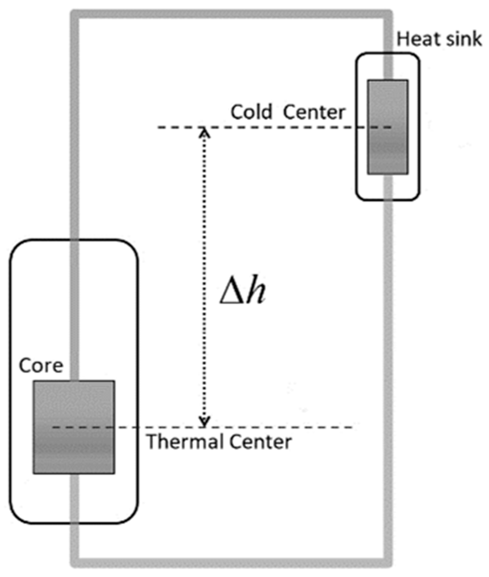
41]. The expression for buoyancy pressure due to the gradient of coolant density can be written as
Δ p b = β ρ g Δ T Δ h = β ˜ g Δ T Δ h
where β is the volumetric expansion coefficient, β ˜ = β ρ and Δ h is the height difference between the thermal and cold centers as shown in Figure 9.
In natural circulation, only one of three variables V c , q and Δ T is independent. For a given reactor power, the coolant velocity V c and rise in temperature Δ T can be estimated by using the energy and pressure balance equations. The coolant velocity can be eliminated from the pressure drop equation by employing the energy conservation equation as follows:
Δ p = 0.158 M D e 5 / 4 ρ 1 ( q A f n p i n n a s s m c p ) 7 / 4 ( Δ T ) 7 / 4 μ 1 / 4 L
By setting the total pressure drop equal to the buoyancy pressure, the velocity due to the natural circulation V c and coolant temperature rise Δ T are obtained as
Δ T = [ 0.158 M L ρ β ˜ g Δ h D e 5 / 4 ( q A f n p i n n a s s m c p ) 7 / 4 μ 1 / 4 ] 4 / 11
and
V c = q ρ A f n p i n n a s s m c p Δ T
On the other hand, with a predetermined coolant temperature rise, the height difference between the thermal and cold centers for natural circulation can be obtained as follows:
Δ h = 0.158 M L ρ β ˜ g Δ T 11 / 4 D e 5 / 4 ( q A f n p i n n a s s m c p ) 7 / 4 μ 1 / 4
Assuming that SPARK-NC has a 10 MWe power output and a predetermined coolant temperature rise of 120 °C, the corresponding height difference Δ h between the thermal and cold centers that is essential for heat removal from the core was estimated to be 1.42 m.

6. Load Following Analysis

There are three possible ways to regulate the reactor power to the target level: (1) by keeping the control assemblies fixed and changing the coolant inlet temperature, (2) moving the control assemblies and keeping the coolant inlet temperature constant, and (3) adjusting both the coolant inlet temperature and the position of the control assemblies. Since method (3) is complicated and makes it difficult to control the reactor, methods (1) and (2) were examined in this study. Both methods are discussed in detail in the subsequent sections.

6.1. Adjusting the Coolant Inlet Temperature

In this method for load following analysis of SPARK-NC, the quasi-static reactivity balance (QSRB) method established by Wade et al. at ANL [30] was implemented to calculate the required externally-imposed reactivity (by moving the control rods or adjustment of coolant inlet temperature) to change the reactor power to the desired level. The reactivity balance equation in the QSRB method is written as:
Δ ρ = ( P 1 ) A + ( P F 1 ) B + δ T in C + Δ ρ ext = 0
where P and F represents the normalized power and normalized flow, respectively, Δ ρ ext is the externally-imposed reactivity and δ T in is the change from typical coolant inlet temperature. A , B , and C are integral reactivity parameters, which are calculated from the reactivity feedback coefficients in Equations (9)–(11), Δ T C is the rise coolant temperature, and Δ T FC is the increase in the average fuel temperature relative to the average coolant temperature.
A = ( α D + α A ) Δ T FC
B = ( α D + α A + α C + 2 α R ) Δ T C / 2
C = α D + α A + α C + α R
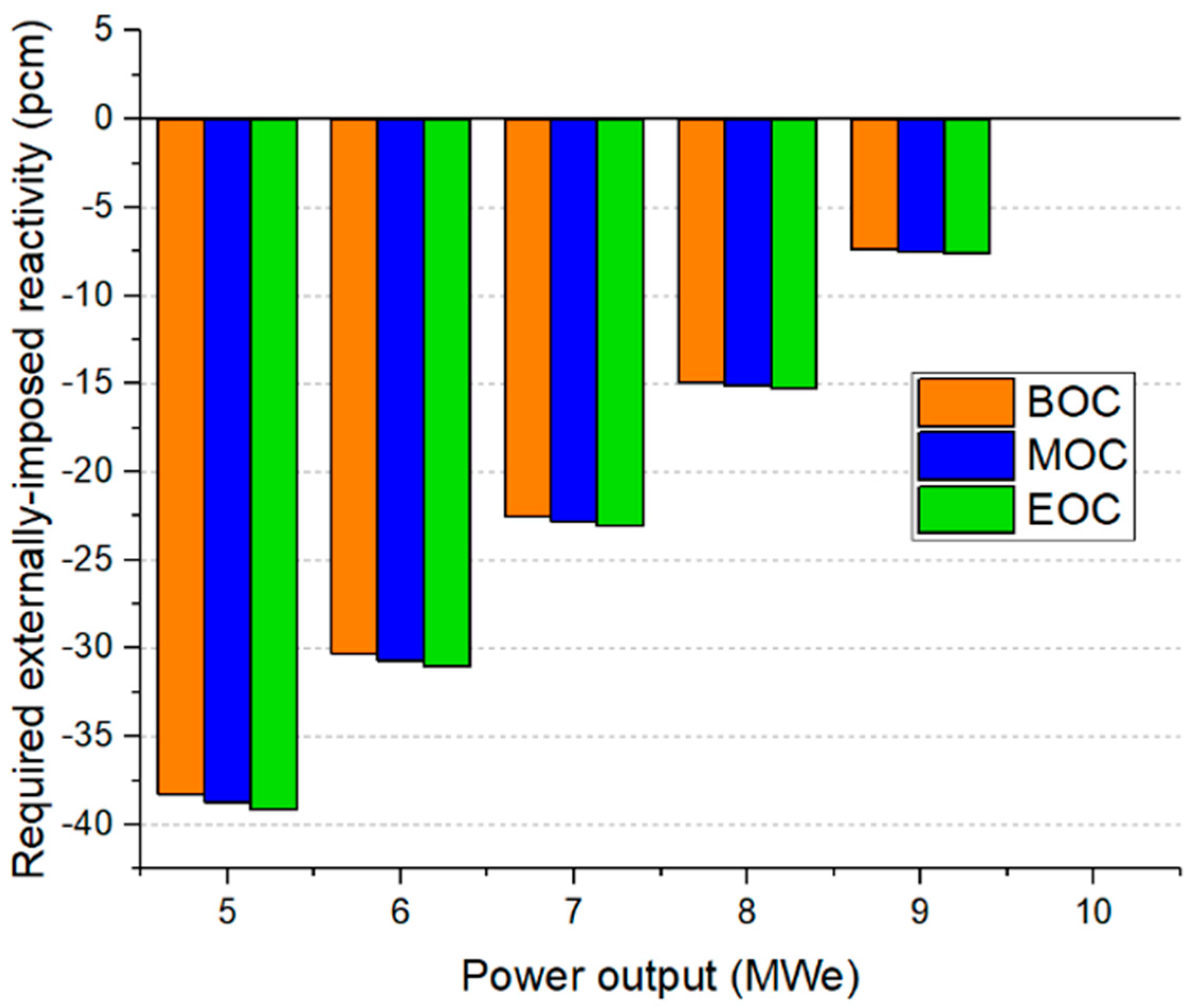
In the case of slow transients, in which the non-equilibrium energy in the fuel and delayed neutron imbalance can be prevented, Equation (8) illustrates the relationship among the externally controlled flow and temperature parameters of the coolant, the externally imposed reactivity, and the new adjusted power level of the reactor core. The power level ascends or descends through the core power coefficients in order to compensate for any change in the reactivity. The reactivity balance equation can be correlated with the energy conservation and pressure drop equation to estimate externally-imposed reactivity (through the adjustment of the coolant inlet temperature or by movement of the control assemblies) required to attain the desired power level. The nominal power output is set to 10 MWe as the basis of the operation and the essential externally-imposed reactivity for different power outputs at various time points of the fuel cycle is estimated using method (1), as shown in 
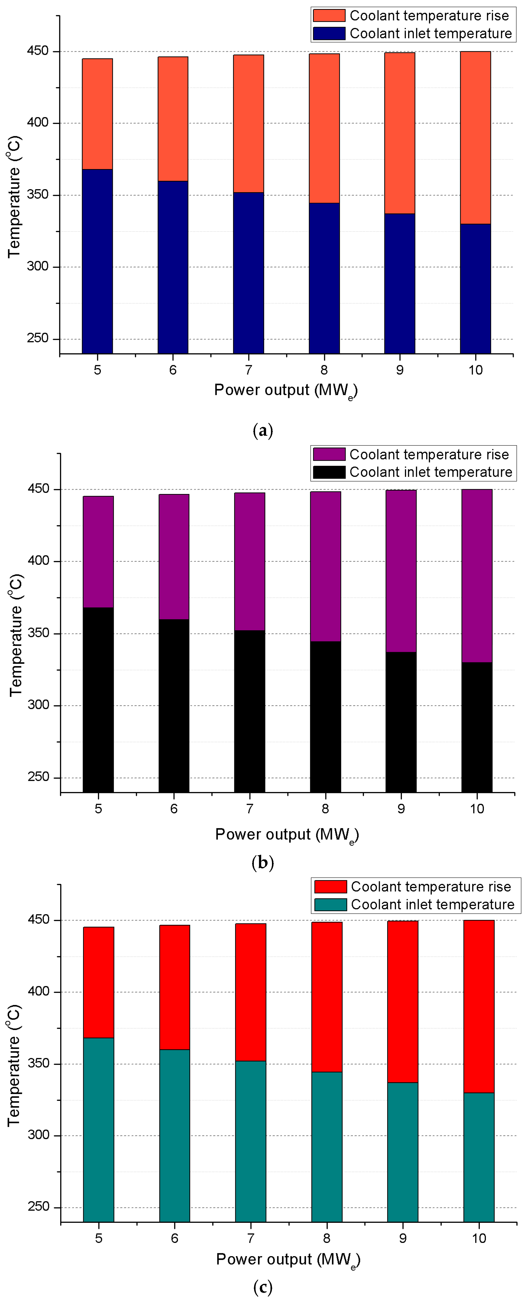
Figure 10. The inlet coolant temperature and the rise in coolant temperature at various power outputs and at different time points in the fuel cycle are plotted in Figure 11.
It is clear that the power output can be changed from 10 MWe to 5 MWe at BOC, MOC or EOC by raising the coolant inlet temperature by around 37 °C, while the corresponding coolant outlet temperature is approximately 445 °C. When the power output is changed from 5 MWe to 9 MWe, the range in the variation of the coolant inlet and outlet temperatures overlaps with the range of the nominal coolant inlet and outlet temperatures in the basic operational case (10 MWe) throughout the entire fuel cycle, which indicates the viability of load following operation by adjusting the coolant inlet temperature.

6.2. Adjusting the Position of Control Assemblies

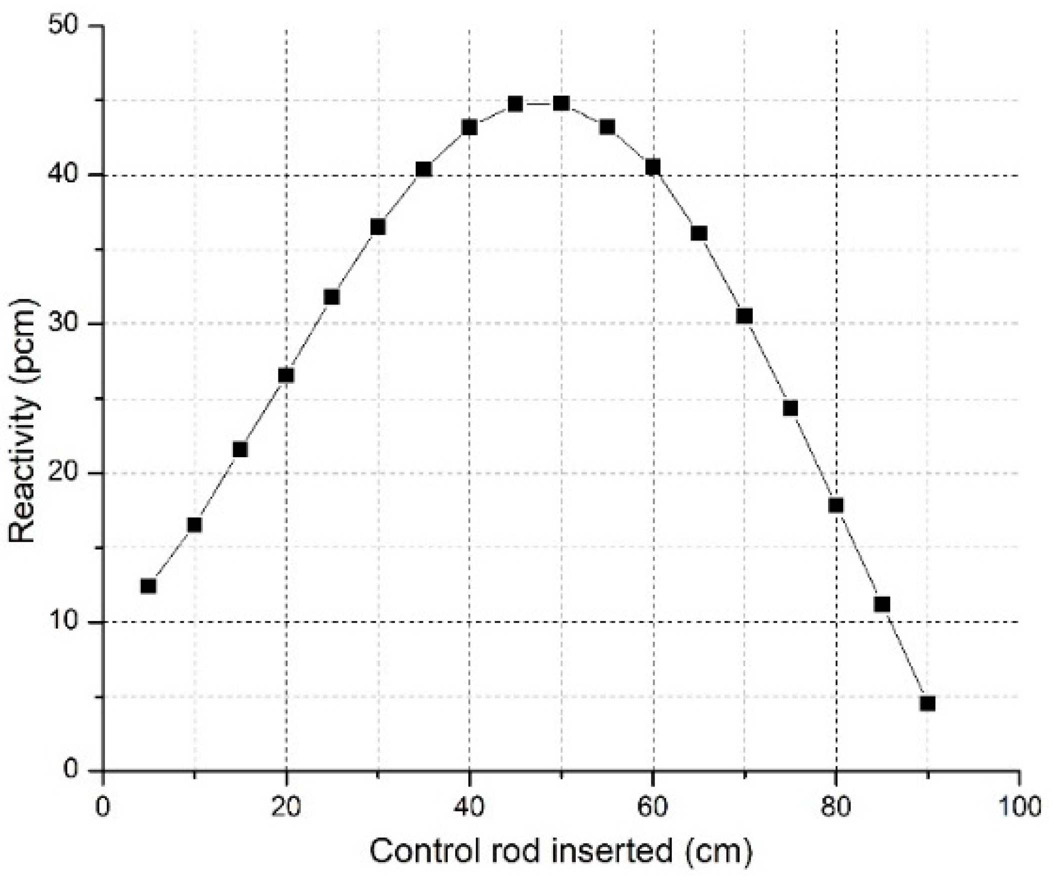
In the second method, manipulation of the power was achieved by moving the secondary control assemblies, which act as power regulating assemblies while keeping the inlet temperature constant. The reactivity insertion during load following and the resulting effect on the power distribution and thermal hydraulic parameters were investigated using DAISY code. Control assemblies with relatively low rod worth were chosen to avoid deformation in the power shape and degrading the neutron economy. The differential reactivity worth of secondary control assemblies at BOC is given in Figure 12.
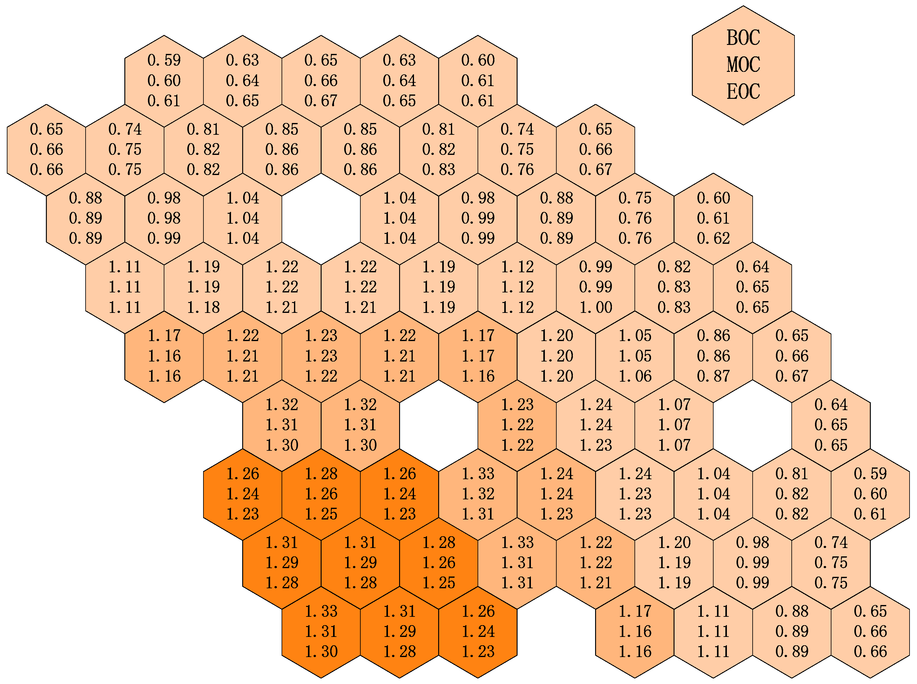
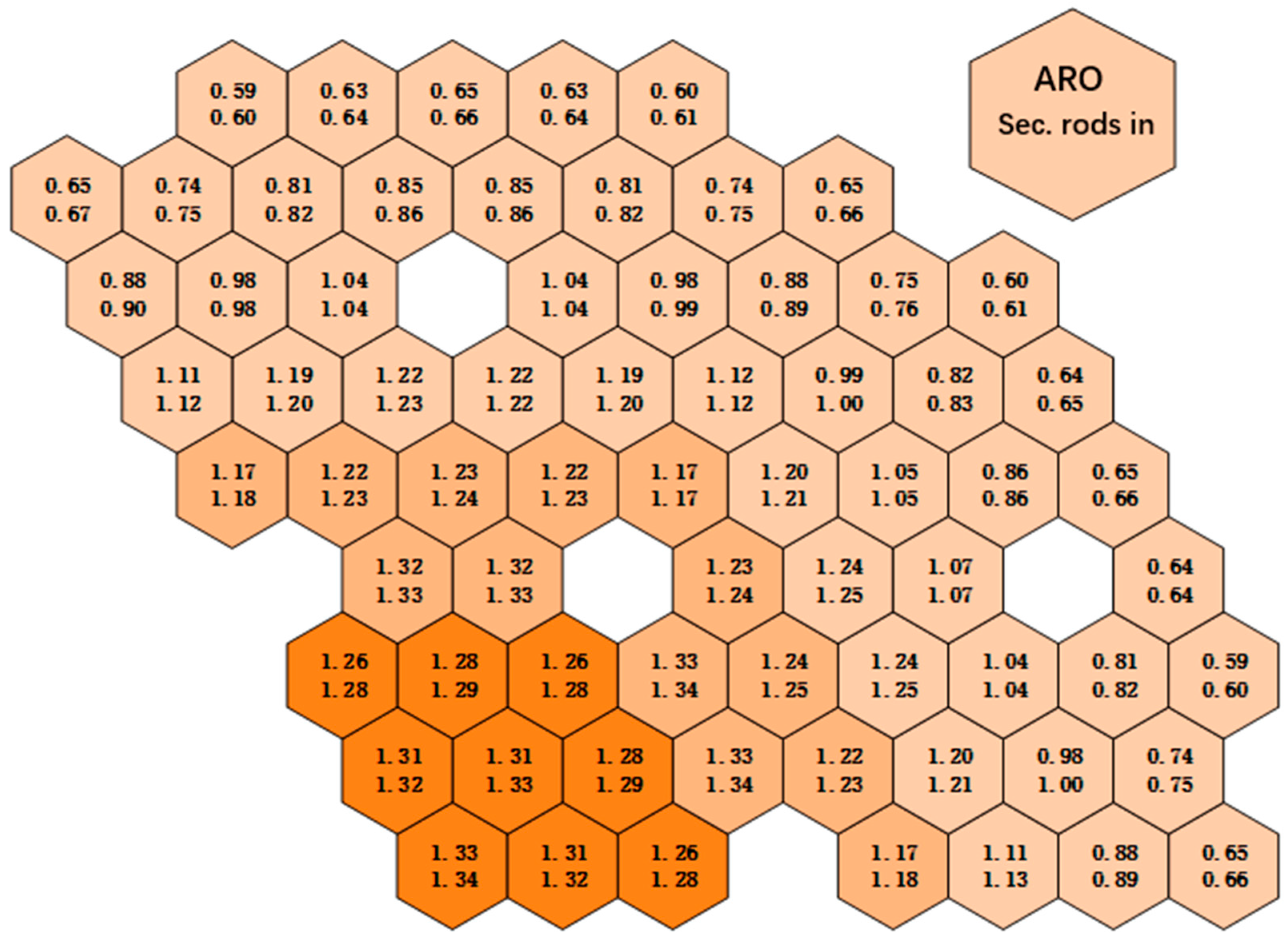
The change in the power distribution with the insertion of power regulating rods was studied at BOC. The radial power distribution was not deformed significantly and the peaking factor of the hottest assembly changed from 1.33 to 1.34 at BOC as shown in 
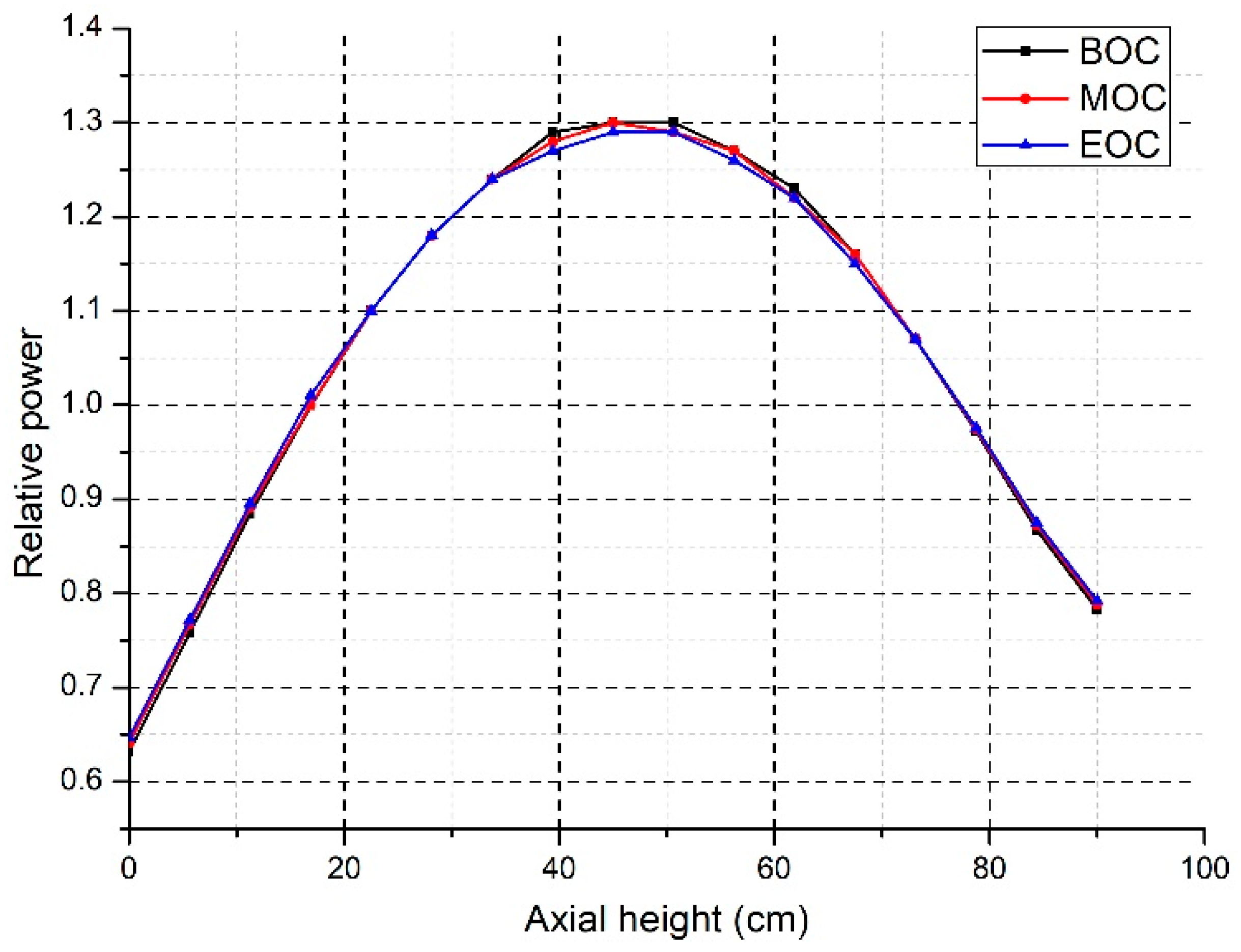
Figure 13. The axial power profile in central and peripheral regions changed slightly when the low worth control rods were moved. The axial peaking factors of the lower half of the fuel assemblies bulged out slightly as shown in Figure 14.
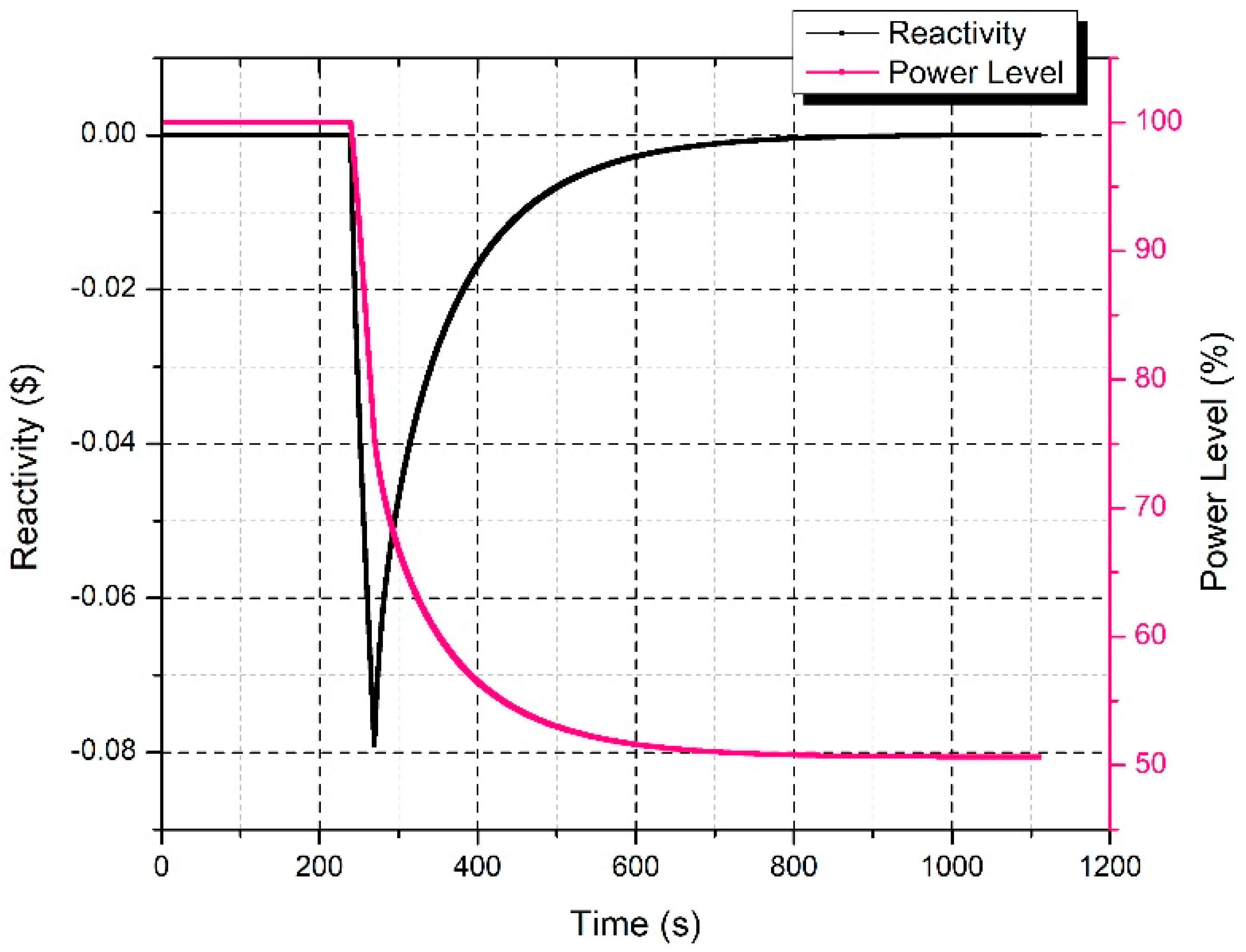
To lower the reactor power level by 50%, $0.08 negative reactivity was inserted for 15 sec as shown in 
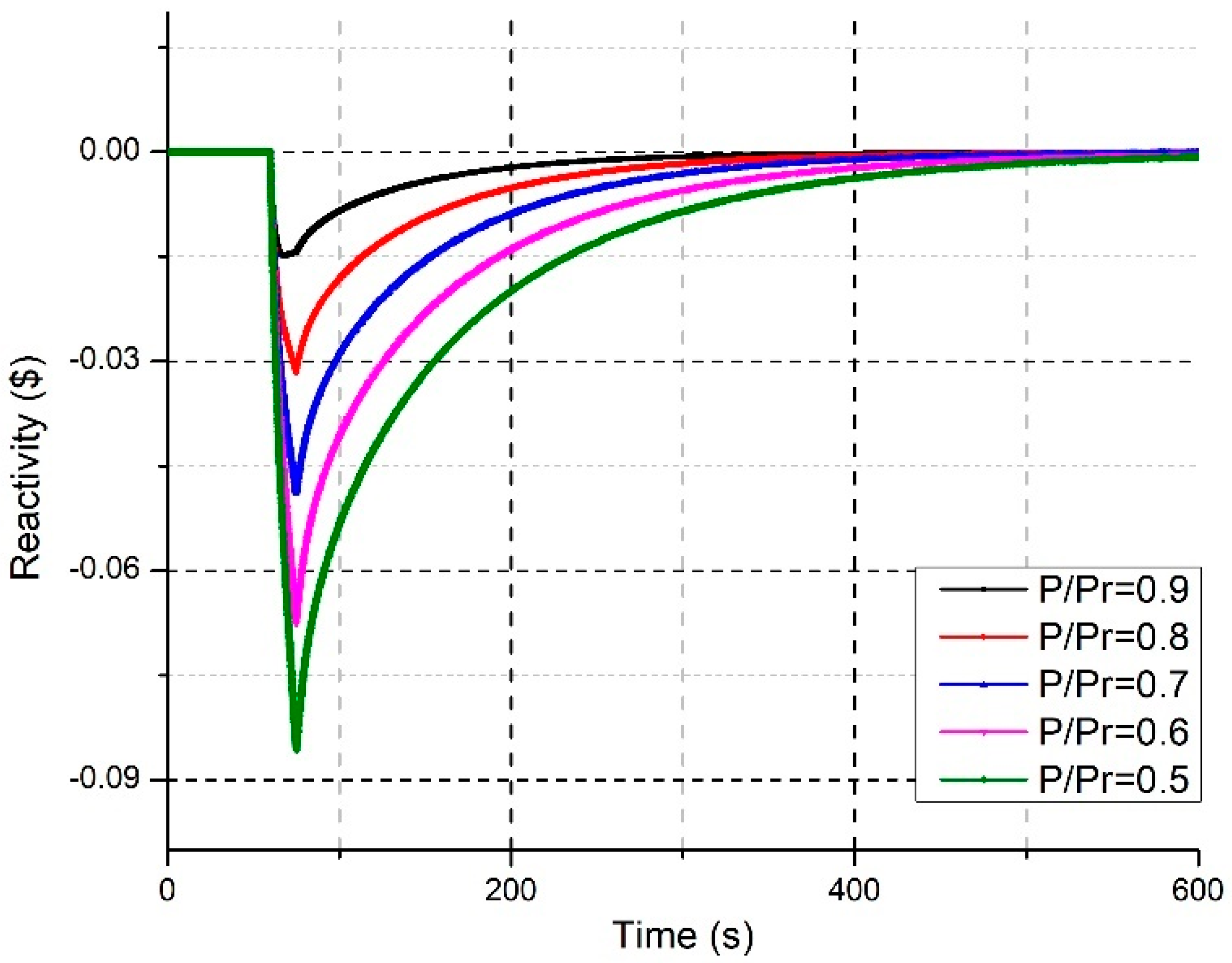
Figure 15. The negative reactivity coefficients start working and begin to raise the reactivity until it reaches a steady state. while the power level reaches its desired level in 5 min and remains unchanged due to the reactivity coefficients and neutronics parameters. The power level was also reduced in 10% steps between the rated power of 10 MWe and 5 MWe by inserting different reactivities with the regulating assemblies as shown in 
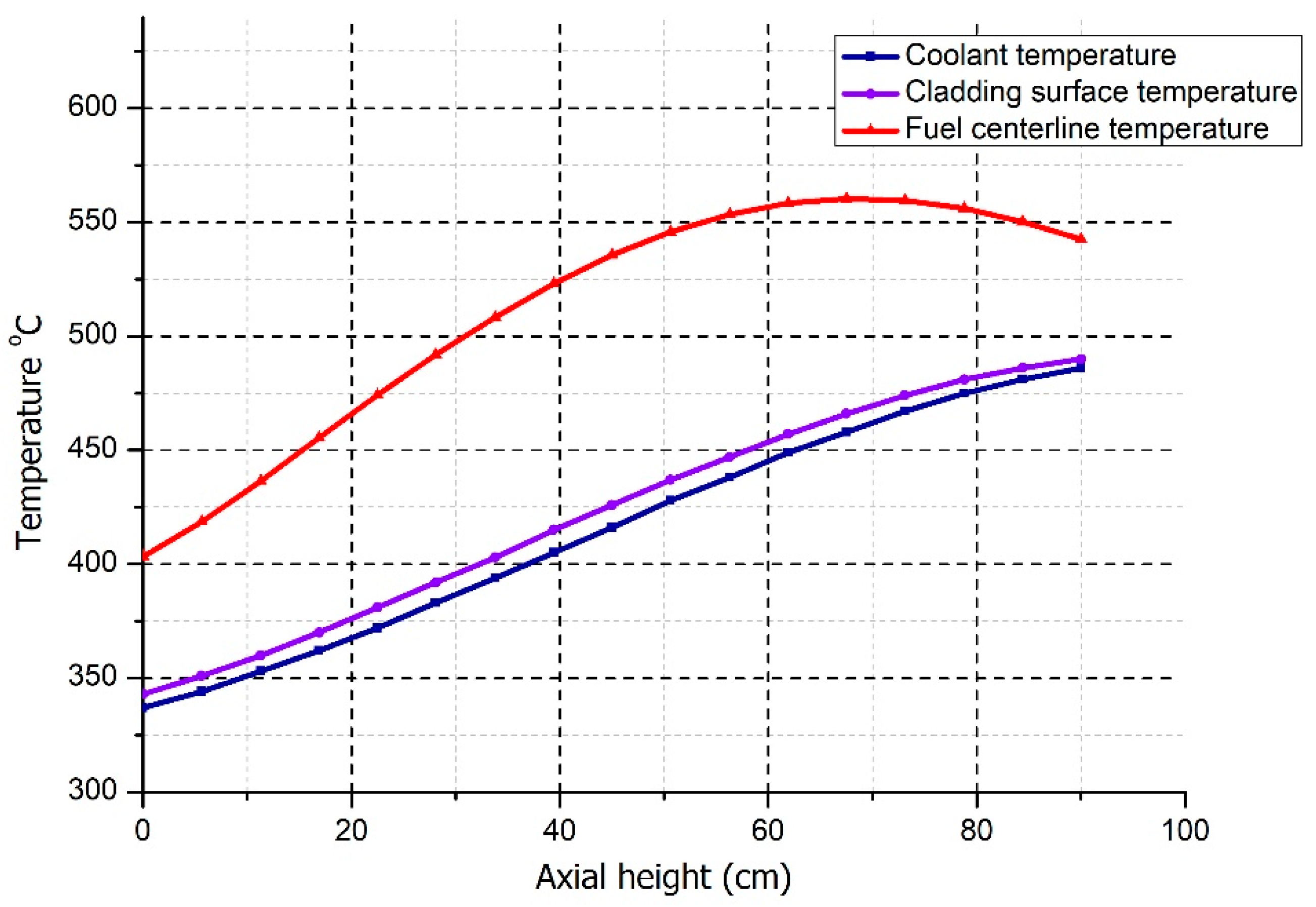
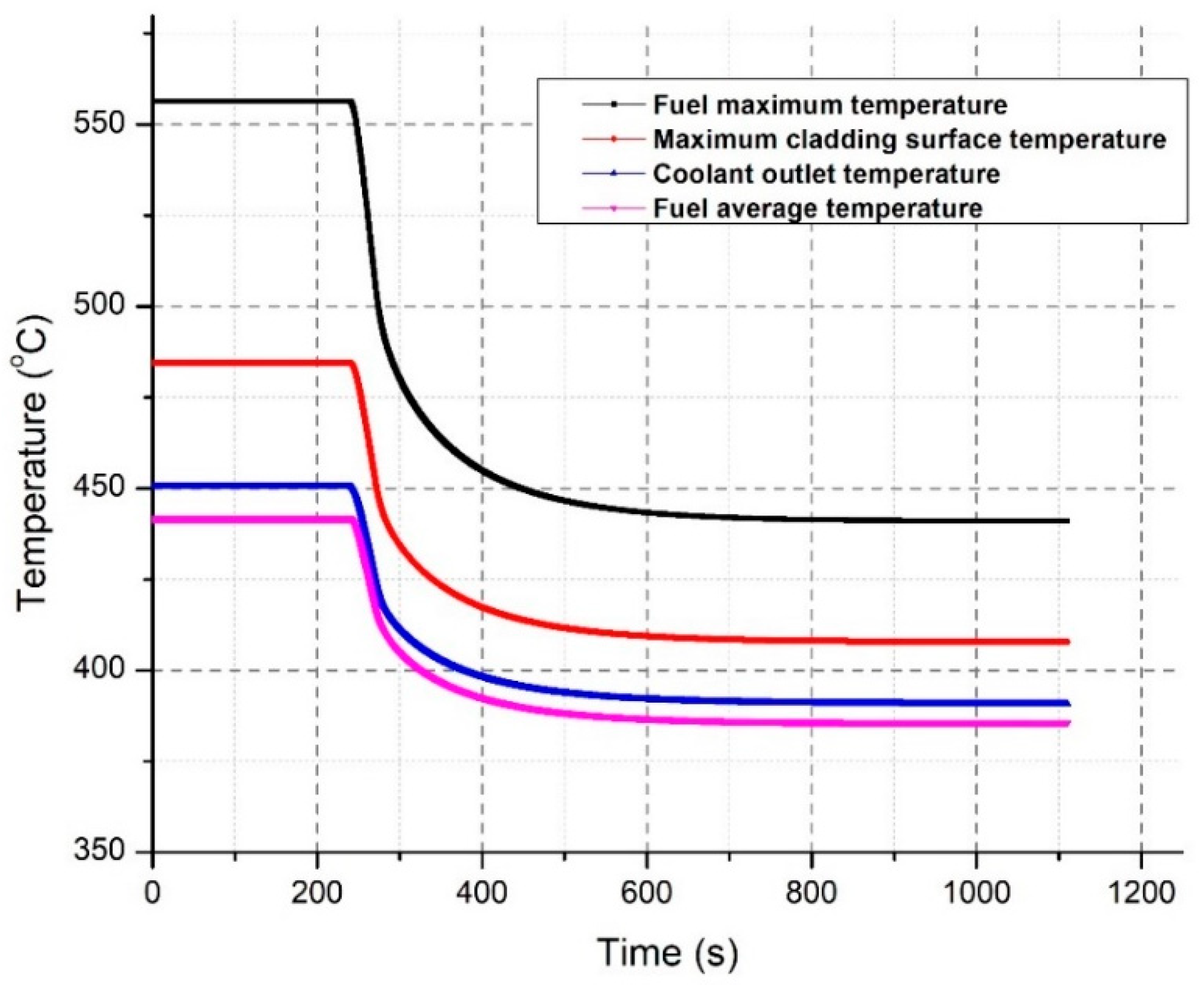
Figure 16. The temperatures are proportional to the power, when the power is decreased the temperature of the fuel and coolant also decreases. The change in temperature of fuel and coolant corresponding to a 50% drop in reactor power is shown in Figure 17.
The initial values of the coolant outlet temperature, maximum cladding surface temperature, fuel maximum temperature and fuel average temperature were 450 °C, 484.4 °C, 556.5 °C and 441.7 °C, respectively. After the regulating rods were inserted, these values started to decrease and reached constant values of 390.7 °C, 407.8 °C, 441.1 °C, 385.7 °C, respectively. In fast spectrum reactors, the reactivity feedback coefficients are very small. Therefore, for the desired power output range, the adjustment range of the externally-imposed reactivity is quite narrow. This presents a challenge in fine-tuning the position of the control assemblies to provide small-scale reactivity. The adjustment of coolant inlet temperature is a reasonably easy task that involves simply altering the mass flow rate of water into the steam generator. Hence, method (1), which attains the desired power level through regulating the coolant inlet temperature is preferred.

7. Conclusions

In the present study, a conceptual design for a small lead-bismuth-cooled core fast reactor, SPARK-NC with natural circulation and load following was proposed for the purpose of providing remote power supply. The nominal power output was set to 10 MWe, and can be adjusted from 5 MWe to 10 MWe throughout the entire core lifetime. The core neutronics and thermal-hydraulics design calculations were performed using the SARAX code and the natural circulation capability of SPARK-NC was investigated by employing the energy conservation equation, pressure drop equation and quasi-static reactivity balance equation. In order to flatten the radial power distribution, three radial zones were constructed by using different fuel enrichments and fuel pin diameters. To ensure an adequate shutdown margin, two independent systems, i.e., a control system and a scram system, were introduced in the core. The control assemblies are further classified into two types: primary control assemblies used for reactivity control and power flattening and secondary control assemblies (with relatively smaller reactivity worth) used for power regulation. The tungsten ballast coated with B4C was used in the scram assemblies to counteract the buoyancy of the high-density coolant. The targeted fuel cycle length of 8 EFPYs was fulfilled with a compact core design, and the neutronics and thermal-hydraulics parameters were below the design constraints throughout the entire fuel cycle. Two methods for the load following capability (adjusting the coolant inlet temperature and the movement of secondary control assemblies) of SPARK-NC were assessed. By comparing various methods for adjusting the reactor power output, we found that adjusting the coolant inlet temperature was the most viable, easy to implement and favored for the load following operation.
The reliability of fuel and structural components in load following reactors is very important for maneuverability. The alteration in power with fluctuating demand produces variations in the coolant temperature, which consequently leads to periodic changes in the mechanical load of some reactor components. For large temperature gradient, this may create localized structural impairment (fatigue) in the reactor components. Moreover, the fuel performance could be constrained by the deterioration in the fuel cladding due to the pellet-cladding interaction (PCI), stress corrosion cracking and various other processes.
In future work, the mechanical characteristics and integrity of fuel and structural components need to be assessed during the load following operation of SPARK-NC. This examination should include the fatigue, tensile and fractural toughness of fuel and structural parts at high temperature, and also the study of long-term corrosion and irradiation effects.

Author Contributions

Conceptualization, L.C.; methodology, S.Z.; software, M.H., Y.S.; formal analysis, M.H.; investigation, R.C.; resources, R.M.; data curation, M.H.; writing—original draft preparation, M.H., S.Z.; writing—review and editing, S.Z., L.C.; supervision, L.C.; project administration, L.C.; funding acquisition, L.C. All authors have read and agreed to the published version of the manuscript.

Funding

This work was supported by National Key Research and Development Program of China (No. 2019YFB1901102) and the National Natural Science Foundation of China (No. 11735011).

Conflicts of Interest

The authors declare no conflict of interest.

References

  1. Kuznetsov, V. Design Status and Applications of Small Reactors Without On-Site Refuelling. In Proceedings of the 14th International Conference on Nuclear Engineering, Miami, FL, USA, 17–20 July 2006; pp. 565–573. [Google Scholar]
  2. Waddington, G. Small Modular Reactors (SMR) Feasibility Study; National Nuclear Laboratory: Sellafield, UK, 2014. [Google Scholar]
  3. Choe, J.; Zheng, Y.; Lee, D.; Shin, H.C. Boron-free small modular pressurized water reactor design with new burnable absorber. Int. J. Energy Res. 2016, 40, 2128–2135. [Google Scholar] [CrossRef]
  4. Ingersoll, D.T.; Houghton, Z.J.; Bromm, R.; Desportes, C. NuScale small modular reactor for Co-generation of electricity and water. Desalination 2014, 340, 84–93. [Google Scholar] [CrossRef]
  5. Zhu, D.; Xiang, Q.; Zhang, M.; Deng, C.; Deng, J.; Jiang, G.; Yu, H. Evaluation of in-vessel corium retention margin for small modular reactor ACP100. Ann. Nucl. Energy 2016, 94, 684–690. [Google Scholar] [CrossRef]
  6. Odeh, F.Y.; Yang, W.S. Core design optimization and analysis of the Purdue Novel Modular Reactor (NMR-50). Ann. Nucl. Energy 2016, 94, 288–299. [Google Scholar] [CrossRef] [Green Version]
  7. Bortot, S.; Moisseytsev, A.; Sienicki, J.; Artioli, C. Core design investigation for a SUPERSTAR small modular lead-cooled fast reactor demonstrator. Nucl. Eng. Des. 2011, 241, 3021–3031. [Google Scholar] [CrossRef]
  8. Hartanto, D.; Kim, C.; Kim, Y. A comparative physics study for an innovative sodium-cooled fast reactor (iSFR). Int. J. Energy Res. 2018, 42, 151–162. [Google Scholar] [CrossRef]
  9. Sienicki, J.J.; Petkov, P.V. Passive safety of the STAR-LM HLMC natural convection reactor. In Proceedings of the 10th International Conference on Nuclear Engineering, Arlington, VA, USA, 14–18 April 2002; pp. 659–666. [Google Scholar]
  10. Smith, C.F.; Halsey, W.G.; Brown, N.W.; Sienicki, J.J.; Moisseytsev, A.; Wade, D.C. SSTAR: The US lead-cooled fast reactor (LFR). J. Nucl. Mater. 2008, 376, 255–259. [Google Scholar] [CrossRef] [Green Version]
  11. Wade, D.; Doctor, R.; Peddicord, K. STAR-H2: The secure transportable autonomous reactor for hydrogen production and desalinization. In Proceedings of the 10th International Conference on Nuclear Engineering, Arlington, VA, USA, 14–18 April 2002; pp. 205–214. [Google Scholar]
  12. Zhou, S.; Chen, R.; Shao, Y.; Cao, L.; Bai, B.; Wu, H. Conceptual core design study of an innovative small transportable lead-bismuth cooled fast reactor (SPARK) for remote power supply. Int. J. Energy Res. 2018, 42, 3672–3687. [Google Scholar] [CrossRef]
  13. Zrodnikov, A.V.; Toshinsky, G.I.; Komlev, O.G.; Stepanov, V.S.; Klimov, N.N. SVBR-100 module-type fast reactor of the IV generation for regional power industry. J. Nucl. Mater. 2011, 415, 237–244. [Google Scholar] [CrossRef]
  14. Kim, S.G.; Yu, H.; Moon, J.; Baik, S.; Kim, Y.; Jeong, Y.H.; Lee, J.I. A concept design of supercritical CO2 cooled SMR operating at isolated microgrid region. Int. J. Energy Res. 2017, 41, 512–525. [Google Scholar] [CrossRef]
  15. Kim, Y.; Hartanto, D.; Yu, H. Neutronics optimization and characterization of a long-life SCO2-cooled micro modular reactor. Int. J. Energy Res. 2017, 41, 976–984. [Google Scholar] [CrossRef]
  16. Brown, N.R.; Betzler, B.R.; Carbajo, J.J.; Wysocki, A.J.; Greenwood, M.S.; Gentry, C.; Qualls, A.L. Preconceptual design of a fluoride high temperature salt-cooled engineering demonstration reactor: Core design and safety analysis. Ann. Nucl. Energy 2017, 103, 49–59. [Google Scholar] [CrossRef] [Green Version]
  17. Zhou, S.; Cao, L.; Wu, H.; Bai, B.; Lei, C.; Zhang, Y. SPARK-LS: A novel design of a compact liquid chloride salt cooled fast reactor based on tube-in-duct fuel concept. Ann. Nucl. Energy 2019, 128, 248–255. [Google Scholar] [CrossRef]
  18. Van den Bosch, J.; Hosemann, P.; Almazouzi, A.; Maloy, S. Liquid metal embrittlement of silicon enriched steel for nuclear applications. J. Nucl. Mater. 2010, 398, 116–121. [Google Scholar] [CrossRef]
  19. Weisenburger, A.; Schroer, C.; Jianu, A.; Heinzel, A.; Konys, J.; Steiner, H.; Müller, G.; Fazio, C.; Gessi, A.; Babayan, S. Long term corrosion on T91 and AISI1 316L steel in flowing lead alloy and corrosion protection barrier development: Experiments and models. J. Nucl. Mater. 2011, 415, 260–269. [Google Scholar] [CrossRef]
  20. Lambrinou, K.; Koch, V.; Coen, G.; Van den Bosch, J.; Schroer, C. Corrosion scales on various steels after exposure to liquid lead–bismuth eutectic. J. Nucl. Mater. 2014, 450, 244–255. [Google Scholar] [CrossRef]
  21. Schroer, C.; Voß, Z.; Wedemeyer, O.; Novotny, J.; Konys, J. Oxidation of steel T91 in flowing lead–bismuth eutectic (LBE) at 550 °C. J. Nucl. Mater. 2006, 356, 189–197. [Google Scholar] [CrossRef]
  22. Takahashi, M.; Igashira, M.; Obara, T.; Sekimoto, H.; Kikuchi, K.; Aoto, K.; Kitano, T. Studies on Materials for Heavy-Liquid-Metal-Cooled Reactors in Japan. In Proceedings of the 10th International Conference on Nuclear Engineering, Arlington, VA, USA, 14–18 April 2002; pp. 549–559. [Google Scholar]
  23. Zrodnikov, A.; Chitaykin, V.; Gromov, B.; Grigoryv, O.; Dedoul, A.; Toshinsky, G.; Dragunov, Y.G.; Stepanov, V. Use of Russian Technology of Ship Reactors With Lead-Bismuth Coolant in Nuclear Power, Proceedings of the Advisory Group Meeting on Small Power and Heat Generation Systems on the Basis of Propulsion and Innovative Reactor Technologie, Obninsk, Russia, 20–24 July 1998; International Atomic Energy Agency: Vienna, Austria, 2000. [Google Scholar]
  24. Zrodnikov, A.; Toshinsky, G.; Dragunov, U.; Stepanov, V.; Klimov, N.; Kopytov, I.; Krushelnitsky, V.; Yermakov, N.; Kornienko, A. Lead-Bismuth Reactor Technology Conversion: From Nuclear Submarine Reactors to Power Reactors and Ways of Increasing the Investment Attractiveness of Nuclear Power Based on Fast Reactors, Proceedings of the International Conference on Fifty Years of Nuclear Power—The Next Fifty Years, Moscow, Russia, 27 June–2 July 2004; International Atomic Energy Agency: Vienna, Austria, 2004. [Google Scholar]
  25. Zrodnikov, A.; Toshinsky, G.; Komlev, O.; Dragunov, Y.G.; Stepanov, V.; Klimov, N.; Kopytov, I.; Krushelnitsky, V. Nuclear power development in market conditions with use of multi-purpose modular fast reactors SVBR-75/100. Nucl. Eng. Des. 2006, 236, 1490–1502. [Google Scholar] [CrossRef]
  26. Greenspan, E.; Hong, S.G.; Lee, K.B.; Monti, L.; Okawa, T.; Susplugas, A.; Fratoni, M.; Kim, L.; Mattafirri, S.; Petroski, R. Innovations in the ENHS reactor design and fuel cycle. Prog. Nucl. Energy 2008, 50, 129–139. [Google Scholar] [CrossRef]
  27. Sienicki, J.J.; Spencer, B.W. Power optimization in the Star-LM modular natural convection reactor system. In Proceedings of the 10th International Conference on Nuclear Engineering, Arlington, VA, USA, 14–18 April 2002; pp. 685–690. [Google Scholar]
  28. Chen, H.; Chen, Z.; Chen, C.; Zhang, X.; Zhang, H.; Zhao, P.; Shi, K.; Li, S.; Feng, J.; Zeng, Q. Conceptual design of a small modular natural circulation lead cooled fast reactor SNCLFR-100. Int. J. Hydrog. Energy 2016, 41, 7158–7168. [Google Scholar] [CrossRef]
  29. Sienicki, J.; Moisseytsev, A.; Yang, W.; Wade, D.; Nikiforova, A.; Hanania, P.; Ryu, H.; Kulesza, K.; Kim, S.; Halsey, W. Status Report on the Small Secure Transportable Autonomous Reactor (SSTAR)/Lead-Cooled Fast Reactor (LFR) and Supporting Research and Development; Argonne National Lab. (ANL): Argonne, IL, USA, 2008. [Google Scholar]
  30. Wade, D.C.; Chang, Y.I. The Integral Fast Reactor (IFR) Concept: Physics of Operation and Safety; Societe Francaise d’Energie Nucleaire: Paris, France, 1987. [Google Scholar]
  31. Hosemann, P.; Frazer, D.; Stergar, E.; Lambrinou, K. Twin boundary-accelerated ferritization of austenitic stainless steels in liquid lead–bismuth eutectic. Scr. Mater. 2016, 118, 37–40. [Google Scholar] [CrossRef] [Green Version]
  32. Li, N. Lead-alloy coolant technology and materials—Technology readiness level evaluation. Prog. Nucl. Energy 2008, 50, 140–151. [Google Scholar] [CrossRef]
  33. Waltar, A.E.; Todd, D.R.; Tsvetkov, P.V. Fast Spectrum Reactors; Springer: New York, NY, USA, 2011. [Google Scholar]
  34. Zheng, Y.; Du, X.; Xu, Z.; Zhou, S.; Liu, Y.; Wan, C.; Xu, L. SARAX: A new code for fast reactor analysis part I: Methods. Nucl. Eng. Des. 2018, 340, 421–430. [Google Scholar] [CrossRef]
  35. Zhou, S.; Wu, H.; Cao, L.; Zheng, Y.; Huang, K.; He, M.; Li, X. LAVENDER: A steady-state core analysis code for design studies of accelerator driven subcritical reactors. Nucl. Eng. Des. 2014, 278, 434–444. [Google Scholar] [CrossRef]
  36. He, M.; Wu, H.; Cao, L.; Zheng, Y.; Zhou, S. Time-Dependent, Three Dimensional Nodal Transport Code Development Based on Unstructured Mesh. In Proceedings of the 22nd International Conference on Nuclear Engineering, Prague, Czech Republic, 7–11 July 2014. [Google Scholar]
  37. Du, X.; Cao, L.; Zheng, Y.; Wu, H. Developments of the sodium fast reactor analysis code SARAX: Methods and verification. In Proceedings of the International Conference on Mathematics & Computational Methods Applied to Nuclear Science & Engineering, Jeju, Korea, 16–20 April 2017. [Google Scholar]
  38. Xu, L.; Cao, L.; Zheng, Y.; Wu, H. Development of a new parallel SN code for neutron-photon transport calculation in 3-D cylindrical geometry. Prog. Nucl. Energy 2017, 94, 1–21. [Google Scholar] [CrossRef]
  39. Zheng, Y.; Xiao, Y.; Wu, H. Application of the virtual density theory in fast reactor analysis based on the neutron transport calculation. Nucl. Eng. Des. 2017, 320, 200–206. [Google Scholar] [CrossRef]
  40. Zheng, Y.; Qiao, L.; Zhai, Z.a.; Du, X.; Xu, Z. SARAX: A new code for fast reactor analysis part II: Verification, validation and uncertainty quantification. Nucl. Eng. Des. 2018, 331, 41–53. [Google Scholar] [CrossRef]
  41. Davis, C.; Herring, S.; MacDonald, P.; McCarthy, K.; Shah, V.; Weaver, K.; Buongiorno, J.; Ballinger, R.; Doyoung, K.; Driscoll, M.; et al. Design of an Actinide Burning, Lead-Bismuth Cooled Reactor That Produces Low Cost Electricity; Idaho National Engineering and Environmental Lab.: Idaho Falls, ID, USA, 1999; 77p. [Google Scholar]
Figure 1. Detailed radial and axial configuration of the core. (a) Radial configuration of the core, and (b) axial configuration of the core.
Energies 13 05410 g001
Figure 2. Fuel assembly configuration.
Energies 13 05410 g002
Figure 3. Control assembly configuration.
Energies 13 05410 g003
Figure 4. Scram assembly configuration.
Energies 13 05410 g004
Figure 5. Evolution of keff with time for the reactor core design.
Energies 13 05410 g005
Figure 6. Comparison of power peaking factors at BOC, MOC and EOC for ARO core.
Energies 13 05410 g006
Figure 7. Axial power distribution of the ARO core from bottom to top, at BOC, MOC and EOC.
Energies 13 05410 g007
Figure 8. Axial temperature profile of the hottest assembly at BOC.
Energies 13 05410 g008
Figure 9. Illustrative diagram of natural circulation in the primary loop.
Energies 13 05410 g009
Figure 10. Externally-imposed reactivity required for different power output.
Energies 13 05410 g010
Figure 11. Coolant inlet temperature and coolant temperature rise for different power output. (a) BOC (b) MOC (c) EOC.
Energies 13 05410 g011
Figure 12. Differential control rod worth of secondary control assemblies at BOC.
Energies 13 05410 g012
Figure 13. Change in radial power profile after the insertion of the regulating rods at BOC.
Energies 13 05410 g013
Figure 14. Change in axial power profile near the secondary assemblies when fully inserted at BOC.
Energies 13 05410 g014
Figure 15. Reactivity insertion by regulating rods for a 50% power decrease.
Energies 13 05410 g015
Figure 16. Power level operation for different power levels.
Energies 13 05410 g016
Figure 17. Change in temperatures for a 50% power decrease.
Energies 13 05410 g017
Table 1. Design parameters of the core.
ItemSpecification
Reactor power, MWth30
Fuel cycle length, EFPY8
Capacity factor0.9
Equivalent core radius, cm110.4
Reactor vessel diameter (in/out), cm232/236
Total core height, cm215
Active core height, cm90
Assembly pitch, cm10.8
Fuel assembly number (in/mid/out)19/36/132
Control/scram assembly number9/3
Reflector/shielding assembly number114/66
Table 2. Design parameters of the fuel assemblies.
ItemSpecification
Fuel composition form (In/mid/out), % enriched UO217.00/17.00/19.75
Cladding materialT91
Gap materialHe
Assembly flat to flat distance, cm10.6
Assembly wrapper thickness, cm0.3
Number of fuel pins per assembly61
Fuel pin diameter (In/mid/out), cm0.96/1.0/1.0
Pitch /diameter ratio (In/mid/out)1.28/1.24/1.24
Cladding thickness, cm0.04
Gap thickness, cm0.015
Active fuel height, cm90
Gas plenum height, cm75
Upper reflector height, cm15
Lower reflector height, cm25
Top/bottom end cap height, cm5
Table 3. Design parameters of the control and scram assemblies.
ItemSpecification
Absorber material (scram/primary/secondary), % 10B enriched B4C40/19.99/19.99
Absorber rod radius, (scram/primary/secondary), cm0.90/0.90/0.60
CladdingT91
Absorber rod number19
Absorber rod pitch, cm2.01
Boron carbide coating thickness (scram assembly), cm0.25
Cladding thickness, cm0.04
Gap thickness, cm0.02
Assembly flat to flat distance, cm10.6
Outer wrapper thickness, cm0.3
Annulus thickness, cm0.2
Inner wrapper thickness, cm0.2
Table 4. Performance parameters of the reactor core design.
ItemSpecification
Coolant temperature (in/out), °C330/450
Coolant mass flow rate, kg·s−11746
Coolant flow velocity, m·s−10.31
Heavy metal inventory at BOC, kg5745
Reactor core weight, metric ton64.9
Average power density (of fuel volume inside cladding), W/cm3111.3
Peak power density (of fuel volume inside cladding) at BOC and EOC, W/cm3189.6/183.5
Peak fast fluence (> 0.1 MeV) in the core at EOC, n/cm23.27 × 1021
Peak coolant temperature in the core at BOC and EOC, °C487/486
Peak cladding surface temperature in the core at BOC and EOC, °C491/489
Peak fuel centerline temperature in the core at BOC and EOC, °C560/557
Table 5. Reactivity feedback coefficients and kinetics parameters.
CoefficientBOCMOCEOC
αD, pcm/°C−0.831−0.849−0.869
αC, pcm/°C−0.655−0.653−0.650
αA, pcm/°C−0.157−0.160−0.164
αR, pcm/°C−0.648−0.658−0.670
βeff, pcm709.1695.3679.7
λ, μs0.4560.4650.475
CVR in the active core, pcm−2273.5−2208.2−2130.7
CVR in the whole core, pcm−10,169.0−101,966.5−10,222.1
Table 6. Reactivity worth of control and scram systems at BOC.
Reactivity, $Control SystemScram System
Temperature defect:
Full power to hot standby0.320.32
Hot standby to refueling0.360.00
Overpower0.160.16
Reactivity fault1.572.04
Fuel cycle excess reactivity3.290.00
Uncertainties1.200.00
Maximum requirement6.892.51
Reactivity aviailable10.156.11
Shutdown margin3.263.60
Table 7. Contributions to the temperature defect at BOC.
Contribution, $Full Power to Hot StandbyHot Standby (330 °C) to Refueling (230 °C)
Doppler effect0.1370.151
Axial fuel expansion0.0240.022
Radial core expansion0.0990.092
Coolant density0.0550.092
Total0.3160.357
Publisher’s Note: MDPI stays neutral with regard to jurisdictional claims in published maps and institutional affiliations.

