Article

Neutron Activation of Structural Materials of a Dry Storage System for Spent Nuclear Fuel and Implications for Radioactive Waste Management

Department of Nuclear Engineering, Kyung Hee University, 1732 Deokyoung-daero, Giheung-gu, Yongin-si, Gyeonggi-do 17104, Korea
*
Author to whom correspondence should be addressed.
Energies 2020, 13(20), 5325; https://doi.org/10.3390/en13205325
Submission received: 31 August 2020 / Revised: 30 September 2020 / Accepted: 5 October 2020 / Published: 13 October 2020
(This article belongs to the Special Issue Nulcear Energy and Technology)

Abstract

:
In order to estimate the radiological characteristics of disused dry storage systems for spent nuclear fuel, a stepwise framework to calculate neutron sources (ORIGEN-ARP), incident neutron flux and reaction rate (MCNPX), effective cross-section (hand calculation), and residual activity (ORIGEN-2) was established. Applicability of the framework was demonstrated by comparing the residual activity of a commercialized storage system, HI-STORM 100, listed in the safety analysis report and calculated in this study. For a reference case assuming an impurity-free storage system, the modified effective cross-sections were theoretically interpreted and the need for managing disused components as a radioactive waste for at least four years was demonstrated. Sensitivity analyses showed that the higher burnup induces the higher residual radioactivity, and the impurity 59Co may extend the minimum decay-in-storage period up to 51 years within the reported range of 59Co content in stainless steel. The extended long-term storage over 100 years, however, caused no significant increase in residual radioactivity. Impurity control together with appropriate decay-in-storage was proposed as an effective approach to minimize the secondary radioactive waste arising from disused dry storage systems. The results of this study could be used to optimize the decommissioning and waste management plan regarding interim storage of spent fuel.

1. Introduction

Spent nuclear fuel (SNF) is generated from operation of nuclear reactors, where the SNF discharged from the reactor core is to be stored in a wet-type spent fuel pool (SFP) for cooling for a while, and then the SNF is transported to a reprocessing plant or wet- or dry-type interim storage facilities prior to ultimate disposal [1]. Due to the unavailability of deep geological repositories for SNF, the inventory of SNF in storage increases continually with increasing accumulated years of operation of nuclear power plants (NPPs) worldwide [2]. Furthermore, the application of dry storage of SNF has been continuously expanding because of its passive cooling design features, little generation of secondary waste, little corrosion of SNF cladding, and so on [3]. For instance, it has been predicted that 140,000 metric tons of uranium (MTU) of SNF will be produced from NPPs even without further nuclear deployment and more than 100,000 MTU of SNF will be stored in dry storage systems (DSSs) in the United States by 2060 [1].
Neutrons are emitted from SNF discharged from the reactor core through spontaneous fissions, ( α , n ) reactions, etc., and radioactive activation products are to be produced by interactions of neutrons with surrounding structures or components through neutron activation reactions such as ( n , γ ) and ( n , p ) . Accordingly, a few studies have been reported on the activation of not only reactor pressure vessels (RPVs) housing the reactor core and internals, but also out-of-core structures, systems, and components (SSCs) including components in the SFP [4,5,6]. A study on neutron activation of metallic storage racks of an SFP in which SF has been stored for 40 years reported that the SFP racks are to be activated to form radionuclides 51Cr, 54Mn, 55Fe, 58Co, and 60Co showing activity concentrations of 4.64, 0.64, 3.20, 1.31, and 3.19 Bq / g , respectively, which implies that during the decommissioning of NPPs, the SFP racks could be generated as a radioactive waste subject to land disposal [6].
It is of note that neutron activation may occur in SSCs adjacent to SNF in a DSS, even if the neutron flux from SNF in dry storage is anticipated to be much lower than those in the reactor core region during the power operation of NPPs due to the minimum cooling time (typically 5 to 10 years) prior to dry storage [7]. In this regard, the International Atomic Energy Agency (IAEA) has addressed the need for assessment of the maximum activation level which can be reached after a certain storage in establishing a decommissioning plan for the DSS of SNF [8].
In addition, the United States Nuclear Regulatory Commission (USNRC) has requested a license for a DSS of SNF to select materials to minimize radioactive waste production and mass of shielding materials subject to neutron activation and to ensure that the activated cask components can be disposed of in a low-level radioactive waste (LLW) disposal site [9]. The USNRC also specifies that 51Cr, 54Mn, 59Fe, 58Co, 60Co, and 63Ni are major activation products in concrete and metal components in a DSS even after decontamination but a significant reduction in the total activation would occur within only one year after unloading [9]. In accordance with the USNRC’s Regulatory Guide 3.61, the applicant should discuss the neutron activation of the cask and fuel basket materials in the Topical Safety Analysis Report of a DSS [10]. Furthermore, the applicant for a DSS facility should describe the proposed practices and procedures for the disposal of residual radioactive materials after the stored SNF has been removed [11].
The volume and disposal cost of LLW to be produced from the decommissioning of DSSs have been estimated for the NPPs in the United States. For instance, it was estimated that about 29,111 ft 3 (~824.33 m 3 ) of Class A LLW would be produced and USD 1.76 million would be needed to dispose of the waste for the Salem NPP where HI-STORM 100 DSSs were assumed to be used, while 20,250 ft 3 (~573.42 m 3 ) of Class A LLW and USD 2.38 million of disposal cost has been estimated for the Diablo Canyon NPP where 138 units of HI-STORM 100 DSSs are to be used [12,13]. Moreover, Howard and Akker have estimated that about 10 m 3 LLW is to be generated from a unit of DSSs and the cost associated with the disposal of the LLW from activation of DSSs in the United States could be as high as USD 3.8 billion by the year 2050 depending on the availability of disposal facilities and the growth of DSS inventories to be adopted [1].
In practice, manufacturers of commercial DSSs for SNF from pressurized water reactors (PWRs) have evaluated the potential radioactivity inventory of major components of their DSSs through neutron activation calculations. A set of assumptions, conditions, and methods adopted for neutron activation calculations for the selected four types of commercial DSSs (i.e., TN-32, TN-68, HI-STORM 100, and NAC-UMS) and one relevant study is summarized in Table 1 [14,15,16,17,18].
As shown in Table 1, the sum of fractions ( S o F ) of the activity concentration of each radionuclide divided by its clearance level calculated using Equation (1) is larger than one (i.e., 400, 32, 117, and 50 for TN-32, TN-68, HI-STORM 100, and NAC-UMS, respectively), which implies that the components of DSSs may be disposed of as radioactive waste after dismantling due to the estimated residual radioactivity concentration exceeding the clearance level [19].
S o F = i C i C L i  
where C i is the activity concentration of radionuclide i ( Bq / g ), and C L i is the clearance level of radionuclide i ( Bq / g ).
Besides, Table 1 implies that no standard assessment framework to estimate neutron activation in DSSs has been established, and various computational codes and cross-section libraries have been selected in each commercial DSS. Essential data for activation calculation such as activation reaction cross-sections, elemental/isotopic composition of materials or impurities (i.e., potential precursors of activation products which may cause significant differences in calculation results) [5], and a neutron transport calculation model, however, are sometimes not explicitly given in the safety analysis reports of the DSSs. The target radionuclides for neutron activation calculation in the four DSSs are not the same and the technical bases for selecting the target radionuclides are not addressed in all cases. In addition, even a one-dimensional discrete ordinates code for particle transport analysis of a simple geometry, XSDRN-PM, has been used for the complex DSS geometry in the case of TN-32 and TN-68 casks [20,21]. Although selecting a conservative cross-section library and using ORIGEN-2 are one of the approaches to calculate residual activities, it should be also noted that ORIGEN-2 built-in cross-section libraries for reactor core regions have been directly used for the activation calculation for TN-32 and TN-68 casks, which may induce significant errors in neutron activation calculations for components in DSSs [9,22,23,24,25], whereas the used cross-section libraries are furthermore not specified in the other cases [16,17]. The inconsistent modeling approach and incomplete information in the safety analysis reports of DSSs as addressed above imply that the calculated activity concentrations for commercial DSSs may contain significant uncertainties. Even if the respective S o F values in Table 1 are not sufficiently comparable due to different design conditions, furthermore, the wide range of S o F up to a factor of 12.5 for commercial DSSs and 93.0 for all given cases may suggest the possible extent of the uncertainties.
On the other hand, studies on the systematic evaluation of the neutron activation of components of DSSs for SNF have been rarely reported in the open literature. One relevant study found and introduced in Table 1 investigated the potential activation of a conceptual KORAD-21 DSS model [18]. They recalculated the cross-section libraries by use of the ORIGEN-2 code for a realistic activation calculation, and as such calculated the S o F in Equation (1) for the basket plate to be 4.3, which is much lower than that reported for the commercialized DSSs in Table 1 [14,15,16,17,18,19]. They assumed simply that all activation reactions were to be ( n , γ ) , while ( n , p ) and other reactions were to excluded and even the nuclear fuel with quite high initial enrichment (4.5 wt%) is to have relatively low fuel burnup (45 GWD/MTU), which may result in the lower S o F than the four commercial DSSs. Moreover, each case in Table 1 shows just a single result of neutron activation calculated for just one set of input parameters and conditions for the respective DSS, which cannot provide any insights on the effects of input parameters and conditions on the neutron activation calculation results.
Accordingly, this study aims at establishing a systematic framework to estimate the radioactivity inventory in the main components of a DSS with SNF induced by neutron activation under a set of representative reference conditions, and suggesting design and operational provisions to minimize secondary radioactive waste exceeding general clearance levels which is generated from the decommissioning of DSSs through sensitivity analysis of major factors that affect neutron activation.

2. Methodology

2.1. Selection of Target Spent Nuclear Fuel and Dry Storage System

PWR 16 × 16 (CE) UO2 nuclear fuel, which has been used in 14 units out of 21 units of PWRs in Korea and is to dominate the national inventory of PWR SNF (i.e., 37% and 77% of total PWR fuel in storage as of 2015 and 2082, respectively), is selected as a target SNF among various types (i.e., 14 × 14, 15 × 15, 16 × 16, and 17 × 17 lattice) of nuclear fuel used in Korea [26]. PWR 16 × 16 (CE) nuclear fuel has been also used worldwide and reported to represent 13% of the SNF inventory in the United States as of 2013 [27]. Based on the design control document (DCD) of APR-1400 and a prior study on standardized data for SNF in Korea, a set of reference conditions for the target SNF was assumed as shown in Table 2 [28,29]. It is noted that mixed oxide (MOX) nuclear fuel was excluded in this study, since any reprocessed fissile material has not been used in Korean NPPs.
In addition, a commercialized dry storage system, HI-STORM 100, developed by HOLTEC International in line with the respective United States Federal Regulations such as 10 CFR Part 72 and widely used worldwide in the United States, Spain, Taiwan, etc. was selected as a target DSS to store the target SNF assumed [16,30]. A few types of SNF including PWR 15 × 15 (B&W and WH), 16 × 16 (CE), and 17 × 17 (WH) can be stored in a HI-STORM 100 DSS, and it was reported that 750 units of multi-purpose canisters (MPCs) of the HI-STORM 100 have been used in the United States accounting for the highest percent (36%) among the total 2073 units of DSSs in use as of 2016 [27]. As depicted in Figure 1, the HI-STORM 100 DSS consists of a concrete overpack and metal MPC, in which 24 or 32 SNF assemblies are to be emplaced. More specifically, the MPC consists of metallic components including the fuel basket, shell, baseplate, and lid [16].
MPC-24, which is designed to store 24 assemblies of PWR SNF for 40 years of design lifetime, was selected as a target component for which radioactive source terms produced from neutron activation are to be calculated in this study, since MPC-24 has been already selected for neutron activation calculation in the final safety analysis report (FSAR) of the HI-STORM 100. The metal canister MPC-24 is mainly susceptible to neutron activation due to the short distance from the SNF assemblies and relatively high activation cross-sections of constituents or impurities, whereas the outer shell (concrete overpack) can be excluded in the activation calculation based upon the longer distance (about 1 m) from the SNF assemblies stored in the MPC and the resulting negligible activation levels reported in existing studies [16].

2.2. Assessment Framework for Neutron Activation of Components in DSSs

2.2.1. General Approach to Estimate Neutron Activation

The activity of resulting radionuclide i produced from neutron activation of precursor isotope j can be generally represented by the following equation [31].
A i =   N j · σ j · ϕ · ( 1 e λ i · t a )  
where A i is the activity of radionuclide i ( Bq ), N j is the atomic number density of precursor isotope j ( atoms / cm 3 ), σ j is the microscopic cross-section of the neutron activation reaction for isotope j to form radionuclide i ( cm 2 ), ϕ is the incident neutron flux at the point of concern ( neutrons / cm 2 · s ), λ i is the decay constant of radionuclide i ( s 1 ), and t a is the activation time ( s ). Equation (2) implies that information on the neutron flux at the point of concern and on the material properties of the target component (i.e., number density of precursor isotope in the component and cross-section of isotope consisting of the component) is essentially needed so as to calculate the activity of the activation product.

2.2.2. Calculation of Neutron Source Terms in SNF to Be Stored

In order to calculate the incident neutron flux at the point of concern ( ϕ ), assessment of neutron source terms (i.e., emission rate of neutrons with each energy group) should precede calculation. The governing equation to calculate the activity of a specific radionuclide i in an SNF is given in Equation (3) [32].
A i = d N i d t =   j δ i j λ j N j + k f i k σ k ϕ N k ( λ i + σ i ϕ ) N i
where N i is the atom density of radionuclide i ( atoms / cm 3 ), λ j is the decay constant of radionuclide   j ( s 1 ), σ i is the microscopic neutron absorption cross-section for isotope i to form other isotopes ( cm 2 ), σ k is the microscopic neutron absorption cross-section for isotope k to form radionuclide i ( cm 2 ), δ i j is the ratio of radioactive decay from radionuclide j to radionuclide i , and f i k is the conversion ratio by neutron absorption from isotope k to radionuclide i .
Major neutron sources in the SNF are spontaneous fission radionuclides (e.g., 240Pu, 242Pu, 242Cm, 244Cm) and α-emitting radionuclides (e.g., 238Pu, 241Am, 244Cm) yielding neutrons through reactions with constituent oxygen isotopes such as 17O ( α , n ) 20Ne and 18O ( α , n ) 21Ne [33], which are usually calculated by use of isotopic generation, depletion, and decay calculation codes such as ORIGEN-ARP and ORIGEN-S [32,34]. In this study, ORIGEN-ARP in the SCALE 6.1 code package developed by Oak Ridge National Laboratory (ORNL) was used for neutron source terms calculation of the SNF in storage. The ORIGEN-ARP code can calculate the radioactive source terms in an SNF assembly using the input data regarding target nuclear fuel and operation history as shown in Table 2.
The initial number density of each isotope in nuclear fuel ( N j and N k in Equation (3)) can be derived from initial enrichment of 235U and fuel type. δ i j , f i k , λ i , and λ j in Equation (3) are physical parameters depending on radionuclides and relevant nuclear reactions, of which values are built in ORIGEN-ARP as default data. In addition, ORIGEN-ARP generates problem-dependent cross-sections ( σ i and σ k ) using an interpolation algorithm that operates on pre-generated libraries created for a range of fuel properties and operating conditions. Finally, the neutron flux ( ϕ ) of the nuclear fuel in the reactor core region is calculated by ORIGEN-ARP using the thermal power of the reactor and other parameters [35].

2.2.3. Calculation of Neutron Flux in Components of DSSs

Flux of neutrons of a certain energy group in a component of a DSS is determined by neutron source terms in the SNF region calculated in Section 2.2.2, the distance of the component of the DSS from the SNF, and the material between them. The neutron flux at a location can be calculated by use of either a discrete ordinary neutron transport method (e.g., XSDRN-PM) or a Monte Carlo (MC) method (e.g., MCNP, FLUKA, PHITS) [20]. Considering the complex geometry of DSSs, one of the most widely used particle transport computational codes, MCNPX 2.5.0 based on an MC model, was selected for the calculation of neutron flux in a component of a DSS [36].
The MCNP code has continuous cross-section libraries (e.g., ENDF/B-VI) for multi-energy groups of incident particles, and accordingly can calculate transport and activation reactions of neutrons of multi-energy groups and their reaction rates [37]. In this study, the cross-section library ENDF/B-VI.8 which is originally mounted in MCNPX 2.5.0 has been used to calculate the neutron flux in components of DSSs. It is of note that selection of adequate cross-section libraries may present a sensible impact on the MCNP calculations. The incident neutron flux in a component of a DSS is to be calculated by the MCNP code using the neutron source terms on the SNF assemblies emplaced in the DSS calculated by ORIGEN-ARP (see Section 2.2.2), and the geometry, dimensions, boundary conditions, and materials of components of the DSS (see Section 2.1).

2.2.4. Calculation of Modified Neutron Activation Cross-Section

In order to calculate the neutron activation of a component, the neutron cross-section for each activation reaction such as ( n , γ ) and ( n , p ) and for the respective energy of the incident neutron flux is needed. Commercialized codes for neutron activation calculation usually contain homogenized or pre-collapsed built-in cross-section libraries (e.g., PWRU50 in ORIGEN-2) that cannot be directly used for activation calculation for components of a DSS, because the homogenized or pre-collapsed built-in cross-section libraries do not reflect the neutron energy spectra in the DSS component having specific geometry and dimensions considered in this study [20]. In this regard, a few investigators have addressed the potential errors to be caused by using the built-in cross-sections in the calculation of neutron activations in components in the vicinity of the nuclear reactor core [22,23,24,25,38]. In order to reduce the uncertainties in activation calculation, an effective microscopic cross-section reflecting the neutron energy spectra of the DSS component assumed in this study was generated using the multi-energy group cross-section in the MCNP code as below.
First, the total neutron flux in a DSS component is calculated by integrating the neutron flux of an energy group using Equation (4), which can be obtained using the MCNP code [36].
ϕ E =   E ϕ ( E ) d E
where ϕ E is the total energy-averaged neutron flux ( neutrons / cm 2 · s ), and ϕ ( E ) is the differential neutron flux ( neutrons / cm 2 · s · MeV ). Then, the total reaction rate is calculated using Equation (5), which can be also obtained using the MCNP code [36,37,38].
q E = E ϕ ( E ) · σ ( E ) d E
where q E is the total reaction rate ( reactions / s ), and σ ( E ) is the energy-dependent microscopic cross-section ( cm 2 ). Finally, the effective microscopic cross-section, which represents the probability that an atom reacts with the total neutron flux in a DSS component and is equivalent to σ j in Equation (2), can be calculated using Equation (6) [37,38].
σ E   q E ϕ E = E ϕ ( E ) · σ ( E ) d E E ϕ ( E ) d E
where σ E is the effective microscopic cross-section ( cm 2 ).

2.2.5. Material Compositions and Impurity Contents of DSSs

The number density of precursor isotope ( N k ) in Equation (2) or (3) can be calculated from the elemental compositions of the material and impurities together with the natural isotopic abundance of each element present using Equation (7) [39].
N k =   ρ · f A · N A W A · r k
where ρ is the density of the material ( g / cm 3 ), f A is the mass fraction of element A in the material ( g element   A / g material ), N A is the Avogadro’s number (6.02 × 10²³ / mol ), W A is the atomic weight of element A ( g / mol ), and r k is the isotopic composition of precursor isotope k in element A ( number   of   isotope   k / total   number   of   isotopes   in   element   A ).
The mass fraction of element A in ferrous materials usually used for the structural material of DSSs (i.e., f A in Equation (7)) can be found in the American Society of Mechanical Engineers (ASME) Boiler and Pressure Vessel Code (BPVC) Section II—Materials Part A [40]. In addition, the isotopic composition of precursor isotope k in element A ( r k in Equation (7)) can be referred to from isotopic abundance data provided by the International Union of Pure and Applied Chemistry (IUPAC) [41].
It is reported that stainless steel 304 (SS304) is generally used for the material of an MPC of the HI-STORM 100 DSS in its FSAR [16]. In accordance with the ASME BPVC Section II—Materials Part A, SS304 contains multiple elements such as C, Mn, P, S, Si, Cr, and Ni together with its main element Fe [40]. It is noted, however, that the USNRC has reported that impurities (e.g., Co) other than the above elements are actually present in SS304 used for structural material at NPPs [42]. The only natural isotope of the impurity cobalt (i.e., 59Co) forms 60Co through neutron activation, which decays to 60Ni by emitting two high-energy gamma photons (i.e., 1.17 and 1.33 MeV). Furthermore, 60Co was also proven to be one of the most affecting gamma source terms in the radiation shielding calculation for the HI-STORM 100 DSS [16]. Accordingly, the impurities as well as the main constituent elements existing in components of the MPC should be considered in neutron activation calculation.

2.2.6. Calculation of Neutron Activation in Components of DSSs

The radioactive source terms can be calculated using Equation (3). However, the contribution of fission reactions should be excluded in the neutron absorption cross-sections ( σ i and σ k ), and only the neutron activation cross-sections should be taken into the calculation. How to derive important parameters in the neutron activation calculation for the components of the DSS has been already given in Section 2.2.2, Section 2.2.3, Section 2.2.4, Section 2.2.5. In practice, the neutron activation is numerically calculated using commercialized computer codes such as ORIGEN, FISPACT, DCHAIN-SP2001, and CINDER’90 [20]. The ORIGEN-2.2 code developed by the ORNL was used for activation calculation for the components of the DSS in this study, since the code provides an easy-to-use command to replace the built-in cross-section libraries with user-defined libraries (e.g., the effective microscopic cross-section derived in Equation (6)) [43]. Furthermore, ORIGEN-2.2 has been widely used for the evaluation of the neutron activation of structures or components in the nuclear industry (e.g., reactor core region, pressure tube, bio-shield concrete, storage cask of SNF) [22,23,24,25,38,44].
The overall framework to estimate the residual radioactivity concentration to be produced by neutron activation and present in DSS components proposed in this study can be summarized as shown in Figure 2.

3. Results and Discussion

3.1. Neutron Activation Calculation for the HI-STORM 100 DSS—Reference Case

In this section, the residual radioactivity concentration of components of the HI-STORM 100 DSS used for storing the reference SNF (see Table 2) has been calculated as a reference case in accordance with the overall procedure to analyze neutron activation as shown in Figure 2.

3.1.1. Calculation of Neutron Source Terms in SNF to Be Stored in the HI-STORM 100

In accordance with Step 1 in Figure 2, the neutron source terms (i.e., emission rate of neutrons in each energy group and its total emission rate) of the reference SNF were calculated by the ORIGEN-ARP code using the reference conditions of the SNF in Table 2 and depicted in Figure 3, along with the elapsed time after dry storage of the SNF.
Even if it is not specifically shown in Figure 3, the neutron emission rates of the two minor actinides 242Cm and 244Cm which emit neutrons through an ( α , n ) reaction and spontaneous fission turn out to be 3.68 × 10⁶ and 5.18 × 10⁸ neutrons / s , respectively, from the ORIGEN-ARP calculation output, and the sum of which contributes to 98.6% of the total neutron emissions from the SNF (i.e., 5.33 × 10⁸ neutrons / s ) at the time of discharge from the reactor core. Due to the longer half-life of 244Cm (18.11 years) compared to 242Cm (163 days), 244Cm was estimated to contribute to 79.7, 98.5, and 93.7% of total neutron emissions at the time of discharge from the reactor core, the starting time of dry storage in the HI-STORM 100 (i.e., after 10 years from discharge), and the end of the dry storage (i.e., after 40 years of storage), respectively. The dominance of 244Cm among neutron sources in the SNF was also verified by the fact that the time-dependent neutron release rates in Figure 3 follow a radioactive decay with a nominal half-life of about 18.3 to 20.1 years which is very close to the physical half-life of 244Cm. In addition, the slight decrease in the contribution of 244Cm to neutron emission after 40 years of storage can be attributed to the contribution of longer-lived neutron sources such as 246Cm, of which the half-life is 4730 years.
As shown in Figure 3, the neutron release rate from the stored SNF decreases exponentially all through the 40-year storage time in the HI-STORM 100; that is, the neutron release rate at the end of the storage time is reduced to be about 23.3% of that initially estimated at the beginning of storage. For conservatism in this study, however, the neutron emission rates of the SNF were assumed to be kept at the same level for the whole storage period 40 years from the beginning of dry storage to the end. By use of graphical analysis of the area under the total neutron emission rate curve in Figure 3, it turned out that the actual cumulative neutron emission from the SNF for 40 years is to be about 60% of the conservatively assumed cumulative neutron emission.

3.1.2. Calculation of Neutron Flux in Components of the HI-STORM 100

In accordance with Step 2 of Figure 2, the incident neutron flux of each component in the HI-STORM 100 MPC-24 storing the reference SNF was calculated by the MCNPX code using the following information: geometry and dimensions of the storage system, composition of materials and/or impurities, and neutron source terms calculated in Section 3.1.1.
At first, the geometrical model of the HI-STORM 100 DSS for the MCNPX calculation was developed as shown in Figure 4 using the geometrical characteristics of the storage system specified in the FSAR, as given in Table 3 [16]. Though not specifically presented in Figure 4, boral plates (0.1524 × 19.05 × 396.24 cm) consisting of 4.42% 10B, 20.15% 11B, 68.61% Al, and 6.82% C are attached to the outer walls of each “egg crate”, which have been considered in the neutron flux calculation.
As shown in Table 4, the isotopic composition of the component MPC-24 of the HI-STORM 100 DSS was derived using Equation (7), along with the elemental composition of SS304 given in the ASME code and the isotopic natural abundance of each element specified by the IUPAC [40,41]. Impurities which may actually exist in the materials were not considered in the reference case but quantitatively analyzed in a series of sensitivity analyses conducted in this study (see Section 3.3.2).
The relative fraction of the incident flux of neutrons having a specific energy in each component (i.e., basket, shell, baseplate, and lid) of the MPC-24 of the HI-STORM 100 DSS was calculated to be as shown in Figure 5 using the following information: neutron source terms of the SNF (see Figure 3), geometrical model of the HI-STORM 100 DSS (see Figure 4), and the isotopic composition of the MPC-24 (see Table 4). In order to estimate the incident neutron flux in each component, the F4 tally calculating the volume-averaged flux (cell flux) was selected among other available tally cards, since it is suitable to be applied for calculating the activity concentration in a material in the next step (Step 3 in Figure 2).
Figure 5 shows that the ratio of high-energy neutron flux over ~1 MeV decreases orderly in the basket, shell, baseplate, and lid. However, it is of note that the ratio of lower-energy groups up to 0.01 MeV neutron flux increases in order in the basket, shell, baseplate, and lid. The observation can be attributed to the slowdown of the incident neutron energy due to attenuation of neutrons moving from the SNF to the target components through the materials within the MPC-24. In addition, the higher neutron flux in the baseplate compared to the lid can be explained by further neutron attenuation in the thicker lid and the lower burnup of the SNF close to the lid (i.e., axial burnup distribution) compared to the baseplate, which can be attributed to the difference in the moderator density in a reactor core [45].
As shown in Figure 4, the basket consists of 24 “egg crates” in which SNF assemblies are to be loaded and the neutron flux in each egg crate is varied due to the different effect of each neutron source (i.e., SNF assembly) to the incident neutron flux at each position of the egg crate. As such, the incident neutron fluxes in the egg crates calculated in this study range from 4.19 × 10⁵ to 6.74 × 105 cm−2s−1 (5.45 × 105 cm−2·s−1 on average). The maximum value (i.e., 6.74 × 105 cm−2s−1) was assumed to be the representative incident neutron flux for the whole basket component in order to prevent underestimation of the neutron activation calculation in this study. The calculated neutron fluxes in the shell, baseplate, and lid of the MPC-24 are 2.69 × 10⁵, 1.11 × 10⁵, and 5.27 × 104 cm−2·s−1, respectively, which conform to 39.91, 16.62, and 7.8% of the representative neutron flux of the basket, respectively, in order.

3.1.3. Calculation of Residual Radioactivity Concentration of Each Activation Product in the HI-STORM 100

The target radionuclides (or activation reactions to produce them) should be defined prior to derivation of the modified effective cross-section for each activation product (see Step 3 in Figure 2). As shown in Table 5, in total, eight radionuclides (51Cr, 54Mn, 55Fe, 59Fe, 58Co, 60Co, 59Ni, and 63Ni) were selected for assessment in this study which have been generally considered in the safety analysis of commercialized DSSs made of SS304 (see Table 1) [14,15,16,17,18,19].
Using Equations (4) to (6) together with the calculated results from the MCNP code (i.e., incident neutron flux at each component and total reaction rates), the modified neutron activation microscopic cross-sections ( σ E ) were derived in line with Step 3 in Figure 2. Table 6 shows σ E   of each activation reaction for two of the most comparable components of the MPC-24 (i.e., basket and lid) together with the respective built-in one-group cross-sections of ORIGEN-2 (i.e., PWRU50).
All modified effective microscopic cross-sections ( σ E ) for the MPC-24 components where 244Cm is a dominant neutron source are 47.44 to 97.18% less than the respective built-in one-group cross-sections in the PWRU50 library for the typical PWR core region, in which various neutron sources exist, included in ORIGEN-2 as shown in Table 6. Therefore, application of the built-in microscopic cross-section for the reactor core region directly to the activation calculation for the DSS without case-specific modification may induce significant overestimation for the above reactions.
Equations (4)–(6) imply that σ E for an activation reaction becomes high when the energy-differential neutron flux ( ϕ ( E ) ) is high within the energy group where the precursor has a high energy-dependent microscopic cross-section ( σ ( E ) ). Besides, σ E is affected by the relative distribution of ϕ ( E ) in the neutron energy range rather than by the absolute magnitude of ϕ ( E ) , which can be inferred by the fact that ϕ ( E ) and m times higher flux m · ϕ ( E ) give rise to the same value of σ E in Equations (4) to (6), while all other parameters are unchanged. By referring to the TENDL-2017 nuclear data library, it was found that five ( n , γ ) reactions in Table 6 have a higher value of σ ( E ) in a relatively low-neutron energy region under 300 keV, and three ( n , p ) reactions in Table 6 can be characterized by a maximum of σ ( E ) in a relatively high-neutron energy region above 1 MeV with a threshold over 0.1 MeV [46,47]. In addition, ϕ ( E ) in a typical PWR core was reported to have a relatively higher fraction around the above-mentioned neutron energy regions where ( n , γ ) or ( n , p ) reactions show a high value of σ ( E ) (see Reference [48]) compared to ϕ ( E ) distribution calculated for the components of the MPC-24 (see Figure 5).
With regard to all ( n , γ ) reactions where the lower-neutron energy region is dominant, all calculated values of σ E of the lid are higher than that of the basket, as shown in Table 6, which can be attributed to the further attenuation of the incident neutron flux in the lid than the basket region (see Figure 5). The reversed lower σ E of the lid compared to the basket for ( n , p ) reactions, however, results from the dominance of high-energy neutrons in ( n , p ) reactions. Furthermore, the relatively lower σ E of the lid is attributed to the fact that only the neutrons whose energy is over 0.1 MeV (i.e., the threshold energy) can induce ( n , p ) reactions [47].
In accordance with Step 4 in Figure 2, the residual radioactivity concentrations in each of the MPC-24 components were subsequently calculated by ORIGEN-2 and provided in Figure 6 in terms of the fraction of calculated radioactivity concentration to the clearance level of each radionuclide (see Table 5) together with the S o F (see Equation (1)) for the basket, shell, baseplate, and lid, along with the elapsed time after the end of dry storage. The decreasing order of S o F in the basket, shell, baseplate, and lid conforms to the decreasing order of the calculated incident neutron flux in the components (see Figure 5).
At the end of dry storage (i.e., the time zero in Figure 6), it turned out that 54Mn contributes to the value of S o F more than other radionuclides mainly due to the high isotopic composition of its precursor 54Fe (see Table 4) and the low value of its clearance level (see Table 5). Initial values of S o F at the end of dry storage are larger than unity (1.1 to 32.4) in the basket, shell, and baseplate, whereas the S o F in the lid is 0.26, which implies that the basket, shell, and baseplate should be treated as “radioactive waste” once they are generated after the design lifetime of 40 years. The S o F for each MPC-24 component decreases, however, it is below the unity after 4.4, 2.7, and 0.1 years after the end of dry storage, where each component can be released from regulatory control after such years of decay-in-storage. The variability in decay-in-storage time for the clearance of each component supports that the evaluation of activation should be conducted for each component rather than for the whole DSS at once.

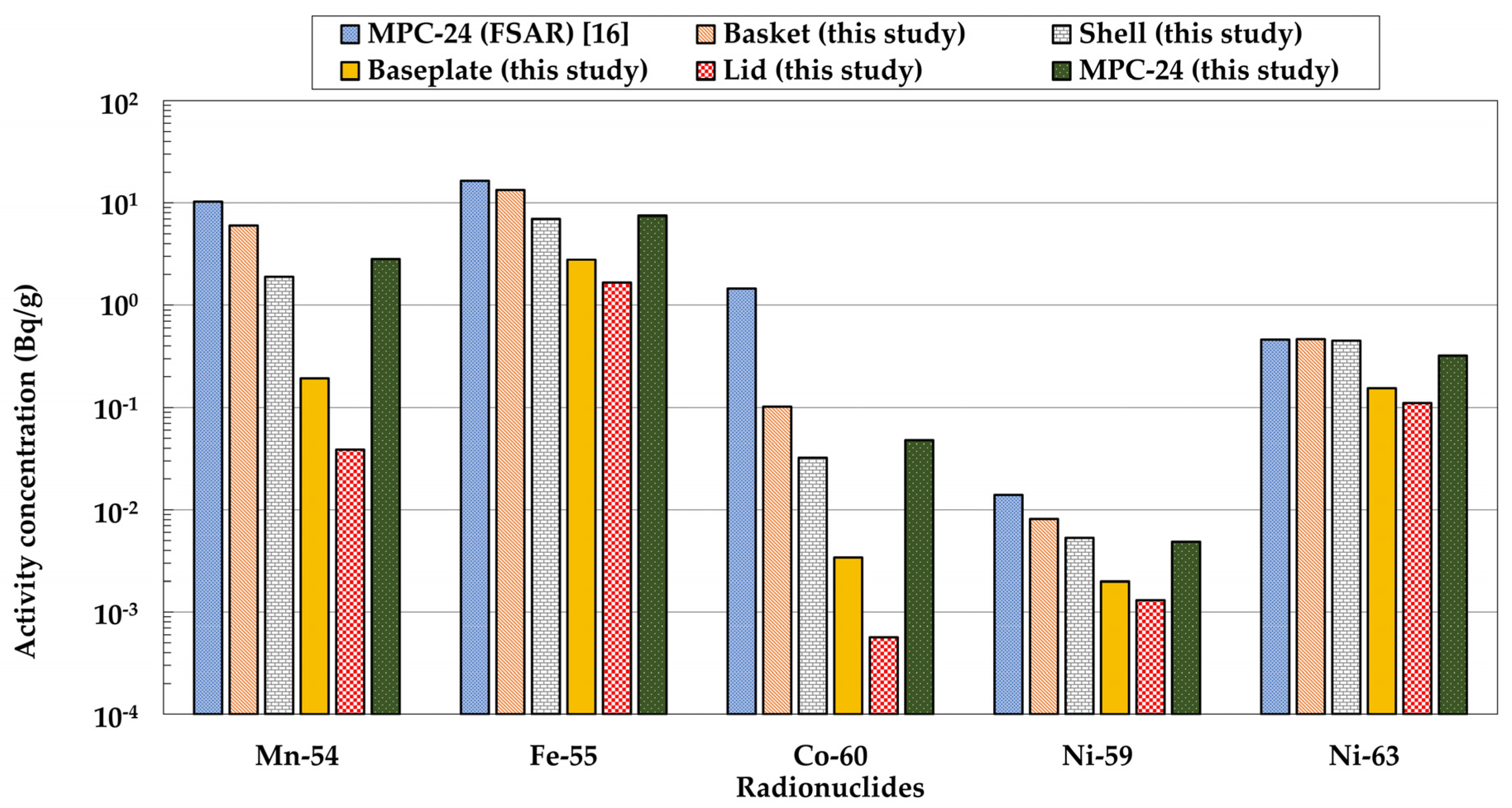
3.2. Application to and Comparison with a Representative Case in the HI-STORM 100 FSAR

In order to evaluate the applicability of the neutron activation analysis framework established in this study (see Figure 2), a set of comparative calculations was conducted for a representative case presented in Section 2.4 (Decommissioning considerations) of the HI-STORM 100 FSAR.
SNF of the PWR 15 × 15 (B&W) UO2 fuel type with a burnup of 70 GWD/MTU and 4.8 wt% of initial enrichment after five years of cooling after discharge was assumed for the activation calculation in the FSAR of the HI-STORM 100 [16]. The same conditions for the SNF were also assumed in this study for the neutron source term calculation, however, the SNF fuel type was assumed to be PWR 15 × 15 (WH) UO2 due to the unavailability of the cross-section library for PWR 15 × 15 (B&W) UO2 in the ORIGEN-ARP code (see Step 1 in Figure 2). PWR 15 × 15 (WH) UO2 and PWR 15 × 15 (B&W) UO2 fuel types have quite similar characteristics in that they have the same lattice and number of fuel pins, and the comparative initial uranium mass (i.e., PWR 15 × 15 (B&W) UO2 is just about 6% heavier). The neutron source terms for PWR 15 × 15 (WH) UO2 which were calculated in accordance with Step 1 of Figure 2 in this study cannot be directly compared with those for the PWR 15 × 15 (B&W) UO2, since the FSAR of the HI-STORM 100 does not provide specific information on the calculated neutron source terms.
In order to calculate the incident neutron fluxes and the reaction rates (see Step 2 in Figure 2), the results of the MCNP model for the same MPC of the HI-STORM 100 FSAR (see Figure 4) and isotopic composition of each component without impurities (see Table 4) were used. It is of note that the HI-STORM 100 FSAR neither provides the isotopic composition of materials (SS304) nor specifies explicitly whether impurities are considered. Then, the modified effective cross-section of each activation reaction was calculated in accordance with Step 3 in Figure 2, whereas the FSAR of the HI-STORM 100 does not address any cross-section libraries used and/or whether the default cross-section data are modified or not. Moreover, any computational tools for evaluating the neutron activation are not introduced in the FSAR, rather only the calculated activity concentration of five radionuclides (see Table 1) in the MPC-24 as a whole without partitioning each component. In this study, however, the residual radioactivity concentrations of the same five radionuclides were calculated as per Step 4 in Figure 2 for each component and the MPC-24 as a whole together with the results given in the FSAR (see Figure 7).
As shown in Figure 7, the calculated activity concentrations for the MPC-24 as a whole turned out to range from 0.014 to 16.5 Bq / g in the FSAR in decreasing order of 55Fe, 54Mn, 60Co, 63Ni, and 59Ni, and from 0.0049 to 7.5 Bq / g in this study in decreasing order of 55Fe, 54Mn, 63Ni, 60Co, and 59Ni. In this study, the residual radioactivity concentrations, except for 60Co, in the MPC-24 were calculated to be less than those given in the FSAR; the results of this study range from 27.47 to 69.93% of the residual radioactivity given in the HI-STORM 100 FSAR. Such an underestimation can be ascribed to the lower initial mass of uranium in the assumed nuclear fuel (PWR 15 × 15 (WH)) and the modified realistic cross-sections (see Section 3.1.3) in this study. Further, the composition of the HI-STORM 100 FSAR had more precursors (e.g., Fe and Ni for 69.5% and 9.5%, respectively) than this study. On the other hand, since the HI-STORM 100 FSAR only suggested the neutron activation calculation was conducted based on MCNP-4A, they might have used a general equation, as described in Equation (2), that could not reflect the depletion of the activation product by another neutron activation such as 60Co ( n , γ ) 61Co and 54Mn ( n , γ ) 55Mn, which have no negligible cross-section (0.781 and 0.242 barn in ORIGEN-2, respectively). Moreover, regarding the energy cut-off of the HI-STORM 100 FSAR, which only considered emitted neutrons above 100 keV from SNF which were dominant in ( n , p ) reactions (see Section 3.1.3), contrasting with this study (considering all energies from zero to 20 MeV), the ( n , p ) reactions are overestimated compared to this study. It is noted that the much lower residual activity concentration of 60Co calculated in this study (i.e., 3.49% of the HI-STORM 100 FSAR) may result from differences between the FSAR and this study such as material compositions assumed, activation calculation tools used, cross-section data input, and considered neutron energy groups in calculation. In spite of a few uncertainties in the input parameters and assumptions used for calculation in the FSAR, the assessed residual activities of the MPC-24 in the FSAR and in this study are quite comparable, which implies that the activation analysis framework developed in this study is applicable in practice.

3.3. Sensitivity Analysis for Design and/or Operation Parameters

A series of sensitivity analyses was conducted for four important design and/or operation parameters (i.e., fuel burnup, impurity content, cooling time after discharge, and storage time of the SNF in the DSS) which affect the neutron activation of the components of a DSS [49].

3.3.1. Effect of Fuel Burnup

Both the initial enrichment of 235U of nuclear fuel and its resulting burnup affect the neutron source terms in SNF as implied in Equation (3), however, the two parameters are generally proportional to each other; that is, the nuclear fuel with higher initial enrichment is usually irradiated longer in the reactor core and then discharged as SNF with higher burnup. However, the spent nuclear fuels are actually discharged from the reactor core after various burning times in accordance with the planned loading plans or due to an unplanned event [50]. Accordingly, the neutron source terms in the SNF to be stored were calculated at 4.2 wt% of the reference fuel enrichment but by varying the fuel burnup from 35 to 70 GWD/MTU at every 5 GWD/MTU using the ORIGEN-ARP code (see Step 1 in Figure 2). The residual radioactivity concentration of each radionuclide in the component of the MPC-24 was subsequently calculated using different neutron source terms derived as above in accordance with the same procedures (i.e., Steps 2 to 4 in Figure 2), and is shown in Figure 8 in terms of S o F which was calculated using Equation (1).
The higher value of S o F estimated for the higher burnup SNF in Figure 8, at a fixed initial enrichment, can be explained by the formation mechanism of the major neutron source, 244Cm, in the SNF with regard to the dry storage period. One of the representative minor actinides, 244Cm, is formed in the operation of a nuclear reactor primarily by the sequence of neutron capture and rapid beta decay reactions (see Reference [51]), and more 244Cm is accordingly produced in the higher burnup (i.e., more neutrons are produced and interact with fuel) SNF if the initial enrichment is fixed. In more detail, the S o F of the residual radioactivity in the basket of the MPC-24 decreases down to 4.42, 8.10, 13.7, and 21.66 by decreasing the burnup of 5 GWD/MTU in series from the reference condition (i.e., 55 GWD/MTU showing the S o F of 30.01), while the S o F increases up to 46.29, 63.49, and 83.95 by increasing the burnup in the same way from the reference condition.
It turns out that the S o F s for the basket and shell are to be over the unity of the range of fuel burnup, which means that both the basket and shell are activated high enough to be managed as a radioactive waste irrespective of the fuel burnup assumed in this study (see Figure 8a,b). In order to apply the clearance rule, the disused basket and shell should be in decay-in-storage for 1.9 to 8.3 years and 0.4 to 4.7 years, respectively, depending on the fuel burnup varying from 35 to 70 GWD/MTU. Meanwhile, Figure 8d shows that the lid could be managed as a non-radioactive waste in accordance with the clearance rule regardless of the assumed fuel burnup. On the other hand, the baseplate could be released from regulatory control without further consideration if the fuel burnup is less than 45 GWD/MTU, however, it should be temporarily stored for 0.2 to 1.9 years for clearance if its burnup ranges from 45 to 70 GWD/MTU (see Figure 8c). The above results imply that decay-in-storage of disused or dismantled components of a DSS could be a practical option to minimize the secondary radioactive waste ultimately disposed of at a dedicated repository based on accurate characterizations of burnup of the SNF to be stored.

3.3.2. Effect of Impurity Content

In the reference case of this study (see Section 3.1), only the elements and isotopes present in the SS304 material of the MPC-24 were taken in account for the activation calculation without consideration of potential impurities (see Table 4). Many investigators have reported that impurities beyond the prescribed contents are present in SS304 widely used as structural materials in the nuclear industry [5,16,18,24], however, an USNRC contractor’s study reported that the impurity content of 59Co measured in actual components at NPPs ranged from 229 to 2570 ppm [42]. Among others, 59Co is to be one of the important impurity contents to form a dominant activation product, 60Co, through 59Co ( n , γ ) 60Co, which emits high-energy gamma rays (i.e., 1.17 and 1.33 MeV) with a half-life longer than other major activation products except 59Ni and 63Ni (see Table 5), and thus has a highly conservative clearance level of 0.1   Bq / g (see Table 5) [19]. Therefore, the potential effect of 59Co impurity content on the residual radioactivity of MPC-24 was quantitatively analyzed by varying the 59Co content in SS304 at 0, 229, 614, 800, 1000, 1414, 2214, 2570, and 4700 ppm in accordance with the 59Co impurity content reported by the USNRC and in the HI-STORM 100 FSAR for radiation shielding design [16,42].
Before analyzing the sensitivity of the 59Co impurity for the neutron activation of structural materials, the modified effective microscopic cross-section for the 59Co ( n , γ ) 60Co reaction was calculated (see Step 3 in Figure 2). As a result, the modified effective cross-sections for the basket, shell, baseplate, and lid are 0.154, 1.04, 1.74, and 2.83 barn, respectively. It is noteworthy that the modified effective cross-section for the lid (2.83 barn) is even larger than the default one-group microscopic cross-section for the same activation reaction (2.01 barn) included in a typical built-in library for the PWR core region (i.e., PWRU50 in ORIGEN-2), which can be interpreted by a special resonance peak from 100 to 300 eV of the 59Co ( n , γ ) 60Co reaction where the cross-section is as high as 10,000 barn (see Figure 5) [47].
The residual activity in each MPC-24 component by varying the 59Co impurity content is shown in Figure 9 in terms of the S o F , along with the elapsed time after the end of the 40-year storage time, while other assumptions are kept the same as the reference case in Section 3.1.
The values of S o F s for all components including the lid of the MPC-24 exceed the unity if the impurity content of 59Co considered in the activation calculation, as shown in Figure 9, implies that the whole MPC components should be treated as a radioactive waste when their 59Co impurity is over 229 ppm in SS304. In addition, the calculated S o F of the residual radioactivity at the end of the storage time increases 2.32 to 27.93 times compared to the 59Co impurity-free case by increasing the 59Co impurity content from 229 to 4700 ppm. Though it is not explicitly depicted in Figure 9, it turned out that 1 ppm of the 59Co impurity produces 0.42, 0.71, 3.36, and 12.17 times more 60Co in the basket, shell, baseplate, and lid, respectively, compared to total 60Co produced by 60Ni ( n , p ) 60Co in each component without any impurity. The relatively higher production of 60Co from activation of the 59Co impurity in the lid can be ascribed to the higher modified effective cross-section (see above) and the higher neutron flux around the resonance peak area (see Figure 5) than the other components.
For the least activated component lid, it was estimated that the lid can be released from regulatory control after 15 to 37 years of decay-in-storage for the 59Co impurity content ranging from 229 to 4700 ppm. However, with regard to the most activated component, the basket, the clearance rule can be applied only after 29 to 51 years of decay-in-storage for 229 to 4700 ppm of the 59Co impurity. In contrast to the 59Co impurity-free case shown in Figure 8 where at most a few years of decay-in-storage is enough for clearance, it turns out that very long temporary storage could be needed for clearance of components if 59Co is present in the materials at an impurity concentration level actually observed or reported in the nuclear industry. Therefore, the content of 59Co as an impurity in the structural material of DSSs is expected to be one of the most important factors in determining whether the secondary waste from disused DSSs should be managed as a radioactive waste or as a non-radioactive conventional metal waste.
The above results infer different levels of impurity controls are required for effective radioactive waste management of each component from disused DSSs. Further, the decay-in-storage strategy for clearance would not be effective if the impurity of the materials in the DSS is not appropriately controlled. In other words, the impurity content control on the actual structural materials of DSSs is also needed to minimize the secondary radioactive waste and to improve the accuracy of the results from the activation analysis framework established in this study (see Figure 2). This argument conforms to the recommendations of the competitive international organizations on the selection of low-activation materials which will simplify and minimize the generation of activated materials and radioactive waste during the decommissioning of nuclear facilities [52,53].

3.3.3. Effect of Fuel Cooling Time after Discharge

As implied in Equation (3) and Figure 3, the longer the SNF is cooled down in SFP after being discharged from the reactor core, the lower the neutron source terms of the SNF to be stored in a DSS, and the lower the residual radioactivity in the components of the DSS to be calculated. Thus, the residual radioactivity concentration of each radionuclide in the component of the MPC-24 was calculated for different fuel cooling times 5 to 30 years after discharge, shown in Figure 10 in terms of the S o F , while all other conditions and assumptions are kept the same as the reference case in Section 3.1.
As shown in Figure 10, the shorter fuel cooling time after discharge conforms to the higher value of S o F of the residual radioactivity of the MPC-24, which is attributed to the more neutrons emitted from the less cooled-down SNF all through the dry storage period. The S o F evaluated right after the end of dry storage of SNF which has been cooled down 5 and 30 years turned out to be 120.6% and 47.5% of the S o F calculated for the reference case (i.e., storage of 10-year cooled-down SNF), however, the fuel cooling time does not impact the neutron activation of the DSS as a sensitive parameter. It was evaluated that the S o F of the major activation products decreases only about 3.7% per one-year longer cooling time of the SNF. In other words, the required decay-in-storage time for clearance is shown to be shortened by around 1.5 years by increasing the fuel cooling time from 5 to 30 years for the basket, and shortened by just about 1.1 and 0.3 years for the shell and baseplate. The above observation conforms to the fact that the minimum fuel cooling time essentially designated for a commercial DSS (e.g., five years for PWR 15 × 15 (B&W) fuel type for the MPC-24 of the HI-STORM 100) is usually determined from nuclear criticality and/or thermal analysis for the DSS rather than from the decommissioning assessment to minimize secondary waste [16,54]. Accordingly, it can be concluded that just an increasing fuel cooling time would not be an effective strategy to minimize the secondary radioactive waste compared to controlling the impurity content (see Section 3.3.2). All the more, it is noteworthy that increased wet storage/cooling time in the SFP could produce more secondary radioactive waste from operation of the SFP cleanup system, which may exceed the anticipated radioactive activation products to be reduced by increasing the fuel cooling time [3].

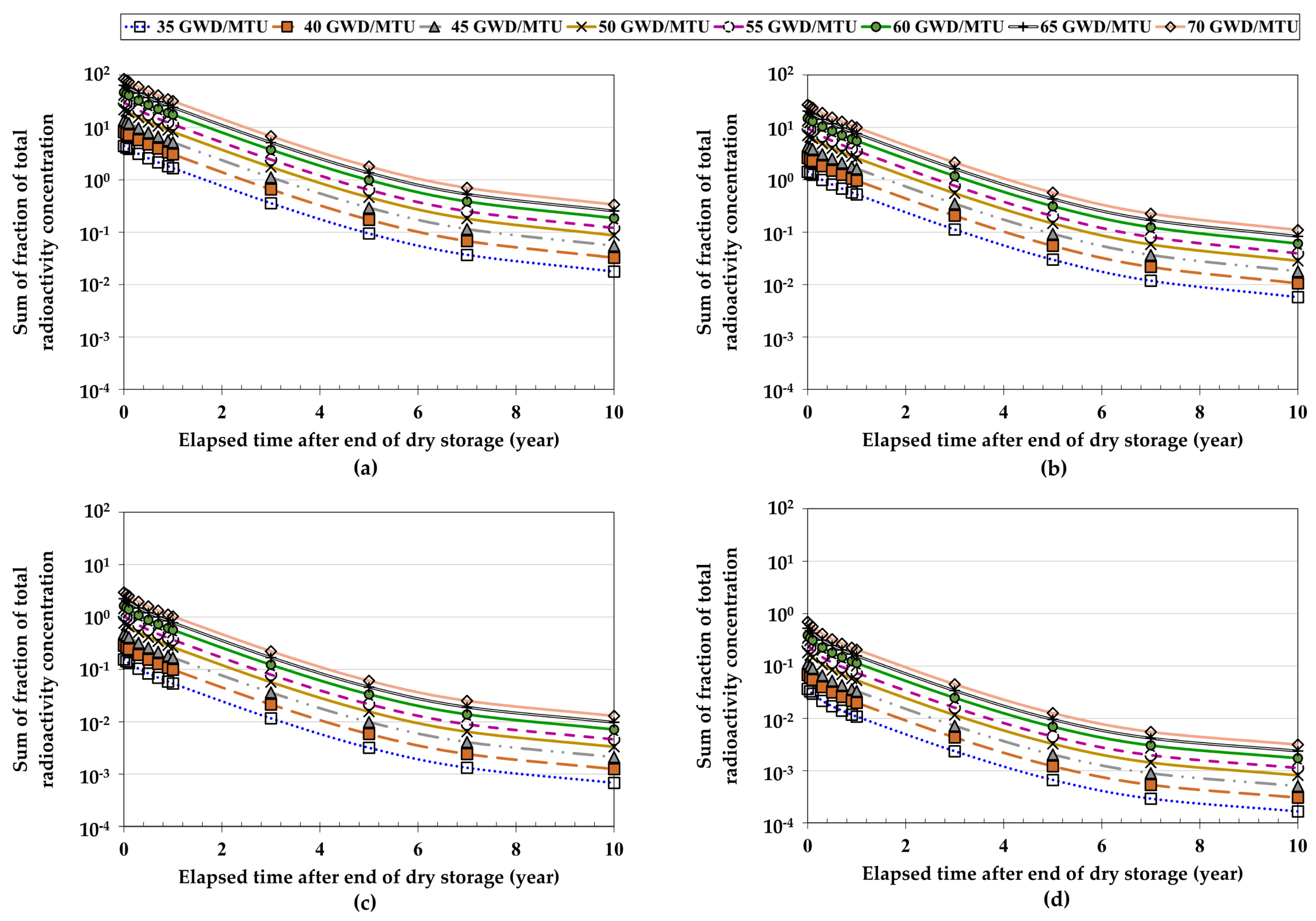
3.3.4. Effect of Dry Storage Time of SNF

In this section, the effect of dry storage time on the residual radioactivity of MPC-24 components was analyzed in order to find the implications of potential extended long-term storage of SNF proposed by a few countries [55,56]. The residual radioactivity of each MPC-24 component was calculated using the same conditions (e.g., constant neutron source terms all through the dry storage period) as given in the reference case (see Section 3.1) except for the variable dry storage time 0 to 100 years, rather than a fixed-term (i.e., 40 years) dry storage for the design lifetime of the DSS, and the results for the most affecting basket are shown in Figure 11.
Figure 11a shows that the S o F for the basket is to be almost saturated after 10 years of dry storage around 30, which is the same result shown in Figure 6a under the constant neutron sources. This type of saturation is caused by much shorter half-lives of major activation products (e.g., 54Mn, 58Co, and 60Co) than the dry storage time, and is comparable to the saturation model curve for an infinite number of parent nuclei for a radionuclide production through neutron activation at an accelerator or nuclear reactor [57]. The little effect of the irradiation time on the residual activity of activation products of the DSS also conforms to a previous study on the neutron activation of a nuclear reactor structure which reported that the difference of total specific activity induced by 30-year and 50-year operation periods is just 3% at most [5]. On the other hand, the S o F shows a peak after five years of dry storage and then decreases along with time under the realistic assumption of time-dependent neutron source terms. The S o F s after 40 years and 100 years of dry storage are calculated to be 8.37 and 1.37, respectively. It implies that the basket should still be managed as a radioactive waste after the extended long-term storage (i.e., 100 years), since its S o F exceeds unity even under the realistic assumption. Nevertheless, the basket is to be released from regulatory control just after 0.3 years of decay-in-storage.
Figure 11b presents the residual activity concentration of a representative short-lived radionuclide, 60Co, and a long-lived one, 63Ni, in the basket under the assumptions of constant or time-dependent neutron source terms. For the conservative constant neutron source terms, the activity concentration of 60Co is saturated after 65 years of dry storage, while that of the longer-lived 63Ni increases continuously over the whole storage time. In contrast, the activity concentration of 60Co shows a peak after 15 years of dry storage and subsequently decreases to the end for the time-dependent neutron source terms. Under the same realistic neutron source terms, the activity concentration of 63Ni still increases during the dry storage period but much more slowly compared to the above case with a conservative assumption. The above observations show that the long-lived activation products in the DSS increase during the timeframe of dry storage, even if the S o F curves in Figure 11a are shown to be saturated or even decreased with storage time.
Through this, it can be concluded that the possible extended long-term storage of SNF beyond the design lifetime of 40 years assumed for the DSS in this study (e.g., dry storage for longer than 100 years) may not cause any significant issues regarding the minimization of secondary radioactive waste from the decommissioning of the DSS. Besides, no further consideration of the minimization of activated secondary waste from a DSS is to be guaranteed if the canister of a DSS can be directly disposed of at a deep geological repository in the future without re-encapsulation of the SNF into a disposal canister as proposed in the Transportation, Aging and Disposal (TAD) canister-based system [58,59].

4. Conclusions

A systematic four-step assessment framework for the neutron activation of components of a DSS for SNF, which consists of calculation of neutron source terms (ORIGEN-ARP), calculation of incident neutron flux and reaction rate (MCNPX), modification of effective cross-section (hand calculation), and calculation of residual activity concentration (ORIGEN-2), has been established, along with its technical bases in this study.
For a reference case to store PWR 16 × 16 (CE) SNF assemblies in a stainless steel (SS304) canister, MPC-24 of the HI-STORM 100, for 40 years after 10-years cooling in an SFP, the dominant neutron sources turn out to be an ( α , n ) reaction and spontaneous fission of a minor actinide, 244Cm, in the SNF all through the storage period. The relative fraction of the incident neutron flux with relatively high energy to each component of the MPC-24 decreases in the basket, shell, baseplate, and lid in order, while the fraction of incident neutron with relatively low energy decreases in reversed order, which was attributed to the slowdown of the incident neutron energy and the axial burnup distribution. The cumulative neutron emissions from the stored SNF turned out to be about 60% of the conservative assumption of the constant neutron emission rate all through the storage time which has been widely adopted in the safety assessment of commercial DSSs. Eight radionuclides (51Cr, 54Mn, 55Fe, 59Fe, 58Co, 60Co, 59Ni, and 63Ni) were calculated to be mainly formed due to eight activation reactions in the MPC-24 without any impurities through ( n , γ ) or ( n , p ) reactions. An effective cross-section for each activation reaction and each component was derived to be lower than the respective built-in one-group cross-section in the PWRU50 library for the typical PWR core region. It was also shown that the modified effective cross-section is to be affected by the relative distribution of the incident neutron energy rather than by the absolute magnitude of the neutron flux. The higher modified effective cross-section of ( n , γ ) in the lid compared to the basket of the MPC-24 was explained by the general dominance of the relatively lower-energy neutron in ( n , γ ) reactions, whereas the higher modified effective cross-section of ( n , p ) in the basket can be ascribed to the higher cross-section of ( n , p ) in the relatively higher neutron energy band.
The established assessment framework was applied to a representative case analyzed in the HI-STORM 100 FSAR using given data and inevitable assumptions results from 27.5 to 69.9% of the residual activity of seven radionuclides (except 60Co) in components shown in the FSAR. The underestimation was ascribed to the realistic modification of effective cross-sections conducted in this study and the higher mass of uranium in PWR 15 × 15 (B&W) fuel in the FSAR compared to PWR 15 × 15 (WH) fuel assumed in this study due to the limited built-in library of the ORIGEN-ARP code. Higher underestimation for 54Mn and 60Co (i.e., 27.5% and 3.5% of the FSAR result) was further interpreted by the differences of material compositions, activation calculation tools, cross-sections, and cutting off of the specific neutron energy group between the FSAR and this study.
Through sensitivity analyses with regard to fuel burnup, impurity content, fuel cooling time, and storage time, a series of implications has been derived. Burnup change of −25 to +15 GWD/MTU from the reference condition (i.e., 55 GWD/MTU) causes −85% to +180% change of the S o F of residual radioactivity in MPC-24 components and subsequently −2.6 to +1.5-years change of the required decay time for clearance, which implies that characterization of the SNF in terms of burnup and a decay-in-storage should be considered as a strategy to minimize generation of the secondary waste in using DSSs. It turned out that 1 ppm of 59Co produces 0.42 to 12.17 times of 60Co which is the total 60Co activity of the non-impurity case, produced by the 60Ni ( n , p ) 60Co reaction, and the content of 59Co in the MPC-24, within the reported range (i.e., 229 to 4700 ppm), delays the required decay time for clearance by 15 to 51 years. Accordingly, impurity control of component materials is essential for minimizing secondary radioactive waste from DSS, since such a long decay time is generally not practicable at nuclear facilities. In contrast to other activation reactions, the modified effective cross-section of 59Co ( n , γ ) 60Co for the lid is even higher than the respective unchanged cross-section in the built-in PWRU50 library of ORIGEN-2, which was explained by a resonance peak (~10,000 barns) observed around the 100 to 300 eV neutron energy region of the reaction in which the calculated relative fraction of ϕ ( E ) in the lid is higher than that of a typical PWR core region.
In contrast to fuel burnup and impurities, fuel cooling time and dry storage period did not significantly affect the neutron activation of the DSS. Though the lower level of residual activity was calculated for the MPC-24 storing the SNF cooled down in SFP for a longer time from 10 to 30 years, its effect turned out to be not so significant. Even if the longer storage time of SNF in the DSS may induce further activation of its components, on the other hand, the residual activity in terms of the S o F almost shows a saturation after around 10 years of dry storage. Hence, a newly proposed concept of extended long-term storage of SNF in a DSS for longer than 100 years may not cause any implications due to a gradual decrease in neutron sources in the SNF stored along with the storage time.
Based upon the results, impurity control of the structural materials of the DSS at the design or manufacturing stages and appropriate decay-in-storage of the neutron-activated components after its design lifetime are suggested, in order to manage and minimize the generation of secondary radioactive waste from the decommissioning of dry storage systems for spent nuclear fuel. The framework and insights of the neutron activation analysis of the DSS proposed in this study could be used to optimize the strategy for effective management of waste to be generated from the DSS.

Author Contributions

J.H.C. provided the main idea of the study; S.G.L. performed the modeling of methodology and calculation with formal analysis; S.G.L. wrote the original draft; J.H.C. reviewed and edited the draft. All authors have read and agreed to the published version of the manuscript.

Funding

This research was supported by the Nuclear Safety Research Program through the Korea Foundation Of Nuclear Safety (KOFONS), granted financial resource from the Nuclear Safety and Security Commission (NSSC), Republic of Korea (Grant number: 1605008). This research was supported by “Human Resources Program in Energy Technology” of the Korea Institute of Energy Technology Evaluation and Planning (KETEP), granted financial resource from the Ministry of Trade, Industry & Energy, Republic of Korea (Grant number: 20184030202170).

Conflicts of Interest

The authors declare no conflict of interest.

References

  1. Howard, R.; Van den Akker, B. Consideration for disposition of dry cask storage system materials at end of storage system life. In Proceedings of the Symposium on Recycling of Metals arising from Operation and Decommissioning of Nuclear Facilities, Norrkoping, Sweden, 8–10 April 2014. [Google Scholar]
  2. United States Government Accountability Office. Spent Nuclear Fuel Accumulating Quantities at Commercial Reactors Present Storage and Other Challenges; United States Government Accountability Office: Washington, DC, USA, 2012.
  3. Romanato, L.S. Advantages of dry hardened cask storage over wet storage for spent nuclear fuel. In Proceedings of the 2011 International Nuclear Atlantic Conference—INAC 2011, Belo Horizonte, MG, Brazil, 24–28 October 2011. [Google Scholar]
  4. Pantelias, M.; Volmert, B. Activation neutronics for a swiss pressurized water reactor. Nucl. Technol. 2015, 192, 278–285. [Google Scholar] [CrossRef]
  5. Cha, G.Y.; Kim, S.Y.; Lee, J.M.; Kim, Y.S. The effects of impurity composition and concentration in reactor structure material on neutron activation inventory in pressurized water reactor. J. Nucl. Fuel Cycle Waste Technol. 2016, 14, 91–100. [Google Scholar] [CrossRef]
  6. Ahn, J.G.; Lee, M.H.; Ahn, H.C. Analysis of activation source terms of spent nuclear fuel rack for decommissioning of nuclear power plants. In Abstracts of Proceedings of the Korean Radioactive Waste Society Autumn 2013; Korean Radioactive Waste Society: Daejeon-si, Korea, 2013; Volume 11, pp. 135–136. [Google Scholar]
  7. United States Nuclear Regulatory Commission. Standard Review Plan for Spent Fuel Dry Storage Systems at a General License Facility; NUREG-1536, Revision 1; USNRC: Washington, DC, USA, 2010.
  8. International Atomic Energy Agency. Spent Fuel Storage and Transport Cask Decontamination and Modification; TECDOC-1081; IAEA: Vienna, Austria, 1999. [Google Scholar]
  9. United States Nuclear Regulatory Commission. Standard Review Plan for Dry Cask Storage Systems; NUREG-1536, Revision 0; USNRC: Washington, DC, USA, 1997.
  10. United States Nuclear Regulatory Commission. Standard Format and Content for a Topical Safety Analysis Report for a Spent Fuel Dry Storage Cask; Regulatory Guide 3.61, Revision 1; USNRC: Washington, DC, USA, 2010.
  11. United States Nuclear Regulatory Commission. Standard Review Plan. for Spent Fuel Dry Storage Facilities; NUREG-1567, Revision 1; USNRC: Washington, DC, USA, 2000.
  12. TLG Services, Inc. Decommissioning Cost Analysis for the Salem Generation Station; TLG Services, Inc.: Bridgewater, CT, USA, 2015. [Google Scholar]
  13. Welsch, J.M. 10 CFR 72.30 Diablo Canyon Independent Spent Fuel Storage Installation Decommissioning Cost Estimate. Available online: https://www.nrc.gov/docs/ML1835/ML18351A368.pdf (accessed on 20 June 2020).
  14. Transnuclear, Inc. TN-32 Final Safety Analysis Report; Transnuclear, Inc.: New York, NY, USA, 2002. [Google Scholar]
  15. Transnuclear, Inc. Final Safety Analysis Report for the TN-68 Dry Storage Cask; Transnuclear, Inc.: New York, NY, USA, 2000. [Google Scholar]
  16. Holtec International. Final Safety Analysis Report for the HI-STORM 100 Cask System; Holtec International: Mount Laurel, NJ, USA, 2016. [Google Scholar]
  17. NAC International. Final Safety Analysis Report for the UMS Universal Storage System; NAC International: Peachtree Corners, GA, USA, 2016. [Google Scholar]
  18. Kim, T.-M.; Ku, J.-Y.; Dho, H.-S.; Cho, C.-H.; Ko, J.-H. Activation analysis of dual-purpose metal cask after the end of design lifetime for decommissioning. J. Nucl. Fuel Cycle Waste Technol. 2016, 14, 343–356. [Google Scholar] [CrossRef]
  19. International Atomic Energy Agency. Radiation Protection and Safety of Radiation Sources: International Basic Safety Standards; General Safety Requirements No. GSR Part 3; IAEA: Vienna, Austria, 2014. [Google Scholar]
  20. International Atomic Energy Agency. Methodologies for Assessing the Induced Activation Source Term for Use in Decommissioning Applications; Safety Reports Series No. 95; IAEA: Vienna, Austria, 2019. [Google Scholar]
  21. Kruijf, W.J.M.; Janssen, A.J. Detailed Resonance Absorption Calculations with the Monte Carlo Code MCNP and A Collision Probability Version of the Slowing Down Code ROLAIDS; Netherlands Energy Research Foundation ECN: Petten, The Netherlands, 1993. [Google Scholar]
  22. Sanghwa, S.; Jooho, W. A study on source term assessment of the Kori unit-1 reactor vessel. J. Nucl. Sci. Technol. 2004, 4, 86–89. [Google Scholar]
  23. Cho, D.-K.; Choi, H.-J.; Ahmed, R.; Heo, G. Radiological characteristics of decommissioning waste from a CANDU reactor. Nucl. Eng. Technol. 2011, 43, 583–592. [Google Scholar] [CrossRef] [Green Version]
  24. Noh, K.; Hah, C.J. Verification of MCNP/ORIGEN-2 model and preliminary radiation source term evaluation of Wolsung Unit 1. J. Nucl. Fuel Cycle Waste Technol. 2015, 13, 21–34. [Google Scholar]
  25. Jang, M.; Lim, J.M.; Kim, H.C.; Kim, C.-J. Inventory estimation of 36Cl and 41Ca in concrete of Kori Unit 1. J. Nucl. Fuel Cycle Waste Technol. 2019, 17, 121–126. [Google Scholar]
  26. Ministry of Trade, Industry & Energy (MoTIE). The Basic Plan on High-Level Radioactive Waste Management; MoTIE: Sejong-si, Korea, 2016.
  27. Robert, H.J., Jr. Dry Storage Cask Inventory Assessment; SRNL: Jackson, SC, USA, 2016. [Google Scholar]
  28. Korea Electric Power Corporation (KEPCO); Korea Hydro and Nuclear Power Co. (KHNP), Ltd. APR1400 Design Control Document Tier 2; KHNP: Gyeongju-si, Korea, 2018. [Google Scholar]
  29. Yuk, D.-S.; An, S.-M.; Jeong, H.-Y.; Lee, H.-J. Analysis of Standardized Data for Spent Fuel in Korea; KOFONS: Seongnam-si, Korea, 2016. [Google Scholar]
  30. Springman, R. Multi-purpose canisters for long-term interim storage. In Proceedings of the International Conference on Management of Spent Fuel from Nuclear Power Reactors: An Integrated Approach to the Back End of the Fuel Cycle, Vienna, Austria, 15–19 June 2015. [Google Scholar]
  31. United States Nuclear Regulatory Commission. Neutron Activation and Activation Analysis; NRC/HR-0751-H122; USNRC: Washington, DC, USA, 2011.
  32. Skutnik, S. ORIGEN-Based Nuclear Fuel Inventory Module for Fuel Cycle Assessment; University of Tennessee-Knoxville: Knoxville, TN, USA, 2017. [Google Scholar]
  33. Kryuchkov, E.F.; Opalovsky, V.A.; Tikhomirov, G.V. Comparative analysis of radiation characteristics from various types of spent nuclear fuel. In Proceedings of the International Conference on Supercomputing in Nuclear Applications SNA’2003, Paris, France, 22–24 September 2003. [Google Scholar]
  34. Bowman, S.M.; Gauld, I.C. OrigenArp Primer: How to Perform Isotopic Depletion and Decay Calculations with SCALE/ORIGEN; ORNL: Oak Ridge, TN, USA, 2010.
  35. Hermann, O.W.; Westfall, R.M. ORIGEN-S: Scale System Module to Calculate Fuel Depletion, Actinide Transmutation, Fission Product Buildup and Decay, and Associated Radiation Source Terms; NUREG/CR-0200, Revision 6; USNRC: Washington, DC, USA, 1998; Volume 2.
  36. Denise, B. Pelowitz. MCNPXTM User’s Manual Version 2.5.0; LANL: Los Alamos, NM, USA, 2005. [Google Scholar]
  37. Źerovnik, G.; Podvratnik, M.; Snoj, L. On normalization of fluxes and reaction rates in MCNP criticality calculations. Ann. Nucl. Energy 2014, 63, 126–128. [Google Scholar] [CrossRef]
  38. Hadd, K.; Nematolahi, M.; Golestani, A. VVER-1000 Cross-section Library Generation for ORIGEN-II based on MCNP Calculations. Int. J. Hydrogen Energy 2015, 40, 15158–15163. [Google Scholar] [CrossRef]
  39. Syarip, S.; Sutondo, T. Analytical method of atomic density determination of uranyl nitrate solution. J. Phys. Confer. Ser. 2018, 1090, 012036. [Google Scholar] [CrossRef]
  40. The American Society of Mechanical Engineers. An International Code 2019 ASME Boiler & Pressure Vessel Code Section II: Materials-Part A: Ferrous Material Specifications (Beginning to SA-450); ASME BPVC. II. A-2019; ASME: New York, NY, USA, 2019. [Google Scholar]
  41. Commission on Isotopic Abundances and Atomic Weights. Available online: https://www.ciaaw.org/atomic-weights.htm (accessed on 28 August 2020).
  42. Evans, J.C.; Lepel, E.L.; Sanders, R.W.; Wilkerson, C.L.; Silker, W.; Thomas, C.W.; Abel, K.H.; Robertson, D.R. Long-Lived Activation Products in Reactor Material; NUREG/CR-3474; USNRC: Washington, DC, USA, 1984.
  43. Croff, A.G. A User’s Manual for the ORIGEN2 Computer Code; ORNL: Oak Ridge, TN, USA, 1980.
  44. Ullah, S.; Awan, S.E.; Mirza, N.M.; Mirza, S.M. Source term evaluation for the upgraded LEU Pakistan research Reactor-1 under severe accidents. Nucl. Eng. Des. 2010, 240, 3740–3750. [Google Scholar] [CrossRef]
  45. Wagner, J.C.; Dehart, M.D. Review of Axial Burnup Distribution Considerations for Burnup Credit Calculations; ORNL: Oak Ridge, TN, USA, 1999.
  46. McAlister, D.R. Neutron Shielding Materials Revision 2.1; 1955 University Lane Lisle: Lisle, IL, USA, 2016. [Google Scholar]
  47. Koning, A.J.; Rochman, D.; Sublet, J.; Dzysiuk, N.; Fleming, M.; Van der Marck, S. TENDL: Complete nuclear data library for innovative nuclear science and technology. Nucl. Data Sheets 2019, 155, 1–55. [Google Scholar] [CrossRef]
  48. Zhang, T.; Xiong, J.; Liu, X.; Chai, X.; Li, W.; Cheng, X. Conceptual design of an innovative reduced moderation thorium-fueled small modular reactor with heavy-water coolant. Int. J. Energy Res. 2019, 43, 8286–8298. [Google Scholar] [CrossRef]
  49. Bevard, B.B.; Wagner, J.C.; Parks, C.V.; Aissa, M. Review of Information for Spent Nuclear Fuel Burnup Confirmation; NUREG/CR-6998; USNRC: Washington, DC, USA, 2009.
  50. Dho, H.-S.; Kim, T.-M.; Cho, C.-H. The evaluation of minimum cooling period for loading of PWR spent nuclear fuel of a dual purpose metal cask. J. Nucl. Fuel Cycle Waste Technol. 2016, 14, 411–422. [Google Scholar]
  51. Posey, J.C. Curium-244 Isotopic Power Fuel—Chemical Recovery from Commercial Power Reactor Fuels; ORNL: Oak Ridge, TN, USA, 1973.
  52. The Organisation for Economic Co-Operation and Development Nuclear Energy Agency. Decommissioning Considerations for New Nuclear Power Plants; NEA No.6833; OECD/NEA: Paris, France, 2010. [Google Scholar]
  53. International Atomic Energy Agency. Managing the Unexpected in Decommissioning; IAEA Nuclear Energy Series No. NW-T-2.8; IAEA: Vienna, Austria, 2016. [Google Scholar]
  54. TN Americas LLC. NUHOMS® EOS System Final Safety Analysis Report; TN Americas LLC: Columbia, MD, USA, 2017. [Google Scholar]
  55. Bare, W.C.; Torgerson, L.D.; Kenneally, R.M. Dry Cask Storage Characterization Project-Phase 1: CASTOR V/21 Cask Opening and Examination; NUREC/CR-6745; USNRC: Washington, DC, USA, 2001.
  56. The Organisation for Economic Co-operation and Development Nuclear Energy Agency. The Safety of Long-Term Interim Storage Facilities in NEA Member Countries; NEA/CSNI/R(2017)4; OECD/NEA: Paris, France, 2017. [Google Scholar]
  57. Podgoršak, E.B. Activation of nuclides. In Radiation Physics for Medical Physicists, 2nd ed.; Springer International Publishing: Cham, Switzerland, 2016; pp. 281–311. [Google Scholar]
  58. United States Nuclear Regulatory Commission. Generic Environmental Impact Statement for Continued Storage of Spent Nuclear Fuel; NUREG-2157; USNRC: Washington, DC, USA, 2014; Volume 1.
  59. Korea Radioactive Waste Agency. Development of a National-Level Spent Fuel Management Standardization System; Korea Radioactive Waste Agency: Gyeongju-si, Korea, 2016. [CrossRef]
Figure 1. Conceptual view of the HI-STORM 100 DSS to store PWR SNF [16]: (a) concrete overpack and multi-purpose canister (MPC), and (b) cross-section view of MPC-24.
Energies 13 05325 g001
Figure 2. Overall neutron activation analysis framework established in this study.
Energies 13 05325 g002
Figure 3. Neutron emission rate of each energy group from an assembly of SNF in the reference case.
Energies 13 05325 g003
Figure 4. Geometrical model of the HI-STORM 100 DSS developed for the MCNP calculation.
Energies 13 05325 g004
Figure 5. Fraction of incident flux of neutrons having a specific energy in each component.
Energies 13 05325 g005
Figure 6. Fraction of estimated radioactivity concentration to the clearance level of each radionuclide together with the sum of fractions for each MPC-24 component: (a) basket, (b) shell, (c) baseplate, and (d) lid.
Energies 13 05325 g006
Figure 7. Comparison of residual radioactivity concentrations of major activation products in each component of the MPC-24 and as a whole calculated in this study, together with the results provided in the HI-STORM 100 final safety analysis report (FSAR).
Energies 13 05325 g007
Figure 8. Sum of fractions of the estimated radioactivity concentration to the clearance level of each radionuclide for each MPC-24 component: (a) basket, (b) shell, (c) baseplate, and (d) lid.
Energies 13 05325 g008
Figure 9. Sum of fractions of the estimated radioactivity concentration to the clearance level of each radionuclide, by varying the 59Co impurity content in SS304 at 0, 229, 614, 800, 1000, 1414, 2214, 2570, and 4700 ppm, for each MPC-24 component: (a) basket, (b) shell, (c) baseplate, and (d) lid.
Energies 13 05325 g009
Figure 10. Sum of fractions of the estimated radioactivity concentration to the clearance level of each radionuclide, by varying fuel cooling times 5, 10, 15, 20, and 30 years after discharge from the reactor core, for each MPC-24 component: (a) basket, (b) shell, (c) baseplate, and (d) lid.
Energies 13 05325 g010
Figure 11. Residual radioactivity in the basket of the MPC-24, along with dry storage time of SNF with constant or time-dependent neutron source terms: (a) S o F of residual radioactivity, and (b) residual radioactivity concentrations of 60Co and 63Ni.
Energies 13 05325 g011
Table 1. Assumptions, conditions, and approaches for neutron activation calculations adopted in four types of commercialized dry storage systems (DSSs) for spent nuclear fuel (SNF) and one relevant study.
ItemCommercial DSSsPast Study [18]
TN-32 [14]TN-68 [15]HI-STORM 100 [16]NAC UMS [17]
SNF source term calculation modelSAS2H and ORIGEN-SSAS2H and ORIGEN-SSAS2H and ORIGEN-SSAS2HORIGEN-S
Neutron transport calculation modelXSDRN-PMXSDRN-PMMCNP-4AN/AMCNP5
Activation cross-section libraryORIGEN-2 PWRUORIGEN-2 BWRUN/AN/A 1Modified ORIGEN-2 PWRU50
Material of canisterStainless steel 304Stainless steel 304Stainless steel 304Stainless steel 304Stainless steel 304
Target radionuclides51Cr, 54Mn, 55Fe, 59Fe, 58Co, 60Co, 59Ni, 63Ni51Cr, 54Mn, 55Fe, 59Fe, 58Co, 60Co, 59Ni, 63Ni54Mn, 55Fe, 60Co, 59Ni, 63Ni54Mn, 55Fe, 60Co, 59Ni, 63Ni51Cr, 54Mn, 55Fe, 59Fe, 58Co, 60Co, 59Ni, 63Ni
S o F 400
(Basket)
32
(Basket)
117
(Canister)
50
(Canister bottom)
4.3
(Basket)
Fuel typePWR 17 × 17
(WH)
BWR 7 × 7
(GE)
PWR 15 × 15
(B&W)
PWR 17 × 17
(WH)
PWR 17 × 17
(WH)
Fuel burnup
(GWD/MTU)
4540704045
Initial enrichment
(wt % of 235U)
3.53.34.83.74.5
Cooling time (years)7105510
Element compositionGivenGivenGivenN/AGiven
Isotope compositionN/AN/AN/AN/AN/A
Impurities dataN/AN/AN/AN/AGiven
1 N/A means not addressed.
Table 2. Reference conditions of target SNF for neutron activation calculation in this study [28,29].
ItemConditionReference
Fuel typePWR 16 × 16 (CE) UO2[28]
Burnup55 GWD/MTU[29]
Initial enrichment4.2 wt% of 235U[29]
Refueling intervals540 days (18 months)[28]
Cooling time after discharge from reactor core10 yearsAssumed in this study
Table 3. Geometrical and dimensional characteristics of the HI-STORM 100 DSS together with the boundary conditions [16].
Component or ObjectDimension 1 (mm)
Concrete overpack3366 (OD) × 5874 (H)
Inner cavity1867 (OD) × 4839 (H)
MPC1737 (OD) × 4839 (H)
Shell1737 (OD) × 1711 (ID) × 4839 (H)
Baseplate1711 (OD) × 635 (H)
Lid1711 (OD) × 2413 (H)
Boundary condition 24000 (from DSS center)
1 OD, ID, and H represent the outer diameter, inner diameter, and the height, respectively. 2 A spherical void boundary condition was fixed at 400 cm from the center of the DSS.
Table 4. Isotopic composition of the MPC-24 of the HI-STORM 100 DSS derived for the MCNP calculation.
ElementIsotopeIsotopic CompositionElementIsotopeIsotopic Composition
C12C7.914 × 10−4S32S2.850 × 10−4
13C8.560 × 10−6Mn55Mn2.000 × 10−2
N14N1.000 × 10−3Fe54Fe4.018 × 10−2
Si28Si6.917 × 10−356Fe6.330 × 10−1
29Si3.514 × 10−457Fe1.457 × 10−2
30Si2.319 × 10−458Fe1.939 × 10−3
P31P4.500 × 10−4Ni58Ni6.297 × 10−2
Cr50Cr8.256 × 10−360Ni2.426 × 10−2
52Cr1.592 × 10−161Ni1.054 × 10−3
53Cr1.805 × 10−262Ni3.362 × 10−3
54Cr4.494 × 10−364Ni8.562 × 10−4
Table 5. Selected target radionuclides for activation calculation and major activation reactions [14,15,16,17,18,19].
RadionuclideHalf-LifeMajor Activation ReactionClearance Level [19]
51Cr27.7 days50Cr ( n , γ ) 51Cr 100   Bq / g
54Mn312.3 days54Fe ( n , p ) 54Mn 0.1   Bq / g
55Fe2.74 years54Fe ( n , γ ) 55Fe 1000   Bq / g
59Fe44.5 days58Fe ( n , γ ) 59Fe 1   Bq / g
58Co70.86 days58Ni ( n , p ) 58Co 1   Bq / g
60Co5.27 years60Ni ( n , p ) 60Co 0.1   Bq / g
59Ni76,000 years58Ni ( n , γ ) 59Ni 100   Bq / g
63Ni100.1 years62Ni ( n , γ ) 63Ni 100   Bq / g
Table 6. Comparison of built-in cross-section library in ORIGEN-2 and modified effective microscopic cross-section calculated in this study.
Reaction TypeCross-Section in PWRU50
(Barn)
Modified Cross-Section (Barn)Ratio of Modified to Built-In Cross-Section
BasketLidBasketLid
50Cr ( n , γ ) 51Cr1.253.18 × 1021.28 × 1012.97%10.22%
54Fe ( n , p ) 54Mn 2.05 × 1028.35 × 1036.87 × 10440.68%3.35%
54Fe ( n , γ ) 55Fe 1.80 × 1011.65 × 10=22.73 × 1029.15%15.13%
58Fe ( n , γ ) 59Fe1.07 × 1011.53 × 1024.07 × 10214.36%38.17%
60Ni ( n , p ) 60Co6.21 × 1042.49 × 1041.76 × 10540.07%2.83%
58Ni ( n , γ ) 59Ni3.60 × 1012.18 × 1024.43 × 1026.04%12.30%
58Ni ( n , p ) 58Co2.15 × 1021.13 × 1021.04 × 10352.55%4.86%
62Ni ( n , γ ) 63Ni 1.123.16 × 1029.52 × 1022.82%8.51%

