Article

Reverse Water–Gas Shift Chemical Looping Using a Core–Shell Structured Perovskite Oxygen Carrier

1
Department of Chemical and Biomolecular Engineering, Korea Advanced Institute of Science and Technology (KAIST), 291 Daehak-Ro, Daejeon 34141, Korea
2
School of Chemical Engineering, Yeungnam University, 280 Daehak-Ro, Gyeongsan 38541, Korea
*
Authors to whom correspondence should be addressed.
Energies 2020, 13(20), 5324; https://doi.org/10.3390/en13205324
Submission received: 23 September 2020 / Revised: 6 October 2020 / Accepted: 10 October 2020 / Published: 13 October 2020
(This article belongs to the Special Issue Design and Application of Innovation Catalysts for Hydrogenation)

Abstract

:
Reverse water–gas shift chemical looping (RWGS-CL) offers a promising means of converting the greenhouse gas of CO2 to CO because of its relatively low operating temperatures and high CO selectivity without any side product. This paper introduces a core–shell structured oxygen carrier for RWGS-CL. The prepared oxygen carrier consists of a metal oxide core and perovskite shell, which was confirmed by inductively coupled plasma mass spectroscopy (ICP-MS), XPS, and high-angle annular dark-field scanning transmission electron microscopy (HAADF-STEM) measurements. The perovskite-structured shell of the prepared oxygen carrier facilitates the formation and consumption of oxygen defects in the metal oxide core during H2-CO2 redox looping cycles. As a result, amounts of CO produced per unit weight of the core–shell structured oxygen carriers were higher than that of a simple perovskite oxygen carrier. Of the metal oxide cores tested, CeO2, NiO, Co3O4, and Co3O4-NiO, La0.75Sr0.25FeO3-encapsulated Co3O4-NiO was found to be the most promising oxygen carrier for RWGS-CL, because it was most productive in terms of CO production and exhibited long-term stability.

Graphical Abstract

1. Introduction

Due to the increased use of fossil fuels, atmospheric CO2 concentrations have steadily increased, which is the major cause of global warming [1,2,3]. According to a report issued in 2015 by the PBL Netherlands Environmental Assessment Agency, global CO2 emission from fossil fuel combustion was about 35.7 Gt, which at the time represented a 1.4% annual increase [4]. To replace fossil-based energy resources, various types of renewable energies have been researched for the past few decades [5,6,7]. However, none of these energy sources are economically feasible as compared with low cost fossil fuels, including shale gas [8]. Accordingly, the use of fossil fuels in combination with an efficient CO2 capture system offers a feasible near-term solution until low cost renewable energy resources become available. Carbon capture and storage (CCS) systems have been devised to capture and store CO2 generated by fossil fuel combustion [9,10], but these technologies have CO2 storage capacity limitations [11] and the leakage of CO2 from storage systems appears to make permanent storage unattainable [12].
CO2 reduction to CO has been raised as an attractive alternative to CCS [13,14,15,16,17]. Instead of burying supercritical CO2 in depleted oil or gas reservoirs, CO2 could be converted into CO, which is a valuable feedstock for the production of chemical products such as methanol, olefins, and liquid fuels [18,19]. More specifically, CO produced from CO2 could be used as syngas, a raw material for gas to liquid processes. Photocatalytic process and solar thermochemical splitting have been considered as potential means of reducing CO2 to CO [20]. However, the efficiency of photocatalytic CO2 conversion is still too low to be commercialized into the industrial scale due to the relatively poor activity and stability of photocatalysts [21]. While the solar thermochemical approach is much more efficient at CO2 conversion than photocatalytic processes, it requires high operating temperatures (>1000 °C), implying an energy-intensive process. Additionally, researchers have found it difficult to identify cost-effective materials that are stable at temperatures above 1000 °C [22]. The hydrogenation of CO2 to produce CO, that is, the reverse water–gas shift (RWGS) reaction (Equation (1)), was devised as an alternative to prepare future society for a time when cost-effective, solar energy-based CO2 reducing processes become available. Using H2, CO2 can be converted to CO at lower temperatures than those required by solar thermochemical processes, and thus energy consumption to produce a unit mole of CO can be decreased [23,24]. In addition, when CO is produced at low temperatures, CO production can be easily sequenced with Fischer–Tropsch synthesis (FTS)-based fuel production [25].
CO2 + H2 ↔ CO + H2O
Reverse water–gas shift chemical looping (RWGS-CL) is a two-step CO2 hydrogenation process where H2 oxidation and CO2 reduction occur in two separate reactors. By using H2 for CO2 reduction, the operating temperature (500–700 °C) of RWGS-CL becomes lower than those required at solar thermochemical processes [22,26]. Furthermore, it can generate CO without any byproducts (e.g., free of CH4 produced by CO2 methanation), since H2 is not directly contacted with CO2. As a result, syngas can be produced at an energy efficiency 54% greater than that of normal RWGS processing [27]. RWGS-CL is a two-step reduction/oxidation process. During the reduction phase, the oxygen carrier is reduced by injecting hydrogen to form oxygen defects (Equation (2)), and because hydrogen, a strong reducing agent, is used, processing can be carried out at lower temperatures than those required by solar thermochemical processes involving the reduction of a metal oxide. During the oxidation phase, oxygen defects produced during the reduction phase act as active sites for CO2 reduction to produce CO (Equation (3)). A schematic diagram of the RWGS-CL process is provided in Figure 1.
Reduction step: MeOx + yH2 → MeOx-y + yH2O
Oxidation step: MeOx-y + yCO2 → MeOx + yCO
Reducible metal oxides and perovskites have been widely used as oxygen carriers for RWGS-CL. Metal oxides are attractive oxygen carriers for commercial-scale processes due to their accessibilities and high oxygen storage capacities. However, because of their high tendencies to be sintered at relatively low temperature, the deactivation of the particle easily occurs and the performance of the oxygen carrier cannot be maintained in the long-term experiment [28,29]. ABO3-structured perovskite [30,31] presents both high thermal stability and selectivity for converting CO2 into CO. However, the oxygen storage capacities of ABO3 perovskites are generally lower than those of metal oxides, and the maximum amount of CO production per unit weight of ABO3 perovskites is also lower [32].
Core–shell structured particles with a metal oxide core and a perovskite shell might provide a solution as they offer the advantages of metal oxides and perovskite materials. Since perovskite has high lattice oxygen and electron conductivity, a large amount of lattice oxygen can be transferred through the perovskite shell to the metal oxide core. In addition, the sintering of metal oxide particles can be effectively avoided by encapsulating metal oxide with the thermostable perovskite shell [33]. For these reasons, core–shell structured oxygen carriers have been used for chemical looping processes to optimize redox activity, oxygen storage capacity, and stability [34,35]. However, such core–shell oxygen carriers have rarely been used for RWGS-CL.
In the present study, we synthesized metal oxide core–perovskite shell particles and investigated their potentials as oxygen carriers for RWGS-CL. In detail, La0.75Sr0.25FeO3 (LSF; a perovskite) and MeOx@LSF (MeOx: CeO2, NiO, Co3O4, and Co3O4-NiO) particles were synthesized and tested. Under repeated redox cycles, core–shell particles have demonstrated their higher CO productivities than a simple perovskite particle. The core–shell structure of these particles was investigated by inductively coupled plasma mass spectroscopy (ICP-MS), X-ray photoelectron spectroscopy (XPS), and high-angle annular dark-field scanning transmission electron microscopy (HAADF-STEM). Temperature-programmed processes were used to quantify oxygen mobility in particles during the redox cycle.

2. Experimental Section

2.1. Oxygen Carrier Preparation

A modified Pechini method was used to prepare core–shell structured oxygen carriers [35]. In detail, stoichiometric amounts of CeO2, Co3O4, and NiO nanoparticles (<50 nm, Sigma-Aldrich, St. Louis, MO, USA) were dispersed in 60 vol% aqueous ethanol and sonicated for 5 min. After settling the dispersion for 6 h, the top phase was separated to obtain nanoparticle suspension. To coat the metal oxide nanoparticles with perovskite, stoichiometric amounts of La(NO3)3·6H2O (99.9%, Alfa Aesar, Haverhill, MA, USA), SrCl2·6H2O (99%, Sigma-Aldrich), and Fe(NO3)3·9H2O (≥98%, Sigma-Aldrich) were dissolved in deionized water. After heating the solution to 50 °C and stirring for 30 min, citric acid (CA, ≥99.5%, Sigma-Aldrich) was added by 3 times of the total moles of metal cations and stirred for another 30 min. The prepared nanoparticle suspension and perovskite solution were then mixed (molar ratio of metal oxide to perovskite = 1:1) and stirred at 50 °C for 30 min. Ethylene glycol (EG, 99.5%, Samchun Pure Chemical Co., Seoul, Korea) was then added (molar ratio of EG:CA = 2:1) and stirred at 80 °C until a gel formed. This gel was then dried in a 130 °C oven without stirring. To remove volatile species, the dried sample was loaded into a furnace and heated to 450 °C and maintained for 4 h with 80 mL/min air, and then annealed by raising the temperature to 900 °C (800 °C for Co3O4-containing samples due to the decomposition of Co3O4 to CoO at 900 °C) and maintaining this temperature for 6 h with the same air flow. The procedure used to prepare a simple perovskite oxygen carrier was as described above, except that the addition of metal oxide nanoparticles was omitted.

2.2. Characterization of Oxygen Carriers

High-resolution powder X-ray diffraction (XRD) measurements were carried out to identify the crystal phases of the prepared oxygen carriers. XRD spectra were recorded on a Rigaku SmartLab X-ray diffractometer (KAIST Analysis Center for Research Advancement) with Cu Kα radiation (λ = 1.5406 Å) at 45 kV and 200 mA. Samples were scanned over the 2θ range of 20–80° at a scanning rate of 10°/min, and the signals obtained were processed using the PDXL2 program. The metal compositions of the synthesized oxygen carriers were measured by inductively coupled plasma mass spectroscopy (ICP-MS, Agilent ICP-MS 7700S, KAIST Analysis Center for Research Advancement). Surface metal atomic ratios were obtained by X-ray photoelectron spectroscopy (XPS) with a Thermo VG scientific Sigma Probe XPS system (KAIST Analysis Center for Research Advancement) and monochromatic Al Kα radiation at 5.0 μA and 4 kV. To confirm the core–shell structure of the synthesized oxygen carriers, high-angle annular dark-field scanning transmission electron microscopy (HAADF-STEM) images were obtained using an FEI Talos F200X 200 kV TEM instrument (KAIST Analysis Center for Research Advancement).

2.3. RWGS-CL Experiments

RWGS-CL experiments were performed in a fixed-bed quartz reactor (i.d. = 7 mm). Of the fresh oxygen carrier 100 mg was placed on quartz wool and packed into the reactor, which was then placed in an electric furnace and heated to 600 °C at a ramping rate of 5 °C/min. RWGS-CL experiments were performed in four steps. (1) A reduction step, H2 with N2 as a carrier gas (H2:N2 = 1:9) was injected into the reactor at a total flow rate of 50 mL/min for 20 min to form oxygen defects in the oxygen carrier. (2) A purge step, which involved purging the reactor with N2 at 45 mL/min for 10 min. (3) An oxidation step, CO2 with N2 as a carrier gas at a total flow rate of 50 mL/min (CO2:N2 = 1:9) was injected for 20 min into the reactor to reoxidize the reduced oxygen carrier and generate CO. (4) The purge step mentioned in (3) was then repeated. During experiments, this redox cycle was repeated 5 times, though the long-term stability test was performed for 20 cycles. Product streams were analyzed by an online gas analyzer. H2 levels were analyzed by a thermal conductivity detector (ZAF-4, Fuji Electric Systems), and the levels of other gases were detected by an infrared detector (ZRJ-6, Fuji Electric Systems).

2.4. Temperature-Programmed Processes

Temperature-programmed processes were conducted to access oxygen mobility, which is an ability to form oxygen defects when exposed to hydrogen and the consumption of these defects by CO2 sourced oxygen during the reduction of CO2. For H2 temperature-programmed reduction (H2-TPR) measurements, 100 mg of oxygen carrier was packed into the fixed-bed quartz reactor and a H2/N2 carrier gas (H2 and N2 flow rates of 10 and 40 mL/min, respectively) was injected into the reactor at room temperature. Then the reactor temperature was raised to 900 °C at a 5 °C/min in the electric furnace. Unreacted H2 was detected through the thermal conductivity detector. For CO2 temperature-programmed oxidation (CO2-TPO) measurements, 100 mg of oxygen carrier was sealed in the same quartz reactor, pretreated with H2 at 600 °C, cooled to room temperature, and a CO2/N2 carrier gas (CO2 and N2 flow rates 10 and 40 mL/min, respectively) was introduced into the reactor. The reactor was then heated to 900 °C at a ramping rate of 5 °C/min with the same furnace system, and the generated CO was detected using the infrared detector.

3. Results and Discussion

3.1. Structure of the Oxygen Carriers

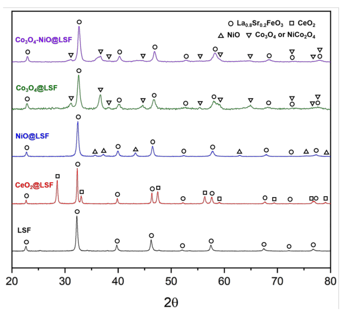
The XRD patterns of synthesized La0.75Sr0.25FeO3 (LSF), CeO2@LSF, NiO@LSF, Co3O4@LSF, and Co3O4-NiO@LSF are shown in Figure 2. The crystal phase of LSF matched the PDF card of La0.8Sr0.2FeO3 (PDF #: 00-035-1480), indicating the formation of a fully oxidized orthorhombic perovskite structure. Other core–shell structured samples also showed the same perovskite phase with each metal oxide phases, i.e., CeO2 (PDF #: 01-080-8533), NiO (PDF #: 00-047-1049), Co3O4 (PDF #: 00-009-0418), and NiCo2O4 (PDF #: 01-073-1702). These observations indicated pure oxygen carriers with the intended phases had been synthesized successfully.
ICP-MS and XPS were carried out to determine the atomic compositions of metal cations in the bulk phase and surface of prepared oxygen carriers, respectively. ICP-MS and XPS data are summarized in Table 1, in which cation compositions of metal oxide and perovskite are referred to ‘cations of metal oxide’ and ‘cations of perovskite’. For example, in CeO2@LSF, ‘cations of metal oxide’ only considers the composition of Ce cation while ‘cations of perovskite’ includes the remaining cations, which consists of the perovskite phase, La, Sr, and Fe. The cation compositions of metal oxide as determined by the ICP-MS matched theoretical value in the bulk phase particle, i.e., 0.33 for Ce in CeO2@LSF, 0.33 for Ni in NiO@LSF, 0.6 for Co in Co3O4@LSF, and 0.5 for Co+Ni in Co3O4-NiO@LSF.
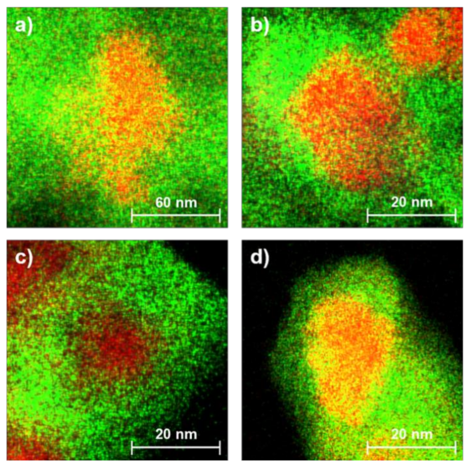
While the result of ICP-MS represented the bulk phase composition, XPS analysis showed the cation composition of the surface side. When ICP-MS and XPS data were compared, molar compositions of metal oxides determined by XPS were around half of the bulk composition determined by ICP-MS. This indicated that metal oxide phases were largely confined to cores and the perovskite structures were mainly presented on the particle surfaces, as has been previously reported for the same preparative procedure [32,35]. HAADF-STEM mapping in Figure 3 and Figure 4 confirmed the core–shell structure of particles with a metal oxide core and perovskite shell. In the STEM mapping, metal oxide cores with 20–40 nm were clearly encapsulated by perovskite shells.

3.2. RWGS-CL Performance of the Oxygen Carriers

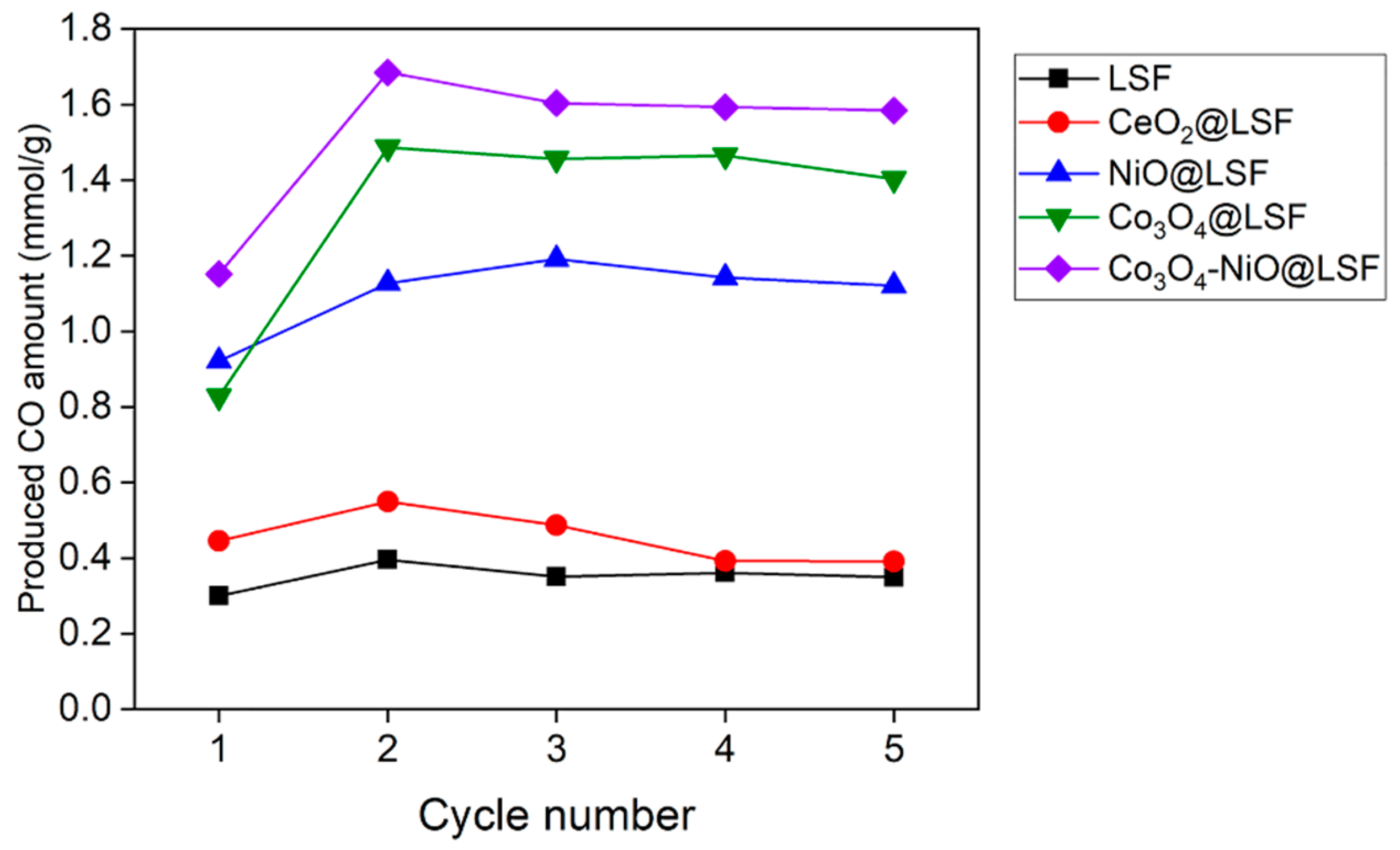
To observe the effect of core–shell structured particles, the amounts of CO produced by the prepared oxygen carriers during the oxidation step are shown in Figure 5. As shown in the figure, NiO@LSF, Co3O4@LSF, and Co3O4-NiO@LSF produced more CO than LSF, whereas LSF and CeO2@LSF produced similar amounts (0.35–0.55 mmol/gOC), which could be due to the low oxygen storage capacity of CeO2. Unlike other metal oxide cores, CeO2 cannot be fully reduced at the operating condition then the amount of reducible oxygen of CeO2@LSF is lower than others. On the other hand, Co3O4 and NiO-based oxygen carriers recorded about 3-fold higher production amounts of CO after the 2nd cycle (1.15 mmol/gOC for NiO@LSF, 1.45 mmol/gOC for Co3O4@LSF, and 1.6 mmol/gOC for Co3O4-NiO@LSF). For successful RWGS-CL cycling, particles should have a high ability to form oxygen defective active sites when exposed to hydrogen atmosphere and these oxygen-defective sites should be properly consumed by CO2 sourced oxygen during the CO2 oxidation step. Therefore, it can be inferred that the NiO@LSF, Co3O4@LSF, and Co3O4-NiO@LSF have the higher oxygen mobility than simple perovskite catalysts.

3.3. Temperature-Programmed Processes

In order to get more insights, temperature-programmed processes were performed on the prepared oxygen carriers. Firstly, H2-TPR measurements were obtained for LSF and other core–shell structured oxygen carriers to observe temperatures at which oxygen defects are first formed during the hydrogen reduction step. Additionally, the amount of the oxygen defect formed by H2 was measured.
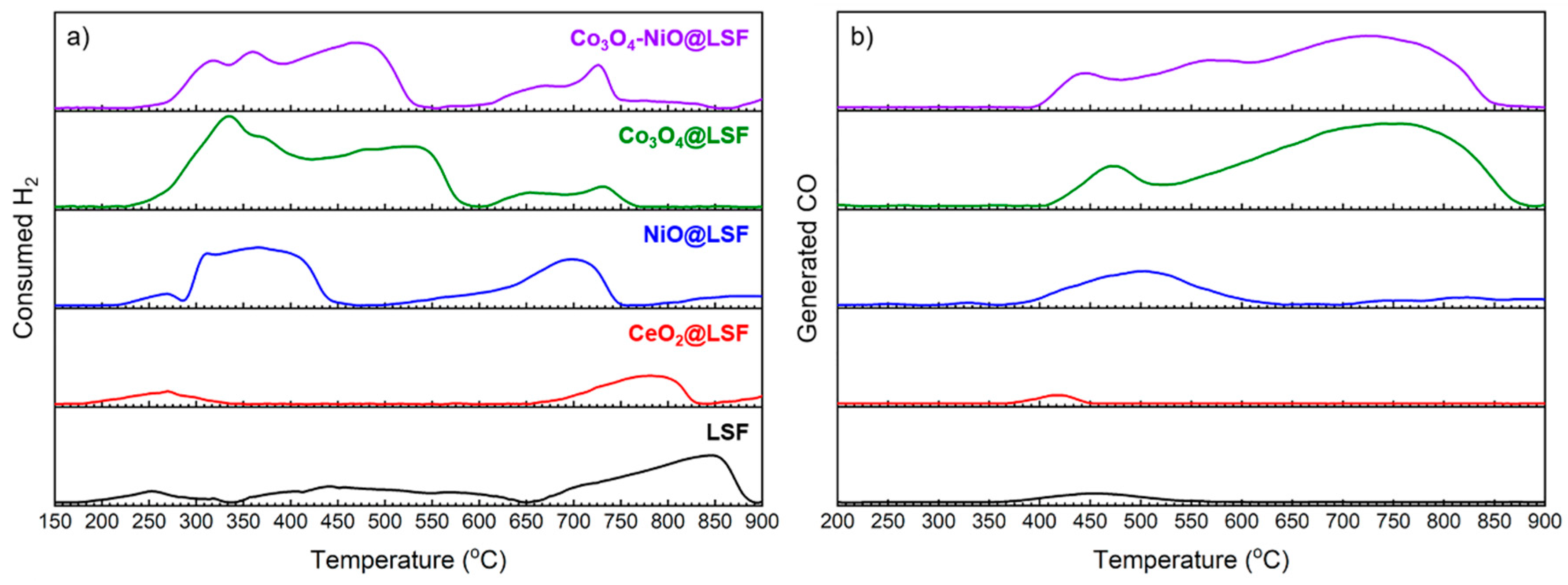
Amounts of H2 consumed as determined by H2-TPR measurements are presented in Figure 6a and Table 2. The results obtained showed that overall hydrogen consumptions by LSF and CeO2@LSF were lower than those of NiO@LSF, Co3O4@LSF, and Co3O4-NiO@LSF as expected from Figure 5. Furthermore, H2 was mainly consumed at a temperature higher than 600 °C for LSF and CeO2@LSF. On the other hand, the other three carriers consumed much more hydrogen even at temperatures lower than 600 °C, which means that these oxygen carriers have a strong tendency to generate an oxygen defect when reacted with H2. Co3O4@LSF consumed the most hydrogen at temperatures lower than 600 °C and was followed by Co3O4-NiO@LSF. However, hydrogen consumptions at temperatures up to 600 °C did not fully follow the amounts of CO generated as described in Figure 5. For instance, Co3O4-NiO@LSF presented the highest amount of generated CO during redox cycles although it consumed less hydrogen than Co3O4@LSF at temperatures lower than 600 °C. This is because the consumption of the oxygen defect by CO2 should also be considered to explain the amount of CO production of the oxygen carrier.
To observe oxygen defect consumptions during the CO2 oxidation step, CO2-TPO measurements were carried out on reduced oxygen carriers. Amounts of CO generation during CO2-TPO measurement are presented in Figure 6b and Table 2. Based on considerations of RWGS-CL at an operating temperature of 600 °C, CO formation up to 600 °C was explained better with the trend of RWGS-CL in Figure 5. Co3O4-NiO@LSF generated the highest amount of CO at temperatures up to 600 °C in CO2-TPO measurements, which explained why it produced the most CO in the isothermal experiment in Figure 5. Although Co3O4@LSF showed the highest amount of CO production at temperatures up to 900 °C, more than two-thirds of this CO was generated between 600 and 900 °C. CO generation of NiO@LSF was lower than that of Co3O4-NiO@LSF and Co3O4@LSF, and more than 80% of oxygen defects in NiO@LSF were consumed by CO2 under 600 °C (0–600 °C: 1.27 mmol/gOC, 600–900 °C: 0.31 mmol/gOC). It appears that Co3O4-NiO@LSF is an optimized composition as it had the advantages of Co3O4 and NiO at the same time; the effective CO generation of Co3O4@LSF and the relatively low oxidation temperature of NiO@LSF. Therefore, Co3O4-NiO was chosen as the optimum metal oxide core for RWGS-CL.

3.4. Long-Term Stability Test

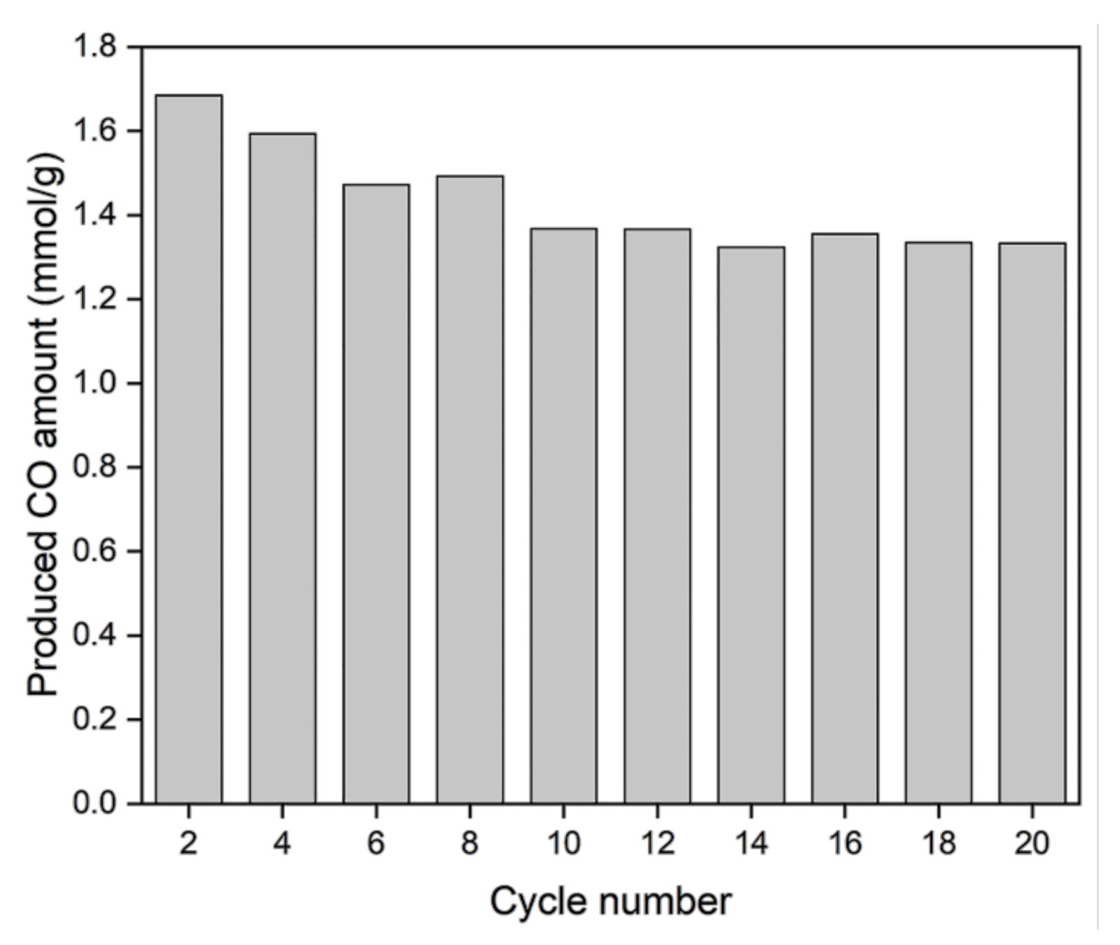
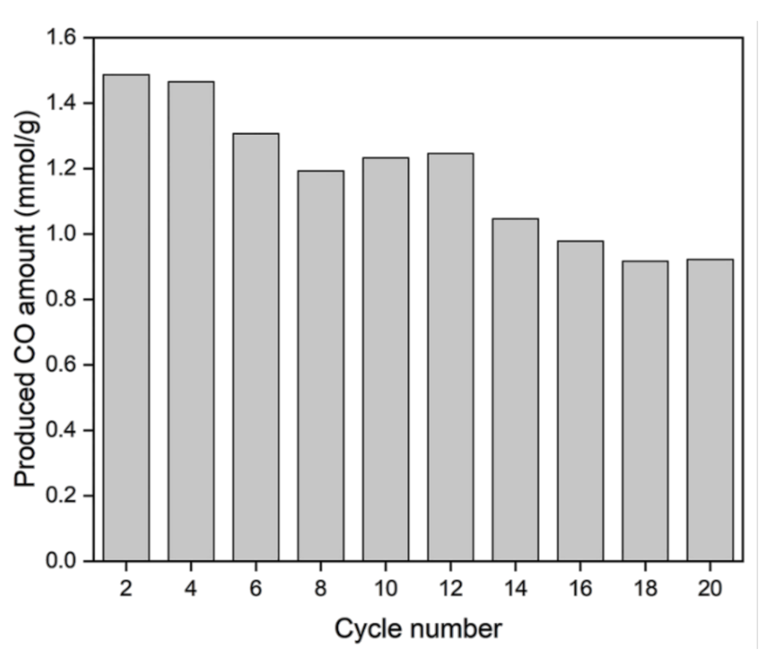
Figure 7 portrays the result of the long-term stability test for the Co3O4-NiO@LSF oxygen carrier. As shown by the figure, the amount of CO produced by Co3O4-NiO@LSF gradually decreased until the 10th cycle and then remained constant from the 10th to the 20th cycles. More specifically, the amounts of CO generated during the 2nd, 10th, and 20th cycles were 1.68, 1.37, and 1.33 mmol/gOC, respectively. According to the result, Co3O4-NiO@LSF maintained 97.6% of CO production at the 20th cycle as that observed at the 10th cycle, which indicated that the productivity of CO on this sample was stabilized after the 10th cycle. Furthermore, even after 20 redox cycles, Co3O4-NiO@LSF showed clearly higher performance than the values seen during five redox cycles of LSF, CeO2@LSF, and NiO@LSF (Figure 5). For Co3O4@LSF (Figure 8), amounts of CO generated at the 2nd, 10th, and 20th cycles were 1.49, 1.23, and 0.92 mmol/gOC, respectively, which presents the gradual decrease of the activity of oxygen carrier. This is because Co3O4@LSF requires a higher temperature than 600 °C to be fully oxidized by CO2 (Figure 6b). From the long-term stability test, it was found that the Co3O4-NiO@LSF sample showed not only the highest CO productivity among all samples but also the highest stability during the multiple redox cycles.
Table 3 shows the comparison between the core–shell structured oxygen carrier with others in terms of CO production. Most previous research reported lower CO production than the core–shell structured oxygen carrier. Although one research that used Co-based perovskite showed a higher CO production [36], the operating temperature of Co-based perovskite (850 °C) is much higher than the present research (600 °C). From this comparison, it was confirmed that Co3O4-NiO@LSF was sufficiently competitive for CO production at the relatively low temperature (600 °C).

4. Conclusions

This paper investigated the potential use of metal oxide core–perovskite shell oxygen carriers in a reverse water–gas shift chemical looping (RWGS-CL) process. La0.75Sr0.25FeO3 (LSF) and MeOx@LSF (MeOx: CeO2, NiO, Co3O4, and Co3O4-NiO) oxygen carriers were prepared and subjected to RWGS-CL experiments. Cyclic RWGS-CL experiments showed that NiO@LSF, Co3O4@LSF, and Co3O4-NiO@LSF generated more CO than LSF. CeO2@LSF showed a similar CO amount with LSF due to the relatively low reducible oxygen capacity of CeO2 (0.35–0.55 mmol/gOC) as compared with those of Co3O4 and NiO-based oxygen carriers (1.15–1.6 mmol/gOC). Temperature-programmed redox reactions were conducted to determine the oxygen capacity and mobility in the reduction and oxidation steps. These analyses revealed that the core–shell structured oxygen carriers effectively formed oxygen defects and consumed at relatively low temperature. Co3O4-NiO@LSF was chosen as the optimum oxygen carrier because it possessed the advantages of Co3O4@LSF and NiO@LSF. Moreover, the amount of produced CO was stably maintained for 20 cycles on Co3O4-NiO@LSF.

Author Contributions

Conceptualization, M.L. and D.K.; Data curation, Y.K. and H.S.L.; Investigation, Y.K. and A.J.; Methodology, M.L. and A.J.; Supervision, D.K. and J.W.L.; Validation, M.L. and Y.K.; Writing—original draft, M.L.; Writing—review and editing, H.S.L., D.K. and J.W.L. All authors have read and agreed to the published version of the manuscript.

Funding

This research was supported by the UK-Korea Joint Research Program through NRF grants (NRF-2019M2A7A1001773) funded by the Ministry of Science, ICT and Future Planning and the Basic Science Research Program through the National Research Foundation of Korea (NRF) funded by the Ministry of Education (2020R1I1A3051997).

Conflicts of Interest

The authors declare no conflict of interest.

References

  1. Byeon, A.; Baik, S.; Lee, J.W. Enhanced electrocatalytic reduction of oxygen at CO2-derived FeNB-doped porous carbon. J. CO2 Util. 2018, 26, 28–35. [Google Scholar] [CrossRef]
  2. Tucki, K.; Orynycz, O.; Mitoraj-Wojtanek, M. Perspectives for Mitigation of CO2 Emission due to Development of Electromobility in Several Countries. Energies 2020, 13, 4127. [Google Scholar] [CrossRef]
  3. Qiu, H.-H.; Liu, L.-G. A Study on the Evolution of Carbon Capture and Storage Technology Based on Knowledge Mapping. Energies 2018, 11, 1103. [Google Scholar] [CrossRef] [Green Version]
  4. Olivier, J.G.J.; Janssens-Maenhout, G.; Muntean, M.; Peters, J.A.H.W. Trends in Global CO2 Emissions; PBL Netherlands Environmental Assessment Agency: The Hague, The Netherlands, 2015. [Google Scholar]
  5. Kim, H.J.; Chun, Y.N. Conversion of Biogas to Renewable Energy by Microwave Reforming. Energies 2020, 13, 4093. [Google Scholar] [CrossRef]
  6. Olabi, A.G. Renewable energy and energy storage systems. Energy 2017, 136, 1–6. [Google Scholar] [CrossRef]
  7. Deshmukh, M.K.; Deshmukh, S.S. Modeling of hybrid renewable energy systems. Renew. Sustain. Energy Rev. 2008, 12, 235–249. [Google Scholar] [CrossRef]
  8. Hare, B.J.; Maiti, D.; Ramani, S.; Ramos, A.E.; Bhethanabotla, V.R.; Kuhn, J.N. Thermochemical conversion of carbon dioxide by reverse water-gas shift chemical looping using supported perovskite oxides. Catal. Today 2019, 323, 225–232. [Google Scholar] [CrossRef]
  9. Kim, Y.K.; Kim, G.M.; Lee, J.W. Highly porous N-doped carbons impregnated with sodium for efficient CO2 capture. J. Mater. Chem. A 2015, 3, 10919–10927. [Google Scholar] [CrossRef]
  10. Siefert, N.S.; Narburgh, S.; Chen, Y. Comprehensive Exergy Analysis of Three IGCC Power Plant Configurations with CO2 Capture. Energies 2016, 9, 669. [Google Scholar] [CrossRef] [Green Version]
  11. Daza, Y.A.; Maiti, D.; Kent, R.A.; Bhethanabotla, V.R.; Kuhn, J.N. Isothermal reverse water gas shift chemical looping on La0.75Sr0.25Co(1−Y)FeYO3 perovskite-type oxides. Catal. Today 2015, 258, 691–698. [Google Scholar] [CrossRef]
  12. Leung, D.Y.C.; Caramanna, G.; Maroto-Valer, M.M. An overview of current status of carbon dioxide capture and storage technologies. Renew. Sustain. Energy Rev. 2014, 39, 426–443. [Google Scholar] [CrossRef] [Green Version]
  13. McDaniel, A.H.; Miller, E.C.; Arifin, D.; Ambrosini, A.; Coker, E.N.; O’Hayre, R.; Chueh, W.C.; Tong, J. Sr- and Mn-doped LaAlO3−δ for solar thermochemical H2 and CO production. Energy Environ. Sci. 2013, 6, 2424–2428. [Google Scholar] [CrossRef]
  14. Kang, D.; Lim, H.S.; Lee, M.; Lee, J.W. Syngas production on a Ni-enhanced Fe2O3/Al2O3 oxygen carrier via chemical looping partial oxidation with dry reforming of methane. Appl. Energy 2018, 211, 174–186. [Google Scholar] [CrossRef]
  15. Kim, Y.; Lim, H.S.; Lee, M.; Lee, J.W. Ni-Fe-Al mixed oxide for combined dry reforming and decomposition of methane with CO2 utilization. Catal. Today 2020. [Google Scholar] [CrossRef]
  16. Tuci, G.; Filippi, J.; Rossin, A.; Luconi, L.; Pham-Huu, C.; Yakhvarov, D.; Vizza, F.; Giambastiani, G. CO2 Electrochemical Reduction by Exohedral N-Pyridine Decorated Metal-Free Carbon Nanotubes. Energies 2020, 13, 2703. [Google Scholar] [CrossRef]
  17. Kang, D.; Lee, M.; Lim, H.S.; Lee, J.W. Chemical looping partial oxidation of methane with CO2 utilization on the ceria-enhanced mesoporous Fe2O3 oxygen carrier. Fuel 2018, 215, 787–798. [Google Scholar] [CrossRef]
  18. Wang, W.; Wang, S.; Ma, X.; Gong, J. Recent advances in catalytic hydrogenation of carbon dioxide. Chem. Soc. Rev. 2011, 40, 3703–3727. [Google Scholar] [CrossRef] [Green Version]
  19. Porosoff, M.D.; Yan, B.; Chen, J.G. Catalytic reduction of CO2 by H2 for synthesis of CO, methanol and hydrocarbons: Challenges and opportunities. Energy Environ. Sci. 2016, 9, 62–73. [Google Scholar] [CrossRef]
  20. Herron, J.A.; Kim, J.; Upadhye, A.A.; Huber, G.W.; Maravelias, C.T. A general framework for the assessment of solar fuel technologies. Energy Environ. Sci. 2015, 8, 126–157. [Google Scholar] [CrossRef]
  21. Chueh, W.C.; Falter, C.; Abbott, M.; Scipio, D.; Furler, P.; Haile, S.M.; Steinfeld, A. High-Flux Solar-Driven Thermochemical Dissociation of CO2 and H2O Using Nonstoichiometric Ceria. Science 2010, 330, 1797. [Google Scholar] [CrossRef] [Green Version]
  22. Hare, B.J.; Maiti, D.; Daza, Y.A.; Bhethanabotla, V.R.; Kuhn, J.N. Enhanced CO2 Conversion to CO by Silica-Supported Perovskite Oxides at Low Temperatures. ACS Catal. 2018, 8, 3021–3029. [Google Scholar] [CrossRef]
  23. Yang, X.; Su, X.; Chen, X.; Duan, H.; Liang, B.; Liu, Q.; Liu, X.; Ren, Y.; Huang, Y.; Zhang, T. Promotion effects of potassium on the activity and selectivity of Pt/zeolite catalysts for reverse water gas shift reaction. Appl. Catal. B Environ. 2017, 216, 95–105. [Google Scholar] [CrossRef]
  24. Haribal, V.P.; Wang, X.; Dudek, R.; Paulus, C.; Turk, B.; Gupta, R.; Li, F. Modified Ceria for “Low-Temperature” CO2 Utilization: A Chemical Looping Route to Exploit Industrial Waste Heat. Adv. Energy Mater. 2019, 9, 1901963. [Google Scholar] [CrossRef]
  25. Maiti, D.; Hare, B.J.; Daza, Y.A.; Ramos, A.E.; Kuhn, J.N.; Bhethanabotla, V.R. Earth abundant perovskite oxides for low temperature CO2 conversion. Energy Environ. Sci. 2018, 11, 648–659. [Google Scholar] [CrossRef]
  26. Ma, L.; Qiu, Y.; Li, M.; Cui, D.; Zhang, S.; Zeng, D.; Xiao, R. Spinel-Structured Ternary Ferrites as Effective Agents for Chemical Looping CO2 Splitting. Ind. Eng. Chem. Res. 2020, 59, 6924–6930. [Google Scholar] [CrossRef]
  27. Wenzel, M.; Rihko-Struckmann, L.; Sundmacher, K. Thermodynamic analysis and optimization of RWGS processes for solar syngas production from CO2. Aiche J. 2017, 63, 15–22. [Google Scholar] [CrossRef] [Green Version]
  28. Wenzel, M.; Aditya Dharanipragada, N.V.R.; Galvita, V.V.; Poelman, H.; Marin, G.B.; Rihko-Struckmann, L.; Sundmacher, K. CO production from CO2 via reverse water–gas shift reaction performed in a chemical looping mode: Kinetics on modified iron oxide. J. CO2 Util. 2017, 17, 60–68. [Google Scholar] [CrossRef] [Green Version]
  29. Huang, Z.; Deng, Z.; Chen, D.; Wei, G.; He, F.; Zhao, K.; Zheng, A.; Zhao, Z.; Li, H. Exploration of Reaction Mechanisms on Hydrogen Production through Chemical Looping Steam Reforming Using NiFe2O4 Oxygen Carrier. ACS Sustain. Chem. Eng. 2019, 7, 11621–11632. [Google Scholar] [CrossRef]
  30. Lim, H.S.; Lee, M.; Kang, D.; Lee, J.W. Role of transition metal in perovskites for enhancing selectivity of methane to syngas. Int. J. Hydrog. Energy 2018, 43, 20580–20590. [Google Scholar] [CrossRef]
  31. Lee, M.; Lim, H.S.; Kim, Y.; Lee, J.W. Enhancement of highly-concentrated hydrogen productivity in chemical looping steam methane reforming using Fe-substituted LaCoO3. Energy Convers. Manag. 2020, 207, 112507. [Google Scholar] [CrossRef]
  32. Neal, L.M.; Shafiefarhood, A.; Li, F. Dynamic Methane Partial Oxidation Using a Fe2O3@La0.8Sr0.2FeO3-δ Core–Shell Redox Catalyst in the Absence of Gaseous Oxygen. ACS Catal. 2014, 4, 3560–3569. [Google Scholar] [CrossRef]
  33. Shafiefarhood, A.; Galinsky, N.; Huang, Y.; Chen, Y.; Li, F. Fe2O3@LaxSr1−xFeO3 Core–Shell Redox Catalyst for Methane Partial Oxidation. ChemCatChem 2014, 6, 790–799. [Google Scholar] [CrossRef]
  34. Neal, L.; Shafiefarhood, A.; Li, F. Effect of core and shell compositions on MeOx@LaySr1−yFeO3 Core–Shell redox catalysts for chemical looping reforming of methane. Appl. Energy 2015, 157, 391–398. [Google Scholar] [CrossRef]
  35. Lim, H.S.; Kang, D.; Lee, J.W. Phase transition of Fe2O3–NiO to NiFe2O4 in perovskite catalytic particles for enhanced methane chemical looping reforming-decomposition with CO2 conversion. Appl. Catal. B Environ. 2017, 202, 175–183. [Google Scholar] [CrossRef]
  36. Daza, Y.A.; Kent, R.A.; Yung, M.M.; Kuhn, J.N. Carbon Dioxide Conversion by Reverse Water–Gas Shift Chemical Looping on Perovskite-Type Oxides. Ind. Eng. Chem. Res. 2014, 53, 5828–5837. [Google Scholar] [CrossRef]
  37. Rihko-Struckmann, L.K.; Datta, P.; Wenzel, M.; Sundmacher, K.; Dharanipragada, N.V.R.A.; Poelman, H.; Galvita, V.V.; Marin, G.B. Hydrogen and Carbon Monoxide Production by Chemical Looping over Iron-Aluminium Oxides. Energy Technol. 2016, 4, 304–313. [Google Scholar] [CrossRef]
  38. Galvita, V.V.; Poelman, H.; Bliznuk, V.; Detavernier, C.; Marin, G.B. CeO2-Modified Fe2O3 for CO2 Utilization via Chemical Looping. Ind. Eng. Chem. Res. 2013, 52, 8416–8426. [Google Scholar] [CrossRef]
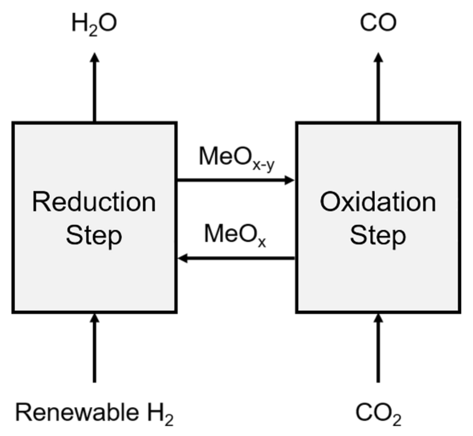
Figure 1. Schematic of the reverse water–gas shift chemical looping (RWGS-CL) process.
Energies 13 05324 g001
Figure 2. XRD spectra of the oxygen carriers.
Energies 13 05324 g002
Figure 3. High-angle annular dark-field scanning transmission electron microscopy (HAADF-STEM) mapping images of the prepared oxygen carriers. CeO2@LSF (a), NiO@LSF (b), Co3O4@LSF (c), and Co3O4-NiO@LSF (d). Green = La, Sr, and Fe; (Red = each core metal (Co in (d)), Yellow = Ni in (d)).
Energies 13 05324 g003
Figure 4. HAADF-STEM mapping image of La0.75Sr0.25FeO3.
Energies 13 05324 g004
Figure 5. Amounts of CO produced by the oxygen carriers during the oxidation step.
Energies 13 05324 g005
Figure 6. Results of H2-TPR (a) and CO2-TPO (b) measurements.
Energies 13 05324 g006
Figure 7. Cyclic performance of Co3O4-NiO@LSF during the long-term stability test.
Energies 13 05324 g007
Figure 8. Cyclic performance of Co3O4@LSF during the long-term stability test.
Energies 13 05324 g008
Table 1. Cation compositions measured by inductively coupled plasma mass spectroscopy (ICP-MS) and XPS.
Oxygen CarrierCations of Metal OxideCations of Perovskite
ICP-MSXPSICP-MSXPS
CeO2@LSF0.310.170.690.83
NiO@LSF0.310.130.690.87
Co3O4@LSF0.580.230.420.77
Co3O4-NiO@LSF0.530.290.470.71
Table 2. Results of H2-TPR and CO2-TPO measurements.
Oxygen CarrierConsumed H2 (mmol/gOC)Generated CO (mmol/gOC)
Until 600 °CUntil 900 °CUntil 600 °CUntil 900 °C
LSF1.754.720.280.29
CeO2@LSF0.471.860.110.11
NiO@LSF3.796.141.271.58
Co3O4@LSF8.189.061.486.26
Co3O4-NiO@LSF5.687.421.895.71
Table 3. Comparison for CO productions with various oxygen carriers.
Oxygen CarrierReferenceTemp. (°C)Produced CO (mmol/gOC)
La0.75Sr0.25CoO3[36]8504.03
Fe2O3-Ce0.5Zr0.5O2[28]8001.00 *
Fe2O3-Al2O3[37]7500.84 *
CeO2-Fe2O3[38]6001.01 *
Co3O4-NiO@LSFThis study6001.33
* Estimated from experimental results.