Abstract
In this paper, we propose an optimized power distribution method for hybrid electric energy storage systems for electric vehicles (EVs). The hybrid energy storage system (HESS) uses two isolated soft-switching symmetrical half-bridge bidirectional converters connected to the battery and supercapacitor (SC) as a composite structure of the protection structure. The bidirectional converter can precisely control the charge and discharge of the SC and battery. Spiral wound SCs with mesoporous carbon electrodes are used as the energy storage units of EVs. Under the 1050 operating conditions of the EV driving cycle, the SC acts as a “peak load transfer” with a charge and discharge current of 2isc~3ibat. An improved energy allocation strategy under state of charge (SOC) control is proposed, that enables SC to charge and discharge with a peak current of approximately 4ibat. Compared with the pure battery mode, the acceleration performance of the EV is improved by approximately 50%, and the energy loss is reduced by approximately 69%. This strategy accommodates different types of load curves, and helps improve the energy utilization rate and reduce the battery aging effect.
1. Introduction
In recent years, energy shortages and environmental degradation have attracted increasing attention [1,2,3,4,5,6]. Increasing car ownership has led to an increase in pollution from automobile exhaust emissions, thereby forcing the acceleration of energy transformation in the automotive industry. As a new type of transportation, electric vehicles (EVs) have great advantages in energy saving, emission reduction and reduction of fossil fuel dependence, which has greatly promoted their development.
The power supply system is the core part of the EV and directly affects the overall performance of the vehicle [7,8,9,10] and currently, the power supply problem of electric vehicles is a major obstacle to the development of EVs [11]. To promote and use EVs more widely, electric vehicles need higher specific energy, higher specific power, longer cycle life of energy storage system and higher charging efficiency [12,13,14,15,16].
Conventional EV energy storage systems are battery-based storage devices, which have large deficiencies and limitations [17,18,19,20]. First, the power density of the battery is low, thereby it cannot meet the peak power demand of EVs under acceleration or climbing conditions. Although the power demand can be satisfied by increasing the number of battery cells, the EV load will be increased considerably. Second, in battery energy storage systems, frequent current changes generate additional heat, reducing efficiency and battery life.
Therefore, we herein study a hybrid energy storage system (HESS) comprising batteries and supercapacitors (SCs). As a new type of environmentally friendly energy storage device, SC has the advantages of high power density, high efficiency, fast response speed, and long cycle life that can improve energy utilization and dynamic performance to some extent [21,22,23,24,25,26].
The range of power required for operation under certain operating conditions (such as starting, acceleration, deceleration, stopping, and climbing) is wide. When the SC is directly connected to the battery, stabilizing the output voltage and controlling the energy distribution is difficult. In our research, we adopted the half-bridge of the control topology, wherein a bidirectional DC/DC converter connects the SC to the battery [27,28,29,30]. To enhance the discharge persistence of the battery current, the battery current is reduced to a minimum. The entire driving cycle strategy is employed to reduce the power loss in a given load curve. A discrete optimization design is used to improve the control effect of EVs.
This paper analyzes the deficiencies of the topology and control strategies of traditional HESSs, improves the previous topology, and proposes an optimized power allocation strategy based on the current control of EVs, thereby accurately predicting future power requirements. In addition, on the basis of current control, we herein add the SOC control of SCs based on the driving speed of EVs, thereby reducing the overcharge and overdischarge of the battery, improving the climbing performance of the EV, improving the energy utilization rate and reducing the battery aging effect [31,32,33,34,35,36,37].
2. Hybrid Energy Storage System
Energy storage devices can be divided into physical energy storage devices, chemical energy storage devices, and electromagnetic energy storage devices. Table 1 lists the main parameters of the common energy storage devices.

Table 1.
Main parameters of common energy storage.
Table 1 shows that a single energy storage device cannot unify power density and energy density, and cannot meet the complex and variable power demand of EVs. Combining the advantages of batteries and SCs, it is proposed that batteries and SCs be used as composite energy sources to meet the needs of EV power supply changes. The high energy density of the battery guarantees EV mileage for one charge. SCs can provide instantaneous high current output to meet the peak power (such as for acceleration and climbing) required by EVs, thus ensuring dynamic performance. When the EV decelerates or degrades, the power system is in an energy feedback state; thus, the SC can more efficiently and quickly absorb feedback energy, improve the energy efficiency of the system, and protect the battery from heavy currents. There are four common structures of HESS composed of two energy storage devices and one load device [38,39,40,41]:
(1) The SC, battery and load are directly connected in parallel, as shown in Figure 1a. This connection is low cost and fast response, but it also has several limitations: such as the capacity of the energy storage system cannot be fully utilized, and the power allocation is not controlled; the voltage of the SC is not controlled, and it depends on the SOC of the battery, which will affect the optimal utilization of SC.
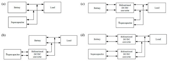
Figure 1.
(a) Direct parallel structure; (b) Structure of SC control; (c) Structure of battery control; (d) Structure of two power supply control.
(2) The SC control structure, as shown in Figure 1b. The SC is connected to the DC/DC bidirectional converter, and the battery is directly connected to the DC bus. This structure can lead to the capacity of the SC being fully utilized, and this is advantageous to the high-power throughput capacity of the SC. However, the charging and discharging and the power of the battery cannot be effectively controlled.
(3) The battery control structure, as shown in Figure 1c. The power of the battery can be controlled, and the charging and discharging current of the battery can be optimized that can prolong the service life of the battery. The SC can achieve a fast response speed when the peak power output changes, but obtaining a stable voltage is difficult, resulting in poor system stability.
(4) The dual-power control structure, as shown in Figure 1d. The structure can provide flexible voltage control, and can better allocate power to the battery and the SC. The battery can also prolong the service life, and its energy can be fully utilized. Bidirectional DC/DC can be used for an energy management system with a more flexible configuration. However the existence of bidirectional DC/DC will increase the cost and loss of the system, as well as increase the complexity of the system structure and the mass of EVs [42,43,44].
Currently, SC control structures are widely used in EV composite power supply systems. In this study, a new power allocation strategy is required to accurately control the charging and discharging of the battery and SC. Figure 1d shows a schematic of the structure. In this study, the bidirectional DC/DC converter adopts half-bridge topology structure. The principle of the bidirectional DC/DC converter in HESS of EVs. When the system is discharged, the bidirectional DC/DC controller operates in the Boost mode, and the energy flows from the low-voltage side to the high-voltage side; when the system is in charge, the bidirectional DC/DC controller operates in the Buck mode, and the energy flows from the high-voltage side to the low-voltage side.
A supercapacitor is a type of energy storage device, that stores electric energy converted from various clean energy sources. It is conventionally divided into two types: stacked and wound. Electrode materials are important factors affecting the energy storage characteristics of SCs. Ordered mesoporous carbon materials not only have the characteristics of uniform pore size distribution, large pore volume and high specific surface area, but also have the advantages good chemical inertness, strength, electrical conductivity and thermal stability. In this study, a spiral wound SC with ordered mesoporous carbon electrodes was used. Figure 2 shows the diagram of the SC structure.
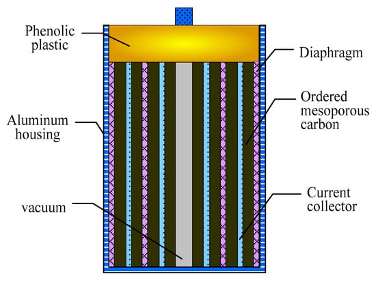
Figure 2.
SC structure diagram.
Figure 3 shows the electrochemical properties of the ordered mesoporous carbon (OMC) electrode. According to the X-ray diffraction (XRD) pattern of the ordered mesoporous carbon, it is known that no impurity peak appears, the full width at half maximum is large, and the degree of crystallization is small, indicating it to be a good electrode material. According to the SEM (scanning electron microscope) image of the ordered mesoporous carbon, the basic unit structure is uniform in size. According to the transmission electron microscope (TEM) image of the ordered mesoporous carbon, the pore structure is arranged in order and the conductivity is strong. The charge and discharge curves of the electrode material at 5 mA show good linearity, the self-discharge current is relatively small, and there is no obvious voltage drop at the initial discharge, indicating that the electrode material has a small internal resistance and ideal capacitance performance; moreover, it is suitable as an energy storage system unit for EVs.
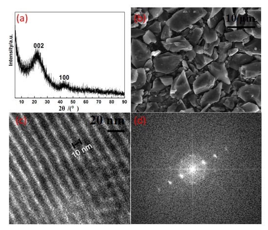
Figure 3.
Electrochemical properties: (a) =XRD spectrum of the synthesized OMC; (b) SEM photograph of the OMC; (c) and (d) =TEM photographs of the OMC.
To detect the characteristics of SCs, constant current charge and discharge experiments were carried out on the SC cells used herein. The charge and discharge voltage range was set to −1.0–0 V, and the charge and discharge currents were 5, 8 and 10 mA. The single charge and discharge curves have good reversibility, and the two sides of the curve are basically symmetrical. The initial voltage has no significant voltage drop and has ideal capacitive characteristics. As shown in Figure 4b, the half-arc of the high-frequency region is small, indicating that the charge transfer resistance at the interface between the electrode and the electrolyte is small. In the intermediate-frequency region, the slope is close to 45°, which is related to the charge transfer impedance; the straight line in the low-frequency region is similar to the vertical line, demonstrating good capacitance characteristics. As shown in Figure 4c, the curve shows a typical capacitance characteristic. The time constant (the product of capacitance and resistance) determines the steepness of the potential conversion. When the scanning direction changes, the electrode exhibits a fast current response and is rapid in a stable state, indicating that the internal resistance is small, the RC time constant is small, and it is suitable for high current. As shown in Figure 4d, as the number of cycles increases, the attenuation of capacitance weakens. In the initial stage of the cycle, the surface functional groups of the OMC will decompose, thereby consuming part of the capacitance. Second, as the number of cycles increases, the increase in the temperature of the capacitor will decrease the capacitance, causing a partial fragile hole to be broken. Simultaneously, the increase in temperature further exacerbates the decomposition of the surface functional groups. However, the overall fit is good, and it is suitable as an energy storage system unit for EVs.
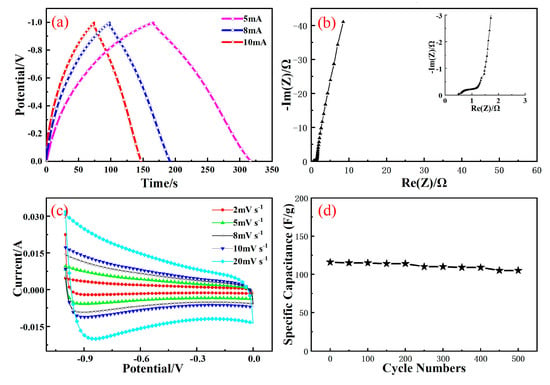
Figure 4.
Electrical performance test: (a) Charge–discharge curves; (b) Impedance characteristic curves; (c) CV curves; (d) Cycle performance curves.
Figure 5 shows the state of health (SOH) estimation during the supercapacitor cycle. When the number of cycles was less than 6000, the SOH of the supercapacitor was maintained above 80%, and the cycle performance was relatively good.
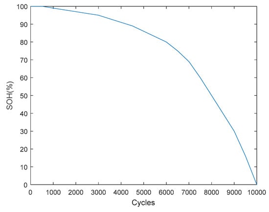
Figure 5.
SC cycle performance.
Currently, SC control structures are widely used in EV composite power systems. Based on the dual-power control structure, a new power allocation strategy is proposed to accurately control the charging and discharging of the battery and the SC. The DC converter used herein a composite converter with an isolated soft-switching symmetrical half-bridge bidirectional converter as a protection structure. The principle of bidirectional DC/DC converter in HESS of Ev is as follows: When the system is discharged, the bidirectional DC/DC controller works in the boost mode, and energy flows from the low-voltage side to the high-voltage side. When the system is charged, the bidirectional DC/DC controller operates in the buck mode, and energy flows from the high-voltage end to the low-voltage end. Figure 6 shows a device used in EV testing.
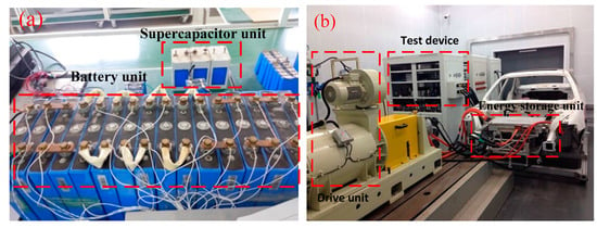
Figure 6.
Experimental test device: (a) Mixed energy storage unit; (b) Vehicle test device.
3. Typical Control Policy
The basic structure of the control strategy in the EV HESSs is shown in Figure 7. The DC/DC converter uses a composite converter with an isolated soft-switching symmetrical half-bridge bidirectional converter as a protection structure when extreme currents occur, as opposed to the non-isolated DC/DC converter used previously. In the event of a sudden increase in current, switching to an isolated converter is possible to avoid damage to the energy storage system due to direct electrical connections. Under normal operating conditions, the DC/DC converter operates in the boost mode during discharge and operates in the buck mode during energy feedback.
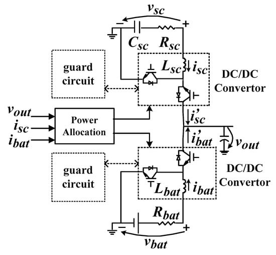
Figure 7.
Conventional control structure.
The power distribution method is as follows. When the EV is driven at a constant speed, the battery unit is separately powered in the HESS. At this time, the battery cells were discharged at a constant current. When the EV accelerates or climbs a hill, the remaining peak power is provided by the SC to meet the power demand. When the EV is decelerated, the feedback power generated by the brake is obtained by the battery, reducing energy waste. When the bus current changes abruptly, the battery unit maintains a constant current through the power distribution module, and the remaining peak current is absorbed and released by the SC.
The driving cycle test was performed under the working condition of 1015 as shown in Figure 8. The simulation results of power distribution are shown in Figure 9. It can be concluded that the operating current of the SC is relatively large under this control mode, and isc is 2–3 times that of the ibat. The SC acts as a “peak load transfer” to help extend battery life. This control method can effectively play the role of SC’s “peak clipping and valley filling”, improve the energy utilization rate of the HESS, and limit the peak current of the battery unit to a safe range.
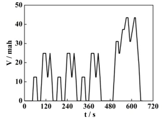
Figure 8.
1015 driving cycle.
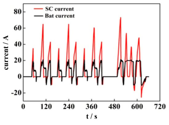
Figure 9.
Charge and discharge current distribution of supercapacitors and batteries under the traditional strategy.
As shown in Figure 10, the SOC of the SC demonstrated a large decline at the end of the EV driving cycle and at the lowest point, it dropped to 0.67. This causes the terminal voltage of the SOC of the SC to drop, thereby reducing the transmission efficiency of the DC/DC circuit.
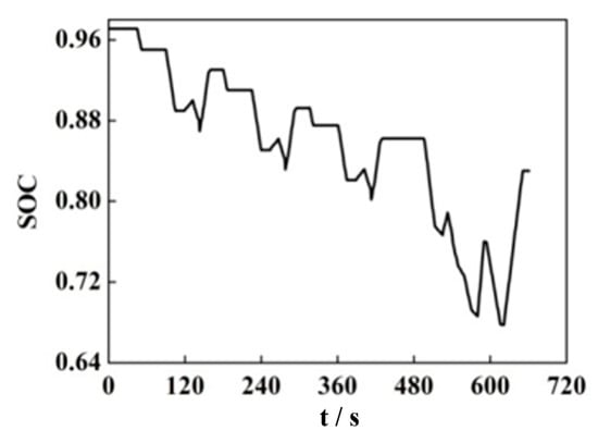
Figure 10.
SOC curve of supercapacitors in the typical strategy.
This phenomenon occurs owing to some frequent peak acceleration and deceleration during driving, which result in a large discharge current, but the feedback current is small. During the braking process, most feedback current is absorbed by the battery unit, and the SC cannot recover to a higher SOC value in a short time. In response to this drawback, the feedback object is replaced, and the control SC preferentially absorbs the feedback energy. However, this method allows the SC to charge in a short time. If the remaining large current is still absorbed by the battery, it will reduce the battery life and reduce the energy efficiency.
When an EV operates under extreme acceleration or emergency braking, the energy storage system needs to provide a large peak power or a large peak current. If it is through a non-isolated bidirectional DC/DC converter, direct electrical connections can cause significant damage to the energy storage system. When the peak current exceeds a certain threshold, the current in the DC converter passes through the isolated soft-switching symmetric half-bridge bidirectional converter that protects the safe operation of the energy storage system to some extent. Compared with a full-bridge bidirectional converter, the symmetrical half-bridge bidirectional converter is only half of the latter; therefore, the loss is small and the efficiency is high. The protection circuit topology is shown in Figure 11.
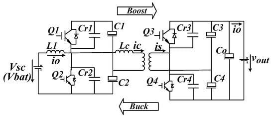
Figure 11.
Isolated soft-switching symmetric half-bridge bidirectional converter.
4. Improved SOC Control Strategy
Based on the disadvantages of the traditional control strategy, an improved control strategy is proposed herein based on the compound converter structure with an isolated soft-switching symmetric half-bridge two-way converter as the protection structure. As shown in Figure 12, speed and SC SOC control are added to the controller as influencing factors, thereby forming a four-dimensional space vector control strategy.
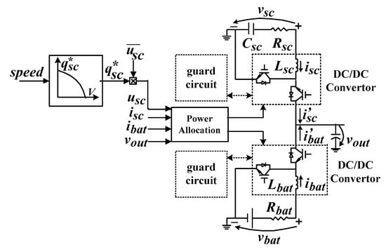
Figure 12.
SOC control structure.
According to the above discussion, the driving cycle has an important influence on the control effect. Therefore, the new strategy adjusts SC SOC to the optimal state by analyzing the relationship between SC SOC, speed and power demand. During the electric vehicle is running, the SC provides peak power and the battery provides average power. Considering the kinetic energy theorem, the following relationship can be obtained (excluding power losses):
Here, v is the current vehicle speed, vmax is the maximum vehicle speed, m is the vehicle total mass, c is the SC system capacitance, usc is the current voltage of the SC end, sc is the rated voltage of the SC, Pbat is the rated power of the battery, t0 is the time for battery to release energy, ubat is the battery nominal voltage, and ibat is the battery nominal current. From (1) and (2), the optimal SC SOC is given by:
where, q is the SOC of the ultracapacitor, and q* is the ideal SOC of the SC. To verify the performance of the optimized power distribution strategy, experimental tests were performed under different conditions. The results of the current distribution are shown in Figure 13. Unlike the traditional control strategy, the battery transfers charge to SC at a constant speed driving and stopping stage, and the current frequency is higher than that of the traditional control strategy. At the end of the acceleration process (380–500 s), the SC provides approximately four times higher ibat peak current than the conventional mode. Based on the comparison between traditional control strategy and the SOC control strategy, the SOC control strategy is concluded to be more conducive to EV acceleration performance. The SOC curve of the SC is shown in Figure 14.
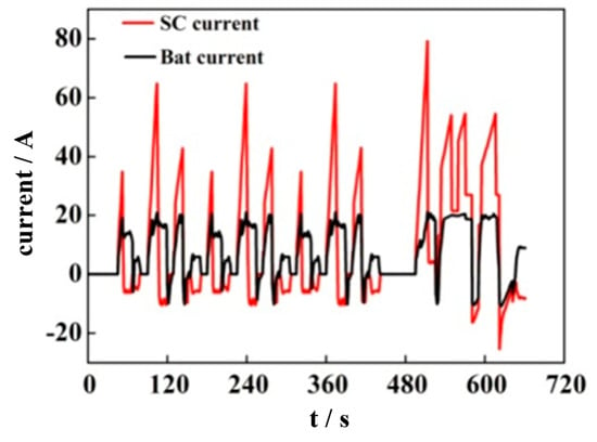
Figure 13.
Charge and discharge current distribution of supercapacitors and batteries under SOC control strategy.
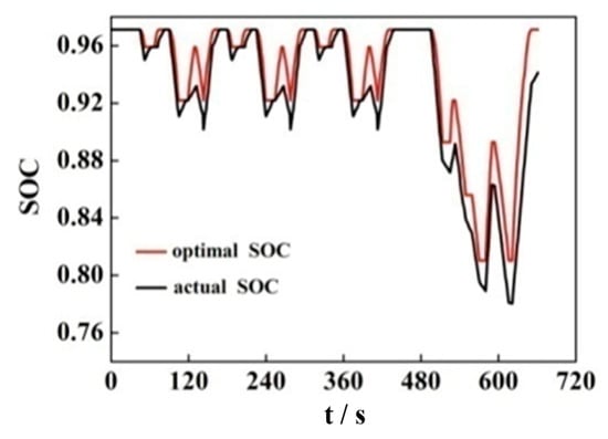
Figure 14.
SOC curve of the supercapacitor under the control strategy.
The SOC value of SC is 0.97. In the acceleration and braking stages, the actual SC SOC deviates from the expected value owing to the drastic change in SC charging and discharging current. The SC SOC approaches the optimal curve when EVs continue to operate. Compared with the SOC changes of SC shown in Figure 10, the SOC control strategy is more ideal. Under the optimized control strategy, the SOC of the SC has a small decrease, which can meet the energy output requirement.
The acceleration test of the system is shown in Figure 15a. The acceleration performance under the SOC control is approximately 50% higher than that of the pure battery, and approximately 25% higher than that of the conventional control. The energy loss test under EDUC, NYCC, 1050 and CSHVR is shown in Figure 15b. The energy loss under SOC control is approximately 4%, which is 23% lower than that of conventional control and 69% lower than that of the pure battery. The test parameters of the EV are shown in Table 2. The EV with the SOC control strategy has the shortest acceleration time and the lowest energy consumption. The SOC control strategy proposed herein is superior to the traditional control strategy in terms of acceleration performance and power distribution.

Figure 15.
Acceleration and power tests: (a) Acceleration tests; (b) Power tests.

Table 2.
Vehicle, Battery and SC Parameters.
5. Conclusions
The ordered mesoporous carbon electrode SC prepared herein exhibits good performance under high current conditions through charge and discharge experiments. Using the prepared SC, an optimized hybrid energy distribution method was proposed for the HESS. A hybrid converter with an isolated soft-switching symmetric half-bridge bidirectional converter is used as the protection structure to accurately control the charging/discharging of the SC and battery. Through the optimized power distribution method, the SC energy can be quickly supplemented when stopping and driving at a constant speed; this makes up for the shortcomings of the traditional control strategy. On the other hand, by controlling the SOC of the SC via the speed of EV enables the energy storage system to have better flexibility and adaptability, thereby enhancing the demand for the acceleration performance and energy variation of EVs. The experimental results demonstrate that the optimized SOC control strategy proposed herein can meet the peak power demand and energy loss, shorten the acceleration time of EVs but reduce the energy loss, improve the performance of EVs and extend the service life of the battery.
Author Contributions
Conceptualization, K.W. and L.L.; methodology, K.W.; software, W.W.; validation, W.W. and L.W.; formal analysis, K.W.; investigation, L.W.; resources, L.L.; data curation, L.L.; writing—original draft preparation, K.W.; writing—review and editing, W.W.; visualization, K.W.; supervision, K.W.; project administration, L.L.; funding acquisition, L.L. All authors have read and agree to the published version of the manuscript.
Funding
The work was supported by the Scientific Research Development Plan of Shandong Higher Education Institutions (No. J18KA316), the Development Plan of Shandong Province (No. 2019GGX104019), and Guangdong Basic and Applied Basic Research Foundation (2019A1515110706).
Conflicts of Interest
The authors declare no conflict of interest.
References
- Yuan, D.; Sun, M.; Zhao, M.; Tang, S.; Qi, J.; Zhang, X.; Wang, K.; Li, B. Persulfate promoted ZnIn2S4 visible light photocatalytic dye decomposition. Int. J. Electrochem. Sci. 2020, 15, 8761–8770. [Google Scholar] [CrossRef]
- Feng, X.; Zhang, Y.; Kang, L.; Wang, L.C.; Duan, C.X.; Yin, K.; Pang, J.B.; Wang, K. Integrated energy storage system based on triboelectric nanogenerator in electronic devices. Front. Chem. Sci. Eng. 2020. [Google Scholar] [CrossRef]
- Bu, C.Y.; Li, F.J.; Yin, K.; Pang, J.B.; Wang, L.C.; Wang, K. Research progress and prospect of triboelectric nanogenerators as self-powered human body sensors. ACS Appl. Electron. Mater. 2020, 2, 863–878. [Google Scholar] [CrossRef]
- Xia, G.T.; Huang, Y.N.; Li, F.J.; Wang, L.C.; Pang, J.B.; Li, L.W.; Wang, K. A thermally flexible and multi-site tactile sensor for remote 3D dynamic sensing imaging. Front. Chem. Sci. Eng. 2020. [Google Scholar] [CrossRef]
- Wang, K.; Li, L.W.; Xue, W.; Zhou, S.Z.; Lan, Y.; Zhang, H.W.; Sui, Z.Q. Electrodeposition synthesis of PANI/MnO2/Graphene composite materials and its electrochemical performance. Int. J. Electrochem. Sci. 2017, 12, 8306–8314. [Google Scholar]
- Yuan, D.L.; Zhang, C.; Tang, S.F.; Sun, M.T.; Zhang, Y.T.; Rao, Y.D.; Wang, Z.B.; Ke, J. Fe3+-sulfite complexation enhanced persulfate Fenton-like process for antibiotic degradation based on response surface optimization. Sci. Total Environ. 2020, 727, 138773. [Google Scholar] [CrossRef]
- Jiang, W.; Wu, X.; Zhao, H. Novel bifunctional converter-based supercapacitor energy storage module with active voltage equalizing technology. IEEJ Trans. Electr. Electron. Eng. 2017, 12, 328–336. [Google Scholar] [CrossRef]
- Rizoug, N.; Mesbahi, T.; Sadoun, R.; Bartholomeüs, P.; Le Moigne, P. Development of new improved energy management strategies for electric vehicle battery/supercapacitor hybrid energy storage system. Energy Effic. 2018, 11, 823–843. [Google Scholar] [CrossRef]
- Wang, W.L.; Li, Y.H.; Li, L.W.; Wang, L.C.; Wang, K. Nanoparticle Structure for Flexible Quasi-solid-state Lithium-Ion Batteries. Int. J. Electrochem. Sci. 2020, 15, 1–14. [Google Scholar]
- Samani, H.; Fernando, X. Battery current’s fluctuations removal in hybrid energy storage system based on optimized control of supercapacitor voltage. IEEE Embed. Syst. Lett. 2016, 8, 53–56. [Google Scholar] [CrossRef]
- Zhang, T.; Bai, D.; Yang, Z.; Long, Z.; Gao, B. Research of Control Strategy on DC Side of Hybrid Energy Storage in Micro Grid. Int. J. Grid Distrib. Comput. 2016, 9, 327–336. [Google Scholar] [CrossRef]
- Luo, X.; Zhang, F.; Li, Q.; Xia, Q.; Li, Z.; Li, X.; Ye, W.; Li, S.; Ge, C. Reversible control of magnetization in Fe3O4 nanoparticles by a supercapacitor. J. Phys. Condens. Matter 2020, 32, 334001. [Google Scholar] [CrossRef] [PubMed]
- Zhang, F.L.; Teng, X.L.; Shi, W.K.; Song, Y.F.; Zhang, J.; Wang, X.; Li, H.S.; Li, Q.; Li, S.D.; Hu, H. SnO2 nanoflower arrays on an amorphous buffer layer as binder-free electrodes for flexible lithium-ion batteries. Appl. Surf. Sci. 2020, 52, 146910. [Google Scholar] [CrossRef]
- Tang, S.F.; Tang, J.C.; Yuan, D.L.; Wang, Z.T.; Zhang, Y.T.; Rao, Y.D. Elimination of humic acid in water: Comparison of UV/PDS and UV/PMS. RSC Adv. 2020, 10, 17627–17634. [Google Scholar] [CrossRef]
- Muhammad, A.; Du, H.L. Fabrication, structure, and frequency-dependent electrical and dielectric properties of Sr-doped BaTiO3 ceramics. Ceram. Int. 2019, 46, 2238–2246. [Google Scholar]
- Tang, S.F.; Wang, Z.T.; Yuan, D.; Zhang, C.; Rao, Y.D.; Wang, Z.B.; Yin, K. Ferrous ion-tartaric acid chelation promoted calcium peroxide fenton-like reactions for simulated organic wastewater treatment. J. Clean. Prod. 2020, 268, 122253. [Google Scholar] [CrossRef]
- Wang, K.; Zhou, S.Z.; Zhou, Y.T.; Ren, J.; Li, L.W.; Lan, Y. Synthesis of porous carbon by activation method and its electrochemical performance. Int. J. Electrochem. Sci. 2018, 13, 10766–10773. [Google Scholar]
- Wang, X.X.; Song, W.Z.; You, M.H. Bionic single-electrode electronic skin unit based on piezoelectric nanogenerator. ACS Nano 2018, 12, 8588–8596. [Google Scholar] [CrossRef]
- Du, H.L.; Ma, C.Y.; Ma, W.X.; Wang, H.T. Microstructure evolution and dielectric properties of Ce-doped SrBi4Ti4O15 ceramics synthesized via glycine-nitrate process. Process. Appl. Ceram. 2018, 12, 303–312. [Google Scholar] [CrossRef]
- Wang, K.; Pang, J.B.; Li, L.W.; Zhou, S.Z.; Li, Y.H.; Zhang, T.Z. Synthesis of hydrophobic carbon nanotubes/reduced graphene oxide composite films by flash light irradiation. Front. Chem. Sci. Eng. 2018, 12, 376–382. [Google Scholar] [CrossRef]
- Wen, Y.; Dai, Y.; Zhou, X.; Qian, F. Multiple roles coordinated control of battery storage units in a large-scale island microgrid application. IEEJ Trans. Electr. Electron. Eng. 2017, 12, 527–535. [Google Scholar] [CrossRef]
- Wang, K.; Feng, X.; Pang, J.B.; Ren, J.; Duan, C.X.; Li, W. State of Charge (SOC) Estimation of Lithium-ion Battery Based on Adaptive Square Root Unscented Kalman Filter. Int. J. Electrochem. Sci. 2020, 15, 9499–9516. [Google Scholar]
- Zhou, Y.T.; Huang, Y.N.; Pang, J.B.; Wang, K. Remaining useful life prediction for supercapacitor based on long short-term memory neural network. J. Power Sources 2019, 440, 227149. [Google Scholar] [CrossRef]
- Xia, G.T.; Li, C.; Wang, K.; Li, L.W. Structural design and electrochemical performance of PANI/CNTs and MnO2/CNTs supercapacitor. Sci. Adv. Mater. 2019, 11, 1079–1086. [Google Scholar] [CrossRef]
- Wang, K.; Li, L.; Zhang, T.Z.; Liu, Z.F. Nitrogen-doped graphene for supercapacitor with long-term electrochemical stability. Energy 2014, 70, 612–617. [Google Scholar] [CrossRef]
- Zhou, Y.T.; Wang, Y.N.; Wang, K.; Kang, L.; Peng, F.; Wang, L.C.; Pang, J.B. Hybrid genetic algorithm method for efficient and robust evaluation of remaining useful life of supercapacitors. Appl. Energy 2020, 260, 114169. [Google Scholar] [CrossRef]
- Wang, K.; Li, L.W.; Lan, Y.; Dong, P.; Xia, G.T. Application research of chaotic carrier frequency modulation technology in two-stage matrix converter. Math. Probl. Eng. 2019, 2019, 2614327. [Google Scholar] [CrossRef]
- Zhang, M.; Wang, K.; Zhou, Y. Online state of charge estimation of lithium-ion cells using particle filter-based hybrid filtering approach. Complexity 2020, 2020, 8231243. [Google Scholar] [CrossRef]
- Wang, L.C.; Yan, R.; Bai, F.; Saha, T.K.; Wang, K. A distributed inter-phase coordination algorithm for voltage control with unbalanced PV integration in LV systems. IEEE Trans. Sustain. Energy 2020, 11, 2687–2697. [Google Scholar] [CrossRef]
- Wang, K.; Li, L.W.; Yin, H.X.; Zhang, T.Z.; Wan, W.B. Thermal modelling analysis of spiral wound supercapacitor under constant-current cycling. PLoS ONE 2015, 10, e0138672. [Google Scholar] [CrossRef]
- Kollimalla, S.K.; Ukil, A.; Gooi, H.B.; Manandhar, U.; Tummuru, N.R. Optimization of charge/discharge rates of a battery using a two-stage rate-limit control. IEEE Trans. Sustain. Energy 2017, 8, 516–529. [Google Scholar] [CrossRef]
- Dai, J.; Fu, K.; Palanisamy, R.; Gong, A.; Pastel, G.; Kornfeld, R.; Zhu, H.; Sanghadasa, M.; Bekyarova, E.; Hu, L. A solid state energy storage device with supercapacitor–battery hybrid design. J. Mater. Chem. A 2017, 5, 15266–15272. [Google Scholar] [CrossRef]
- Jiang, W.; Zhang, L.; Zhao, H.; Huang, H.; Hu, R. Research on power sharing strategy of hybrid energy storage system in photovoltaic power station based on multi-objective optimisation. IET Renew. Power Gener. 2016, 10, 575–583. [Google Scholar] [CrossRef]
- Zhang, Q.; Deng, W.; Li, G. Stochastic control of predictive power management for battery/supercapacitor hybrid energy storage systems of electric vehicles. IEEE Trans. Ind. Inform. 2018, 14, 3023–3030. [Google Scholar] [CrossRef]
- Athikkal, S.; Sundaramoorthy, K.; Sankar, A. Development and performance analysis of dual-input DC–DC converters for DC microgrid application. IEEJ Trans. Electr. Electron. Eng. 2018, 13, 1034–1043. [Google Scholar] [CrossRef]
- Hiramatsu, T.; Huang, X.; Kato, M.; Hori, Y. Capacity Design of Supercapacitor-Battery Hybrid Energy System with Repetitive Charging. Electr. Eng. Japan 2016, 197, 58–66. [Google Scholar] [CrossRef]
- Abeywardana, D.B.W.; Hredzak, B.; Agelidis, V.G. A fixed-frequency sliding mode controller for a boost-inverter-based battery-supercapacitor hybrid energy storage system. IEEE Trans. Power Electron. 2017, 32, 668–680. [Google Scholar] [CrossRef]
- Zhang, Q.; Ju, F.; Zhang, S.; Deng, W.; Wu, J.; Gao, C. Power Management for Hybrid Energy Storage System of Electric Vehicles Considering Inaccurate Terrain Information. IEEE Trans. Autom. Sci. Eng. 2017, 14, 608–618. [Google Scholar] [CrossRef]
- Castaings, A.; Lhomme, W.; Trigui, R.; Bouscayrol, A. Practical control schemes of a battery/supercapacitor system for electric vehicle. IET Electr. Syst. Transp. 2016, 6, 20–26. [Google Scholar] [CrossRef]
- Liu, Y.; Du, W.; Xiao, L.; Wang, H.; Bu, S.; Cao, J. Sizing a hybrid energy storage system for maintaining power balance of an isolated system with high penetration of wind generation. IEEE Trans. Power Syst. 2016, 31, 3267–3275. [Google Scholar] [CrossRef]
- Jia, Z.Y.; Liu, M.N.; Zhao, X.L.; Wang, X.S.; Pan, Z.H.; Zhang, Y.G. Lithium Ion Hybrid Supercapacitor Based on Three-Dimensional Flower-Like Nb2O5 and Activated Carbon Electrode Materials. Acta Physico-Chim. Sin. 2017, 33, 2510–2516. [Google Scholar]
- Shin, D.; Lee, K.; Chang, N. Fuel economy analysis of fuel cell and supercapacitor hybrid systems. Int. J. Hydrog. Energy 2016, 41, 1381–1390. [Google Scholar] [CrossRef]
- Naseri, F.; Farjah, E.; Ghanbari, T. An efficient regenerative braking system based on battery/supercapacitor for electric, hybrid, and plug-in hybrid electric vehicles with BLDC motor. IEEE Trans. Veh. Technol. 2017, 66, 3724–3738. [Google Scholar] [CrossRef]
- Abeywardana, D.B.; Hredzak, B.; Agelidis, V.G.; Demetriades, G.D. Supercapacitor sizing method for energy-controlled filter-based hybrid energy storage systems. IEEE Trans. Power Electron. 2017, 32, 1626–1637. [Google Scholar] [CrossRef]
© 2020 by the authors. Licensee MDPI, Basel, Switzerland. This article is an open access article distributed under the terms and conditions of the Creative Commons Attribution (CC BY) license (http://creativecommons.org/licenses/by/4.0/).