Article

Influence of Thermoelastic Phenomena on the Energy Conservation in Non-Contacting Face Seals

Department of Manufacturing Engineering and Metrology, Faculty of Mechatronics and Mechanical Engineering, Kielce University of Technology, Aleja Tysiaclecia Panstwa Polskiego 7, 25-314 Kielce, Poland
Energies 2020, 13(20), 5283; https://doi.org/10.3390/en13205283
Submission received: 17 September 2020 / Revised: 5 October 2020 / Accepted: 8 October 2020 / Published: 12 October 2020
(This article belongs to the Special Issue Advances in Fluid Power Systems)

Abstract

:
The purpose of this study was to develop a mathematical model for non-contacting face seals to analyze how their performance is affected by thermoelastic phenomena. The model was used to solve thermal conductivity and thermoelasticity problems. The primary goal was to calculate the values of thermal deformations of the sealing rings in a non-contacting face seal with a flexibly mounted rotor (FMR) for a turbomachine. The model assumes the conversion of mechanical energy into heat in the fluid film. The heat flux generated in the fluid film is transferred first to the sealing rings and then to the fluid surrounding them. Asymmetric distribution of temperature within the sealing rings leads to the occurrence of thermal stresses and, consequently, a change in the geometry of the rings. The model is solved analytically. The distributions of temperature fields for the sealing rings in the cross-sections are calculated using the Fourier-Bessel series as a superficial function of two variables (r,z). The thermoelasticity problems described by the Navier equations are solved by applying the Boussinesq harmonic functions and Goodier’s thermoelastic displacement potential function. The proposed method involves solving various theoretical and practical problems of thermoelasticity in FMR-type non-contacting face seals. The solution of the mathematical model was made use of analytical methods, and the most important obtained results are presented in graphical form, such as the temperature distributions and axial thermal distortions in cross-sections of the rings. The calculated thermal deformations of the sealing rings are used to determine the most important seal performance parameters such as the leakage rate and power loss. The article also presents a multi-criteria analysis of seal rings materials and geometry, which makes it easier to choose the type of materials used for the sliding rings.

Graphical Abstract

1. Introduction

This article provides an analytical solution to an axisymmetric thermoelastic problem for sealing rings in non-contacting face seals. The basic requirement concerning the performance of non-contacting seals is to maintain the height of the radial clearance within the limits determined at the design stage. This is difficult to achieve because of different disturbances affecting the seal performance. The most important are disturbances to the equilibrium of forces acting on the system of rings, which may be caused, for example, by thermal deformations of these elements.
There is plenty of research into the behavior of non-contacting seals. This article reviews only studies focusing on heat transfer and thermal deformations.
Some of the first research papers on the subject provided mathematical descriptions of the heat transfer phenomena in non-contacting seals in the form of one-dimensional models; they analyzed only the distributions of pressure and temperature within the sealing rings and the fluid film (e.g., [1]). Then, more complex thermohydrodynamic and thermos-elasto-hydro-dynamic models were proposed. Refs. [2,3,4,5,6], for instance, discuss numerical solutions to advanced two- and three-dimensional mathematical models.
Studies on thermoelastic problems for non-contacting seals include Ref. [7], which provides numerical calculations of thermal deformations of the sealing rings to analyze their effect on the seal performance. Ref. [8] describes two types of macroscopic thermoelastic deformations: those taking place under quasi-steady-state conditions and those typical of unsteady-state conditions. The latter, referred to as thermoelastic instability, are sudden uncontrolled deformations of the surface of the sealing rings. The experiments confirmed the occurrence of both types of thermal deformation.
The geometry of the clearance between the sealing rings changes when the elements are deformed; this disturbs the equilibrium of forces and causes changes in the leakage rate and power loss. In a publication (Ref. [9]) was presented the uncoupled thermoelastic brittle fracture problem is discussed in terms of the types of stress fields produced by surface heating or cooling and the generic characteristics of the thermally generated stress intensity factors. Also presented an Examples of experimental measurements and numerical calculations with demonstrating these general characteristics.
This article proposes a two-dimensional model to describe the heat transfer and thermal deformations in non-contacting face seals. The equations with partial derivatives are solved using the technique of separation of variables. For both rings, the equation of energy and equations of conductivity are written in a cylindrical coordinate system, and the analytical solutions are based on the Bessel functions of the first and second kind. The thermoelasticity problems described by the Navier equations are solved using the Boussinesq harmonic functions as well as Goodier’s thermoelastic displacement potential function.
Because of their specific design and varied operating conditions, non-contacting seals are vital elements of sealing systems in a variety of machines. The proposed solution of the complex mathematical model is used to analyze the effect of thermal deformations on the basic seal performance parameters, i.e., leakage rate and power loss.
The main aim of the study was to determine the influence of the selection of materials on the working rings on heat transfer, the accompanying thermoelastic deformations, power loss and leakage rate.

2. Mathematical Model

Figure 1 shows a schematic diagram of an FMR-type non-contacting face seal. The seal consists of two rings: a rotor (2), flexibly mounted to the shaft (6) of the turbomachine, and a stator (1), fixed to the housing.
The mathematical model describing the physical phenomena occurring in the sealing rings–fluid film system of a non-contacting face seal was developed using some simplifications, like in [10,11,12,13]. The formulated model was then solved analytically.

2.1. Function of the Radial Clearance Height

A key parameter of non-contacting face seals is the nominal height of the radial clearance h o , which is dependent on the equilibrium of forces acting on the sealing rings. The geometry of the fluid film separating the rings can be written as a difference between the functions of the surface topographies of the rotor and stator. The general form of the function is:
h = h ( r ) = h o + h r ( r ) h s ( r ) + h ( r ) d e f r h ( r ) d e f s
Although there are many theoretical studies on the subject providing models of heat transfer in the rotor-stator system, they do not take into consideration changes in the geometry of the radial clearance resulting from the thermal deformations of the rings. In Equation (1), the relationships h ( r ) d e f r and h ( r ) d e f s represent deformations of the seal faces caused by nonuniform distributions of temperature within the sealing rings.

2.2. Reynolds Equation

The distribution of the fluid pressure in the clearance was determined by solving the following one-dimensional Reynolds equation for the laminar flow:
d d r ( ρ h 3 μ d p d r ) = 0
Solving Equation (2) requires specifying the boundary conditions for the inner and outer radii of the radial clearance. Variables p, ρ and μ are functions dependent on the changes in the fluid temperature in the clearance, whereas the h function is the height of the radial clearance described by Equation (1).

2.3. Equation of Energy

According to the classical hypothesis on thin viscous fluid films, with the fluid being incompressible and in the steady state, the equation of energy for the process fluid takes the following form [2]:
ρ c v { v r T f r + v θ r T f θ + v z T f z } = μ { ( v r z ) 2 + ( v θ z ) 2 } + λ 2 T f z 2
After simplifications made for the model of fluid flow in a given type of seal, the equation of energy takes the form [11,14]:
μ ( ν ϕ z ) 2 + λ f 2 T f z 2 = 0
Once the equation of energy (4) is solved, it is possible to determine the distribution of temperature within the fluid film. The face seal model requires making a simplification concerning the distribution of fluid velocity in the fluid film ν ϕ and an assumption that the velocity changes linearly according to the following relationship [10]:
ν ϕ z = ω r h
Equation (5) describes changes in the fluid velocity along the radial clearance height.

2.4. Fluid Dynamic Viscosity

The fluid dynamic viscosity is largely dependent on the distribution of temperature within the fluid separating the rings; this relationship is provided in [10]. For water, the relationship between fluid viscosity and temperature can be expressed by:
μ = μ o exp ( b ( T m T o ) )
The average fluid temperature is defined as:
T m = 1 h ( r ) 0 h ( r ) T f d z
Equation (6) describes the distribution of fluid dynamic viscosity μ ( r ) in the radial direction.

2.5. Distribution of Temperature

With axisymmetric heat transfer conditions and constant coefficients of conductivity, the distributions of temperature within the sealing rings can be written in the general form of the equation of conductivity for the steady-state model:
1 r θ r + 2 θ r 2 + 2 θ z 2 = 0
Suppose that the temperature changes θ has no effect on the material coefficients. These can thus be treated as constant. The superscript notation is used, e.g., θ s and θ r , for the stator and rotor, respectively.

2.6. Thermoelasticity

The term thermoelasticity refers to a wide range of phenomena. Thermoelasticity represents a generalization of the classical theory of elasticity and the theory of thermal conductivity. In this section, the basic equations describing the thermoelasticity of a homogeneous isotropic body are formulated.
The changes in temperature of the continua, i.e., the ring materials, attributable to the uneven heating of the ring faces, lead to the occurrence of stresses σ i j and strains ε i j ; the former can be expressed in the general form using Hooke’s law [15]:
σ i j = 2 ϑ ε i j + ( λ e β θ ) δ i j ( i , j = 1 , 2 , 3 ) ,
where the Kronecker symbol is defined as: δ i j = { 1 f o r   i = j 0 f o r   i j .
From the equations of equilibrium in the form:
σ j i , j + F i = 0     ( i , j = 1 , 2 , 3 ) ,
as well as Equation (9) and the defined strains, we can formulate equations of displacement in the general form:
ϑ 2 u i + ( λ + ϑ ) u k , k i β θ , i + F i = 0 ,
where: β = τ E ( 1 2 ν ) , G = ϑ , with the values of the coefficients E , v are Young’s modulus and Poisson’s coefficient respectively.
Introducing a cylindrical coordinate system ( r , ϕ , z ) for the axisymmetric problem, we can write the equations of equilibrium of forces Equation (10) in the r and z directions as [15]:
σ r r r + σ z r z + σ r r σ ϕ ϕ r + F r = 0 σ r z r + σ z z z + σ r z r + F z = 0
Substituting Relationships (9) and the strain components into Equation (12) yields a solution to the Navier equations for axisymmetric problems of thermoelasticity, which, when external forces are omitted, can be expressed by means of the thermoelastic displacement potential function Φ and the Boussinesq harmonic functions φ and ψ . The functions must satisfy the following equations:
2 Φ = K θ
2 φ = 0 , 2 ψ = 0
with the coefficient K being: K = 1 + v 1 v τ .
The Michell function M , which is dependent on the Boussinesq harmonic functions:
M = ( φ + z ψ ) d z
can be used to write the displacements in the cylindrical coordinate system as [15]:
u r = Φ r 2 M r z = Φ r + φ r + z ψ r u z = Φ z + 2 ( 1 v ) 2 M 2 M z 2 = Φ z + φ z + z ψ z ( 3 4 v ) ψ
The Michell solution is a biharmonic function satisfying the equation:
2 2 M = 2 2 ψ = 0
Thus, the stress components are represented by the thermoelastic displacement potential function Φ and the Michell solution M :
σ r r = 2 G [ 2 Φ r 2 K θ + z ( v 2 M 2 M r 2 ) ] σ ϕ ϕ = 2 G [ 1 r Φ r K θ + z ( v 2 M 1 r M r ) ] σ z z = 2 G [ 2 Φ z 2 K θ + z ( ( 2 v ) 2 M 2 M z 2 ) ] σ r z = 2 G [ 2 Φ r z + r ( ( 1 v ) 2 M 2 M z 2 ) ]
σ z z = σ r z = 0
Like in [15], the fields of stresses and displacements are determined using the boundary conditions for Equation (19), which are such that the surfaces of the rotor ( z = 0 ) and the stator ( z = L ) are free from stresses.

3. Boundary Conditions

The system of coupled equations describing the distributions of temperature within the sealing rings and the radial clearance separating them is solved by imposing the boundary conditions.
The equations of conductivity and equations of energy are solved using suitable boundary conditions, like in [2,11,
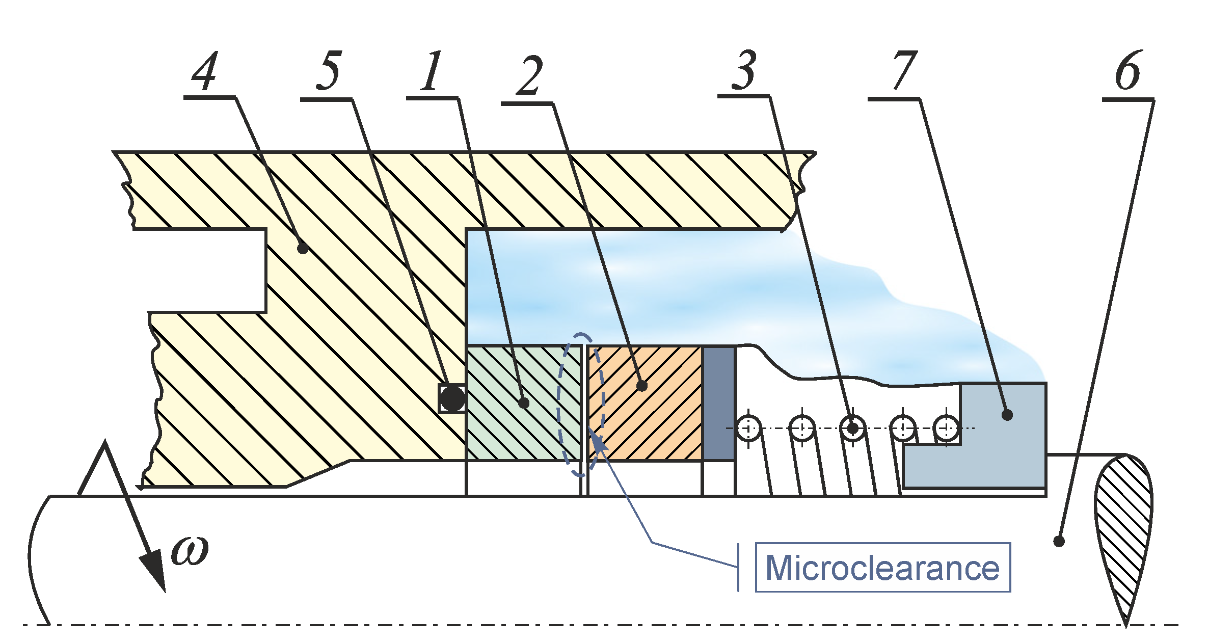
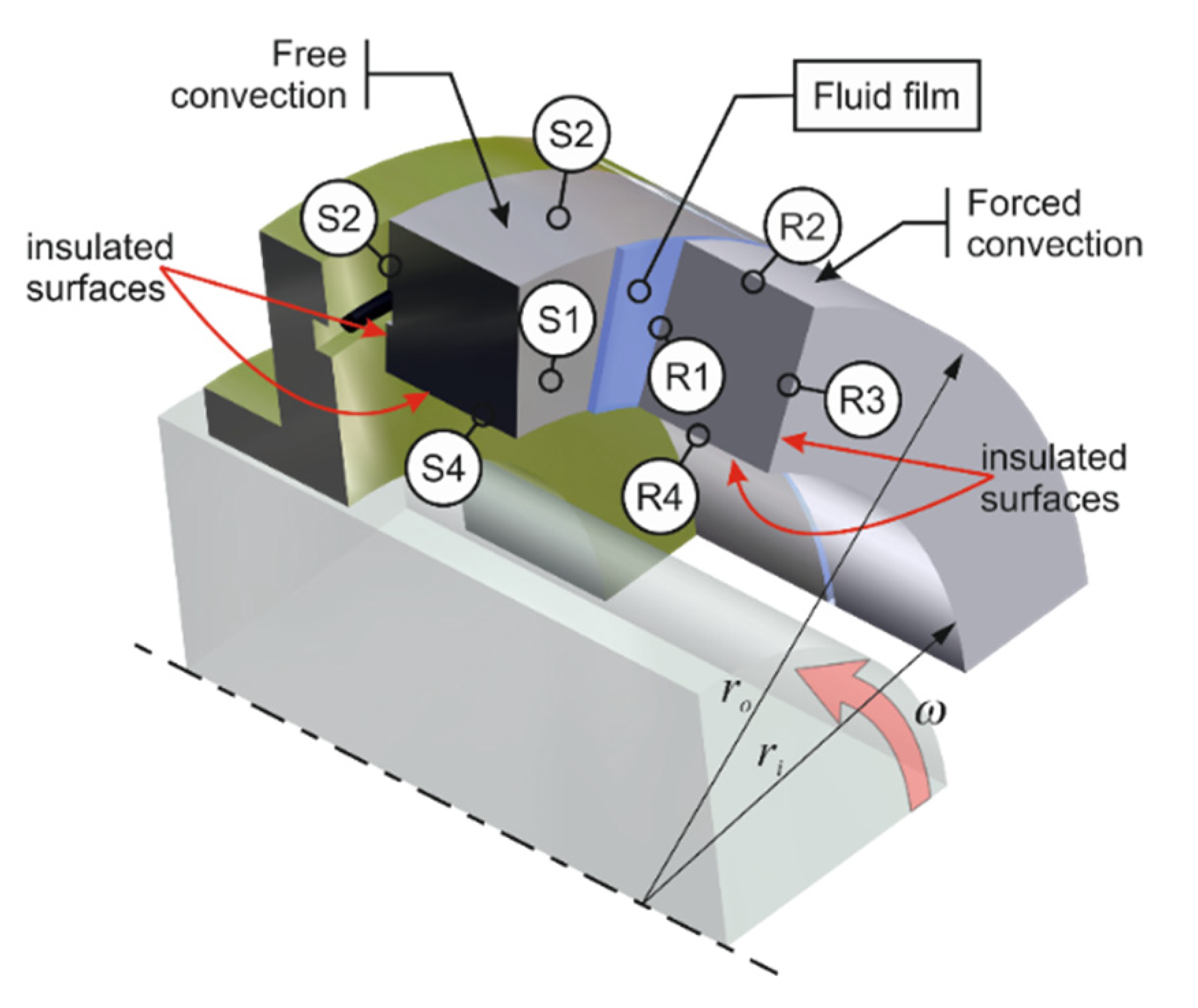
16]. The boundary conditions for the system considered are shown in Figure 2.
It is assumed that the surfaces S 3 and S 4 of the stator mounted to the housing and the surfaces R 3 and R 4 of the rotating ring are completely separated so there is no transfer of heat to the fluid surrounding the rings. This condition for both the stator and rotor can be written in the general form as:
θ n = 0 .
Another assumption is that the heat transfer across the surfaces S 1 and R 1 (faces) of the stator and rotor, respectively, which are in direct contact with the fluid filling the radial clearance, occurs by conduction. This implies that the value of the heat flux at the surface of the ring is equal to that of the fluid in the clearance:
λ s θ s z = λ f θ f z = q s v ( r )   with   θ s = θ f   for   S 1
and
q r v ( r ) = λ f θ f z = λ r θ r z   with   θ f = θ r   for   R 1
It is also assumed that the heat transfer across the outer surfaces of the rings S 2 and R 2 (Figure 2), being in contact with the process fluid, takes place by convection. For the stator and rotor, the condition can be written in the general form:
λ θ r | r = r o = α θ | r = r o
In the analytical calculations, an additional assumption is made that the heat transfer coefficients for the stator the rotor have different values. This is due to the fact the transfer of heat to the process fluid is higher from the rotating ring than from the stationary ring, with the latter occurring by free convection.
It is assumed that the heat transfer coefficient for the stationary ring has a constant value; the value is given in Table 1.
For the rotor, the heat transfer coefficient is calculated using relationships [11]:
α r = 0.133 Re D 2 / 3 Pr 1 / 3 λ f D
where D is the outer diameter of the seal and R e D is the Reynolds number based on this diameter; the parameters λ f and P r are the thermal conductivity and the Prandtl number of the fluid, respectively.
The Reynolds and Prandtl numbers are described as [17]:
Re D = ω D 2 ρ μ
and
Pr = C p μ λ f
The next section describes the analytical solution of the mathematical model of the heat transfer in non-contacting face seals.

3.1. Analytical Solution of the Heat Transfer Model

The formulated mathematical model is solved analytically using the technique of separation of variables, like in [18,19]. The first step of the problem-solving process consists of determining the distributions of temperature within the sealing rings by defining the general form of the functions satisfying the differential Equation (8) for both the stator and the rotor. Subsequently, a general solution is found to satisfy the specific boundary conditions defined by relationships (20)–(23). The equations describing the distributions of temperature are as follows:
  • for the stator:
    T s = T 0 + n = 1 B n s cosh ( s n s z s ) ( J 0 ( s n s r ) J 1 ( s n s r i ) Y 1 ( s n s r i ) Y 0 ( s n s r ) )
  • for the fluid film separating the rings:
    T f = T 0 + 1 2 μ λ f ω 2 r 2 h 2 ( h 2 ( z f ) 2 ) + + n = 1 B n r cosh ( s n r z r ) ( J 0 ( s n r r ) J 1 ( s n r r i ) Y 1 ( s n r r i ) Y 0 ( s n r r ) )
  • and for the rotor:
    T r = T 0 + n = 1 B n r cosh ( s n r z r ) ( J 0 ( s n r r ) J 1 ( s n r r i ) Y 1 ( s n r r i ) Y 0 ( s n r r ) )
The above relationships describing the distributions of temperature within the stator–rotor system and the fluid film will be used to determine the stress fields.

3.2. Analytical Solution of the Thermoelasticity Model

The model describing thermoelastic phenomena is relatively complex and its analytical solution requires performing complex calculations. A general method of the model solution will be used for both rings. The first stage involves determining the thermoelastic displacement potential function using Equation (27) or Equation (29), with the superscripts for the stator and rotor being omitted:
θ ( r , z ) = n = 1 B n cosh ( s n z ) ( J 0 ( s n r ) J 1 ( s n r i ) Y 1 ( s n r i ) Y 0 ( s n r ) )
The thermoelastic displacement potential function is written as:
Φ = K 2 n = 1 B n s n ( z L ) sinh ( s n z ) ( J 0 ( s n r ) J 1 ( s n r i ) Y 1 ( s n r i ) Y 0 ( s n r ) )
As assumed, the above equation needs to satisfy Relationship (13).
The second step requires finding the Michell function. It is predicted to have the following form:
M = K 2 n = 1 B n s n 3 ( J 0 ( s n r ) J 1 ( s n r i ) Y 1 ( s n r i ) Y 0 ( s n r ) ) ( ( 1 2 ν ) sinh ( s n z ) + + ( z L ) s n cosh ( s n z ) )
Substituting these relationships into Equation (18) yields the components of the stress tensor:
σ r r = 4 K G n = 1 ( B n cosh ( s n z ) ( Y 1 ( s n r i ) J 1 ( s n r ) + Y 1 ( s n r i ) J 1 ( s n r ) ν + J 1 ( s n r i ) Y 1 ( s n r ) J 1 ( s n r i ) Y 1 ( s n r ) ν ) Y 1 ( s n r i ) s n r )
σ ϕ ϕ = 4 G K n = 1 ( B n cosh ( s n z ) Y 1 ( s n r i ) s n r ( s n r Y 1 ( s n r i ) J 0 ( s n r ) + s n r J 1 ( s n r i ) Y 0 ( s n r ) + + ν s n r J 0 ( s n r ) Y 1 ( s n r i ) + ν s n r J 1 ( s n r i ) Y 0 ( s n r ) + + Y 1 ( s n r i ) J 1 ( s n r ) ν Y 1 ( s n r i ) J 1 ( s n r ) + J 1 ( s n r i ) Y 1 ( s n r ) + ν J 1 ( s n r i ) Y 1 ( s n r ) ) )
The relationships describing displacements are given as:
u r = 2 K n = 1 B n ( 1 + ν ) ( Y 1 ( s n r i ) J 1 ( s n r ) + J 1 ( s n r i ) Y 1 ( s n r ) ) cosh ( s n z ) Y 1 ( s n r i ) s n
u z = 2 K n = 1 B n ( 1 + ν ) ( J 0 ( s n r ) Y 1 ( s n r i ) + J 1 ( s n r i ) Y 0 ( s n r ) ) sinh ( s n z ) Y 1 ( s n r i ) s n
The above relationships were used to graphically represent fields of stresses and displacements occurring in the sealing rings due to uneven distributions of temperature.

4. Results and Discussion

A numerical analysis was conducted to verify the relevant hypotheses and assess the influence of the selected parameters on the behavior of non-contacting face seals. In the reference case, water is used as the fluid. Water as a working medium is commonly used in various types of utility installations. The sealing rings are assumed to be in alignment and their faces create a radial clearance with a constant height h o . Another assumption is that the process fluid is not in contact with the outer surfaces of the rings, except for the cylindrical surfaces, where the heat transfer to the fluid occurs by convection (Figure 2). The geometrical and performance parameters of the seal under consideration are defined in Table 1.
One of the first problems mechanical designers need to deal with is selecting the right seal, i.e., a seal that meets the criteria specified for the sealing fluid to be used in the turbomachine, including its temperature and pressure. They must also predict the dry running condition, which takes place during the machine startup and shutdown. Another important problem design engineers have to consider is the chemical durability of the sealing rings and secondary seals. The materials they select for these elements need to have appropriate physicochemical properties. The most common materials used for mechanical seals are characterized in Table 2.
The materials used for the sealing rings need to be suitable for the seal operating conditions.
In the case of non-contacting face seals, the sealing rings are usually made of dissimilar materials, i.e., ones differing in physicochemical properties. This, however, leads to the occurrence of a sequence of undesirable phenomena, starting with uneven heat transfer from the radial clearance to the surrounding fluid, followed by asymmetric thermoelastic deformations of the rings, then a change in the geometry of the radial clearance and, finally, an increase in the leakage rate.
Non-contacting face seals, also called mechanical face seals, are used in many mechanical sealing systems. The correct performance of non-contacting seals is conditioned by the properly selected parameters of the sealing rings. One of the most significant parameters that have a direct effect on the distribution of pressure within the fluid film and the heat flux generated in the clearance is the angular velocity of the rotor.
The key feature of mechanical seals is the ability to operate in ‘no lubrication’ conditions. In practice, this does not last long, but the materials used for the sealing rings must have sufficient hardness and thermal resistance to withstand an increase in temperature caused by excessive friction forces. Two types of material configurations are used for the sealing rings: ‘hard-hard’ and ‘hard–soft’.
Seals with both rings made of hard materials, e.g., silicon carbide-silicon carbide or tungsten carbide–tungsten carbide, exhibit high resistance to many active chemical compounds, but they are characterized by little resistance to dry running. Seals with a hard-soft ring configuration, on the other hand, e.g., carbon–tungsten carbide, are more resistant to dry running but have limited chemical resistance to fluids other than water. As the selection of ring materials to match the seal operating conditions is an open problem, a numerical analysis is necessary. This study was conducted for two types of rotor materials, i.e., silicon carbide and tungsten carbide, and three types of stator materials, i.e., silicon carbide, tungsten carbide, and alumina (ceramic). The numerical analysis was thus performed for six pairs of sealing rings.
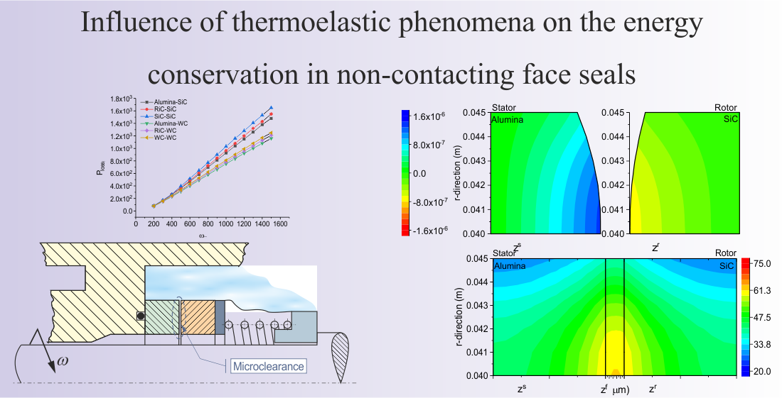
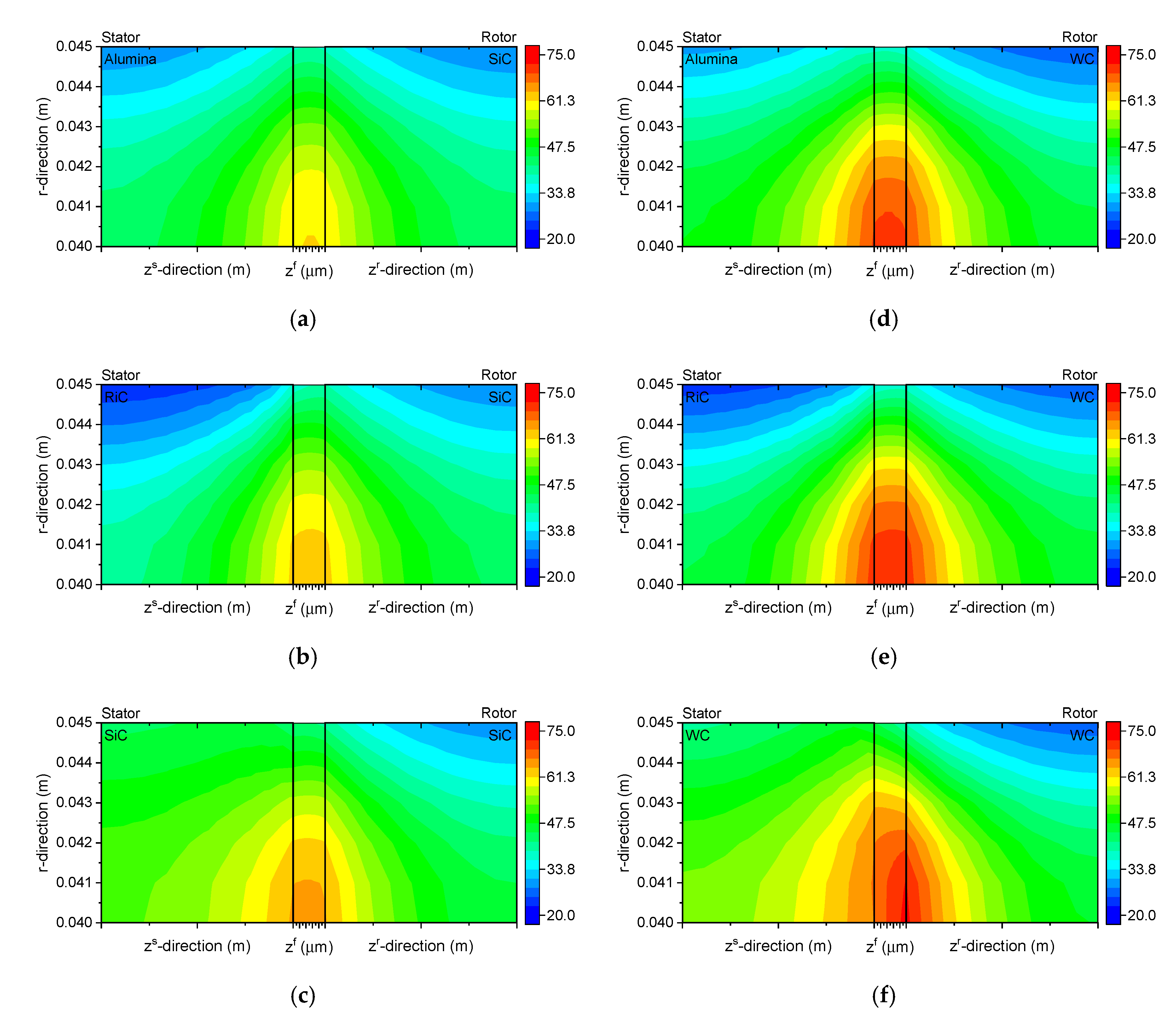
The diagrams in Figure 3 illustrate temperature distributions in the cross-sections of the sealing rings and the fluid film separating them. The results show that in all the cases considered, the maximum temperature of the fluid film is registered along the inner radius r i . Depending on the kind of used materials and theirs combinations, the temperature range is 61.4–71.6 °C for the inner radius r i = 0.04   ( m ) of the fluid film.
According to Figure 3, the temperature of the water is close to the saturation temperature of the water under the condition of atmospheric pressure. For this reason, the temperature of the water is limited and should be below the boiling temperature. The evaporation of the working medium can lead to loss of the lubricating film stability and consequently to working with dry friction conditions between the sliding rings.
The lowest temperature of the fluid film is reported for the Alumina-SiC pair (Figure 3a), while the highest for the RiC-WC and WC-WC pairs (Figure 3e,f). Another observation is a large difference in temperature along the outer radius r o . It should be noted that the analyzed model assumes forced convection for the rotor, which implies increased heat transfer to the fluid surrounding this ring. From Figure 3b,e, it is evident that, for the RiC-SiC and RiC-WC pairs, the temperature along the outer radius is up to 5 °C lower for the stator than for the rotor. When the stator and rotor are made of the same material, i.e., for the SiC-SiC and WC-WC pairs (Figure 3c,f), the situation is the opposite; the temperature of the stator along the outer radius is 15 °C higher than that of the rotor. Another important observation is that the use of silicon carbide in a combination of material types lowers the temperature of the working fluid, in all cases. This is due to the increased thermal conductivity of silicon carbide.
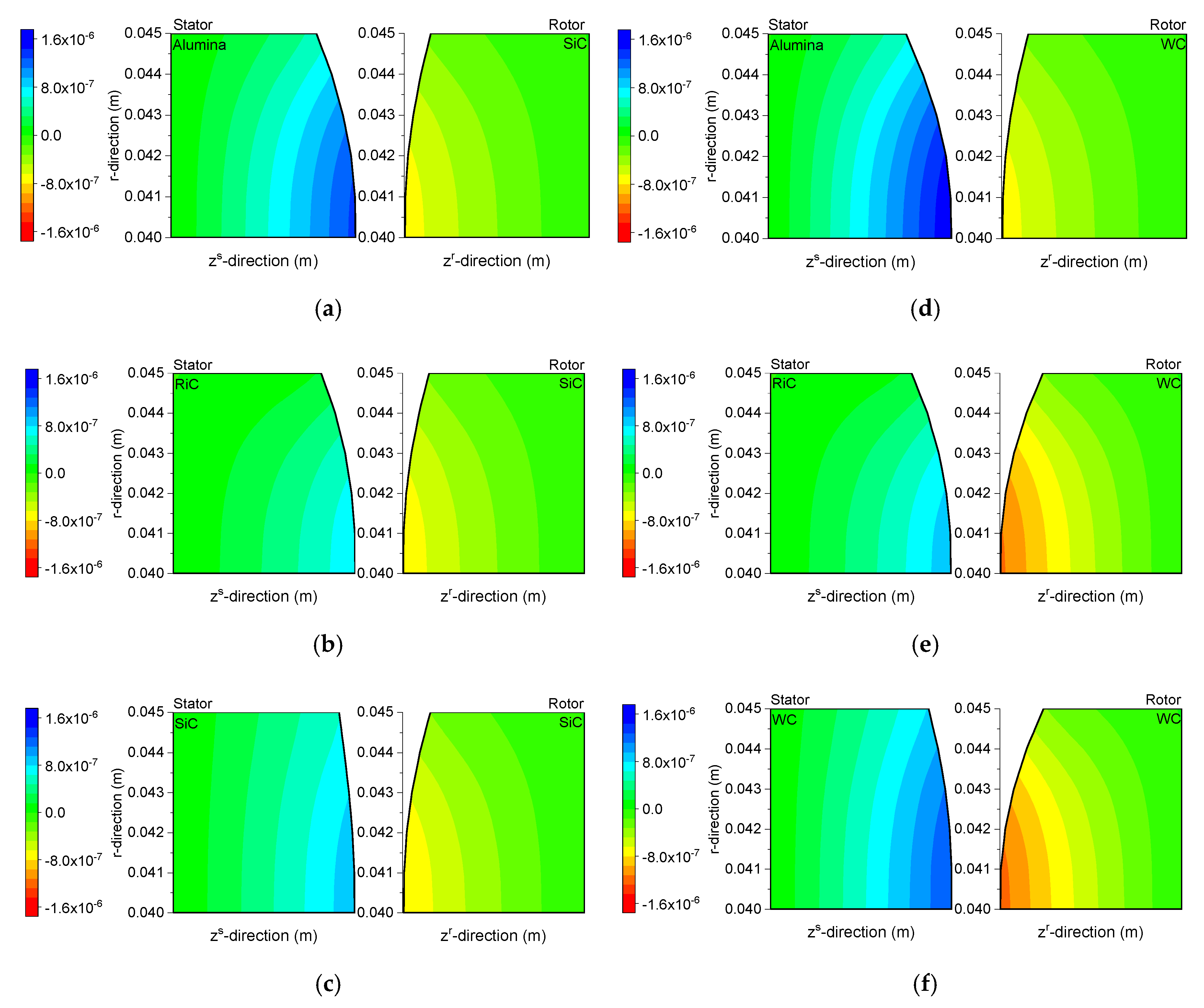
The temperature differences in the ring cross-sections are reduced to a minimum to ensure minimum thermal stresses.
Figure 4 shows the fields of angular displacements in the sealing rings. Since the displacements were very small, of the order of 10 6 ( m ) , the deformations of the rings caused by thermal stresses were magnified 2000-fold. Thanks to that, it is possible to observe warps on the sealing rings. The numerical data indicate that the highest displacements of the order of 1.2 × 10 6 ( m ) occurrence along the inner radii of the rings in a seal where both the stator and the rotor are made of tungsten carbide (Figure 4f).
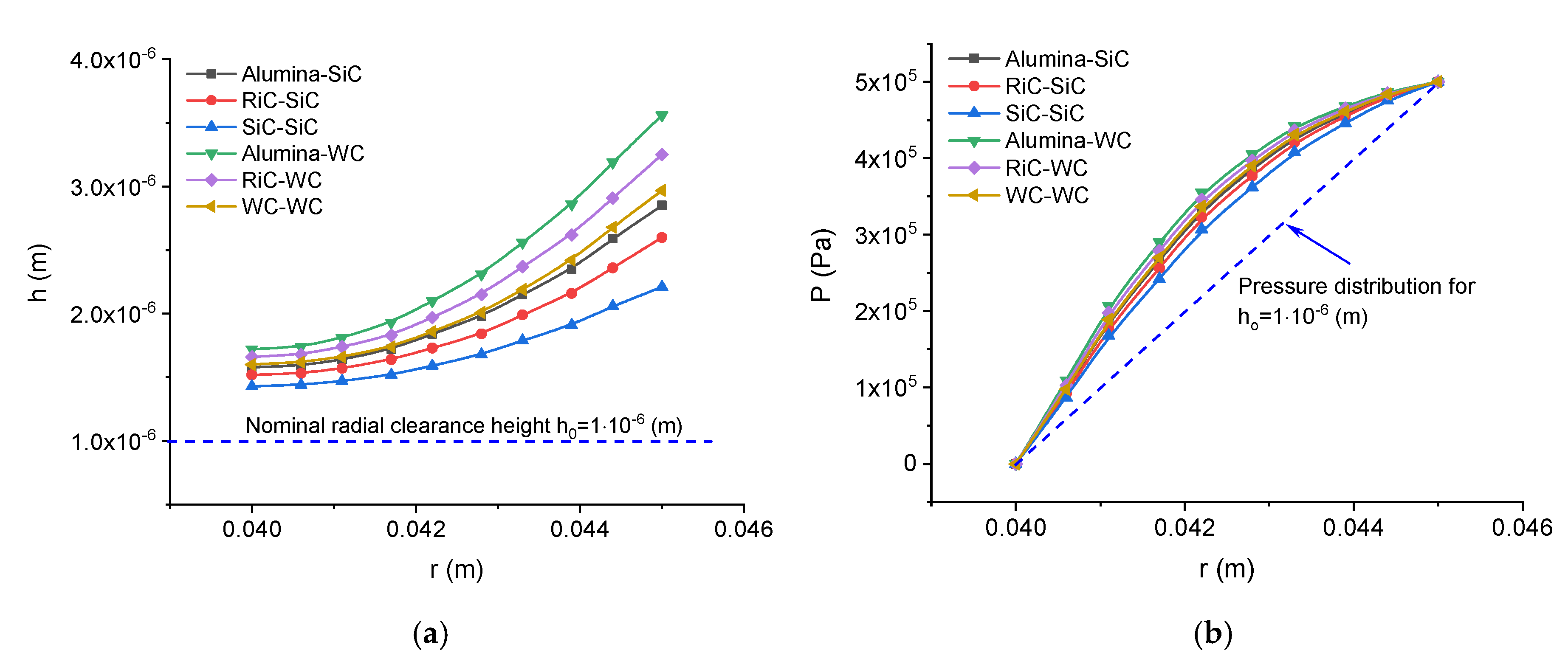
A change in the geometry of the sealing rings causes a change in the height of the radial clearance, taken into consideration in Relationships (1), and a change in the distribution of pressure, calculated using the Reynolds equation.
Figure 5 provides a graphical representation of a change in the function of the radial clearance height, taking account of the thermal deformations of the sealing rings resulting from the asymmetric distribution of temperature in these elements. For each case considered, there is an increase in the minimum height of the radial clearance; the highest value of 1.72 × 10 6 ( m ) is reported for the Alumina–WC pair, whereas the lowest of 1.43 × 10 6 ( m ) is observed for the SiC-SiC pair. A change in the geometry of the radial clearance has a direct effect on the distribution of pressure in the fluid film (Figure 5b), which causes an increase in the opening force.
.
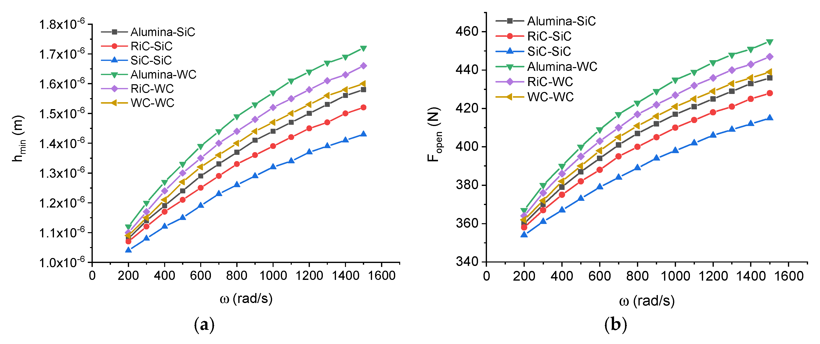
Figure 6 shows changes in the minimum height of the radial clearance and the opening force against the angular velocity of the machine shaft. An increase in this parameter causes an increase in the heat flux generated in the fluid film, according to Relationship (4). As a consequence, there is a rise in the temperature of the sealing rings-fluid film system, which is responsible for thermal deformations of the sealing rings, then a change in the geometry of the radial clearance and, finally, an increase in the fluid film pressure. All this leads to a greater radial force generated in the fluid film and a greater minimum distance between the sealing rings, as shown in Figure 6.
Power loss results mainly from the viscous shearing of the fluid film between the mating surfaces; it can be calculated from the following relationship [20]:
P l o s s = 0 2 π r i r o μ ω 2 r 2 h r d r d θ
The key parameter of the performance of non-contacting face seals is the fluid leakage rate, which is largely attributable to a change in the geometry of the radial clearance and it is described with the following formula:
Q v = ( r 0 2 π h 3 12 μ p r d θ ) | r = r i
As shown in Figure 7, the geometry of the clearance changes with changing temperature. 
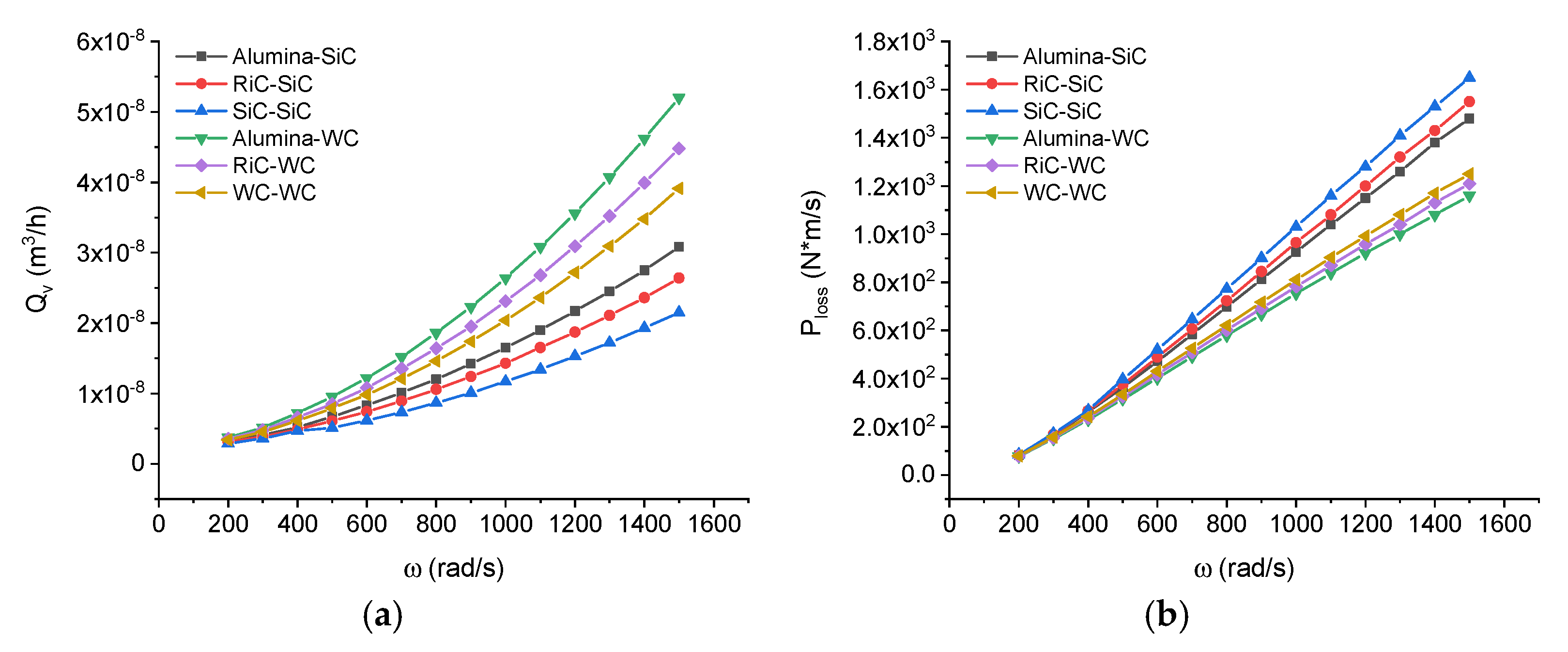
Figure 7 shows the curves of the volumetric flow rate and power loss against the angular velocity of the shaft.
From the curves in Figure 7, it is apparent that, when the angular velocity is low, i.e., ω = 300 (rad/s), the leakage rate and the power loss are very small for all the material pairs considered. An increase in the angular velocity causes an almost linear increase in the power loss in the stator-rotor system and an increase in the leakage rate. At ω = 1500 (rad/s), the maximum leakage rate is: Q v = 2 . 15 × 10 - 8 (rad/s), for the SiC-SiC pair and Q v = 5 . 2 × 10 - 8 (rad/s), for the Alumina-WC pair. At that angular velocity, i.e., ω = 1500 (rad/s), there may be a double difference in the leakage rate between some pairs of materials.
In the case of power loss, the situation is the opposite. An increase in the height of the radial clearance leads to a decrease in power loss, as illustrated in Figure 6a and Figure 7b.
The results suggest that omitting thermal deformations is too great a simplification of the model of non-contacting seals.
It should be noted that the values and character of thermal deformations are in agreement with the numerical results presented, for example, in [7].

5. Multi-Criteria Analysis

The multi-criteria analysis is a method used to facilitate the decision-making process when many variants are analyzed to select the best. In this case, the most appropriate pair of materials for the sealing rings is chosen. It is important to note that the criteria used in this analysis were selected and given weights subjectively by the author. The purpose of this multi-criteria analysis was to choose the best material pair variant to achieve the optimum seal performance, ring geometry and system temperature. Table 3 summarizes the criteria selected for the analysis.
The criteria used in the multi-criteria analysis can be expressed by means of measurable or unmeasurable parameters. All the criteria are given dimensionless numerical values to assess and compare the selected variants. The process of replacing dimensional values with dimensionless values is called normalization. Normalization may involve maximizing the variables (stimulants ( + ) ) or minimizing them (destimulants ( ) ). Signs ( + ) and ( ) are given in Table 3 next to the values of the weights.
The variants are rated on the basis of the synthetic estimates S i , which are calculated using the summation index, taking into consideration the weights of the particular criteria determined according to the formula:
S i = j = 1 m x i j ω j
The final estimate of the analyzed variants is calculated by reducing the sum of S i to a unity according to the following formula:
S i = S i / i = 1 n S i
The most favorable variant is that with the highest S i .
Table 4 explains the method for criteria normalization with the notations being as follows: x i j —normalized value of the i-th variant satisfying the j-th criterion; and x i j —value of the i-th variant satisfying the j-th criterion.
The calculation results obtained using the Van Delft and Nijkamp normalization method indicate that, for the predetermined heat transfer conditions and seal performance parameters, the volumetric flow rate is the lowest when both rings made of silicon carbide (Figure 8).
The multi-criteria analysis is suitable for facilitating the decision-making process in situations when there are many variants to consider and/or the results do not give a clear best choice.

6. Conclusions

Sealing systems, which are crucial elements of many industrial machines, need to be designed in such a way that they conform to stringent safety standards if hazardous substances are used as process fluids.
Non-contacting face seals have numerous applications mainly because they meet divergent demands concerning both efficient performance and environmental safety. The major requirement to be met by seals is to maintain leak-tightness, irrespective of changes in the internal factors. Meeting this condition; however, is extremely difficult and one of the reasons for this may be changes in the geometry of the radial clearance caused by thermal deformations. Such deformations are likely to result in a disturbance to the equilibrium of forces, i.e., an increase in the opening force, which contributes to a higher leakage rate.
There is a direct relationship between the radial clearance geometry, the equilibrium of forces acting on the sealing rings, the leakage rate and the power loss. A change in any of these parameters may result in the disturbances to the performance of the whole sealing system, and consequently a failure of the machine in which the seal is installed. One of the main influencing the operation of mating slide rings in non-contact face seals is power loss (Figure 7b). Choosing the appropriate materials for the mating rings can provide a balance between reducing power loss and leakage. The decrease of power losses has a significant impact on the reduction of production costs etc.
The main aim of the research was realized. Based on simulation tests, the influence of material selection on working rings on power loss and leakage rate was confirmed.
The effectiveness of a seal depends on some factors. First of all, it is essential to select the right type of seal for a given application. Then, at the design stage, it is necessary to specify the desired temperature of the fluid film and the rings. It is also vital to predict the thermal deformations of the rings in order to prevent excessive wear of their surfaces as well as uncontrolled fluid leakage or power loss.

Funding

This research received no external funding.

Conflicts of Interest

The authors declare no conflict of interest.

Nomenclature

bscale factor (1/°C); for water b = 0.0175,
Cpspecific heat,
edilatation e = ε k k ,
EYoung’s modulus
Gelastic constant, G = ϑ ,
hclearance height along the radial coordinate r,
honominal clearance height,
Ls,Lrthickness of the stator and rotor, respectively,
nnormal vector to the surface,
pfluid pressure,
pi,pofluid pressure at the inner and outer radii, respectively,
PrPrandtl number,
ReDReynolds number,
ri,roinner and outer radii, respectively,
snconstant ( 1 m ),
Tabsolute temperature at a specific point of the body,
Tffluid temperature along the r and z coordinates,
Tmaverage temperature of the fluid film,
Totemperature of the process fluid (generally assumed to be constant),
ur,uzring displacements along the r and z coordinates, respectively.
α s free convection heat transfer coefficient,
λ , ϑ Lame constants, where λ = ν E ( 1 + ν ) ( 1 2 ν ) and ϑ = E 2 ( 1 + ν )
λ f heat conduction coefficient for fluid,
λ s , λ r heat conduction coefficient for the stator and rotor, respectively,
μ o fluid dynamic viscosity at To
ν ϕ distribution of fluid velocity in the clearance,
θ = T T o change in the fluid temperature,
θ s , θ r changes in the stator and rotor temperatures along the r and z coordinates, respectively
ρ fluid density,
σ r r , σ ϕ ϕ stresses in the r and ϕ directions, respectively,
ω angular velocity.

References

  1. Pascovici, M.D.; Etsion, I. A thermohydrodynamic analysis of a mechanical face seal. J. Tribol. 1992, 114, 639–645. [Google Scholar] [CrossRef]
  2. Tournerie, B.; Danos, J.C.; Frêne, J. Three-Dimensional Modeling of THD Lubrication in Face Seals. J. Tribol. 2001, 123, 196. [Google Scholar] [CrossRef]
  3. Brunetière, N.; Tournerie, B.; Frene, J. TEHD Lubrication of Mechanical Face Seals in Stable Tracking Mode: Part 2—Parametric Study. J. Tribol. 2003, 125, 617. [Google Scholar] [CrossRef]
  4. Brunetière, N.; Tournerie, B.; Frene, J. TEHD Lubrication of Mechanical Face Seals in Stable Tracking Mode: Part 1—Numerical Model and Experiments. J. Tribol. 2003, 125, 608. [Google Scholar] [CrossRef]
  5. Blasiak, S.; Kundera, C. A Numerical Analysis of the Grooved Surface Effects on the Thermal Behavior of a Non-Contacting Face Seal. Procedia Eng. 2012, 39, 315–326. [Google Scholar] [CrossRef] [Green Version]
  6. Blasiak, S.; Kundera, C.; Bochnia, J. A Numerical Analysis of the Temperature Distributions in Face Sealing Rings. Procedia Eng. 2012, 39, 366–378. [Google Scholar] [CrossRef] [Green Version]
  7. Li, C.-H. Thermal Deformation in a Mechanical Face Seal. Am. Soc. Lubr. Eng. Trans. 1976, 19, 146–152. [Google Scholar] [CrossRef]
  8. Banerjee, B.N. The influence of thermoelastic deformations on the operation of face seals. Wear 1980, 59, 89–110. [Google Scholar] [CrossRef]
  9. Emery, A.F. Thermal Stress Fracture in Elastic-Brittle Materials. In Thermal Stresses in Severe Environments; Hasselman, D.P.H., Heller, R.A., Eds.; Springer: Boston, MA, USA, 1980; pp. 95–121. ISBN 978-1-4613-3158-2. [Google Scholar]
  10. Etsion, I.; Pascovici, M.D. A Thermohydrodynamic Analysis of a Misaligned Mechanical Face Seal. Tribol. Trans. 1993, 36, 589–596. [Google Scholar] [CrossRef]
  11. Gu, B.; Zhou, J.; Chen, Y.; Sun, J. Frictional heat transfer regularity of the fluid film in mechanical seals. Sci. China Technol. Sci. 2008, 51, 611–623. [Google Scholar] [CrossRef]
  12. Blasiak, S. Time-fractional heat transfer equations in modeling of the non-contacting face seals. Int. J. Heat Mass Transf. 2016, 100, 79–88. [Google Scholar] [CrossRef]
  13. Blasiak, S. Heat transfer model for the wavy-tilt-dam mechanical seals using Green’s Function Method. In Engineering Mechanics; Fuis, V., Ed.; Brno University of Technology: Brno, Czech Republic, 2017; pp. 158–161. ISBN 978-80-214-5497-2. [Google Scholar]
  14. Zhou, J.F.; Gu, B.; Chen, Y. An Improved Design of Spiral Groove Mechanical Seal. Chin. J. Chem. Eng. 2007, 15, 499–506. [Google Scholar] [CrossRef]
  15. Noda, N.; Hetnarski, R.B.; Tanigawa, Y. Thermal Stresses, 2nd ed.; Taylor & Francis Group: Abingdon, UK, 2003; ISBN 9781560329718. [Google Scholar]
  16. Strąk, K.; Piasecka, M.; Maciejewska, B. Spatial orientation as a factor in flow boiling heat transfer of cooling liquids in enhanced surface minichannels. Int. J. Heat Mass Transf. 2018, 117, 375–387. [Google Scholar] [CrossRef]
  17. Du, Q.; Gao, K.; Zhang, D.; Xie, Y. Effects of grooved ring rotation and working fluid on the performance of dry gas seal. Int. J. Heat Mass Transf. 2018, 126, 1323–1332. [Google Scholar] [CrossRef]
  18. Kukla, S.; Siedlecka, U. Fractional heat conduction in a sphere under mathematical and physical Robin conditions. J. Theor. Appl. Mech. 2018, 56, 339. [Google Scholar] [CrossRef]
  19. Maciejewska, B.; Piasecka, M. An application of the non-continuous Trefftz method to the determination of heat transfer coefficient for flow boiling in a minichannel. Heat Mass Transf. 2017, 53, 1211–1224. [Google Scholar] [CrossRef] [Green Version]
  20. Ruan, B. Numerical Modeling of Dynamic Sealing Behaviors of Spiral Groove Gas Face Seals. J. Tribol. 2002, 124, 186. [Google Scholar] [CrossRef]
Figure 1. Non-contacting face seal: 1—stator, 2—rotor, 3—spring, 4—housing, 5—O-ring, 6—shaft, 7—steady pin.
Energies 13 05283 g001
Figure 2. Heat transfer conditions for the FMR-type non-contacting face seal, where S 1 , S 2 , S 3 , S 4 —surfaces of the stator; and R 1 , R 2 , R 3 , R 4 —surfaces of the rotor.
Energies 13 05283 g002
Figure 3. Temperature distributions in the cross-sections of the sealing rings and the fluid film at ω = 1500   ( rad / s ) , (a) Alumina-SiC; (b) RiC-SiC; (c) SiC-SiC; (d) Alumina-WC; (e) RiC-WC; (f) WC-WC pairs of matrices.
Energies 13 05283 g003
Figure 4. Distributions of axial displacements in the cross-sections of the sealing rings at ω = 1500   ( rad / s ) , (a) Alumina-SiC; (b) RiC-SiC; (c) SiC-SiC; (d) Alumina-WC; (e) RiC-WC; (f) WC-WC pairs of matrices.
Energies 13 05283 g004
Figure 5. Clearance height and the fluid pressure distribution versus the ring radius at ω = 1500   ( rad / s ) , (a) Clearance height; (b) fluid pressure distribution, versus the ring radius at ω = 1500   ( rad / s )
Energies 13 05283 g005
Figure 6. Minimum radial clearance height and opening force, against the angular velocity of the shaft, (a) Minimum radial clearance height; (b) opening force, against the angular velocity of the shaft.
Energies 13 05283 g006
Figure 7. Volumetric flow rate and power loss, versus the angular velocity of the shaft, (a) Volumetric flow rate; (b) power loss, versus the angular velocity of the shaft.
Energies 13 05283 g007
Figure 8. Results of the multi-criteria analysis.
Energies 13 05283 g008
Table 1. Geometrical and performance parameters.
GeometryPerformance Parameters
Inner radius ri0.040 (m)Angular velocity ω200–1500 (rad/s)
Outer radius ro0.045 (m)Nominal seal clearance ho1 × 10−6 (m)
Ring thickness Ls and Lr0.005 (m)Fluid temperature To20 (°C)
Thermal conductivity λf0.65 (W/m K)Heat transfer coefficient αs18,000 (W/m2 K)
Table 2. Properties of materials used for the sealing rings.
MaterialYoung’s Modulus
E (GPa)
Poisson’s Coefficient
ν
Thermal Conductivity
λ (W m−1 K−1)
Linear Thermal Expansion Coefficient
τ (10−6 °C)
SiC (Silicon Carbide)4000.171504.3
Resin-impregnated carbon240.12104.9
Alumina (Ceramic)3500.23307.5
Tungsten carbide (WC)6300.24855.4
Table 3. Criteria for Analysis.
CriteriaUnitWeight
ω
Materials
Alumina-SiCRiC-SiCSiC-SiCAlumina-WCRiC-WCWC-WC
Performance
Volumetric
flow rate
m3/h0.25 ( ) 3.08 × 10−82.64 × 10−82.15 × 10−85.20 × 10−84.48 × 10−83.91 × 10−8
Power lossNm/s0.15 ( ) 148015501650116012101250
Opening forceN0.2 ( + ) 436428415455447439
Geometry
Minimum radial clearancem0.2 ( ) 1.58 × 10−61.52 × 10−61.43 × 10−61.72 × 10−61.66 × 10−61.6 × 10−6
Temperature
Difference in fluid temperature°C0.2 ( ) 22.223.922.532.333.728.5
Table 4. Method for the criteria normalization.
Normalization MethodMaximization
(Stimulants)
Minimization
(Destimulants)
Van Delft and Nijkamp approach x i j = x i j i = 1 n x i j 2 x i j = 1 x i j i = 1 n x i j 2

