Review

Review of Time and Space Harmonics in Multi-Phase Induction Machine

1
Faculty of Electrical Engineering, University of West Bohemia, 306 14 Pilsen, Czech Republic
2
Faculty of Electrical Engineering and Informatics, Technical University of Kosice, 040 01 Košice, Slovakia
*
Author to whom correspondence should be addressed.
Energies 2020, 13(2), 496; https://doi.org/10.3390/en13020496
Submission received: 13 December 2019 / Revised: 9 January 2020 / Accepted: 15 January 2020 / Published: 19 January 2020
(This article belongs to the Special Issue Advances in Rotating Electric Machines)

Abstract

:
Modern multiphase electric machines take advantage of additional degrees of freedom for various purposes, including harmonic current injection to increase torque per ampere. This new approach introduces a non-sinusoidal air gap flux density distribution causing additional technical problems and so the conventional assumptions need to be revised. The paper presents a methodology for synthesis of air gap magnetic field generated by a symmetrically distributed multiphase windings including the rotor field reaction due to the machine’s load. The proposed method is suitable either for single-layer or double layer windings and can be adopted either for full-pitched or chorded winding including slots effects. The article analyses the air gap flux density harmonic content and formulates conclusions important to multiphase induction motors. It also discusses effects of time harmonic currents and illustrates the principle of changing number of pole-pairs typical for harmonic currents being injected to increase torque.

Graphical Abstract

1. Introduction

Over the past few years the modern industry has recorded a huge and intensive development in power electronics and drives and has brought many technical upgrades not only in public transportation. This rapid technological progress results in less industrial energy consumption and improves environmental issues. One of the most frequently discussed topics relating to the traffic environment [1,2,3] is replacing conventional combustion engine vehicles with fully electric (battery) vehicles (EVs). The initial concept of EV [4,5] comes from the previous experience with hybrid electric vehicles (HEVs), which later evolved into the popular plug-in hybrids (PHEVs). No matter what type of EV is considered, they are mostly powered by standard ac three-phase electric motors [6].
More than 80% of electric vehicles currently use rare earth permanent magnet synchronous motors (PMSM) allowing vehicle manufacturers to increase the efficiency [7,8] compared to traditional induction motors, especially at lower motor speeds. The improved efficiency brings either an increase in transport range or a reduction in battery size (and also the cost) for a given motor weight and vehicle specification. Compared to typical city-driving vehicles, powerful highway vehicles are designed to operate at higher speeds, which somewhat reduces the relative performance increase gained by rare earth magnets and reduces their advantage over induction machines [9]. Moreover, the rising cost and complicated political situation on the market with rare-earth magnets is another very important reason [10] why manufactures start choosing induction motors [11] as main drive units for their electrical vehicles. This tendency can be observed especially when talking about higher performance and luxury vehicles, such as e-buses, locomotives, or vehicles from Audi or Tesla.
The modern e-mobility trends increasingly focus on multiphase variable-speed motor drives [12] since they could provide the transportation with numerous traction and economic advantages [13]. Probably the first mention of a multiphase electric drive dates back to 1969, where the author of [14] proposed the concept of a five-phase inverter-fed induction motor lately extended to a six-phase double-star induction motor, referred in [15,16].
This early interest in multiphase machines was mainly initiated by the possibility of torque ripple reduction, higher reliability and higher fault tolerance. Another strong argument is that for a given motor power, the input power per phase is reduced, resulting in lower demands on the inverter power electronics components. Moreover, the winding I2R losses are inversely proportional to the square of winding distribution factor, hence the higher number of phases may significantly increase the overall motor efficiency.
Maximum theoretical value of winding loss reduction is determined in [17] as 8.8%. Moreover, as shown in [18,19,20,21,22], the multiphase motors may be powered with additional time harmonics injected into the winding to decrease the input current (rms value) while keeping the same torque, which is particularly relevant to the traction battery applications.
The main disadvantage lies in limited slots number available for given stator diameter, the greater number of phases, the lower the number of slots per pole per phase and consequently higher magnitudes of space harmonics. This may be even more problematic in case of outer-rotor machines with narrow-shaped slots.
No matter what number of phases is considered, electric motors are always accompanied by non-linearities and parasitic effects, usually connected with harmonics [23,24,25,26], that cause ripple of the input current and the torque, produce noise and increase losses.
These harmonics are often produced by dead times in pulse width modulation (PWM), supply voltage unbalance, magnetic circuit saturation, non-sinusoidal winding distribution, lamination slotting and some other non-linearities and asymmetries.
According to the nature of their origin, we can classify these harmonics as time harmonics and space harmonics [27], while their mutual interaction cannot be neglected [28]. This study describes/recapitulates occurrence and behavior of time/space harmonics in multiphase induction machines.

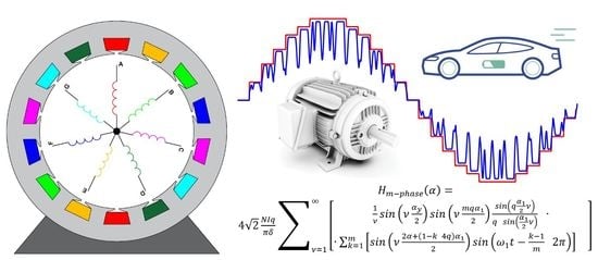
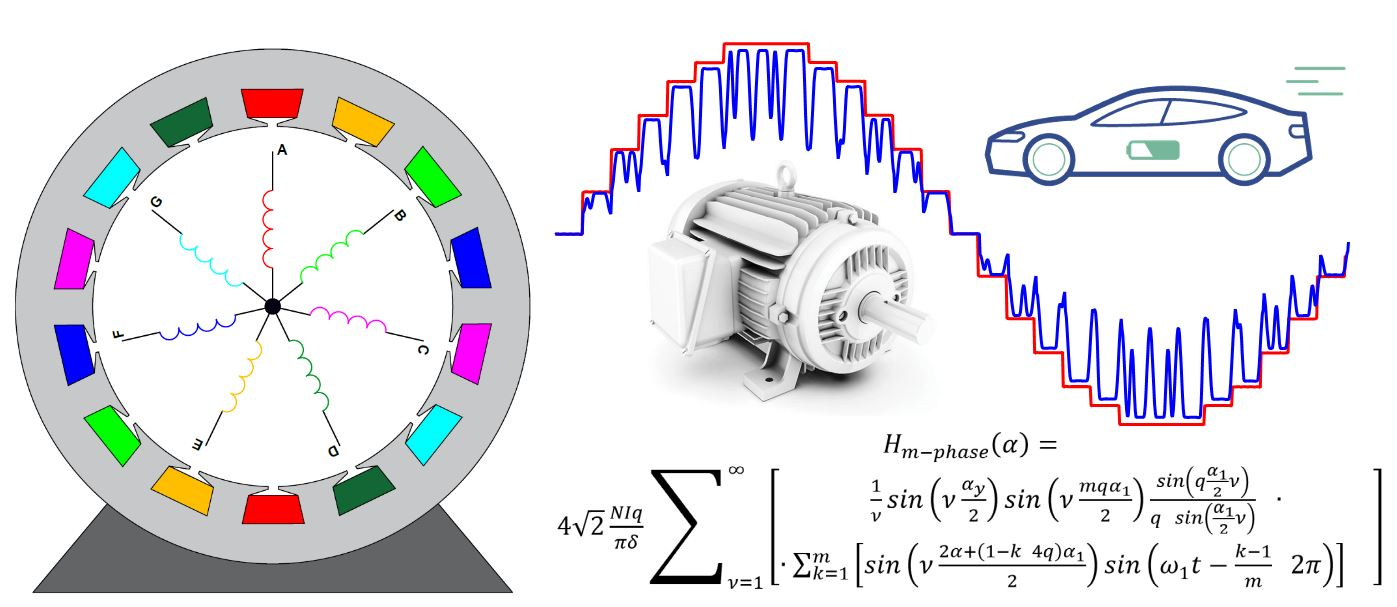
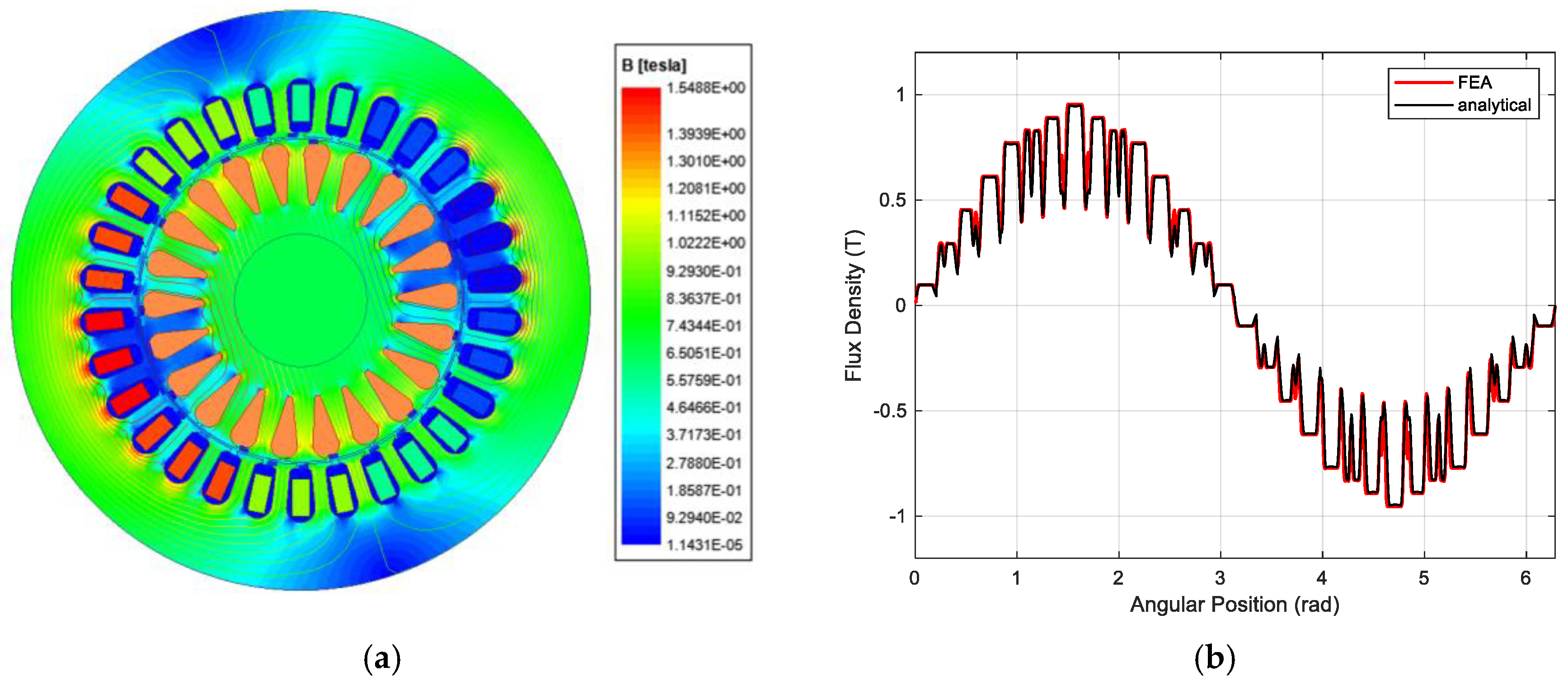
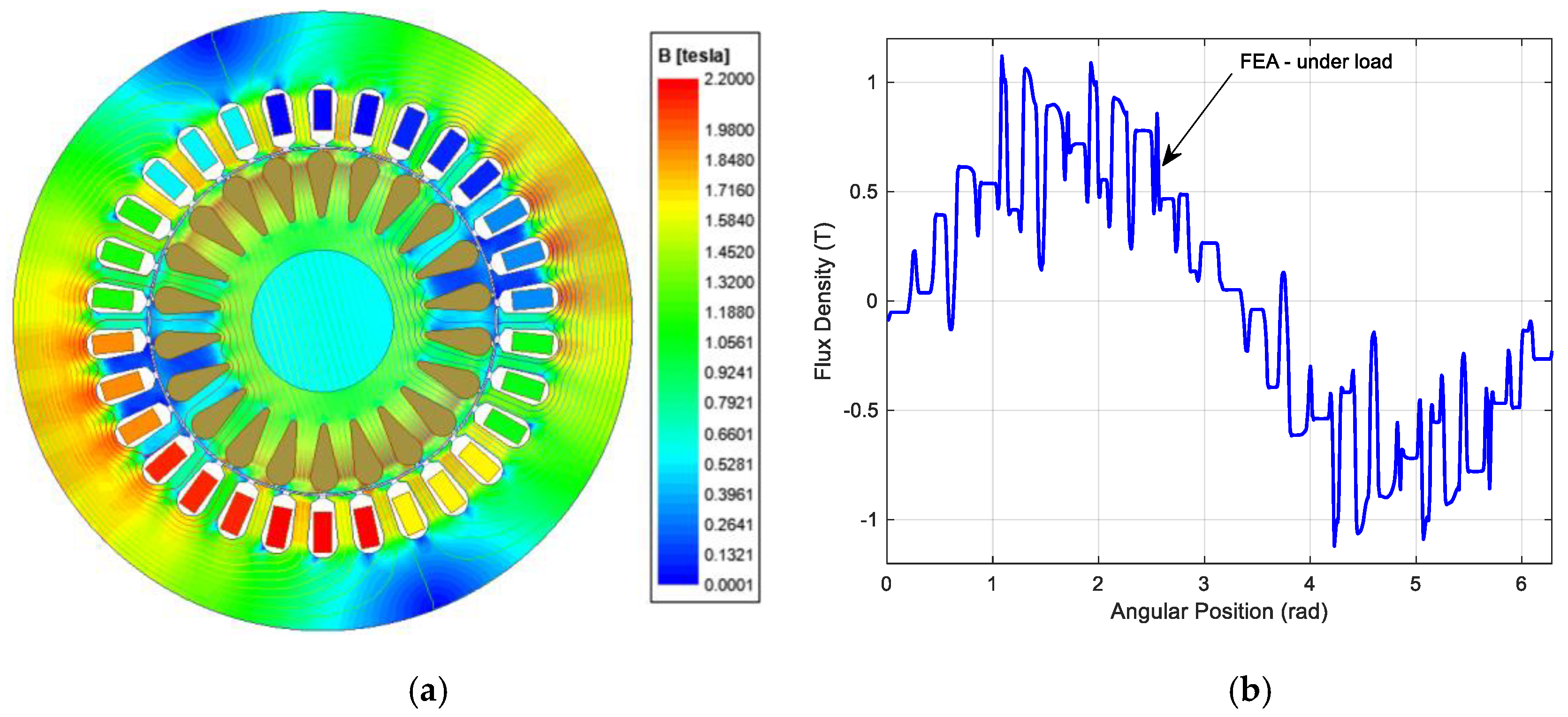
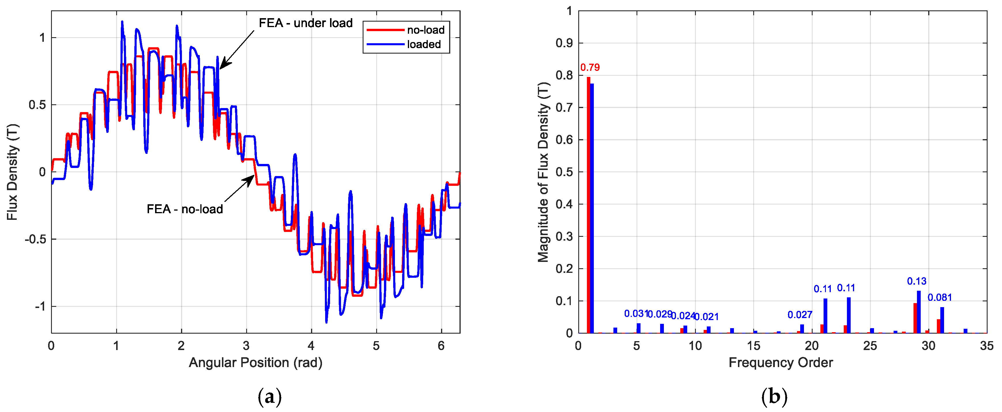
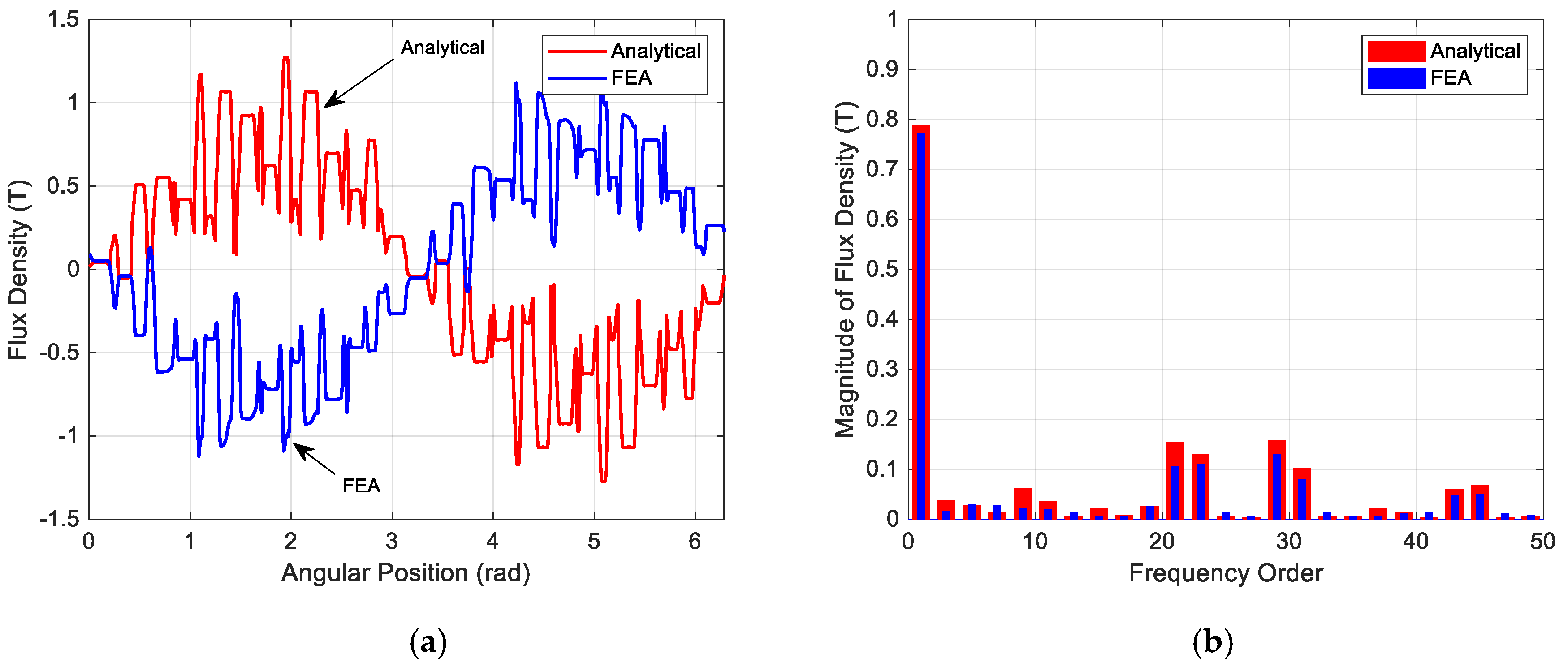
2. Space Harmonics in the Air Gap Magnetic Field

Any symmetric m-phase ( m ) induction machine has a space displacement between any two successive stator phases equal to 2 π / m . The stator winding is designed as sinusoidally distributed as possible and is fed with balanced m-phase sinusoidal currents. The combined effect is equivalent to having the same winding excited with a constant current and rotating at the stator frequency (rotating field established). Ideally, when the number of stator slots Q 1 approaches infinity ( Q 1 ) , and no iron core saturation will appear, the winding forms a sinusoidal magnetic field (or magneto-motive force, mmf) in the air gap δ . However, the practical windings are placed into the finite number of slots and the machines’ core always experiences saturation; therefore, the resulting magneto-motive force has rather stepped than sinusoidal curve. This complex curve can be described with Fourier series of mmf waves called space harmonics. The orders of these harmonics are usually marked with symbol ν .

Synthesis of Air Gap Magnetic Field Formed by Symmetrically Distributed Windings

As shown in [29], a hypothetical single-coil winding, fed by a time-varying sinusoidal current, produces mmf having rectangular waveform according to (1). The equation considers constant air gap permeance independent of angular position (even air gap) and the iron core made of steel having infinite relative permeability.
H x ( α ) = 2 i π δ ν = 1 1 ν s i n ( ν α y 2 ) c o s ( ν [ α ( ξ + ( x 1 ) ) α 1 ] ) ,   α y = β π
In (1), β < 0 ; 1 > represents the shortening of the winding coil pitch (chorded winding), i is the current content in the slot, α is mechanical angle measured in the air gap periphery, ξ is position of the coil group origin given in slots number and α 1 = 2 π / Q 1 .
For symmetric m-phase winding distributed in Q 1 stator slots, creating 2p magnetic poles, we can introduce q = Q 1 / 2 p m as the number of slots per phase per pole. Hence, the field produced by respective coils in group of q coils can be described using (2). For further analysis, it is reasonable to consider only the basic two-pole winding, therefore we always assume that 2p = 2.
H 1 ( α ) = 2 i π δ ν = 1 1 ν s i n ( ν α y 2 ) c o s ( ν α ξ α 1 ) H 2 ( α ) = 2 i π δ ν = 1 1 ν s i n ( ν α y 2 ) c o s ( ν [ α ( ξ + 1 ) α 1 ] ) H 3 ( α ) = 2 i π δ ν = 1 1 ν s i n ( ν α y 2 ) c o s ( ν [ α ( ξ + 2 ) α 1 ] ) H q ( α ) = 2 i π δ ν = 1 1 ν s i n ( ν α y 2 ) c o s ( ν [ α ( ξ + ( q 1 ) ) α 1 ] )
The summation of particular fields (2) gives resulting mmf (3) generated by a group of q coils corresponding to the coil group of one stator phase.
H g r o u p ( α ) = 2 i π δ ν = 1 [ 1 ν s i n ( ν α y 2 ) k = 1 q [ c o s ( ν [ α ( ξ + ( k 1 ) ) α 1 ] ) ] ]
Simplifying (3) we obtain more useful Equation (4).
H g r o u p ( α ) = 2 q i π δ ν = 1 [ 1 ν s i n ( ν α y 2 ) s i n ( q α 1 2 ν ) q   s i n ( α 1 2 ν )   c o s ( α ν ν ( q 1 + 2 ξ ) α 1 2 ) ]
From (4), it is easy to find the resulting mmf waveform generated by any symmetric m-phase distributed winding designed with integer q. We consider twice the number of mathematical phases m = 2 m , therefore ξ = ( k 1 ) 2 q is substituted for the “plus” phases (A, B, C, D, E, …), and ξ = m q + ( k 1 ) 2 q is substituted for the “minus” phases (A’, B’, C’, D’, E’, …). The input current with angular frequency ω 1 flowing through the k-th stator phase is defined as (5):
i k ( t ) = I k m s i n ( ω 1 t k 1 m   2 π )
Hence by combination (4) with (5) we obtain (6):
H m p h a s e ( α ) = 4 q π δ I k m ν = 1 [ 1 ν s i n ( ν α y 2 ) s i n ( ν m q α 1 2 ) s i n ( q α 1 2 ν ) q   s i n ( α 1 2 ν ) k = 1 m [ s i n ( ν 2 α + ( 1 k   4 q ) α 1 2 ) s i n ( ω 1 t k 1 m   2 π ) ] ]
Equation (6) can be further modified into (7) to calculate with given coil turns number per slot N carrying the input current I 2 . For single-layer winding, N/2 must be used instead of N.
H m p h a s e ( α ) = 4 2 N I q π δ ν = 1 [ 1 ν s i n ( ν α y 2 ) s i n ( ν m q α 1 2 ) s i n ( q α 1 2 ν ) q   s i n ( α 1 2 ν ) k = 1 m [ s i n ( ν 2 α + ( 1 k   4 q ) α 1 2 ) s i n ( ω 1 t k 1 m   2 π ) ] ]
As an example, for the three-phase winding, (7) results in (8),
H 3 p h a s e ( α ) = 4 2 N I q π δ ν = 1 [ 1 ν s i n ( ν α y 2 ) s i n ( ν m q α 1 2 ) s i n ( q α 1 2 ν ) q   s i n ( α 1 2 ν ) [ s i n ( ν 2 α + ( 1 4 q ) α 1 2 ) s i n ( ω 1 t ) + s i n ( ν 2 α + ( 1 8 q ) α 1 2 ) s i n ( ω 1 t 2 3 π ) + s i n ( ν 2 α + ( 1 12 q ) α 1 2 ) s i n ( ω 1 t 4 3 π ) ] ]
For the five-phase winding we have (9),
H 5 p h a s e ( α ) = 4 2 N I q π δ ν = 1 [ 1 ν s i n ( ν α y 2 ) s i n ( ν m q α 1 2 ) s i n ( q α 1 2 ν ) q   s i n ( α 1 2 ν ) [ s i n ( ν 2 α + ( 1 4 q ) α 1 2 ) s i n ( ω 1 t ) + s i n ( ν 2 α + ( 1 8 q ) α 1 2 ) s i n ( ω 1 t 2 5 π ) + s i n ( ν 2 α + ( 1 12 q ) α 1 2 ) s i n ( ω 1 t 4 5 π ) + s i n ( ν 2 α + ( 1 16 q ) α 1 2 ) s i n ( ω 1 t 6 5 π ) + s i n ( ν 2 α + ( 1 20 q ) α 1 2 ) s i n ( ω 1 t 8 5 π ) ] ]
And the seven-phase winding will generate field according to (10):
H 7 p h a s e ( α ) = 4 2 N I q π δ ν = 1 [ 1 ν s i n ( ν α y 2 ) s i n ( ν m q α 1 2 ) s i n ( q α 1 2 ν ) q   s i n ( α 1 2 ν ) [ s i n ( ν 2 α + ( 1 4 q ) α 1 2 ) s i n ( ω 1 t ) + s i n ( ν 2 α + ( 1 8 q ) α 1 2 ) s i n ( ω 1 t 2 7 π ) + s i n ( ν 2 α + ( 1 12 q ) α 1 2 ) s i n ( ω 1 t 4 7 π ) + s i n ( ν 2 α + ( 1 16 q ) α 1 2 ) s i n ( ω 1 t 6 7 π ) + s i n ( ν 2 α + ( 1 20 q ) α 1 2 ) s i n ( ω 1 t 8 7 π ) + s i n ( ν 2 α + ( 1 24 q ) α 1 2 ) s i n ( ω 1 t 10 7 π ) + s i n ( ν 2 α + ( 1 28 q ) α 1 2 ) s i n ( ω 1 t 12 7 π ) ] ]
The air gap flux density distribution is then obtained by applying (11).
B m p h a s e ( α ) = μ 0 H m p h a s e ( α )
Previous approach assumes a uniform air gap δ , which makes the analyzed air gap field corresponding to the mmf waveform generated by the winding. The stator and the rotor surfaces are slotted in a practical machine, and therefore, the air gap permeance varies along with the machine periphery and generates additional flux waves. Hence, the air gap appears to be slightly wider than its real mechanical size. The widening of the air gap is traditionally considered via Carter’s factor k c [30]. As proposed in [29], this can be considered by introducing a fictive air gap (12),
δ ( α ) = 1 f 1 ( α ) + 1 f 2 ( α ) δ 0
where δ 0 represents the initially assumed (even) air gap, and the functions f 1 ( α ) and f 2 ( α ) introduce the stator and the rotor slotting, respectively (13).
f 1 ( α ) = a 0 ν = 1 a v cos ( ν Q 1 α ) , a 0 = 1 k c 1 δ 0 f 2 ( α ) = b 0 ν = 1 b v cos ( ν Q 2 α ) , b 0 = 1 k c 2 δ 0
The Carter factors k c 1 and k c 2 , important to (13), are determined from given stator/rotor slot pitches t d 1 and t d 2 using (14),
k c 1 = t d 1 t d 1 γ 1 δ 0 , k c 2 = t d 2 t d 2 γ 2 δ 0
where γ 1 , 2 comes from (15).
γ 1 , 2 = 4 π [ b 01 , 02 2 δ 0 a t a n ( b 01 , 02 2 δ 0 ) l n 1 + ( b 01 , 02 2 δ 0 ) 2 ]
Parameters b 01 and b 02 represent the slots opening of the stator and the rotor, respectively. To complete substitution into (13), we only need to calculate the values of a v and b v according to (16),
a v = 4 β 1 π δ 0 ν [ 1 2 + ( b 01 t d 1 ν ) 2 0.78 2 ( b 01 t d 1 ν ) 2 ] s i n ( 1.6 π b 01 t d 1 ν ) b v = 4 β 2 π δ 0 ν [ 1 2 + ( b 02 t d 2 ν ) 2 0.78 2 ( b 02 t d 2 ν ) 2 ] s i n ( 1.6 π b 02 t d 2 ν )
where β 1 and β 2 come from (17).
β 1 = 1 2 1 2 b 01 [ b 01 ( 1 k c 1 1 ) ] , β 2 = 1 2 1 2 b 02 [ b 02 ( 1 k c 2 1 ) ]
However, by substitution (12) into (7), we find that for some chosen q the “tooth-to-tooth” synchronization of both waves is not fully observed, and therefore, it is necessary to introduce a correction factor (angular displacement) for one of the coordinate systems. Hence, Equation (7) should be rewritten into (18).
H m p h a s e ( α ) = 4 2 N I q π δ ( α ) ν = 1 [ 1 ν s i n ( ν α y 2 ) s i n ( ν m q α 1 2 ) s i n ( q α 1 2 ν ) q   s i n ( α 1 2 ν ) k = 1 m [ s i n ( ν 2 α + ( 1 k   4 q ) α 1 α s h i f t 2 ) s i n ( ω 1 t k 1 m   2 π ) ] ]
For any full-pitch winding with odd q, we select α s h i f t = 2 π / Q 1 in (17), and analogously, for winding with even q, we apply α s h i f t = 0 . In case of chorded winding, we use either α s h i f t = 2 π / Q 1 for q = 1, 2, 5, 6, 9, 10, … or α s h i f t = 0 for q = 3, 4, 7, 8, 11, 12, …. To obtain the flux density distribution, formula B m p h a s e ( α ) = μ 0 H m p h a s e ( α ) . must be applied to all equations relating to the air gap magnetic field strength distribution.
For the better understanding, we will analyze the air gap magnetic field for three various “fictive” single-layer (or double-layer) windings, considering slotless (7) and slotted (18) motor geometry. This situation is close to no-load motor operation (zero torque and zero rotor field). First, the flux density generated by a three-phase, full-pitched, winding having Q 1 = 30 , Q 2 = 22 , 2 p = 2 and q = 5 is shown in Figure 1. The left-side figure presents the flux density distribution as it depends on the air gap angular position, and the right-side figure shows the resulting frequency spectrum. While the red curve depicts the field considering smooth air gap with no slots present on the stator or the rotor, the blue curve shows the situation for slotted lamination.
Second, the flux density formed by a five-phase, full-pitched, winding having Q 1 = 30 , Q 2 = 22 , 2 p = 2 and q = 3 is shown in Figure 2.
Finally, the flux density formed by a seven-phase, full-pitched, winding having Q 1 = 28 , Q 2 = 22 , 2 p = 2 and q = 2 is shown in Figure 3.
The comparison between discussed windings shows that the motor having more phases can form a smoother magnetic field (lower content of harmonics) than the less phases motor even if it has similar slots number. Hence, this motor can generate less torque ripple, distinguishes lower THDi and can reduce noise. For air gap flux density spectrum, we can formulate several conclusions generally valid for any distributed multiphase winding having integer q.
First, the spectrum includes all harmonics orders calculated from (19). When the operator “+” is used, the relevant harmonic generates mmf travelling the air gap together with the fundamental harmonic but ν -times slower, and to the contrary, the operator “−” gives harmonics producing waves traveling the air gap in opposite direction (also ν -times slower).
ν = 2 m c ± 1 , c
Second, the spectrum also includes frequency orders called “step” harmonics obtained from (20). They are present in the spectrum mainly due to the fact that the winding is placed in a finite number of stator slots. The stator “slot” harmonics have therefore the same orders as have the “step” harmonics, and hence, they both overlap in the frequency spectrum. The “step” harmonics have the winding factor of the same size as the fundamental harmonic.
ν 1 s t e p = ν 1 s l o t = c Q 1 p ± 1 , c .
Besides the “step” harmonic orders, the air gap flux density includes also the rotor “slot” harmonics (21).
ν 2 s l o t = c Q 2 p ± 1 , c
Third, as shown in (18) the winding factor considering straight rotor bars is still given by (22),
k w ν = s i n ( ν π β 2 ) s i n ( ν π m ) q   s i n ( ν π m q )
Hence the magnitude of ν -th harmonics can be calculated from fundamental harmonic using (23).
B ν = B 1 ν   k w ν
According to previous results, the harmonic orders of the “step” and the stator “slot” harmonics interact and modify the original order (20) magnitudes. Considering only the interaction between the very first “step” and “slot” harmonic orders calculated from (20) when c = 1 , then the resulting magnitude of (24),
ν = Q 1 p 1
Becomes, according to (25),
B ν = B 1 s t e p [ a 1 2 a 0 Q 1 p p + 1 ]
Moreover, analogously, for (26),
ν = Q 1 p + 1
We obtain (27):
B ν = B 1 s t e p [ a 1 2 a 0 Q 1 + p p 1 ]
Into (25) and (27), we substitute from (13) for a 0 and from (16) for a 1 with applying ν = 1 . This gives us a rough estimate of analyzed harmonic amplitudes.
To demonstrate validity of the method, we can analyze (using FEA) the air gap magnetic field of real 3 kW five-phase induction motor corresponding to the case study shown in Figure 2. The motor geometry with magnetic distribution is shown on the left side of Figure 4. The right side of the same figure shows the resulting air gap flux density calculated using FEA and compared to given analytical approach. In order to compare comparable, the FEA considers no-load state (zero torque) and magnetic core composed of linear steel having very high relative permeability ( μ r = 10 4 ).
For the no-load operation, the proposed analytical method of air gap space harmonics prediction works well, but it may fail when the machine operates under load condition. In this case, the induced voltage generates a current flowing through the rotor, which generates its own magnetic field. This rotor field interacts with the original stator field, which in turn produces torque. As the air gap flux density combines both the stator and the rotor magnetic fields, the resulting curve is deformed as compared to the no-load air gap magnetic field. An example of the situation is shown in Figure 5. The motor (from Figure 4) operates under load (3 kW), and its magnetic field is calculated using nonlinear (steel with μ r = f ( I ) ) transient analysis to reach as high accuracy as possible. Figure 5 on the left side represents the instantaneous distribution of the magnetic field in the motor cross-section, and the right frame shows the corresponding air gap flux density curve.
The no-load and the loaded operation states are compared graphically in Figure 6 by composing the two curves (taken from Figure 4 and Figure 5) in one graph. The red line (taken from Figure 4) shows the flux density curve corresponding to the no-load operation, and the blue curve (taken from Figure 5) shows the magnetic field corresponding to the operation under load.
As obvious from the right side of Figure 6, the frequency spectrum of the loaded flux density includes harmonics that have not been predicted yet, and which are mainly caused by the rotor field presence and by saturation of the motor magnetic core.
The saturated motor flats the air gap magnetic field according to the BH curve of steel used for the motor construction. As the field is a periodic odd function, the spectrum will contain group of “saturation” harmonics (28), even if the stator and rotor are considered to be slot-less.
ν s a t u r a t i o n = 2 ( c 1 ) + 1 , c
Although we classify these harmonics as space harmonics, their speed and direction do not follow the previous rules. Analyzing the air gap flux density, we find that the resulting (flattened) mmf travels the air gap with a constant shape (slots are not considered), which means that the harmonics created by the saturation must travel at the same speed and in the same direction as the fundamental wave. As a result, these harmonics contribute to the machine’s useful torque.
Since these harmonics travel through the air gap synchronously with the fundamental harmonic, their slip must be the same as slip of the fundamental harmonic. Currents induced into the rotor bars will therefore include harmonics corresponding to (28).
Rotor time harmonics can be calculated either by analytical approach based on methodology described in [31] or by using FEA. The authors of [31] represented a squirrel-cage rotor by a star-connected winding with transformation of the end rings into stars. From pre-calculated saturation harmonics [30,31], they derived the induced voltage per leg of the proposed equivalent diagram and calculated the harmonic currents using transformed bar resistance and reactance.
An example relating to motor in Figure 5 is seen in Figure 7, where the left side represents the time dependency of the current (calculated from FEA) flowing through the bar, and the right side shows its frequency spectrum.
Analogously to (1), we can find the magnetic field (29) generated by the kth single rotor bar carrying the current i k .
B b a r k ( α ) = i k μ 0 π δ ( α ) ν = 1 1 ν s i n ( ν [ α ( k 1 ) α 1 ] )
A symmetrically manufactured rotor, having bars evenly distributed along the air gap, generates magnetic field of opposite direction to the field formed by the stator. Considering sinusoidal rotor current distribution, Equation (30) describes the resulting rotor field. Here, I 2 m represents the bar current magnitude.
B c a g e ( α ) = μ 0 π δ ( α ) I 2 m k = 1 Q 2 [ s i n ( ω t p k 1 Q 2 2 π ) ν = 1 1 ν s i n ( ν [ α ( k 1 ) α 1 ] ) ]
As shown in Figure 7, the bar current includes, besides the fundamental harmonic component, also an amount of additional time harmonics deforming the previously assumed sinusoidal current wave. Based on this, (30) should be rewritten in (31) to consider n rotor time harmonics.
B c a g e ( α ) = μ 0 π δ ( α ) k = 1 Q 2 [ μ = 1 n [ I μ s i n ( μ [ ω t p k 1 Q 2 2 π φ i μ ] φ s h i f t ) ] ν = 1 1 ν s i n ( ν [ α ( k 1 ) α 1 ] ) ]
New parameter φ i μ represents the phase shift of μ th time harmonic component, and φ s h i f t is the angle measured between the stator and the rotor mmfs obtained analyzing the machines equivalent circuit [32,33]. Final magnetic field curve (see Figure 8) is then given as the difference between the stator and the rotor fields, i.e., B m p h a s e ( α ) B c a g e ( α ) .
The left side of Figure 8 compares the flux density waveform obtained using proposed analytical approach (red line) to the one derived from FEA (blue line). To ensure better clarity, the blue line is inverted. The right side of Figure 8 shows comparison between harmonic spectrum corresponding to both waveforms.
The results show good agreement between the proposed method and FEA and is therefore an effective way to air gap flux density prediction in any multiphase induction motor having distributed winding with integer slots number per pole per phase.

3. Time Harmonics in Multiphase Winding

For common three-phase industrial line-started induction machines, the significant source of non-harmonic voltage is mainly the power supply imbalance. Multiphase motors are usually powered from frequency converters used for easy and energy efficient speed control. The inverters (especially the voltage-types) generate voltage having either rectangular or pulsed shape. Thus, its spectrum contains the amount of harmonics μ dependent on the load and the pulse width modulation settings. Non-harmonic power supply can cause parasitic torque ripples, vibrations, increased noise, increased voltage stress of the insulation system and also can generate higher I2R winding losses due to harmonic currents.
Sometimes, particularly when talking about multiphase motors, the time harmonics are injected into the power supply in order to increase torque per ampere. The extra torque is obtained due to the fact that the flux distribution in the air gap is flattened so that the saturation can be avoided for a wider operational range.

3.1. Harmonics Creating 2p Number of Pole Pairs

Operational properties of significant time harmonics and their influence on the motor can be analyzed composing a time-varying phasor diagram showing the magnetic field (32).
F m p h a s e   μ = F m μ   k = 1 m [ c o s ( α k 1 m 2 π ) c o s ( μ ω 1 t μ k 1 m 2 π ) ]
Sine wave current, represented by the second multiplier in the summation, flowing in each of m stationary coils, represented by the first multiplier, produces m sine varying magnetic fields perpendicular to the rotation axis. The m magnetic fields add as vectors to produce a single rotating magnetic field F m p h a s e   μ .
For example, the fundamental harmonic component working in three-phase motor generates positive sequence field with amplitude (33).
F 3 p h a s e   1 = F m 1 1 2 [ c o s ( α ω 1 t ) + c o s ( α + ω 1 t ) ] + F m 1 1 2 [ c o s ( α ω 1 t ) + c o s ( α + ω 1 t 4 3 π ) ] + F m 1 1 2 [ c o s ( α ω 1 t ) + c o s ( α + ω 1 t 8 3 π ) ] = = F m 1 3 2 c o s ( α ω 1 t )
Similarly, we can derive (34) for the 5th and 7th harmonic components obtaining the negative and the positive sequence waves, respectively.
F 3 p h a s e   5 = F a 5 + F b 5 + F c 5 = = F m 5 3 2 c o s ( α + 5 ω 1 t ) F 3 p h a s e   7 = F a 7 + F b 7 + F c 7 = = F m 7 3 2 c o s ( α 7 ω 1 t ) .
Performing analyses for randomly chosen motors and harmonics, e.g., the five-phase motor fed by 5th harmonics and seven-phase motor fed by 7th harmonics, we get (35).
F 5 p h a s e   5 = F m 5   5 2 c o s ( α + 5 ω 1 t ) F 7 p h a s e   7 = F m 5   7 2 c o s ( α 7 ω 1 t )
Normally, the literature recognizes the harmonic content in the voltage curve of the inverter following rule (36),
μ = 2 m c ± 1 , c
However, in case of harmonic injection drives, the converter can generate any harmonic we need; therefore, (36) could be rewritten in more general (37).
μ = m c ± 1 , c
Based on the previous analyses, we may conclude that by applying the operator “+” on (37), the resulting harmonics create waves traveling the air gap together with the fundamental one, but their speed is μ -times higher. Moreover, to the contrary, the operator “−” gives harmonics producing waves passing through the air gap again μ -times faster but now in opposite direction. Under perfectly balanced conditions, all these harmonics produce rotating magnetic fields having constant amplitudes (38) and angular speeds in time, so they form circular shaped fields.
F m p h a s e   μ = F m μ m 2

3.2. Harmonics Creating Higher Number of Pole Pairs than 2p

For any harmonic order originating from (39), the application of (32) gives always zero value. In addition, all phase currents (related to the analyzed harmonic) are in phase with each other and therefore generate zero sequence (non-rotating) field.
μ = m c , c
When injecting subharmonic ( μ ), the resulting magnetic field changes the amplitude and angular speed in time, which deforms originally circular field into elliptical. In extreme cases (40), the field takes the pulsating form having zero translation speed against the air gap and generates losses, produces noise and causes homopolar magnetic saturation.
μ = m 2 + m ( c 1 ) , c .
The situation becomes more complicated when studying integer harmonic orders that are not predicted, neither by (37) nor (39). Substituting into (32) we get zero values even though they are harmonics generating fields with different phase shift relative to each other. Therefore, they produce magnetic field passing through the air gap with nonzero speed. For five-phase motor, we find those harmonics from (41),
μ = m ( c 1 ) ± 2 , c
However, the seven-phase motor includes, besides (41), also (42).
μ = m ( c 1 ) ± 3 , c
Hence, in case of nine-phase motor we must apply (41) to (43).
μ = m ( c 1 ) ± 4 , c
All these harmonics produce a magnetic field with higher number of pole pairs than generated by the fundamental harmonic. This is due to the specific “time” re-assembling of the stator phases ( μ -multiplication of individual phase shifts) while keeping the same winding mechanical distribution. This in turn forms a new winding with completely new Görges diagram [30] producing higher number of pole-pairs. Figure 9 shows the example of the 3rd harmonic (magnitude equals to the fundamental) injected into the five-phase motor discussed previously in Figure 5 ( Q 1 = 30 , Q 2 = 22 ,   2 p = 2 , q = 3).
As it forms 3 × 2 p number of poles, the speed must be the same as that developed by the fundamental harmonic. Similar behavior can be observed also for the 3rd and 5th current harmonic in seven-phase motor and for the 3rd, 5th and 7th harmonic in nine-phase motor (see left side of Figure 10).
Amplitudes of individual harmonics could be derived from new Görges diagram. As these amplitudes are defined by half ampere-turns corresponding to one magnetic pole, we may calculate them from the ampere-turns that belong to one pole pitch. These specific “pole-creating” harmonics generate in the air gap space harmonics having the same order ( μ = ν ), so we can consider the pole pitch to be μ -times shorter as compared to the fundamental. Hence, only (44) coil turns contribute to the final value of individual harmonic amplitude.
q m 2 μ N
With multiplication (44) by the mean value of the stator current I μ we obtain the resulting mmf from (45).
H μ m a g = q δ 0 m μ N I μ π 2 , μ = ν
Considering the winding factor of μ -th harmonic component (still we assume μ = ν ), the magnitude of the air gap flux density is then (46).
B μ m a g = μ 0 q δ 0 m π N k w ν μ I μ 2 , μ = ν
As demonstrated in the right side of the figure, other harmonics (excluding (37) and (39)) may create either circular or the elliptical fields traveling in different directions and speeds.
Table 1 shows the same overview but extended by nine-phase machines. Column “poles” gives number of magnetic poles created by the particular harmonic component, column “sequence” shows the traveling direction (or field character) and column “speed” specifies the velocity relative to the fundamental wave. The field character shows whether the mmf travels against the air gap (“+” or “−”) or pulsates (“puls.”) with zero speed.
Following this, we can construct Figure 11, Figure 12 and Figure 13 to give graphical demonstration of the harmonics’ operational influence.
As obvious, there is an amount of harmonics that can create magnetic field traveling the air gap with the same speed and direction that travels the fundamental wave (color marked). These harmonics are usually being injected in order to increase the torque.

4. Conclusions

From the research results, it is evident that a motor having a higher number of phases can produce a more sinusoidal magnetic field than the motor having a smaller number of phases, even if it has a similar number of slots. Hence, by increasing the number of phases, the torque harmonics decrease. For distributed multiphase winding with integer q, we can conclude following rules.
First, the spectrum of the air gap flux density includes harmonic orders obtained from (19). These harmonics generate fields traveling the air gap in a different direction (according to operator used) and speed ( ν -times lower than fundamental).
Second, as the windings are physically placed in slots, the spectrum includes significant orders called “step” harmonics (20) having the same winding factor as calculated for fundamental harmonic. The real “slot” harmonics are obtained also from (20), and therefore, their orders overlap (interact) with “step” harmonics. As a consequence, this interaction modifies original magnitudes of (20), and resulting air gap flux density is influenced.
Third, as shown in (18), the winding factor considering straight rotor bars is still given by (22), hence the magnitude of ν -th harmonics can be calculated from fundamental harmonic using (23).
Fourth, the injection of time harmonics can produce magnetic field having even more than 2p magnetic pole-pairs. For any harmonic order originating from (39), the application of (32) produces zero value, therefore zero sequence (non-rotating) field.
Fifth, considering subharmonics ( μ ), the resulting magnetic field deforms its originally circular shape into an elliptical one. In extreme case (40), the field pulsates in only one axis forming a kind of homopolar field. When studying integer harmonic orders that are not predicted, neither by (37) nor (39), the substitution into (32) gives zero values even though they are harmonics establishing field waves passing through the air gap win non-zero speed. All these harmonics produce magnetic field having more magnetic pole-pairs than 2p. Some of them (e.g., 3rd, 5th and 7th harmonic in nine-phase motor) can travel the air gap with the same speed as developed by the fundamental harmonic and may be therefore injected in order to increase the torque.

Author Contributions

Conceptualization, V.K. and R.C.; methodology, V.K.; software, V.K.; finite element analyses, R.C. and Z.F.; formal analysis, V.K.; writing—original draft preparation, V.K.; writing—review and editing, V.K., R.C., Z.F. and B.S.; visualization, V.K.; supervision, Z.F. and B.S. All authors have read and agreed to the published version of the manuscript.

Funding

This research was funded by the Ministry of Education, Youth and Sports of the Czech Republic under the project OP VVV Electrical Engineering Technologies with High-Level of Embedded Intelligence CZ.02.1.01/0.0/0.0/18_069/0009855 and by funding program of the University of West Bohemia number SGS-2018-009. This research was also funded by Slovak Research and Development Agency under the contract No. APVV-18-0436.

Conflicts of Interest

The authors declare no conflicts of interest.

References

  1. Tie, S.F.; Tan, C.W. A review of energy sources and energy management system in electric vehicles. Renew. Sustain. Energy Rev. 2013, 20, 82–102. [Google Scholar] [CrossRef]
  2. Chau, K.T.; Wong, Y.S.; Chan, C.C. An overview of energy sources for electric vehicles. Energy Convers. Manag. 1999, 40, 1021–1039. [Google Scholar] [CrossRef]
  3. Su, W.; Eichi, H.; Zeng, W.; Chow, M.Y. A survey on the electrification of transportation in a smart grid environment. IEEE Trans. Ind. Inform. 2012, 8, 1–10. [Google Scholar] [CrossRef]
  4. Emadi, A.; Lee, Y.J.; Rajashekara, K. Power electronics and motor drives in electric, hybrid electric, and plug-in hybrid electric vehicles. IEEE Trans. Ind. Electron. 2008, 55, 2237–2245. [Google Scholar] [CrossRef]
  5. Rajashekara, K. Present status and future trends in electric vehicle propulsion technologies. IEEE J. Emerg. Sel. Top. Power Electron. 2013, 1, 3–10. [Google Scholar] [CrossRef]
  6. Chan, C.C. The state of the art of electric, hybrid, and fuel cell vehicles. Proc. IEEE 2007, 95, 704–718. [Google Scholar] [CrossRef]
  7. Zhu, Z.Q.; Howe, D. Electrical machines and drives for electric, hybrid, and fuel cell vehicles. Proc. IEEE 2007, 95, 746–765. [Google Scholar] [CrossRef]
  8. Pellegrino, G.; Vagati, A.; Boazzo, B.; Guglielmi, P. Comparison of induction and PM synchronous motor drives for EV application including design examples. IEEE Trans. Ind. Appl. 2012, 48, 2322–2332. [Google Scholar] [CrossRef] [Green Version]
  9. Popescu, M.; Goss, J.; Staton, D.A.; Hawkins, D.; Chong, Y.C.; Boglietti, A. Electrical vehicles—Practical solutions for power traction motor systems. IEEE Trans. Ind. Appl. 2018, 54, 2751–2762. [Google Scholar] [CrossRef] [Green Version]
  10. Yang, Z.; Shang, F.; Brown, I.P.; Krishnamurthy, M. Comparative study of interior permanent magnet, induction, and switched reluctance motor drives for EV and HEV applications. IEEE Trans. Transp. Electrif. 2015, 1, 245–254. [Google Scholar] [CrossRef]
  11. Boldea, I.; Tutelea, L.N.; Parsa, L.; Dorrell, D. Automotive electric propulsion systems with reduced or no permanent magnets: An overview. IEEE Trans. Ind. Electron. 2014, 61, 5696–5711. [Google Scholar] [CrossRef]
  12. Kowal, A.; Arahal, M.R.; Martin, C.; Barrero, F. Constraint satisfaction in current control of a five-phase drive with locally tuned predictive controllers. Energies 2019, 12, 2715. [Google Scholar] [CrossRef] [Green Version]
  13. Resa, J.; Cortes, D.; Marquez-Rubio, J.F.; Navarro, D. Reduction of induction motor energy consumption via variable velocity and flux references. Electronics 2019, 8, 740. [Google Scholar] [CrossRef] [Green Version]
  14. Zamani, J.S. Computer simulation of converter fed synchronous machine drives containing space harmonics. In Proceedings of the International Conference on Power Electronics, Drives and Energy Systems for Industrial Growth, New Delhi, India, 8–11 January 1996; pp. 944–950. [Google Scholar]
  15. Fu, J.-R.; Lipo, T.A. Disturbance-free operation of a multiphase current-regulated motor drive with an opened phase. IEEE Trans. Ind. Appl. 1994, 30, 1267–1274. [Google Scholar] [CrossRef]
  16. Zhao, Y.; Lipo, T.A. Modeling and control of a multi-phase induction machine with structural unbalance. IEEE Trans. Energy Convers. 1996, 11, 578–584. [Google Scholar] [CrossRef]
  17. Levi, E.; Bojoi, R.; Profumo, F.; Toliyat, H.A.; Williamson, S. Multiphase induction motor drives—A technology status review. IET Electr. Power Appl. 2007, 1, 489–516. [Google Scholar] [CrossRef] [Green Version]
  18. Toliyat, H.A.; Lipo, T.A. Analysis of concentrated winding induction machines for adjustable speed drive applications-experimental results. IEEE Trans. Energy Convers. 1994, 9, 695–700. [Google Scholar] [CrossRef]
  19. Abdel-Khalik, A.S.; Masoud, M.I.; Williams, B.W. Improved flux pattern with third harmonic injection for multiphase induction machine. IEEE Trans. Power Electron. 2012, 27, 1563–1578. [Google Scholar] [CrossRef]
  20. Duran, M.J.; Salas, F.; Arahal, M.R. Bifurcation analysis of five-phase induction motor drives with third harmonic injection. IEEE Trans. Ind. Electron. 2008, 55, 2006–2014. [Google Scholar] [CrossRef]
  21. Lyra, R.O.C.; Lipo, T.A. Torque density improvement in a six-phase induction motor with third harmonic current injection. IEEE Trans. Ind. Appl. 2002, 38, 351–1360. [Google Scholar] [CrossRef]
  22. Abdel-Khalik, A.S.; Masoud, M.I.; Ahmed, S.; Massoud, A.M. Effect of current harmonic injection on constant rotor multiphase induction machine stators: A comparative study. IEEE Trans. Ind. Appl. 2012, 48, 2002–2013. [Google Scholar] [CrossRef]
  23. Ferkova, Z.; Kindl, V. Influence of skewed squirrel cage rotor with intermediate ring on magnetic field of air gap in induction machine. Electr. Eng. 2017, 23, 26–30. [Google Scholar] [CrossRef] [Green Version]
  24. Orság, O.; Rusnok, S.; Sobota, P.; Kačor, P. Influence of rotor slot shape on the parameters of induction motor. In Proceedings of the 2017 IEEE International Conference on Environment and Electrical Engineering and the 2017 IEEE Industrial and Commercial Power Systems Europe (EEEIC/I&CPS Europe), Milan, Italy, 6–9 June 2017; pp. 1–6. [Google Scholar]
  25. Bernat, P.; Kacor, P. Operational non-contact diagnostics of induction machine based on stray electromagnetic field. Commun. Sci. Lett. Univ. Zilina 2015, 17, 89–94. [Google Scholar]
  26. Alger, P.L. The Nature of Polyphaser Induction Machines; Wiley: Hoboken, NJ, USA, 1951. [Google Scholar]
  27. Neto, L.M.; Camacho, J.R.; Salerno, C.H.; Alvarenga, B.P. Analysis of a three-phase induction machine including time and space harmonic effects: The a, b, c reference frame. IEEE Trans. Energy Convers. 1999, 14, 80–85. [Google Scholar] [CrossRef]
  28. Stincescu, R.B.; Viarouge, P.; Cros, J.; Kamwa, I. A general approach of space and time harmonics interactions in induction motors. In Proceedings of the IEEE International Electric Machines and Drives Conference, Seattle, WA, USA, 3–12 May 1999; pp. 366–368. [Google Scholar] [CrossRef]
  29. Heller, B.; Hamata, V. Harmonic Field Effects in Induction Machines; Elsevier Science Ltd.: Amsterdam, The Netherlands, 1977; ISBN 9780444998569. [Google Scholar]
  30. Liao, Y.; Lipo, T.A. Effect of saturation third harmonic on the performance of squirrel-cage induction machines. Electr. Mach. Power Syst. 1994, 22, 155–171. [Google Scholar] [CrossRef]
  31. Lee, C.H. Saturation 597–harmonics of polyphase induction machines. Trans. Am. Inst. Electr. Eng. Part III Power Appar. Syst. 1961, 80, 603. [Google Scholar] [CrossRef]
  32. Pyrhönen, J.; Jokinen, T.; Hrabovcova, V. Design of Rotating Electrical Machines, 2nd ed.; John Wiley & Sons Ltd.: Chichester, UK, 2014; ISBN 978-1-118-58157-5. [Google Scholar]
  33. Laksar, J.; Sobra, J.; Veg, L. Numerical calculation of the effect of the induction machine load on the air gap magnetic flux density distribution. In Proceedings of the 2017 18th International Scientific Conference on Electric Power Engineering (EPE), Kouty nad Desnou, Czech Republic, 17–19 May 2017; pp. 1–6. [Google Scholar] [CrossRef]
Figure 1. (a) Air gap field generated by 3-phase winding; field distribution (left), (b) frequency spectrum (right).
Energies 13 00496 g001
Figure 2. (a) Air gap field generated by 5-phase winding; field distribution (left), (b) frequency spectrum (right).
Energies 13 00496 g002
Figure 3. (a) Air gap field generated by 7-phase winding; field distribution (left), (b) frequency spectrum (right).
Energies 13 00496 g003
Figure 4. (a) No-load flux density distribution inside the machine, (b) air gap flux density.
Energies 13 00496 g004
Figure 5. (a) Flux density distribution inside the machine under load, (b) air gap flux density.
Energies 13 00496 g005
Figure 6. (a) Comparison between no-load and loaded operational state; field distribution (b) from FEA, frequency spectrum (right).
Energies 13 00496 g006
Figure 7. (a) Time dependency of bar current (left) and (b) its harmonic spectrum (right).
Energies 13 00496 g007
Figure 8. (a) Final air gap flux density for motor operating under load condition; flux density distribution (left)—blue line inverted, (b) frequency spectrum (right).
Energies 13 00496 g008
Figure 9. (a) Stator phases re-assembling, (b) mmf for the fundamental and the 3rd harmonics.
Energies 13 00496 g009
Figure 10. Time harmonics acting in multiphase winding: (a) harmonics suitable for injection, (b) harmonics inappropriate for injecting.
Energies 13 00496 g010
Figure 11. Time harmonics effect demonstration in three-phase machines.
Energies 13 00496 g011
Figure 12. Time harmonics effect demonstration in five-phase machines.
Energies 13 00496 g012
Figure 13. Time harmonics effect demonstration in seven-phase machines.
Energies 13 00496 g013
Table 1. Time harmonics effect overview.
Five-Phase WindingSeven-Phase WindingNine-Phase Winding
μPolesSequenceSpeedPolesSequenceSpeedPolesSequenceSpeed
12p+12p+12p+1
23 × 2p2/35 × 2p2/57 × 2p2/7
2.53 × 2ppuls.0
33 × 2p+13 × 2p+13 × 2p+1
3.5 3 × 2ppuls.0
42p43 × 2p4/35 × 2p4/5
4.5 5 × 2ppuls.0
55 × 2pzero05 × 2p+15 × 2p+1
62p+62p63 × 2p6/3
73 × 2p7/37 × 2pzero07 × 2p+1
7.53 × 2ppuls.0
83 × 2p+8/32p+82p8
92p95 × 2p9/59 × 2pzero0
105 × 2pzero03 × 2p+10/32p+10

