Abstract
In recent years, residential rate consumptions have increased due to modern appliances which require a high level of electricity demands. Although mentioned appliances can improve the quality of consumers’ lives to a certain extent, they suffer from various shortcomings including raising the electricity bill as well as serious technical issues such as lack of balance between electricity generation and load disturbances. This imbalance can generally lead to the frequency excursion which is a significant concern, especially for low-inertia microgrids with unpredictable parameters. This research proposes an intelligent combination of two approaches in order to alleviate challenges related to the frequency control mechanism. Firstly, a learning-based fractional-order proportional-integral-derivative (FOPID) controller is trained by recurrent adaptive neuro-fuzzy inference (RANFIS) in the generation side during various operational conditions and climatic changes. In the following, a decentralized demand response (DR) programming in the load side is introduced to minimize consumption rate through controllable appliances and energy storage systems (ESSs). Furthermore, parameters uncertainties and time delay, which are generally known as two main concerns of isolated microgrids, are regarded in the frequency plan of a low-inertia microgrid including renewable energy sources (RESs), and energy storage systems (ESSs). Simulation results are illustrated in three different case studies in order to compare the performance of the proposed two methods during various operational conditions. It is obvious that the frequency deviation of microgrid can be improved by taking advantage of intelligent combination of both DR program and modern control mechanism.
1. Introduction
Over the last decades, renewable energy sources (RESs) have played a significant role in the generation of electricity and meeting consumers’ requirement due to recent environmental concerns as well as excessive changes in weather conditions. Although using distributed generations (DGs) like wind turbine generators (WTGs), solar panels, diesel engine generators (DEGs), and energy storage systems (ESSs) such as battery energy storage systems (BESSs) as well as flywheel energy storage systems (FESSs) has brought definite advantages to the ecosystem, this trend may contribute to some new challenges such as complexity in the frequency control mechanism, modern power systems weaknesses, and voltage instability [1,2]. As a result, among all the mentioned problems, keeping a balance between consumption rate and generation level is one of the main challenges in relation to the low-inertia microgrids (MGs) due to lack of rotational masses [3]. In fact, the coexistence of different types of renewable energy sources (RESs) with their various capabilities may lead to the several concerns associated with the control and stability of MGs [4]. It is important to note that the stand-alone type of microgrid may deteriorate these potential problems to a certain extent and yield more satisfactory performance during load disturbance and operational conditions in comparison to the conventional power plants topologies which have a close collaboration with other areas as well.
One of the detrimental effects of lack of balance between generation and load changes is frequency deviation which can be addressed by taking advantage of traditional and modern control mechanisms in an effective way [5,6]. Several studies have been published in the field of load frequency control during various operational conditions as well as structured uncertainties, so that these methods have mostly focused on the frequency control in the generation side of the power systems [7]. In reference [8], authors introduced a model predictive control (MPC) during frequency regulation of a power system in Nordic with some certain parameters. This presented control approach has been compared to the conventional automation generation control (AGC) scheme which includes proportional-integral (PI) controllers. In another paper [9], researchers proposed an optimal PSO-based PID frequency droop in a high penetrated wind farm power system. In order to resolve a non-linear problem of frequency response during some changes in parameters which occur in the power system suddenly, a new fuzzy-logic controller, which is tuned by an artificial bee colony (ABC) algorithm intelligently, has been suggested and the performance of this controller is compared to some conventional controllers as well [10]. Although obtained results of this paper illustrate a high level of improvement in the frequency response, the structured uncertainties appear not to regard practically in this research. In the following, an adaptive model predictive controller is introduced in order to mitigate the frequency deviation of a multi-area interconnected power system, when some renewable energy resources like photovoltaic (PV) panels play an active role in the generation side. In this system, lack of rotational masses like synchronous generators will create serious problems for the consumer as well as utility grid during various situations [11].
Due to the ever-increasing penetration of renewable energy sources (RESs) on the large scales, the stability of isolated MG during frequency excursion is becoming more challenging. Consequently, it seems that the tendency to deploy intelligent control methods, such as learning-based controller during parameters uncertainties can be a practical solution in the hybrid microgrids. Other paper emphasizes that the high rate of change of frequency (RoCoF) in isolated MGs require experts to deploy more intelligent methods for fast frequency response. As a result, a new frequency control approach based on the fuzzy-logic knowledge has been presented in a stand-alone hybrid microgrid including distributed generations [12]. In addition, an adaptive neuro-fuzzy controller is used in order to achieve an acceptable performance in the isolated microgrid including different kinds of distributed energy resources (DERs) such as wind turbine generators, solar panels as well as gas micro-turbines [13]. The acquired simulation results indicate that the proposed controller improve frequency behavior and decrease settling time in comparison to the conventional controllers as well. Another non-linear controller, which is called an optimized fractional-order proportional-integral-derivative (FOPID), has been proposed to regulate active power injection of fuel cell due to more satisfactory performance of this controller in comparison to the traditional ones. The outcome of mentioned research shows that the proposed controller provide a faster response and small overshoot compared to established controllers [14]. Recently, the tendency to deploy algorithm-based non-integer controller during load frequency control of microgrids have increased dramatically. In [15], authors have deployed butterfly optimization algorithm (BOA) for various types of integer and non-integer controllers and compared this assumed method with other commonplace algorithms such as PSO, FA, and whale optimization algorithm (WOA) in order to declare the efficiency of their proposed method. In another research, a developed heuristic optimization technique, which is called water cycle (WCA) algorithm, is suggested so as to adjust a FOPID controller for effective frequency control of renewable-based isolated two-area interconnected microgrid (ICμG) [16]. This paper illustrates the excellence of WCA-based FOPID controller during various situations with regard to different load disturbances, wind speed variation with real data, and solar irradiance.
In addition to the aforementioned approaches which are applied into the generation side of the low-inertia power systems, demand side management (DSM) methods can be deployed in order to alleviate the intermittent fluctuation of frequency response in the load side section. In fact, demand side management (DSM) methods have been promoted in order to allow the energy efficiency programs to lessen consumers’ electricity bill significantly [17]. Three indispensable sections of DSM includes observing, reducing and shifting the consumption rate [18,19]. Annual increment in the payment of consumers’ bills, which is the result of modern appliances, is taken into account as an important concern that should be resolved. In recent years, some DSM methods have been promoted by taking advantage of the plug-in hybrid electric vehicles (PHEVs), along with controllable appliances in several studies [20,21].
In [22], a comprehensive strategy is regarded as control mechanism by deploying the plug-in hybrid electric vehicles (PHEVs) and controllable gadgets in order to alleviate frequency excursion during some challenges in relation to the power plants. Moreover, Benysek et al. [23] have introduced a stochastic decentralized active demand response (DADR) for the frequency regulation of a power plants. The results of investigations have proved that the proposed stochastic DADR method in this paper, due to its high dynamic response in dealing with disturbance phenomena, can be deployed as part of both the primary and the supplementary load frequency control in modern power systems. Although simulation results depict that this proposed technique can improve the frequency deviation of power system, renewable energy sources don’t participate in the frequency mitigation. Moreover, different types of parametric uncertainty as well as communication delays are not considered in the presented model.
The main contribution of this paper is to combine learning-based fractional-order PID controller and decentralized demand response programming to mitigate the frequency deviation of a stand-alone microgrid during parametric uncertainties as well as changes in climatic patterns. Firstly, a learning-based FOPID controller is proposed in order to alleviate frequency deviation in the generation side of a hybrid microgrid which consist of wind turbine generator, photovoltaic panels, fuel cells, diesel engine generator as well as energy storage systems (ESSs). In the following step, a demand response program is introduced to moderate the load consumption pattern in the load side by taking advantage of controllable appliances and energy storage systems including plug-in hybrid electric vehicles (PHEVs) and battery energy storage systems (BESSs). In fact, the bidirectional devices like PHEV and BESS are used in order to enhance the efficiency of demand side management and increase the capability of low-inertia systems during frequency excursion considerably as well. During demand side management, a multi-objective function is defined which consist of two parts which has been formulated and resolved by mixed-integer nonlinear programming (MINLP) and mixed-integer quasi programming (MIQP) methods, respectively. The rest of the paper is organized as follows: methodology of the demand response program and FOPID controller is discussed in Section 2. Section 3 illustrates the results and effectiveness of the proposed approaches during the three various case studies. At the final stage, the conclusion is presented.
2. Methodology
The introduced methodology in order to improve frequency excursion to a great extent is consists of two fundamental sections. The first section is demand response (DR) program in the load side and the second one is an adaptive FOPID controller in the generation side of a hybrid microgrid.
2.1. Proposed Demand Response (DR) Program
The proposed demand response is applied into various types of switch on/off controllable appliances including dishwashing, washing machine, laundry dryers, and etc. [24]. The amount of energy consumption of the controllable and uncontrollable appliances () can be given as follows:
where, is called uncontrollable appliances consumption, is a symbol of binary switch of controllable appliances which can be chosen 0 or 1 and shows power consumption of controllable appliances. The amount, start and end of each period in which the switches of controllable appliances are on, are introduced by the following Equation:
In this Equation, is upper limit of appliance which is available, while is lower limit of appliance which can be available based on hour. In addition, stands for the amount of time which appliances are used on a day or a specific period of a day.
Along with controllable appliances, energy storage systems including Plug-in hybrid electric vehicles (PHEVs) and battery energy storage systems (BESSs) can play an active role in this proposed demand side management (DSM). In fact, taking advantage of the bidirectional devices like PHEV and BESS enhance the efficiency of demand side management and increase the capability of low-inertia systems during frequency excursion considerably as well. The model of both storage systems and their constraints can be described by following statements:
In above Equations, represents the level of charge at and it generally varies from to . In order to manage the amount of power, which is produced by ESSs, two different criteria have been introduced for charge process including , and for discharge process including and . In the following, Equation (3f) illustrates that the charge and discharge situation cannot occur at the same time by taking advantage of two terms, namely and which stands for the energy storage systems charge binary switch, respectively.
If energy storage devices including PHEVs as well as BESS are regarded in Equation (1) in order to use them during intelligent demand side management program, this Equation can be revised by taking the energy storage systems into account:
In Equation (4), coefficients including and is a symbol in order to show the amount of efficiency of battery during charge and discharge mechanism. Moreover, and are signs of the amount of efficiency of PHEV during charge and discharge process, respectively.
The aim of the demand side management (DSM) is to decrease the deviation of frequency based on the control of load consumption rate by definition of objective function. This objective function of this proposed DSM has two intelligent sections, so that both of them are not active at the same time and they are stimulated by the use of one binary variable . In fact, one of them is zero at any one time at least. The first section is which is considering communication time delay and the second one is which is a predetermined scheduling. The first section is formulated and resolved by mixed-integer nonlinear programming (MINLP), while the second part is formulated by mixed integer quasi programming (MIQP). It is important to say that if there is the frequency deviation in isolated hybrid microgrid, the second part is equal to zero, and if the frequency deviation does not exist, the first part will be zero. From this perspective, the main aim of defining the first part is to minimize the amount of consumption rate during frequency excursions effectively () and if there is no frequency change in the network, the goal is to minimize the changes in consumption rate during each instant compared to the previous time, so that the frequency devotion, which is caused by consumption rate, tend to decrease gradually.
2.2. Proposed Fractional Order Controller
Fractional order calculus is a generalization of integration and differentiation to non-integer order operator , where α,a, and t represented operator order, the upper as well as lower limits of the operation, respectively [25]. During the last few years, the fractional order calculus has been deployed in a great numbers of engineering fields of automatic control power system as well. The continuous integer-differential operator of order can be defined by the following statement:
Among different definitions of fractional operators, the Grunwald–Letnikov definition is generally regarded in this paper:
The Laplace transform and the transfer function which is derived from the Laplace transform is described by Equations (8) and (9):
By considering the above-mentioned Equations, the time domain fractional order PID can be proposed by the following relationship:
Therefore, the Laplace form of PID is defined by taking advantage of Equation (11), in Equation (12) simultaneously:
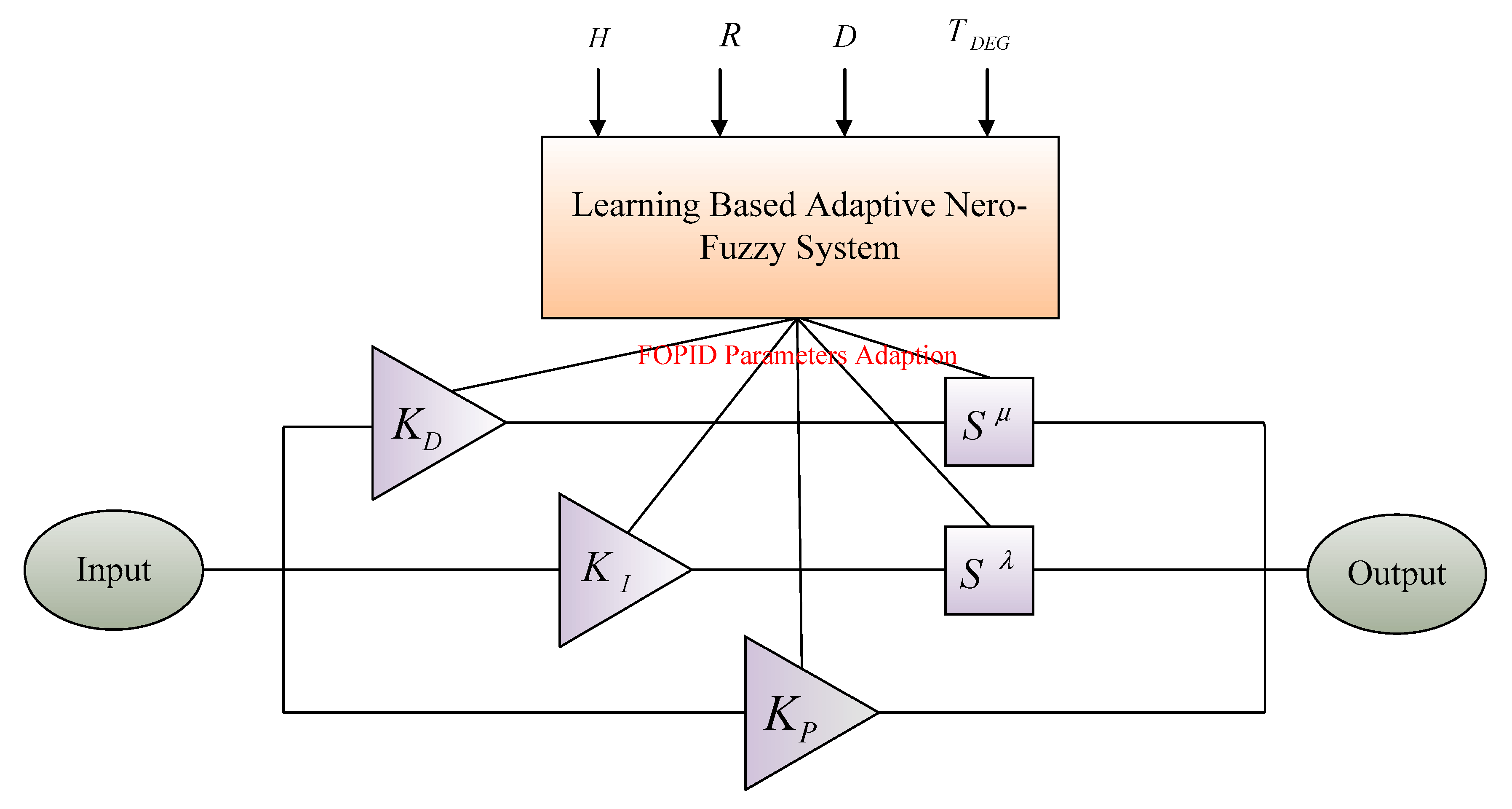
It is important to note that the structure of FOPID is more compatible with a learning-based fuzzy approach which has been described in the following section. Indeed, this proposed control mechanism can include the advantages of the combination of fuzzy logic with PID controller which has been discussed in [26]. In the following, the structure of the proposed controller, which includes some uncertainties like the time constant of the diesel engine generator, the time constant of inertia of the isolated microgrid, the speed droop regulation constant, along with the load damping coefficient, has been shown in Figure 1.
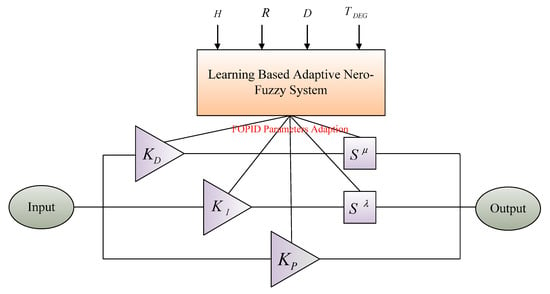
Figure 1.
The structure of the proposed controller.
2.3. Adaption Based on Recurrent Adaptive Neuro-Fuzzy System
The recurrent adaptive neuro-fuzzy system has a responsibility to select parameters of this FOPID controller according to the parametric uncertainties in relation to some important parameters of microgrid. The fuzzy inference of this system is Sugeno definition in which rules can be described as follows:
If is and is , then
If is and is , then
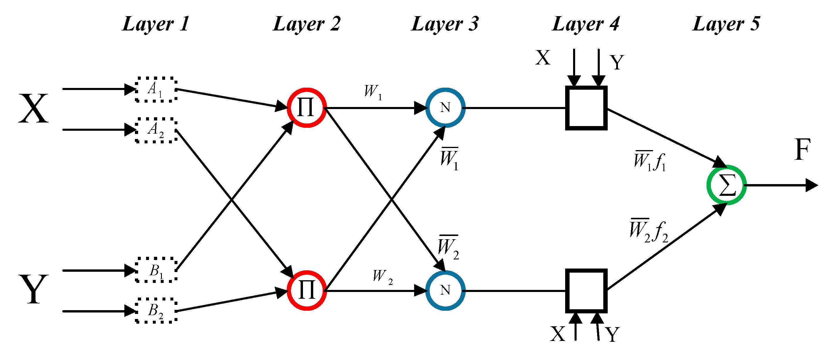
The structure of the above-mentioned system includes several layers in which the outputs are generated from the inputs signals, along with some practical weights. One comprehensive structure including five distinctive layers, which its layers are listed as follows, is illustrated in Figure 2.
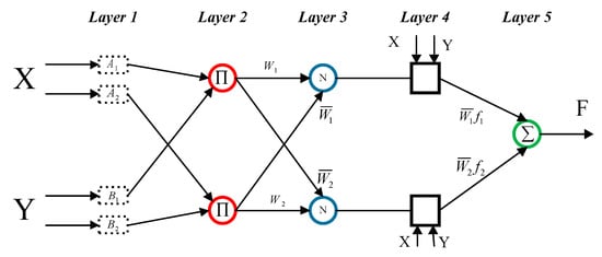
Figure 2.
Architecture of adaptive neuro-fuzzy system.
Layer 1. Layer 1 generates fuzzy value from the input signals. In the fuzzy knowledge, this layer is well known as the fuzzification layer, so that it is able to convert input signals into fuzzy values in a pragmatic way:
is the output of layer, is the membership function, and are incoming signals. and depict the node and layer numbers, respectively.
Layer 2. This layer creates output from the multiplication of incoming fuzzy signals:
Layer 3. The normalization of firing strengths from previous Layer is performed in the nodes of layer3.
is normalized firing strength.
Layer 4. This layer is known as the defuzzification layer.
Layer 5. The overall output is calculated by summing incoming signals in layer5 [27].
In this study, back propagation (BP) algorithm is used to learning and adapting weights of the proposed FOPID controller. At first, weights are randomly chosen in this algorithm. In each step, the output of the network is calculated then the weights be updated based on the difference between the output of the network () and desired output () to minimize the objective function which is presented as follows:
The deviation of weights must be contrary to the deviation of the calculated error to minimize the objective function:
In previous formula, is a constant value in order to update the weight ( that is chosen by users. Additionally, is error of each layer. The equation of updating weights in each step that are generated by utilizing the input signals, error equation, as well as chin rule techniques are presented as follows:
2.4. Fuzzy Logic-Based Controller
In recent years, fuzzy knowledge has received a high level of attention in all different types of industrial setting due to robust performance for some practical applications as well. One of the soft computing tools which have become a focus of attention in the advanced control mechanism in the low-inertia microgrids is fuzzy logic-based controller. This type of soft computing tool is able to yield more satisfactory performance during parametric uncertainties than other traditional controllers. Broadly speaking, fuzzy control mechanisms deploy different types of measurements devices and depend heavily on long-lasting experiences of specialist as well as the knowledge of experts in this field. In fact, new and intelligent fuzzy rule based on professional experiences is a vital aspect of using such controllers in industrial applications. As a result, the complexity of system due to exponential fuzzy rule base can increase considerably and the implementation of this controller can experience a noticeable cost as well. In this paper, in order to compare some soft-computing tools, this fuzzy based controller is introduced and its performance is compared with FOPID which has been trained by RANFIS.
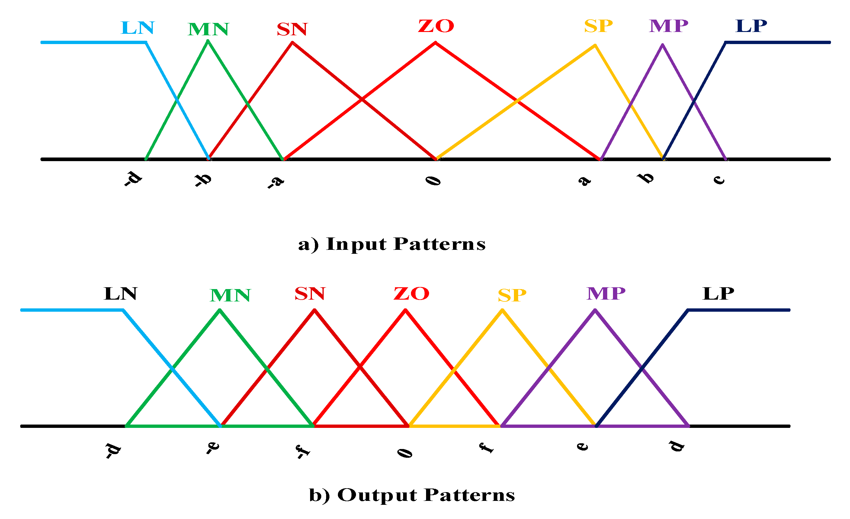
In this fuzzy controller, input signals can be frequency deviation (, along with the rate of change of frequency based on time () and rule based are proposed in Table 1 as well. In addition, the output signal is a standard set point to stimulate the output power of distributed generation to produce more active power during load disturbances as well as several defined uncertainties. This controller heavily is dependent on the membership functions (MFs) which have been shown in Figure symmetrically and tuned by particle swarm optimization (PSO) algorithm.

Table 1.
All fuzzy rules for this proposed fuzzy logic-based controller.
According to Table 1, fuzzy rule can be stated in the form of IF_THEN statements. For example:
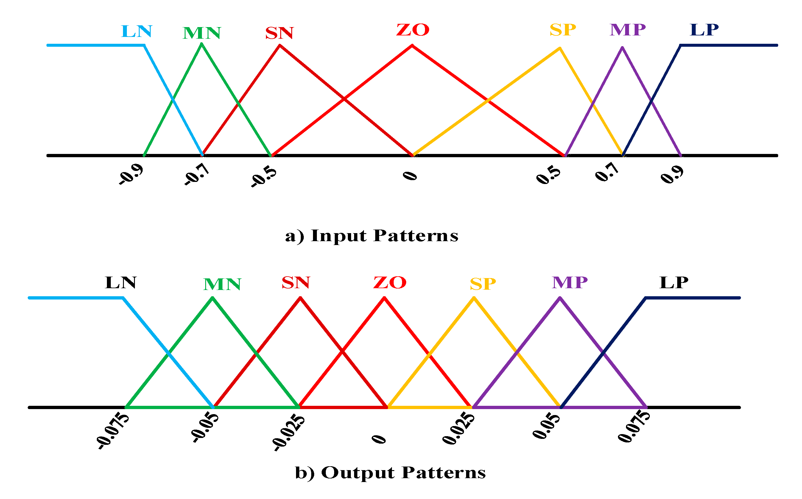
IF is MN and is SN, THEN output will be MP. It is important to say that membership function is called LN (Large negative), MN (medium negative), SN (small negative), ZO (Zero), SP (small positive), MP (medium positive), and LP (large positive), which have been shown in Figure 3 [28].
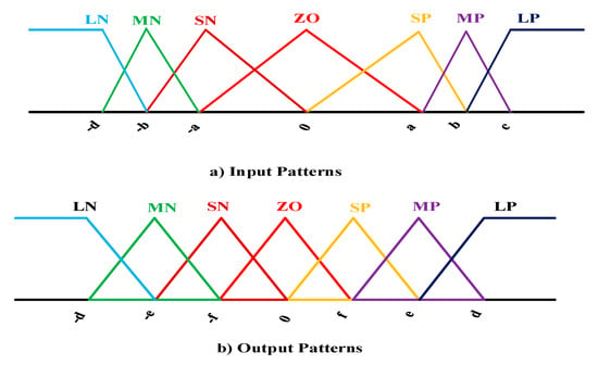
Figure 3.
The pattern of membership function for (a) input signals and (b) output signal.
3. Microgrid Dynamic Model for Frequency Studies
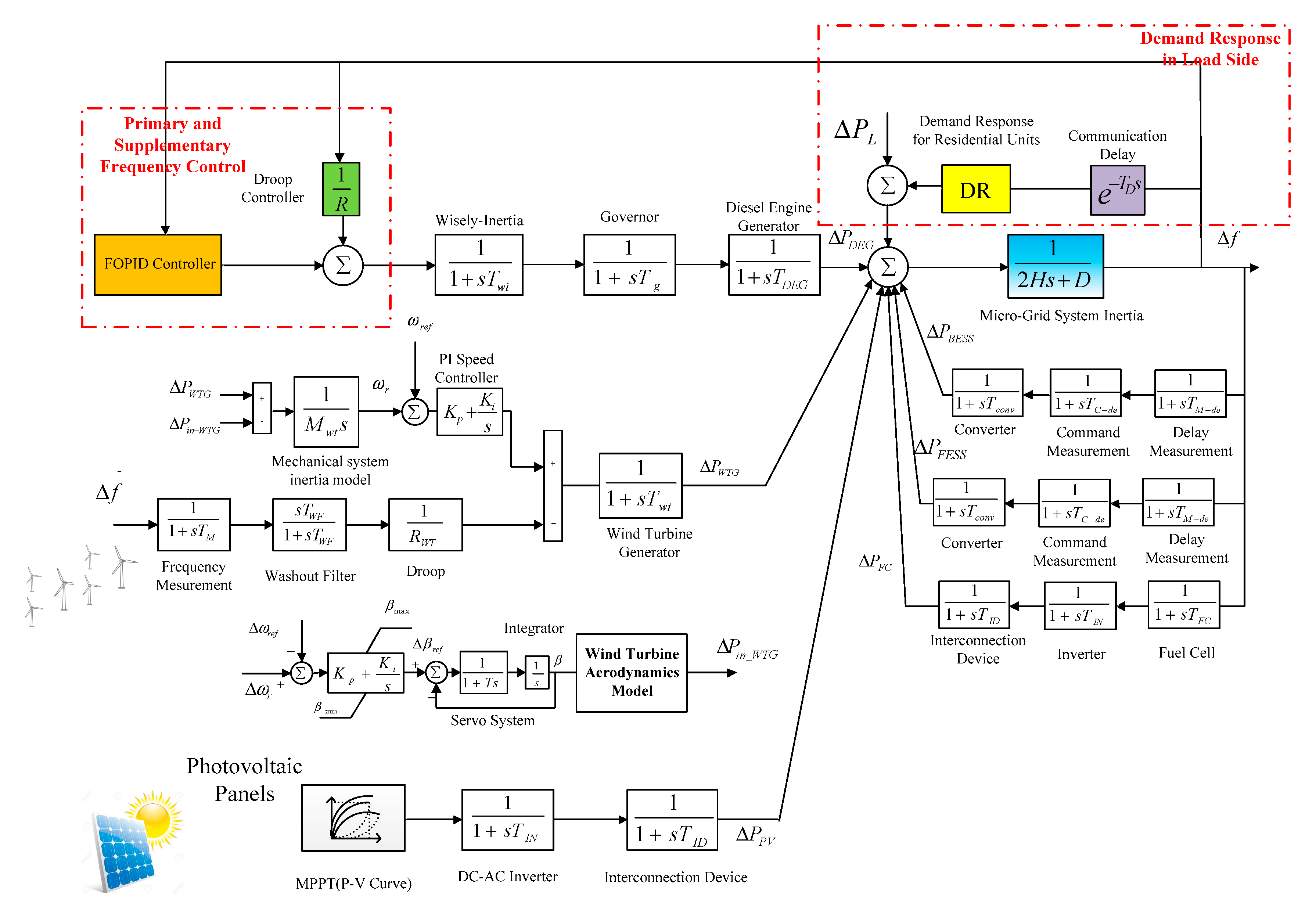
There are different types of dynamic models in the former researches for MGs [29,30]. For instance, in [31,32,33], simplified dynamical models for renewable energy resources as well as energy storage systems (ESSs) have been taken into account as the first-order dynamical frequency models It is important to note that low-order dynamic models may be applicable apparently but they cannot include all dynamic aspects of the frequency behaviour related to parametric uncertainties and climatic patterns including wind power fluctuation and changes in the solar irradiation. Figure 4 shows an MG dynamical frequency model, along with two varied control mechanism including primary and secondary frequency control (LFC) in the generation side as well as demand response program in the load side. In the following step, all relevant parameters of this decarbonized system for a typical MG are represented in Table 2 during different situations [34,35,36].
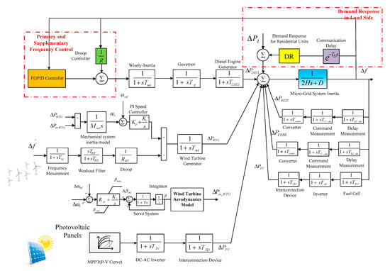
Figure 4.
Dynamic frequency model of the microgrid (MG).

Table 2.
The nominal values of the MG’s parameters. WTG, wind turbine generators; BESS, battery energy storage system; FESS, flywheel energy storage systems.
3.1. Dynamic Model of Wind Turbine Generator
Based on experimental actions as well as previous studies, the output power of the wind turbine generator depends heavily on a non-dimensional coefficient, namely turbine performance coefficient , which is a combination of the tip speed ratio and the blade pitch angle as below [37]:
Tip speed ration can be generally defined by this statement, so that is blade radius, is a symbol of wind speed based on () and is mechanical speed of turbine:
Finally, the maximum output power which is obtained from a wind turbine generator can be given by the following relationship:
In this relationship, wind turbine output power mainly is relation to wind speed (, air density ), surface which are swept by blades of WTG (), and turbine performance coefficient ().
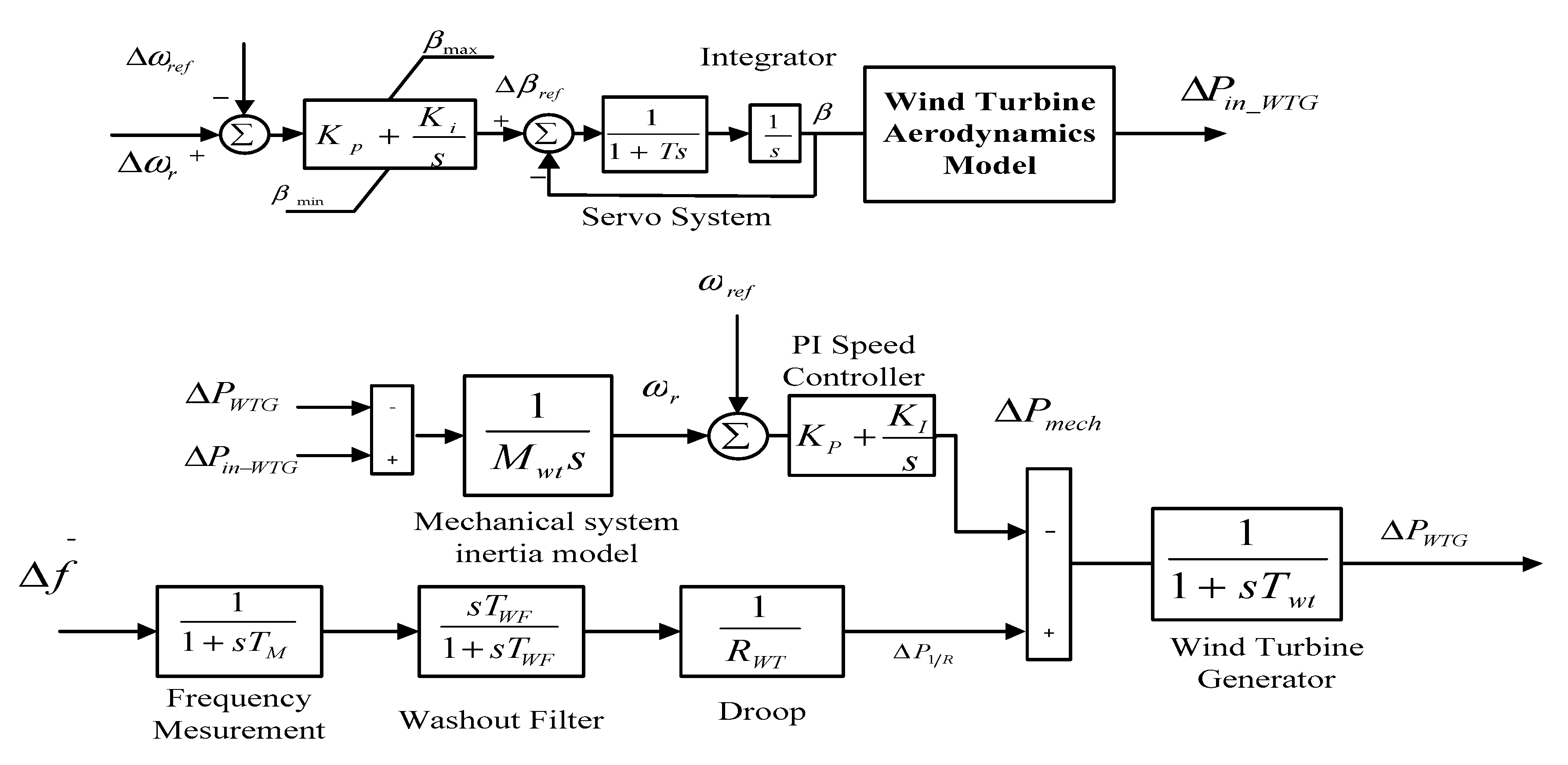
According to the proposed dynamic WTG model, which has been shown in Figure 5, a constant droop which is a symbol of virtual inertia (i.e., hidden inertia) of rotational masses is proposed (). This droop can play an active role in enforcing generation units to inject active power and improve the frequency deviation while some critical events occur. In order to obtain frequency deviation () more precisely, two different device including measurement device and a washout filter which is a high-pass filter are introduced.
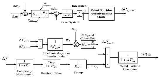
Figure 5.
Layout of wind turbine generator using virtual inertia concept.
One important signal is mechanical power () which compels the rotor speed of WTG to track a desired reference is acquired [38]:
Another signal is the electrical input power of WTG which includes three components including which is a symbol of the wind power changes during blade angle changes, which describes the wind power variation for the small change of angular speed, and is introduced as the power variation for a specific wind speed:
Finally, differences between total active power () and electrical input power () can be presented by taking advantage of rotor swing equation:
In terms of small deviation concept and with regard to , this statement will be obtained:
The Laplace transform of Equation (19) can be given by:
3.2. Dynamic Model of Photovoltaic Panels
The output power of solar panels can be written based on 1 diode and 1 resistance model [39]:
In this model, the amount of current () is related to some component as below:
: Reverse saturation current related to the diode
: Thermal voltage
: A criterion for the deviation of the diode from the Shockley diffusion theory
: Number of series cell in photovoltaic panels
: Series resistor
The photocurrent () depends on the amount of solar radiation during specific day and this photocurrent changes from a time to another time as bellow:
With regard to assumed relationship, characteristic of solar panels can be obtained:
It is important to mention that small signal dynamic model for inverter used in the structure of solar panels is regraded in order to simulate different component of this distributed generation practically. In fact, the output power of solar panels can be obtained based on MPPT curve and transferred through inverter-based topology to the utility grid by deploying an interconnection device, which has been shown in Figure 6 [40].

Figure 6.
Layout of solar panels during different period of time.
3.3. Dynamic Model of Energy Storage Systems (BESS and FESS)
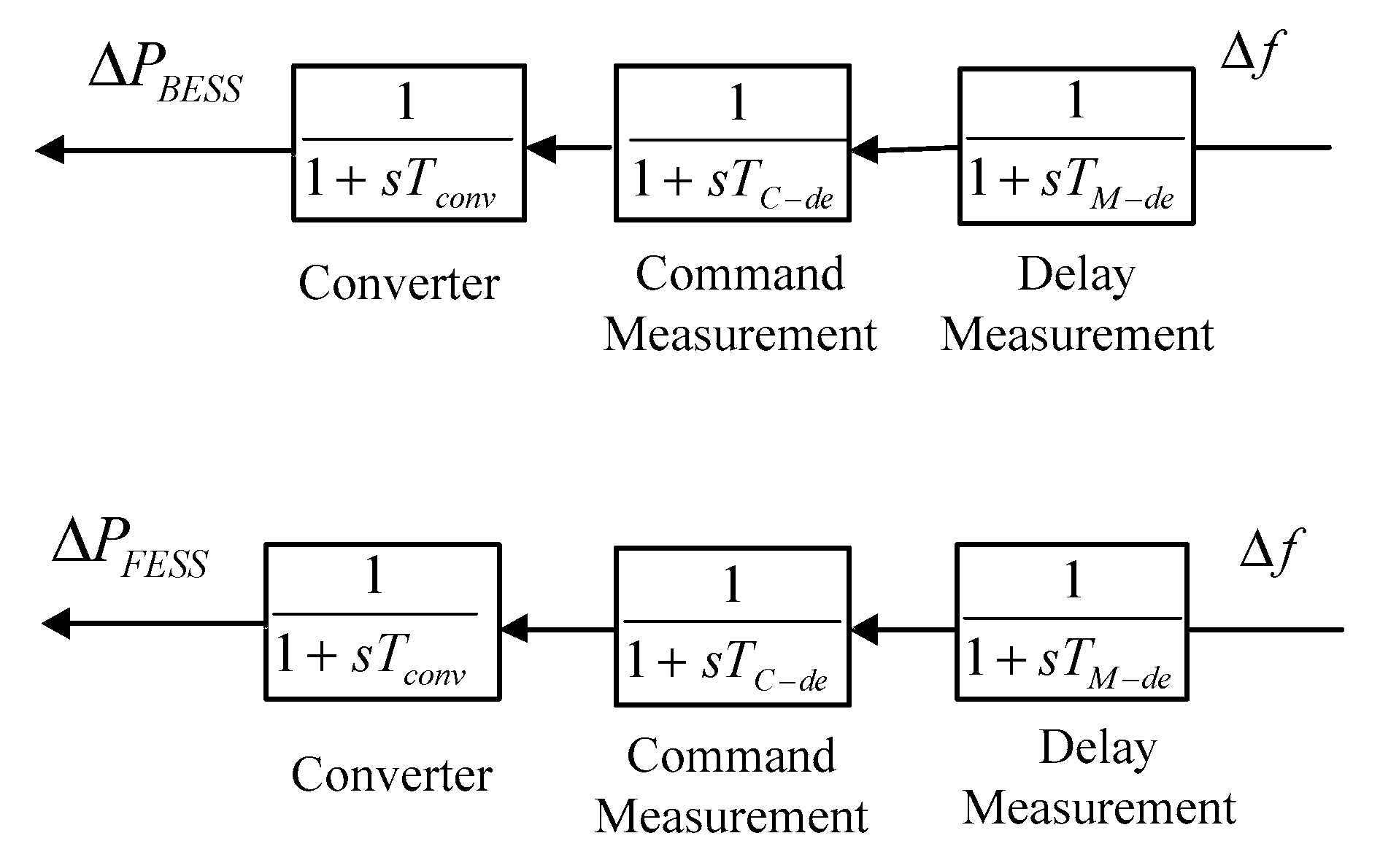
In the layout of microgrids, energy storage systems play an important role in providing sufficient energy for isolated MG within a short period of time in order to protect system stability. It is often argued that it takes a period of time to charge FESS and BESS, and consequently, considering time constants for different components which are used in the structure of energy storage system appears to be necessary [41]. In a great number of previous studies, both BESS and FESS are regarded as the first order models which lead to neglect some dynamic behaviour of ESSs as well. This work expresses the BESS and FESS transfer function as a three-block diagram including frequency measurement device, command delay device as well as converter block in order to consider more accurate dynamic behaviour of ESSs. In fact, for the presented model, is time constant for measurement device, is a symbol for delay of command device and is a time constant for DC to AC converter model according to Figure 7.
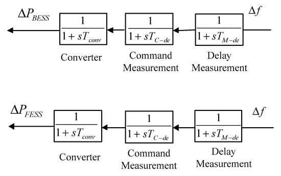
Figure 7.
Layout of dynamic model of BESS and FESS.
3.4. Dynamic Model of Fuel Cell
During frequency studies, the fuel cell is well known as a green energy resource and introduced by three different dynamic blocks including an inverter topology which can be deployed in order to convert DC voltage to AC voltage. Another important block is an interconnection device which links this distributed generation to the power grid in a pragmatic way. Although the fuel cell has a high order characteristic, a three-order structure is adequate for frequency control studies [42]. These three blocks have been illustrated in Figure 8.

Figure 8.
Layout of dynamic model of fuel cell as green energy resource.
3.5. Dynamic Model of Diesel Engine Generator (DEG)
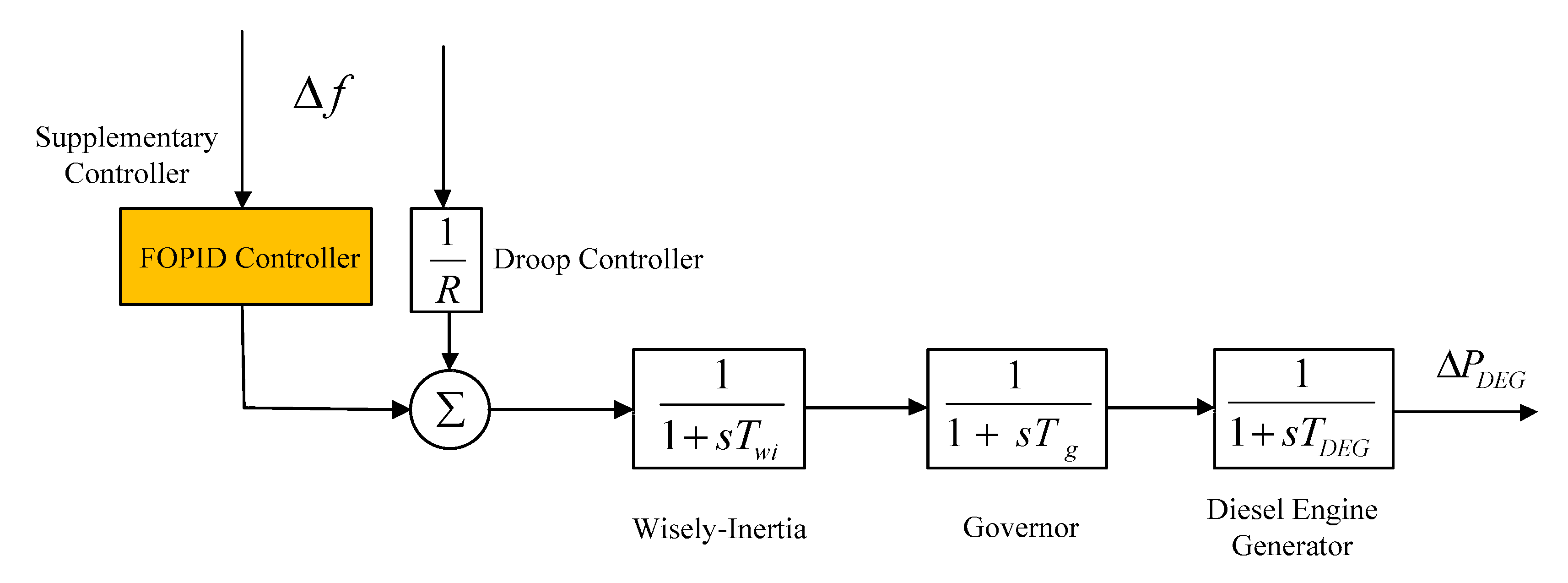
In recent years, taking advantage of diesel engine generator (DEG) has increased considerably for a number of different reasons like high level of reliability, high speed at performance as well as easy implementation in the isolated hybrid microgrids. In order to considering delay communication, one first order block has been proposed in this layout which is called wise delay inertia. In addition, every diesel engine generator consists of a turbine, governor and wise delay inertia, which are illustrated through typical transfer functions as well. In this dynamic model, which has been depicted in Figure 9, shows the amount of frequency deviation, is time constant relate to governor, is time constant associated with diesel engine generator as well as and is regarded as wise delay time constant respectively. In the following, depicts speed regulation coefficient of the DEG. In this proposed AC microgrid, DEG, which is located in the generation side, take responsibility for mitigate frequency devotion as soon as possible to prevent any collapse when some disturbances enter during operation of microgrid. The state-of-the-art control mechanism, namely FOPID is proposed in order to alleviate frequency excursion and reach the nominal value of frequency system in this paper. It is important to mention that this distributed generation is generally regarded as fast power injection in the isolated hybrid microgrids [43].
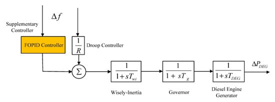
Figure 9.
Layout of diesel engine generator as fast active power injection source.
4. Simulation Results and Discussion
In this study, a hybrid microgrid, which comprises dynamic models of diesel engine generator, energy storage systems (ESSs), photovoltaic panel, and wind turbine generator, is deployed to scrutinize the effectiveness of the proposed method including a DR program in the load side as well as load frequency control (LFC) scheme in the generation side. At the first stage, an intelligent strategy for frequency regulation which consists of two control mechanism including primary and secondary frequency control is proposed. During this plan, an adaptive learning method, which is based on fuzzy knowledge, is submitted in the generation side during parametric uncertainties. Afterwards, a frequency-based demand response (DR) program, along with an objective function, is applied into decentralized residential houses in order to decrease the level of rate of consumptions. In order to evaluate the performance of the both suggested methods, three different case studies are defined as follows:
- Case 1: Microgrid during load disturbances and weather changes without any uncertainty
- Case 2: Microgrid in the presence of parametric uncertainties
- Case 3: Demand response Program method in the load side, along with optimal frequency controller
Case 1
The first case is presented to assess the efficiency of fractional order PID for the above-mentioned hybrid microgrid in the presence of the nominal parameters in Table 2. In order to design parameters of FOPID controller in a sensible way, the Nelder–Mead optimization algorithm is deployed in order to minimize the integral square error of the frequency response of the low-inertia system which is given by the following Equation [44]:
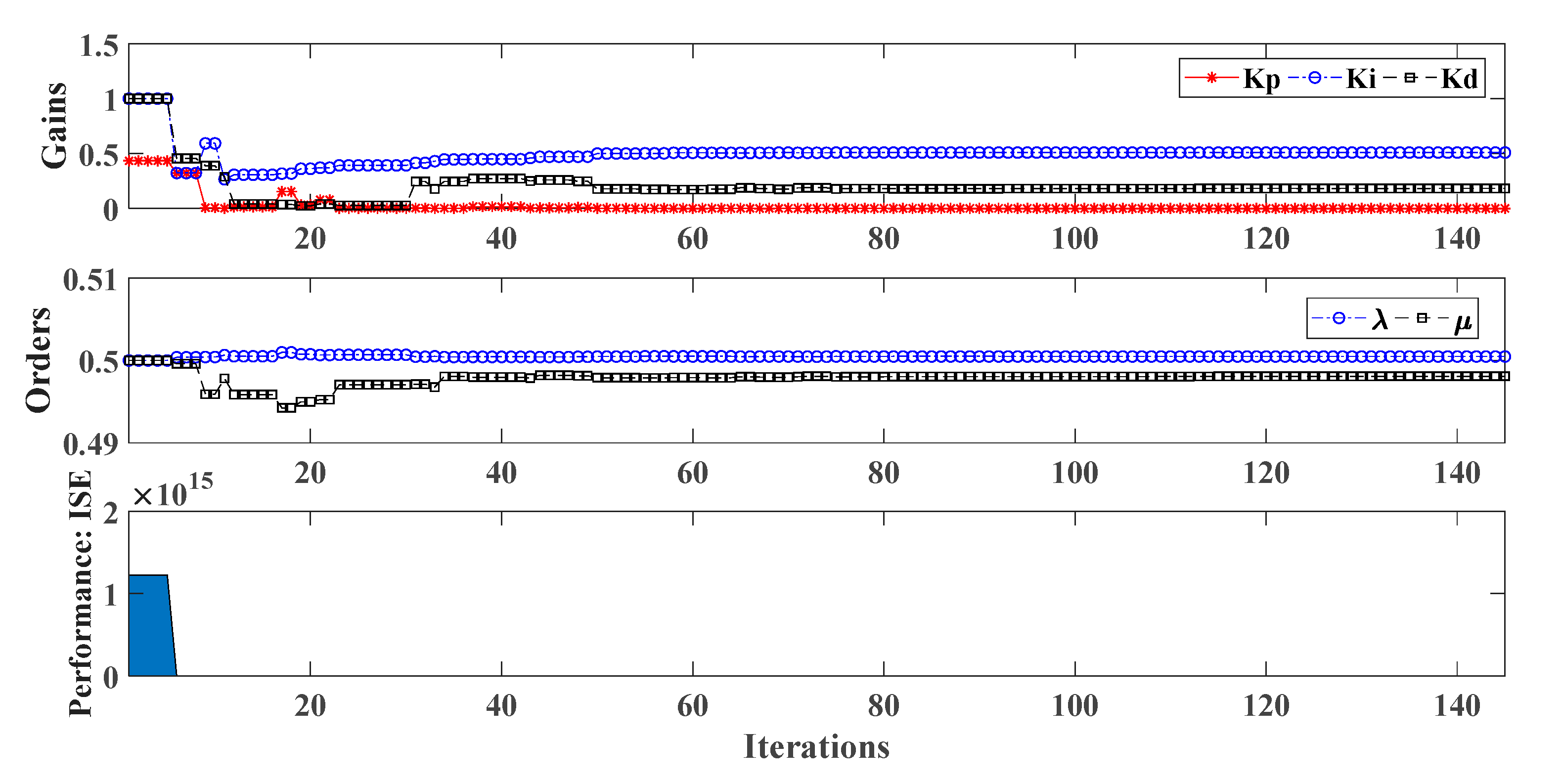
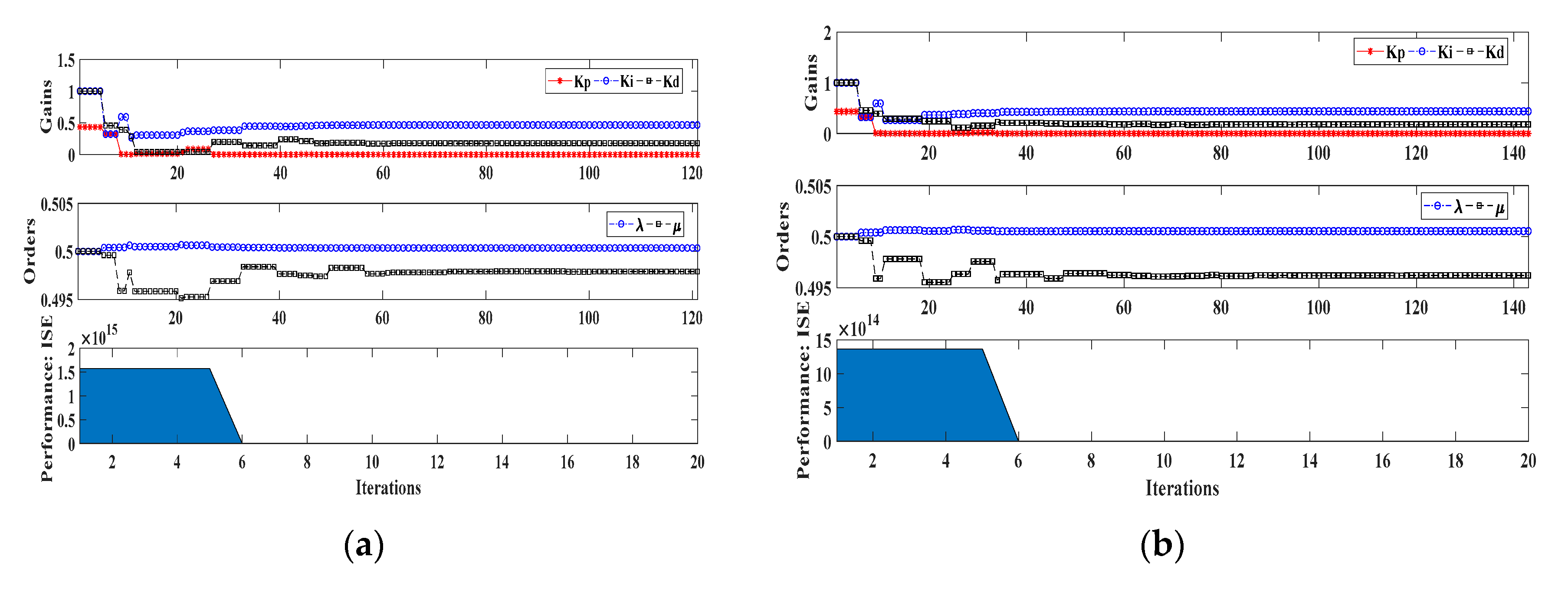
The parameters of designed FOPID controller are integral, derivative and proportional constant, along with the metrics of this controller which are depicted in Table 3. In addition, an ongoing trend related to the selection of these parameters as well as metrics of this controller has been illustrated in Figure 10. In the following, in order to compare the performance of proposed controller in the generation side, an optimal traditional PID has been introduced as well.

Table 3.
The parameters of the designed fractional-order proportional-integral-derivative (FOPID) and optimal PID.
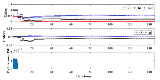
Figure 10.
Metrics and parameters of FOPID.
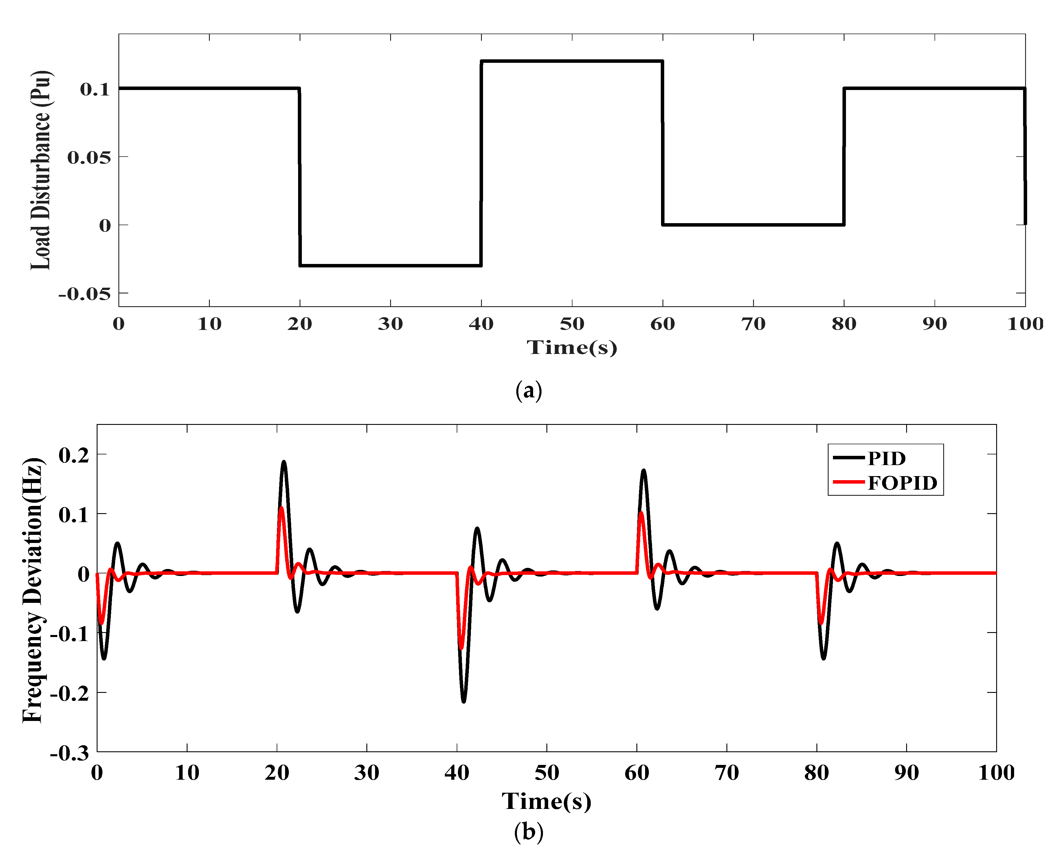
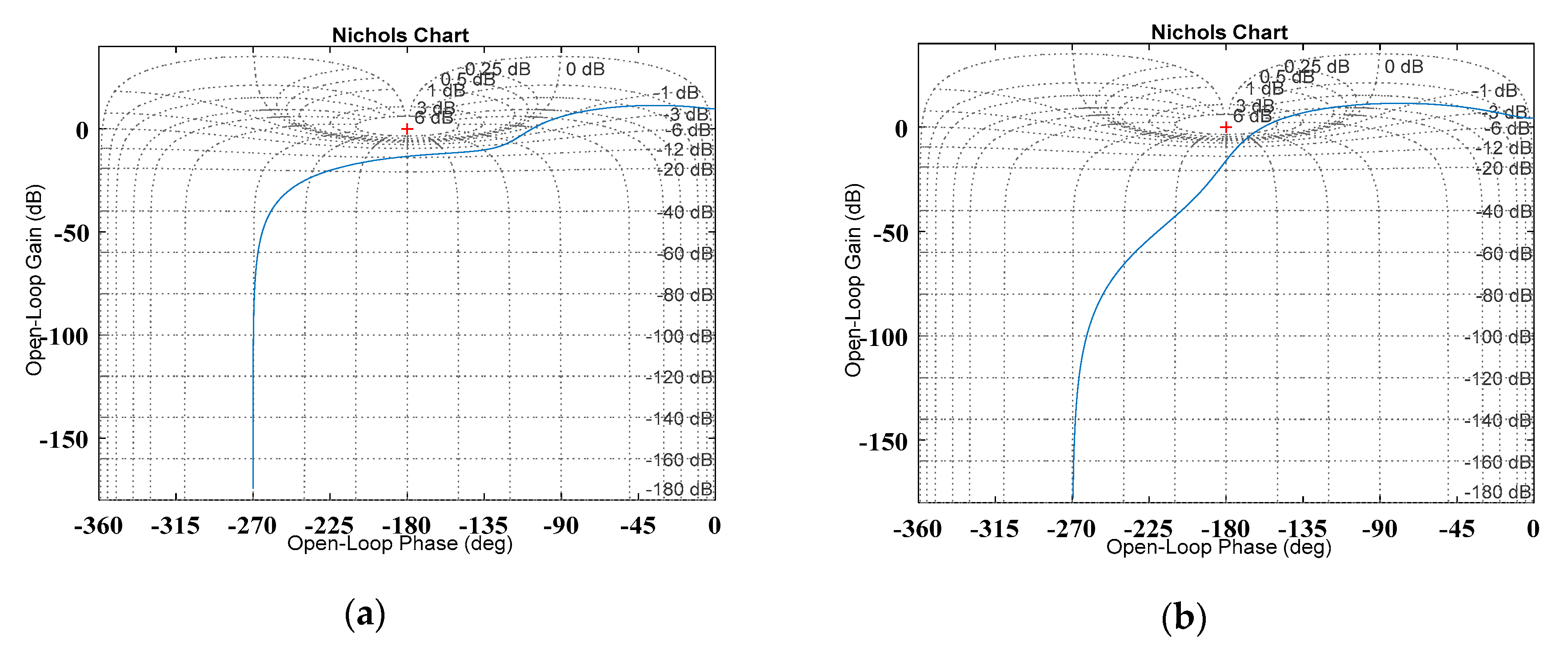
The results of frequency deviation, when a multiple load step based on Figure 11a is applied into microgrid for both controllers, are shown in Figure 11b. As shown in this figure, the frequency deviation curve varies considerably while the PID controller is used in the first scenario. As can be observed, the PID controller damps the oscillation within roughly 10 s time period effectively. However, the proposed FOPID controller alleviates oscillating frequency behaviors faster. In addition, the frequency deviation nadir point on the condition of the FOPID controller implementation is lower than nadir point during application of PID controller. It is obvious that FOPID yields more satisfactory performance than PID controller in terms of performance during load disturbances and stability analyze based on obtained results in Table 3 and Figure 11b. In fact, the phase margin as well as gain margin of this designed FOPID is more robust than PID one based on obtained results and Nichols chart which is illustrated in Figure 12.
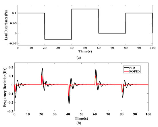
Figure 11.
(a) Load step pattern; (b) frequency deviation of low-inertia microgrid (case 1).
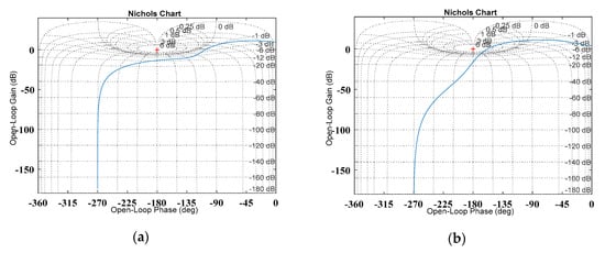
Figure 12.
Nichols chart for (a) open loop of FOPID, and (b) open loop of PID.
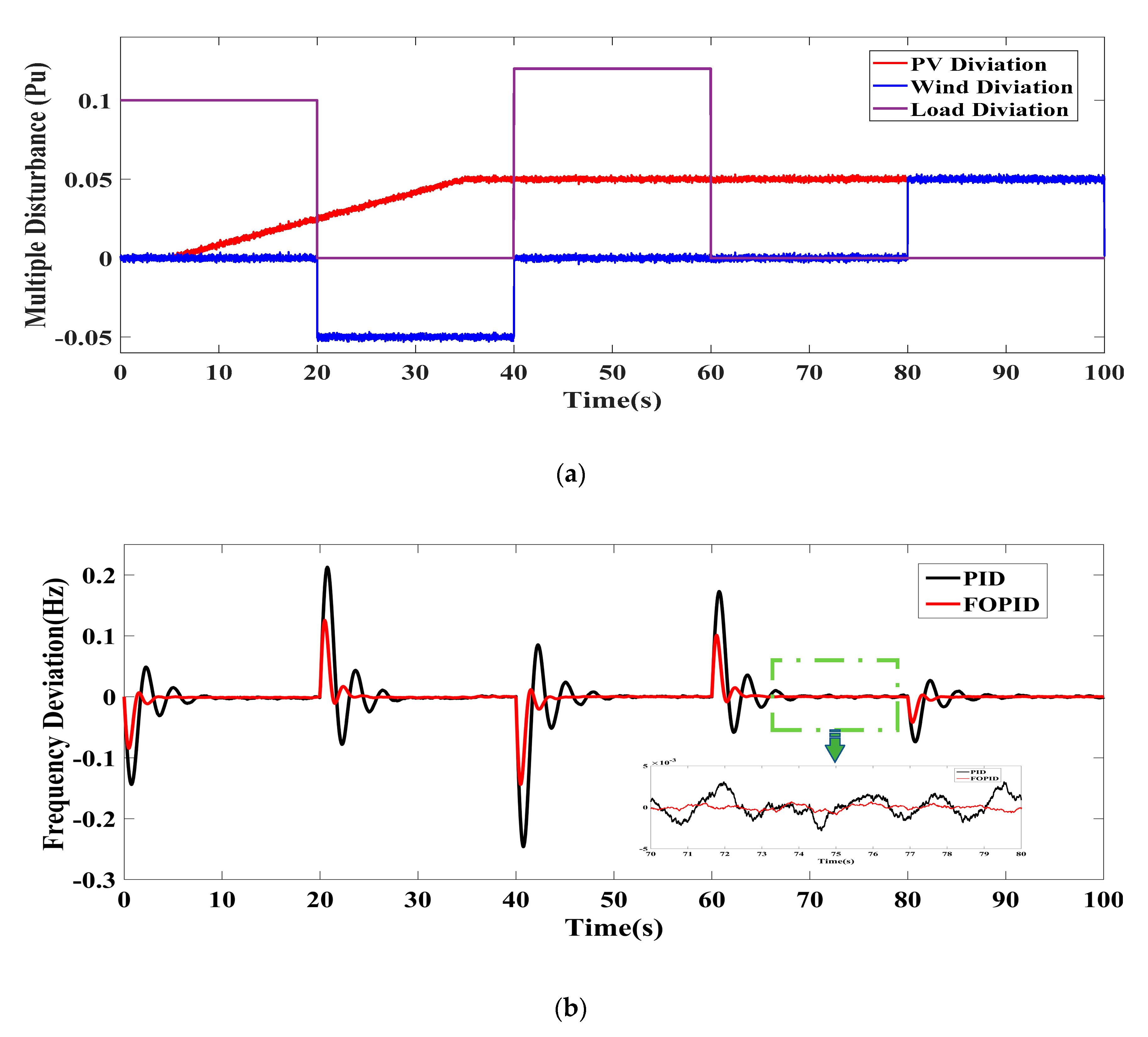
In addition to step load disturbance, changes in climatic patterns can have detrimental effects on the frequency response due to existing inverter-based structures in a hybrid microgrid and lack of rotational masses in distributed energy resources as well. In the following, a pattern of fluctuation in wind speed, sun irradiation as well as load disturbances is shown in Figure 13a and the performance of both mentioned controllers are evaluated in more details in Figure 13b. It is obvious that the proposed FOPID controller has better performance than PID in terms of mitigation of the disturbance owing to some unwanted fluctuations.
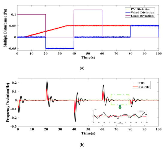
Figure 13.
(a) Pattern of multiple disturbance; (b) frequency response in the presence of multiple disturbances.
Case 2
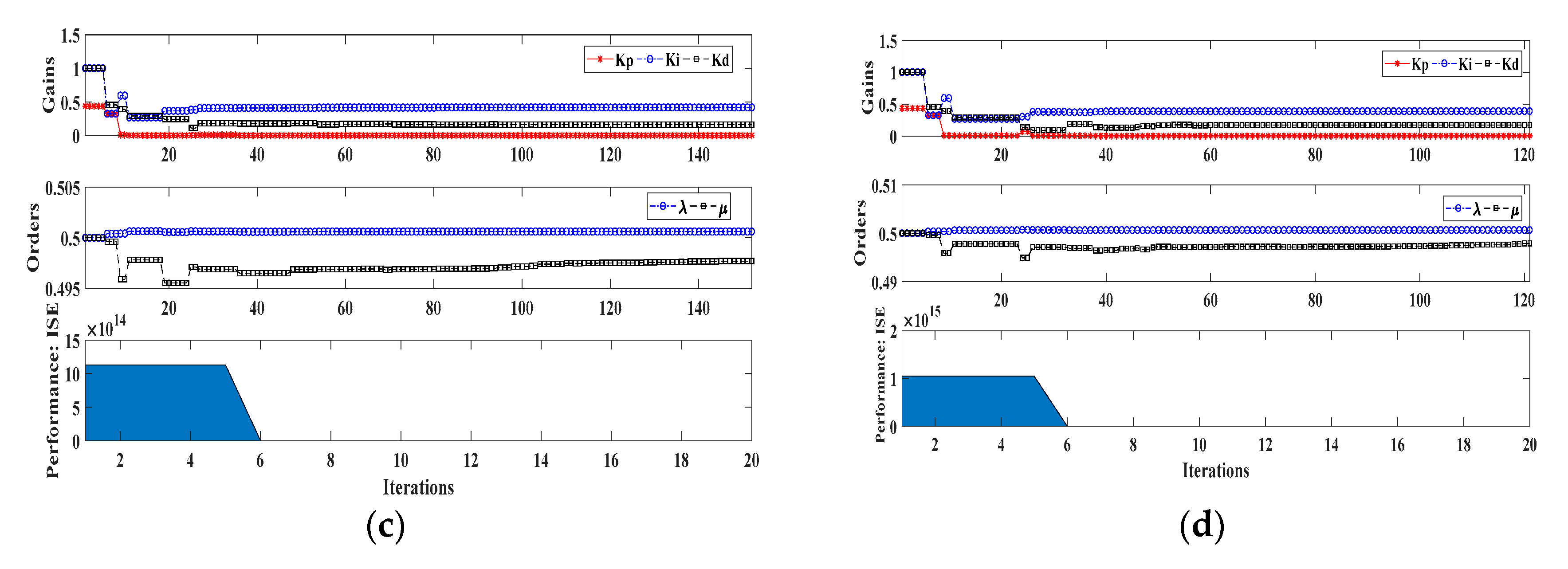
In recent years, a great number of isolated microgrids have experienced new challenges in relation to the resiliency and stability due to parametric uncertainties. Advanced combination methods of optimization tools and learning methods haves brought some benefits to different types of topologies in the power systems. As a result, to overcome this challenge related to isolated microgrid which is separated form utility grid practically, the proposed FOPID is tuned by a learning-based neuro-fuzzy system during some uncertainties associated with the time constant of the diesel engine generator (), the time constant of inertia of the isolated microgrid (), the speed droop regulation constant (), along with the load damping coefficient () can be a proper solution. The range of uncertainties and learning patterns are given in Table 4 and Table 5, respectively and the optimized parameters and metrics of each pattern are depicted in Figure 14. It is evident that the metric has high value at the primary iteration and after 6 iterations, the metrics achieve near zero and parameters of this controller converge on their final values.

Table 4.
Patterns in relation to the learning process of FOPID controller.

Table 5.
The parameters of the designed FOPID.
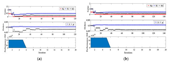
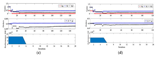
Figure 14.
(a) Metrics of pattern 2; (b) metrics of pattern 3; (c) metrics of pattern 4; (d) metrics of pattern 5.
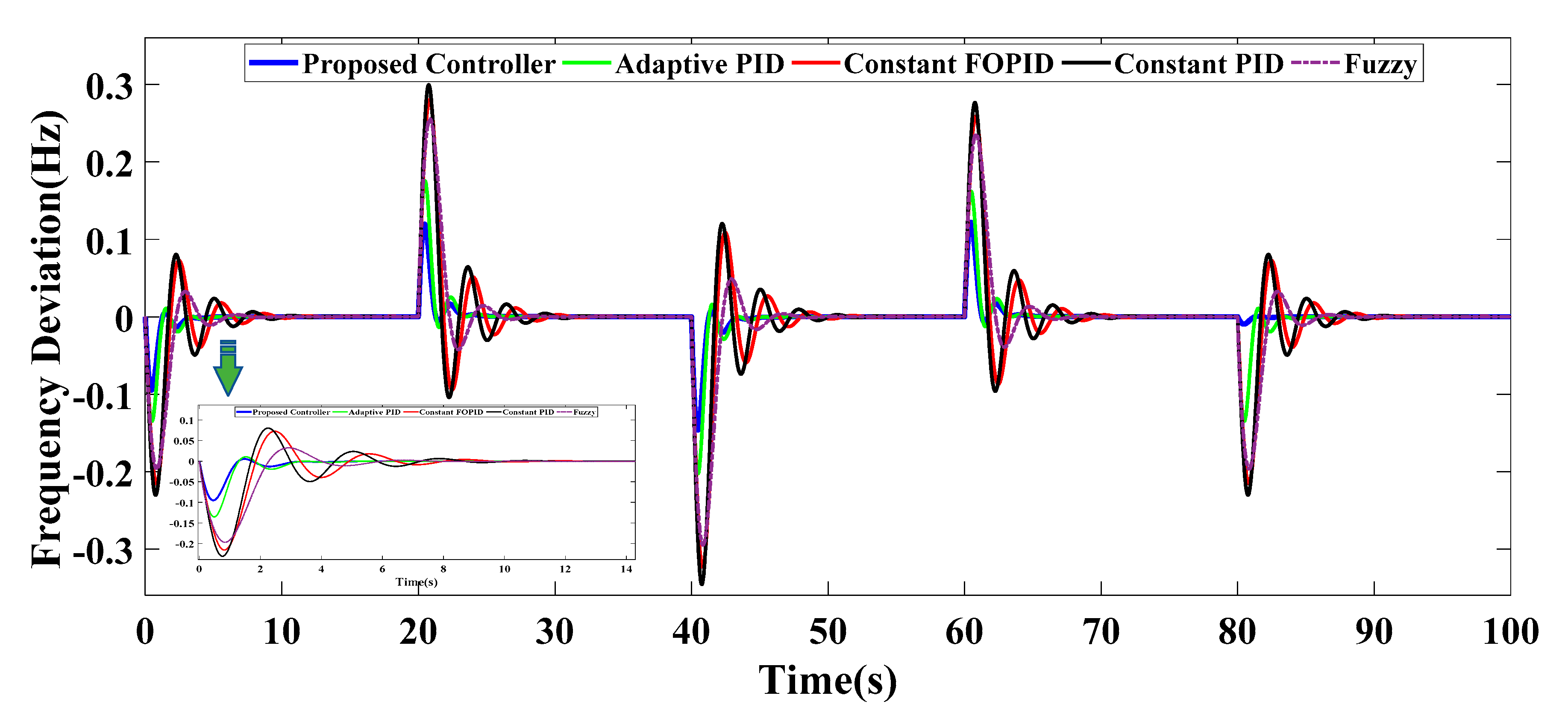
In order to illustrate the performance of this learning method, the parameters as well as metric of FOPID controller can be adjusted by the learning-based neuro-fuzzy system for the various values of microgrid’s parameters. In the following, another soft-computing tool, namely a fuzzy-logic based controller which their membership functions have been selected by PSO algorithm, is introduced and applied into the system to minimize the integral square errors () during parameters uncertainties. Behavior of the all controllers is shown and compared with each other in Figure 15 with regard to certain parametric uncertainty including ,,, and , recpectively. This figure depicts that the frequency excursion of this isolated system can improve considerably by the use of the proposed FOPID controller in terms of settling time, frequency nadir point, rising time as well as undershoot. In fact, trained PID and FOPID yields more acceptable performance compared to these controllers without any learning process. A comprehensive comparison between different types of control mechanisms, when a 0.1 p.u load disturbance is only regarded, has been made in Table 6 by deploying other different criteria such as integral absolute error () as well as integral time absolute error () as follows:
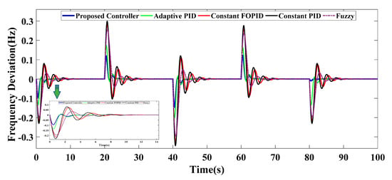
Figure 15.
Frequency deviation of hybrid microgrid different type of traditional and modern frequency controller (PID, Fuzzy, and FOPID) (Case 2).

Table 6.
Comparison between different type of traditional and modern frequency controller (0.1 p.u load disturbance).
In addition, the patterns of input and output signals of this soft-computing fuzzy logic controller have been depicted in Figure 16.
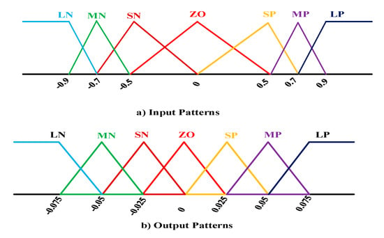
Figure 16.
Membership function patterns obtained by optimization tool (particle swarm optimization) for (a) input signals, and (b) output signals.
Case 3
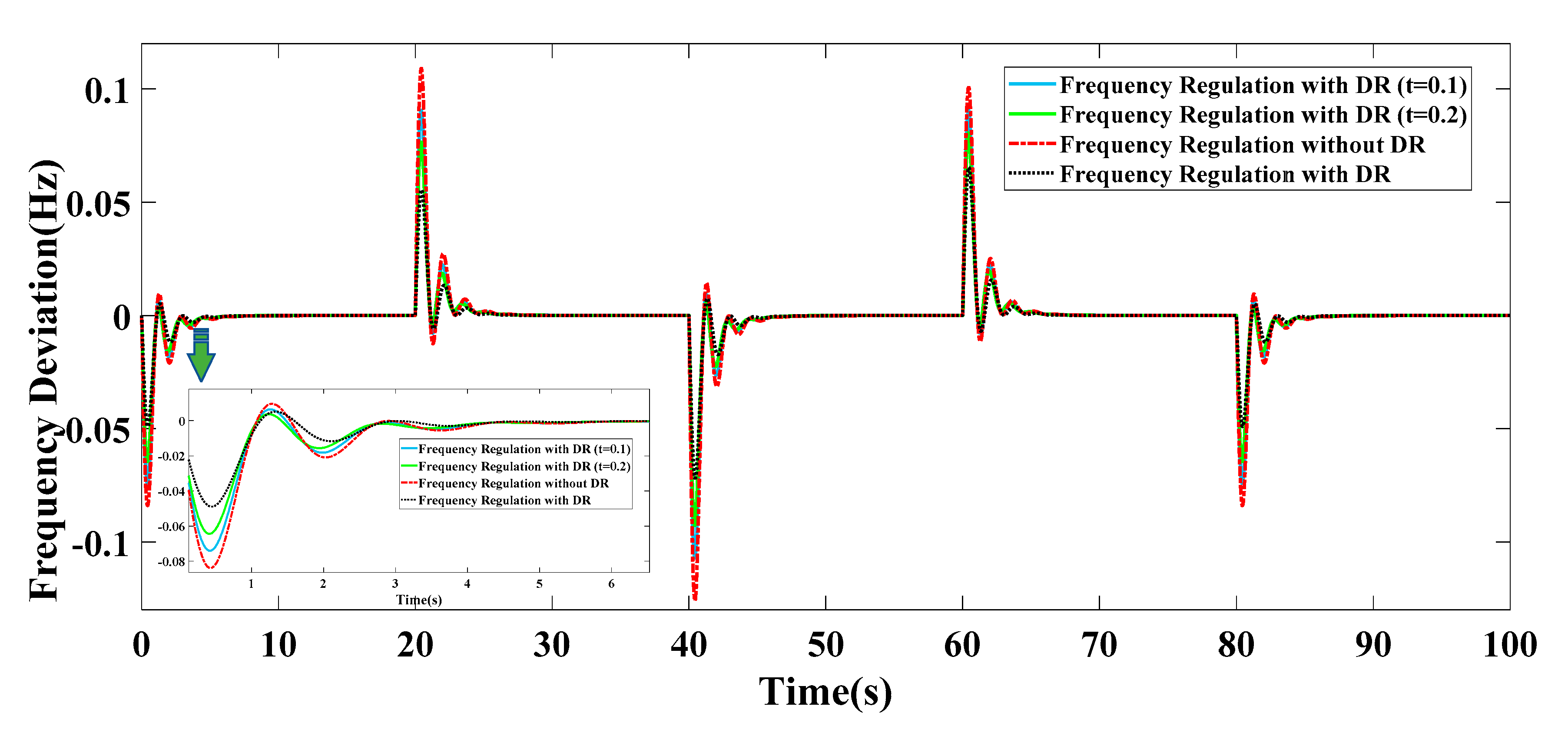
In the last scenario, the suggested demand response program, which includes communication time delay as well as a predetermined scheduling, is used for this hybrid microgrid to alleviate the frequency deviation. It is important to mention that this approach is deployed during the load side by taking advantage of controllable appliances and energy storage systems, while the best solution in the second case, adaptive FOPID controller was carried out during the generation side by learning method. In this case, the consumption rate of controllable appliances and the charge and discharge process of BESSs and PHEVs are regulated based on a critical issue, namely the frequency response of the system. During this section, 20% of whole daily consumptions are regarded as controllable consumptions which consist of dishwasher, cloth dryer, dishwasher, and locally battery systems consumptions. In order to consider the delay of the control mechanism, a delay block has been regarded and the behavior of the proposed approach is also indicated when there is a communication delay between the load side and the generation side. According to Figure 17, the proposed demand response program greatly helps to reduce the frequency deviation even with considering time delay between two sides. In addition, a comparison between different methods, when a 0.1 p.u load disturbance is only applied, has been made in Table 7. This comparison includes three different criteria such as and along with some characteristic related to frequency response (rising time, settling time and undershoot). In fact, the use of this optimum demand response program in the load side leads settling time to decrease considerably, so that it affects the generation costing and operating expenditure to a great extent.
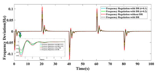
Figure 17.
Frequency deviation of low-inertia hybrid microgrid during different load side management with regard to delay communication (Case 3).

Table 7.
Comparison between different load side management during delay communication (0.1 p.u load disturbance).
5. Conclusions
In recent years, the tendency towards using the stand-alone hybrid microgrid owing to unparalleled capabilities to provide secure electricity has increased considerably. All microgrids on the islanded mode may face an intricate challenge due to separation of the utility grid which is called the low-inertia systems. This concept makes it difficult to regulate the frequency excursion effectively during some parametric uncertainties. In contrast to previous researches, this paper takes advantage of two methods which is intelligent combination of a learning-based FOPID controller and a demand side management (DSM) program for a hybrid MG including different types of distributed generations (DGs). To investigate the effectiveness of this combination, the simulation results are shown during three varied case studies. The first and second case studies indicate that the learning-based control approach is able to alleviate frequency excursion greatly in terms of settling time, rising time, undershoot, and nadir frequency response during operational conditions compared to the traditional methods. Furthermore, the last case reveals that the assumed demand load management, along with a proposed communication delays between the load side and the generation side can improve the frequency deviation practically.
Author Contributions
Conceptualization, M.B. and A.A.; methodology, M.B. and A.A.; software, M.B.; validation, M.B., A.A. and S.M.M.; formal analysis, M.B. and A.A.; investigation, M.B. and A.A.; resources, M.B. and A.A.; data curation, M.B. and A.A.; writing—original draft preparation, M.B. and A.A.; writing—review and editing, M.B., A.A. and S.M.M.; supervision, S.M.M.; project administration, S.M.M. All authors have read and agreed to the published version of the manuscript.
Funding
This research received no external funding.
Conflicts of Interest
The authors declare no conflict of interest.
Nomenclature
| Total consumption | |
| Uncontrollable appliances consumption | |
| Binary switch of controllable appliances | |
| Energy storage systems state of charge | |
| Charged power | |
| Discharged power | |
| Energy storage systems charge binary switch | |
| Energy storage systems discharge binary switch | |
| Discharge binary variable of batteries hour | |
| Charge binary variable of batteries | |
| Discharge binary variable of PHEV | |
| Charge binary variable of PHEV | |
| Charged power of battery | |
| Charged power of PHEV | |
| Discharged power of battery | |
| Discharged power of PHEV | |
| Controllable appliances power consumption | |
| The amount time of appliances used in a day or a particular period of a day | |
| Lower band of the appliances available time | |
| Upper band of the appliances available time | |
| Primary SOC | |
| Initial SOC | |
| Maximum value of SOC | |
| Minimum value of SOC | |
| Lower band of charged power | |
| Upper band of charged power | |
| Lower band of discharged power | |
| Upper band of discharged power | |
| Charge coefficients | |
| Discharge coefficients | |
| Batteries charge coefficients | |
| Batteries discharge coefficients | |
| PHEV charge coefficients | |
| PHEV discharge coefficients | |
| Operator order of FOPID | |
| Limits of the operation Limits of the operation | |
| Number of steps | |
| Step size | |
| m | First integer larger than |
| X, Y | Inputs of neuro-fuzzy network |
| O | Output of each layer |
| Fuzzy value of inputs | |
| W | weights of network |
| Error of layer |
References
- Martínez-Álvarez, F.; Schmutz, A.; Asencio-Cortés, G.; Jacques, J. A Novel Hybrid Algorithm to Forecast Functional Time Series Based on Pattern Sequence Similarity with Application to Electricity Demand. Energies 2019, 12, 94. [Google Scholar] [CrossRef]
- Faraji, J.; Babaei, M.; Bayati, N.; A Hejazi, M. A Comparative Study between Traditional Backup Generator Systems and Renewable Energy Based Microgrids for Power Resilience Enhancement of a Local Clinic. Electronics 2019, 8, 1485. [Google Scholar] [CrossRef]
- Dong, X.; Zhang, X.; Jiang, T. Adaptive Consensus Algorithm for Distributed Heat-Electricity Energy Management of an Islanded Microgrid. Energies 2018, 11, 2236. [Google Scholar] [CrossRef]
- Hossain, M.J.; Pota, H.R.; Mahmud, M.A.; Aldeen, M. Robust control for power sharing in microgrids with low-inertia wind and PV generators. IEEE Trans. Sustain. Energy 2014, 6, 1067–1077. [Google Scholar] [CrossRef]
- Dhillon, S.S.; Lather, J.S.; Marwaha, S. Multi objective load frequency control using hybrid bacterial foraging and particle swarm optimized PI controller. Int. J. Electr. Power Energy Syst. 2016, 79, 196–209. [Google Scholar] [CrossRef]
- Ghafouri, A.; Milimonfared, J.; Gharehpetian, G.B. Fuzzy-adaptive frequency control of power system including microgrids, wind farms, and conventional power plants. IEEE Syst. J. 2017, 12, 2772–2781. [Google Scholar] [CrossRef]
- Abazari, A.; Monsef, H.; Wu, B. Load frequency control by de-loaded wind farm using the optimal fuzzy-based PID droop controller. IET Renew. Power Gener. 2018, 13, 180–190. [Google Scholar] [CrossRef]
- Ersdal, A.M.; Imsland, L.; Uhlen, K. Model predictive load-frequency control. IEEE Trans. Power Syst. 2015, 31, 777–785. [Google Scholar] [CrossRef]
- Gholamrezaie, V.; Dozein, M.G.; Monsef, H.; Wu, B. An optimal frequency control method through a dynamic load frequency control (LFC) model incorporating wind farm. IEEE Syst. J. 2017, 12, 392–401. [Google Scholar] [CrossRef]
- Abazari, A.; Dozein, M.G.; Monsef, H. An optimal fuzzy-logic based frequency control strategy in a high wind penetrated power system. J. Frankl. Inst. 2018, 355, 6262–6285. [Google Scholar]
- Zeng, G.-Q.; Xie, X.-Q.; Chen, M.-R. An adaptive model predictive load frequency control method for multi-area interconnected power systems with photovoltaic generations. Energies 2017, 10, 1840. [Google Scholar] [CrossRef]
- Abazari, A.; Monsef, H.; Wu, B. Coordination strategies of distributed energy resources including FESS, DEG, FC and WTG in load frequency control (LFC) scheme of hybrid isolated micro-grid. Int. J. Electr. Power Energy Syst. 2019, 109, 535–547. [Google Scholar] [CrossRef]
- Eshetu, W.; Sharma, P.; Sharma, C. ANFIS based load frequency control in an isolated micro grid. In Proceedings of the 2018 IEEE International Conference on Industrial Technology (ICIT), Lyon, France, 20–22 February 2018; pp. 1165–1170. [Google Scholar]
- Wang, H.; Zeng, G.; Dai, Y.; Bi, D.; Sun, J.; Xie, X. Design of a fractional order frequency PID controller for an islanded microgrid: A multi-objective extremal optimization method. Energies 2017, 10, 1502. [Google Scholar] [CrossRef]
- Latif, A.; Das, D.C.; Barik, A.K.; Ranjan, S. Maiden coordinated load frequency control strategy for ST-AWEC-GEC-BDDG-based independent three-area interconnected microgrid system with the combined effect of diverse energy storage and DC link using BOA-optimised PFOID controller. IET Renew. Power Gener. 2019, 13, 2634–2646. [Google Scholar] [CrossRef]
- Latif, A.; Das, D.C.; Ranjan, S.; Barik, A.K. Comparative performance evaluation of WCA-optimised non-integer controller employed with WPG–DSPG–PHEV based isolated two-area interconnected microgrid system. IET Renew. Power Gener. 2019, 13, 725–736. [Google Scholar] [CrossRef]
- Mukherjee, V. Day-ahead demand side management using symbiotic organisms search algorithm. IET Gener. Transm. Distrib. 2018, 12, 3487–3494. [Google Scholar]
- Bahrami, S.; Amini, M.H.; Shafie-Khah, M.; Catalao, J.P.S. A decentralized renewable generation management and demand response in power distribution networks. IEEE Trans. Sustain. Energy 2018, 9, 1783–1797. [Google Scholar] [CrossRef]
- Wang, H.; Wang, S.; Tang, R. Development of grid-responsive buildings: Opportunities, challenges, capabilities and applications of HVAC systems in non-residential buildings in providing ancillary services by fast demand responses to smart grids. Appl. Energy 2019, 250, 697–712. [Google Scholar] [CrossRef]
- Amini, M.H.; Moghaddam, M.P.; Karabasoglu, O. Simultaneous allocation of electric vehicles’ parking lots and distributed renewable resources in smart power distribution networks. Sustain. Cities Soc. 2017, 28, 332–342. [Google Scholar] [CrossRef]
- Munkhammar, J.; Widén, J.; Rydén, J. On a probability distribution model combining household power consumption, electric vehicle home-charging and photovoltaic power production. Appl. Energy 2015, 142, 135–143. [Google Scholar] [CrossRef]
- Galus, M.D.; Koch, S.; Andersson, G. Provision of load frequency control by PHEVs, controllable loads, and a cogeneration unit. IEEE Trans. Ind. Electron. 2011, 58, 4568–4582. [Google Scholar] [CrossRef]
- Benysek, G.; Bojarski, J.; Smolenski, R.; Jarnut, M.; Werminski, S. Application of stochastic decentralized active demand response (DADR) system for load frequency control. IEEE Trans. Smart Grid 2016, 9, 1055–1062. [Google Scholar] [CrossRef]
- Rastegar, M.; Fotuhi-Firuzabad, M.; Zareipour, H. Home energy management incorporating operational priority of appliances. Int. J. Electr. Power Energy Syst. 2016, 74, 286–292. [Google Scholar] [CrossRef]
- Padula, F.; Visioli, A. Tuning rules for optimal PID and fractional-order PID controllers. J. Process Control 2011, 21, 69–81. [Google Scholar] [CrossRef]
- Khooban, M.-H.; Niknam, T.; Shasadeghi, M.; Dragicevic, T.; Blaabjerg, F. Load frequency control in microgrids based on a stochastic noninteger controller. IEEE Trans. Sustain. Energy 2017, 9, 853–861. [Google Scholar] [CrossRef]
- Sabahi, K.; Teshnehlab, M. Recurrent fuzzy neural network by using feedback error learning approaches for LFC in interconnected power system. Energy Convers. Manag. 2009, 50, 938–946. [Google Scholar] [CrossRef]
- Abazari, A.; Dozein, M.G.; Monsef, H.; Wu, B. Wind turbine participation in micro-grid frequency control through self-tuning, adaptive fuzzy droop in de-loaded area. IET Smart Grid 2019. [Google Scholar] [CrossRef]
- Wang, P.; Billinton, R. Reliability benefit analysis of adding WTG to a distribution system. IEEE Trans. Energy Convers. 2001, 16, 134–139. [Google Scholar] [CrossRef]
- Shimizu, T.; Hirakata, M.; Kamezawa, T.; Watanabe, H. Generation control circuit for photovoltaic modules. IEEE Trans. Power Electron. 2001, 16, 293–300. [Google Scholar] [CrossRef]
- Bevrani, H.; Habibi, F.; Babahajyani, P.; Watanabe, M.; Mitani, Y. Intelligent frequency control in an AC microgrid: Online PSO-based fuzzy tuning approach. IEEE Trans. Smart Grid 2012, 3, 1935–1944. [Google Scholar] [CrossRef]
- Bevrani, H. Robust Power System Frequency Control. 2014. Available online: https://link.springer.com/book/10.1007%2F978-3-319-07278-4 (accessed on 13 January 2020).
- Lee, D.-J.; Wang, L. Small-signal stability analysis of an autonomous hybrid renewable energy power generation/energy storage system part I: Time-domain simulations. IEEE Trans. Energy Convers. 2008, 23, 311–320. [Google Scholar] [CrossRef]
- Morren, J.; Pierik, J.; De Haan, S.W.H. Inertial response of variable speed wind turbines. Electr. Power Syst. Res. 2006, 76, 980–987. [Google Scholar] [CrossRef]
- Muyeen, S.M.; Tamura, J.; Murata, T. Stability Augmentation of a Grid-Connected Wind Farm; Springer Science & Business Media: Berlin, Germany, 2008. [Google Scholar]
- Qi, X.; Bai, Y.; Luo, H.; Zhang, Y.; Zhou, G.; Wei, Z. Fully-distributed Load Frequency Control Strategy in an Islanded Microgrid Considering Plug-In Electric Vehicles. Energies 2018, 11, 1613. [Google Scholar] [CrossRef]
- Chang-Chien, L.-R.; Sun, C.-C.; Yeh, Y.-J. Modeling of wind farm participation in AGC. IEEE Trans. Power Syst. 2013, 29, 1204–1211. [Google Scholar]
- Mauricio, J.M.; Marano, A.; Gómez-Expósito, A.; Ramos, J.L.M. Frequency regulation contribution through variable-speed wind energy conversion systems. IEEE Trans. Power Syst. 2009, 24, 173–180. [Google Scholar] [CrossRef]
- Cubas, J.; Pindado, S.; Sorribes-Palmer, F. Analytical calculation of photovoltaic systems maximum power point (MPP) based on the operation point. Appl. Sci. 2017, 7, 870. [Google Scholar] [CrossRef]
- Datta, M.; Senjyu, T. Fuzzy control of distributed PV inverters/energy storage systems/electric vehicles for frequency regulation in a large power system. IEEE Trans. Smart Grid 2013, 4, 479–488. [Google Scholar] [CrossRef]
- Agbossou, K.; Kolhe, M.; Hamelin, J.; Bose, T.K. Performance of a stand-alone renewable energy system based on energy storage as hydrogen. IEEE Trans. Energy Convers. 2004, 19, 633–640. [Google Scholar] [CrossRef]
- Çam, E. Application of fuzzy logic for load frequency control of hydroelectrical power plants. Energy Convers. Manag. 2007, 48, 1281–1288. [Google Scholar] [CrossRef]
- Khooban, M.H.; Niknam, T.; Blaabjerg, F.; Dragičević, T. A new load frequency control strategy for micro-grids with considering electrical vehicles. Electr. Power Syst. Res. 2017, 143, 585–598. [Google Scholar] [CrossRef]
- Luersen, M.A.; Le Riche, R. Globalized Nelder–Mead method for engineering optimization. Comput. Struct. 2004, 82, 2251–2260. [Google Scholar] [CrossRef]
© 2020 by the authors. Licensee MDPI, Basel, Switzerland. This article is an open access article distributed under the terms and conditions of the Creative Commons Attribution (CC BY) license (http://creativecommons.org/licenses/by/4.0/).

