1. Introduction
Waterjet technology has been applied in a wide range of industries, including cutting [
1], cleaning [
2], surface treatment [
3], coal and gas exploration [
4,
5], etc. Hu et al. [
1] used an ultra-high-pressure water jet for cutting rubber, and it was found that the water jet was capable of recycling rubber materials without damaging the internal organizational structures of materials. Kohan et al. [
2] investigated a jetting system to move the self-elevating mobile jack-up units, which are employed for offshore exploration and development purposes. Soyama et al. [
3] used the waterjet to increase peening intensity, and the improvement of the fatigue strength of stainless steel was observed. Lin et al. [
4] proposed the cross-borehole hydraulic slotting technique, and the minimum period of gas drainage was reduced in this way.
Waterjets are categorized into pulsed waterjets [
6], abrasive waterjets [
7], cavitating waterjets [
8], rotating waterjets [
9], and so on. Among them, pulsed waterjets, which can improve cutting efficiency because of the water-hammer effect, have attracted the interest of researchers [
10]. Mechanical methods, including wobbling, rotating, and reciprocating, are the ordinary ways of producing pulsed waterjets. Though these methods have been successfully applied, the equipment for mechanical methods is complex and the reliability is not satisfactory [
11,
12,
13]. In order to get more powerful waterjets with simpler devices, self-excited oscillation waterjets are becoming the hotspot in the field of waterjets. Different from mechanical methods, self-excited methods produce effective pulsed waterjets by specially designed nozzles, which turn continuous jets into discontinuous pulse jets without any moving parts [
14,
15]. Ding et al. [
16] utilized a self-excited jet in surface peening and achieved better performance. Recently, Huang et al. [
17] conducted experiments of the self-excited oscillating jets, and observed both a higher peak pressure and a higher erosion rate, indicating its high applicability for oil-gas exploration and development. Li utilized self-excited jets in petroleum engineering, and improvements in penetration rates were observed.
The nozzles are the key devices for generating self-excited oscillation jets, and their geometric parameters are closely related to the jet’s performance. At present, organ-pipe nozzles and Helmholtz nozzles are the most common and efficient nozzles used to produce self-excited oscillation waterjets. The structural diagram and working principle of the organ-pipe nozzle are shown in
Figure 1. The resonance chamber of the organ-pipe nozzle mainly consists of two co-axial cylindrical cavities. Fluid enters from the upper chamber and flows out through the lower chamber. Johnson et al. [
18,
19] found that organ-pipe nozzles could improve rock cutting capability and efficiency by nearly six times. It was demonstrated that self-excited oscillations would occur in the nozzle if the excitation frequency was near the fundamental frequency of the nozzle. Chahine et al. [
20] found that the efficiency of organ-pipe nozzles was more than two orders of magnitude higher than that of conventional nozzles. Besides, he concluded that bubbles resulting from highly resonant organ-pipe nozzles were the main reason for improving the erosion capability [
21]. Li et al. [
22,
23] studied the effects of area discontinuity at nozzle inlet on the oscillation characteristics of organ-pipe nozzles. And the experiment results showed that area enlargement and contraction have a positive effect on the pressure fluctuation characteristics of the jets.
Helmholtz nozzles are also used to generate self-excited oscillation jets. The basic structure and working principle of the Helmholtz nozzle are shown in
Figure 2. The resonance chamber is the structure where jets oscillation is generated and develops, and the cavity’s shape is cylindrical. Compared to organ-pipe nozzles, Helmholtz nozzles have better jet oscillation performance, especially in the air, but they do not function well under high pump pressure [
24]. Wilson et al. [
25] first established a model of Helmholtz nozzles. He concluded that jet instability would form a large number of vortex rings, and the impact of the vortex rings was the main factor to generate pulsation in the nozzle. Crow et al. [
26] found that the edge shear layer of jets showed an obvious trend of a structured vortex ring when the external excitation frequency matched with the natural frequency of the air jet. Rockwell et al. [
27] studied the self-excited oscillation mechanism from four aspects: feedback, frequency, amplitude, and resonance. In the experiment introduced by Morel et al. [
28], pressure fluctuations can exceed 5.6 times the value of jet dynamic pressure. This is owing to the resonance between the oscillating chamber of the Helmholtz nozzle and unstable jets, which amplifies the pressure pulsation. In recent years, experimental measures have been developed. Geveci et al. [
29] used a three-dimensional particle video graph to measure the change rule of flow longitude in the pipeline cavitation system. They pointed out that the oscillation characteristics of moving fluid passing through the cavity in the pipeline were related to the instability of the fluid boundary layer and the fixed vibration characteristics of the cavity. This further confirms the important role of the nozzle oscillating chamber structure for the stroke pulse jet. Kolsek et al. [
30] studied the influence of different structure parameters on the characteristics of the self-excited oscillation pulse waterjet, and found vortex structure and its pattern of change over time in the Helmholtz oscillation nozzles. Based on the thickness of the approach boundary layer, Ma et al. [
31] proposed a model for predicting pressure fluctuations. Hu et al. [
32] proposed a new methodology of generating pulsed air-water jets by entraining and mixing air into the cavity of the Helmholtz oscillator, and found that there was an optimum cavity length corresponding to the jet dynamic pressure.
From the middle of the last century, a considerable amount of research has been carried out on self-excited oscillation waterjets, especially on organ-pipe nozzles and Helmholtz nozzles. However, it is hard to significantly improve certain nozzle pulsed performances based on the key parameter designing. At an international conference in the United States in 2007, Hlavac proposed a nozzle composed of an organ pipe and a Helmholtz chamber [
33,
34]. Double-chamber strengthened nozzles are studied in this article. It is an effective idea to use two chambers to generate self-excited oscillation pulse waterjets, as reasonable cooperation of both resonance chambers stimulates fluid resonance more obviously. To the best of our knowledge, there is, so far, little literature on this kind of composite nozzle, and the flow field structure and pressure pulsation rule inside the nozzle are rarely involved. In this study, the OH composite nozzle (organ–Helmholtz composite nozzles) experiments were carried out; the axial peak pressure and pressure oscillation pulsation amplitude of jet flow were taken as the parameters to evaluate the jet performance. This paper serves as a supplement to the previous research on waterjets and the beginning of the study into organ–Helmholtz composite nozzles.
3. Experimental Setup and Procedures
3.1. Structural Principle of OH Self-Excited Nozzle
The structure diagram of the OH self-excited oscillation nozzle is shown in
Figure 3. It consists of two main sections. One is the upstream organ tunnel oscillating chamber and the other is the downstream Helmholtz oscillating chamber. If the two nozzles are compounded by a certain principle, jet pulsation generated in the oscillating chamber of the organ tube is amplified after entering the Helmholtz oscillation chamber. That means that the slight disturbance is amplified twice. Therefore, the nozzle with this structure can produce a pulsation that is more intense than the organ tube nozzle and the Helmholtz nozzle at the same pump pressure.
The key parameters determining the jet performance in the composite nozzle are as follows: d1/d2 is called the upper cross-sectional diameter shrink ratio. d2/d3 is called a lower cross-sectional diameter shrink ratio. The above two parameters have a great relationship with the performance of organ-pipe resonance chamber. Besides, d3/d5 is the ratio of inlet and outlet diameter of the Helmholtz resonance chamber. L2 and d4 are the length and diameter of the Helmholtz oscillation chamber, respectively. These three parameters have an important influence on the performance of the Helmholtz resonance chamber. Therefore, designing an OH type compound oscillation nozzle is to continuously adjust and optimize these five parameters so that a better jet oscillation effect can be obtained. In order to process these nozzles more conveniently, the nozzle is machined in two parts during processing. The middle part is threaded and two different structural parts can be freely combined.
Referring to the theoretical analysis and experimental conditions [
23], a basic OH nozzle form was designed, and its parameters are shown in
Table 1. The nozzles used in the experiments were all obtained by changing the parameters on this nozzle. Except for the altered parameters, the other parameters were the same as those of the basic nozzles. These altered parameters were as follows.
d1/
d2 values were set to 2.2, 2.4, 2.6, 2.8, and 3. Then,
d2/
d3 values were set to 1.5, 2, 2.5, 3, and 3.5, respectively. The values of
L2 were set to 2, 4, 6, 8, and 10 mm, respectively, and values of the cavity diameter
d4 were 6, 8, 10, 12, and 14 mm, respectively. The nozzle inlet and outlet diameter ratios (
d3/
d5) were 0.5, 0.75, 1, 1.25, and 1.5 respectively. Therefore, a total of ten organ nozzles and fifteen Helmholtz nozzles were processed. Their physical diagrams are shown in
Figure 4.
3.2. Facilities and Setup
This experiment was carried out on a multi-functional high-pressure water jet test bench. The test bench is composed of four parts, a high-pressure piston pump set, a frequency conversion platform, a test bench, and a control platform. Each component performs unique functions. The experiment used a static pressure sensor to measure the nozzle inlet pressure. Besides, we independently designed a high-pressure water jet pressure test tank to accomplish the experiment. A target disk was mounted on the right side of the water tank, and a measuring hole of 1 mm in diameter was placed in the center of the target disk to measure the striking pressure of the jet center. The connection diagram of the experimental device is shown in
Figure 5.
The experiment platform works by relying on two key lines, a water flow line and a signal flow line. The water flow line refers to the water passage during the experiment. The water passes through the high-pressure piston pump set through the high-pressure hose and the flow stabilizer to enter the horizontal rigid pipe. Then, it passes through the joint and ejects from the self-excited nozzle. After that, it hits the target on the right side of the tank through the submerged or non-submerged environment. Signal lines refer to the paths through which signals are collected during the experiment. Pressure sensors (Model: JXBS-3001-P304) and the data acquisition instrument (Model: QuantumX MX840B) are the most important components, the latter of which has a sampling frequency of more than 10,000 Hz. When the water flows through the connector and hits the target disk, the upper pressure sensor transmits the pressure signal to the computer through the data acquisition instrument for subsequent analysis and processing.
The following is a brief introduction to the relevant parameters and the working performance of each part. The high-pressure pump’s main function is to supply continuous and stable high pressure of water. It works with the frequency conversion platform, whose main function is to control the high-pressure piston pump’s speed by changing the frequency of the three-phase current. Therefore, the high-pressure pump was able to achieve smooth pressure conversion and provide specific pressure for the experiment. The test bench was the main operating area for the experiment, which can achieve changes in the target distance both in the horizontal and vertical directions. The movement accuracy is up to 0.1 mm, while the stroke in each direction is greater than 1 m. The control center is the platform for operating the bench. It can realize many functions, such as lifting and lowering the stage, driving the horizontal servo motor, setting the moving speed, and positioning of each moving part, which is the key part of the human–computer interaction of the whole system.
Five pressure drops (10, 15, 20, 25, and 30 MPa) were used to test the performance of the OH type self-excited oscillation nozzle. The experimental pressure range was 10–30 MPa and provided good pressure conditions and regions for optimizing the structural parameters of the oscillation nozzle. At each test, pressure measurements were taken at the nozzle inlet.
The impact pressure of the oscillating nozzle varies at different target distances. The target distance is defined as the distance between the nozzle outlet and the measurement target disk. According to the guiding experiment and the experience of self-excited oscillating jet nozzle research, the target distance of this experiment was set in the range of 10–100 mm, and it was regarded as a group every 10 mm.
3.3. Perturbation Elimination
In order to ensure the accuracy of such an experiment, the external influence factors should be reduced during the experiment. For example, in the experiment, the high-pressure piston pump set would inevitably have pulsation of flow and pressure during the working process. This pulsation has a relatively large influence on the pulsation generated by the self-excited nozzle, so two accumulators were provided in the high-pressure line. One of the accumulators is mounted close to the pump set and the other is mounted close to the nozzle. It has been estimated that the installation of the accumulator can reduce the pulsation in the pipeline by 80%.
Water head loss occurs when water passes through a high-pressure hose. In order to reduce the impact caused by head loss, a pressure sensor was provided at the joint where the nozzle was installed to monitor the pressure change of the high-pressure water entering the nozzle in real-time. After the pressure is stabilized, a good experimental result can be obtained.
Before measuring the impact pressure, alignment of the jet axis with the center of the target was performed. In order to make the center of the oscillating nozzle and the center of the target plate overlap as much as possible, the directions of stage y and z needed to be adjusted. After the axis was aligned, the data measured by the pressure sensor were regarded as the striking pressure at the center of the jet. In the experiment, the accuracy of the sensors was ≤0.25% FS (full scale), which meets the experimental requirements.
4. Results and Discussion
The pressure characteristics of the water jet determine its destructiveness and cutting effect. In this experiment, the pressure pulsation peak and amplitude of the OH self-excited oscillation nozzle were measured under different pump pressures. So the effects of different structural parameters on the pressure performance were analyzed.
Figure 6 shows the pressure curve measured by the sensor over a period of time. The experiment was carried out under these conditions: the target distance was 10 mm, pump pressure was 20 MPa, and the nozzle parameter was
d1/
d2 = 2.6. It can be seen that the pressure measured by the sensor changes over time. This indicates that the nozzle created a self-excited oscillation pulsed jet. It can be seen that the peak pressure is not constant during different periods of pressure change. In order to process data efficiently and accurately, the data is divided into series parts by time. Peak pressure is the maximum pressure during each period of time, while trough pressure is the minimum one. The pressure oscillation amplitude is defined as the difference between peak pressure and trough pressure measured at the jet axis in the same cycle during each period time. Then, the average value of the peak pressures for all stable periods of time is taken as the peak pressure of the nozzle. So does the pressure pulsation amplitude. Peak pressure and pressure oscillation amplitude can directly indicate the severity of jet pulsation. Therefore, this article uses these two indicators to evaluate nozzle performance.
The performance of the OH nozzle was compared with those of the organ-pipe nozzle and Helmholtz nozzle, and the geometric parameters of the OH nozzle are listed in
Table 1.
Figure 7 shows the comparison of the peak pressure and the pressure oscillation amplitude of the OH nozzle and the organ nozzle at different target distances under the condition of 30 MPa pressure. Obviously, the OH nozzle performs better than the organ nozzle or Helmholtz nozzle which makes it up. It can be seen that the peak pressure of the optimal OH nozzle would be about 8% higher than that of the organ nozzle or Helmholtz nozzle in the same pump pressure. The pressure pulsation amplitude is about 26% higher. This shows that the OH nozzle does achieve better self-oscillating jet performance.
4.1. The Effect of d1/d2 on Pressure Characteristics
Figure 8 shows the relationship between the peak pressure and pulsation amplitude on the jet axes of different nozzles as a function of the target distance. It can be seen that peak pressure decreases with increasing jet target distance. The overall trend of decreasing jet peak pressures is accordant, but the decreasing rate and peak value are different for different nozzles. When the pump pressure is 20 MPa, the nozzle with a
d1/
d2 of 2.6 has a peak pressure of 23.3 MPa at a 10 mm target distance. As the jet target distance increases, the peak pressure value of the pulsation decreases rapidly, while the downward trend slows down and approaches the level with the target distance exceeding 50 mm. Other nozzle peak pressures in the same group have the same trend, but the pressure pulsation peaks are smaller than this.
It has a complicated relationship between the pressure pulsation amplitude and the jet target distance. When the pressure changes, the change law of peak pressure and pulsation amplitude at different target distances are the same as when the pressure is 20 MPa. The maximal peak pressures of all the nozzles were measured at a 10 mm target distance, which is the smallest target distance measured in the experiment. However, the maximum pressure pulsation amplitudes were measured at a target distance of 20 mm.
The reason is that when the target distance is small, the time when the jet is ejected from the nozzle outlet to the contact with the sensor is too short. It will cause the pressure pulsation in the nozzle to not sufficiently develop. However, peak pressure will also be rapidly reduced when the target distance is too large. The jet is fully developed at the proper target distance, so the pressure amplitude is the largest at a certain target distance.
In fact, the variation law of the peak pressure and pulsation amplitude of different nozzles with the target distance in different pump pressures is similar in this experiment. Generally, the peak pressure is maximal at s = 10 mm and the pressure pulsation amplitude is maximal at s = 20 mm. The effect of the target distance will not be discussed later.
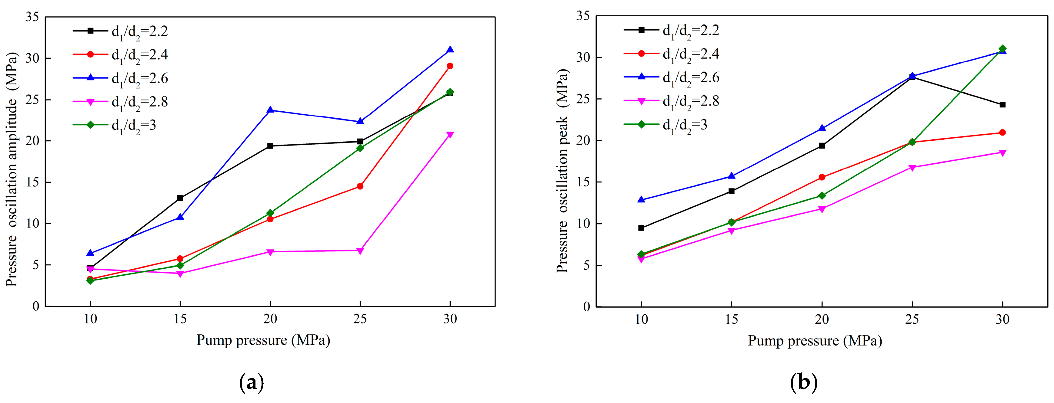
The maximal jet peak pressure and amplitude for different pump pressures are shown in
Figure 9. They were measured at the target distance of 20 mm. It can be seen from the two pictures that the best oscillation nozzle structure is
d1/
d2 = 2.6. The reason is that
d1/
d2 of the OH nozzle determines the fluid velocity and reflected wave frequency of the jet entering the oscillating chamber of the organ pipe. Only when the reflected wave frequency is the same or close to the natural frequency of the structure, will the jet produce significant resonance and oscillation effects.
4.2. The Effects of d2/d3 on Pressure Characteristics
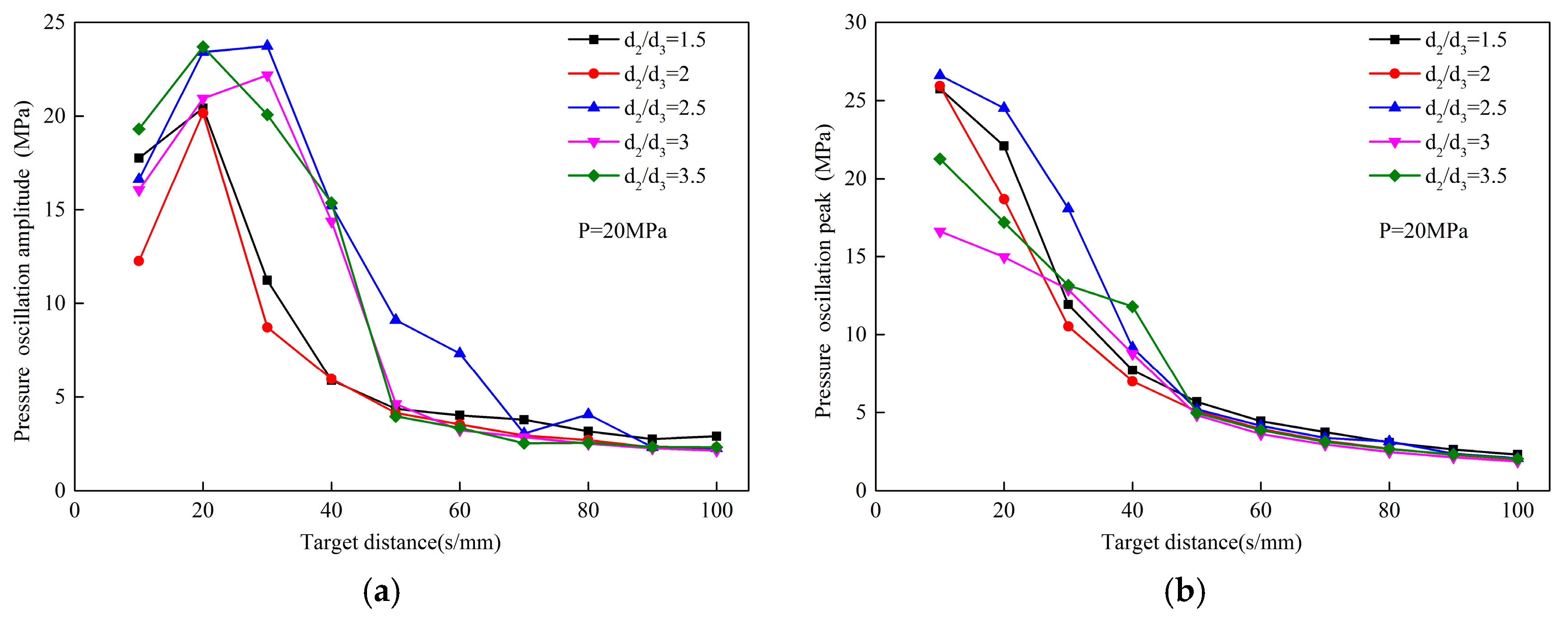
Figure 10 shows the peak pressures and pulsation amplitudes of different
d2/
d3 nozzles at the different target distances. Obviously, the change law here is similar to that discussed previously. It can be seen that the peak pressure is larger when
d2/
d3 is small. When
d2/
d3 increases, the performance of the nozzle will gradually deteriorate. Judging from the peak pressure, the performance of the nozzles is similar when
d2/
d3 is small. However, the variation law of pressure pulsation amplitude is different from that of peak pressure. When
d2/
d3 increases, pressure pulsation amplitude increases first and then decreases. Therefore, in comparison,
d2/
d3 = 2.5 is the best nozzle structure. Based on
Figure 11, the conclusion that
d2/
d3 has a more pronounced effect on jet pressure pulsation can be drawn. When
d2/
d3 is small, the pressure pulsation amplitude is significantly smaller. The main reason for this phenomenon is that
d2/
d3 will affect the space reflected by the jet after it enters the resonance chamber of the organ pipe and contacts the lower collision wall. This means that inside the nozzle,
d2/
d3 has a major influence on the jet velocity.
4.3. The Effect of L2 on Pressure Characteristics
Figure 12 shows the peak pressures and pulsation amplitudes of different
L2 nozzles at the different target distances. Their change law stays the same as the previous one. According to
Figure 13, nozzle performance first becomes better as
L2 increases, and then it deteriorates. It is obvious that
L2 = 4 mm is the best parameter. Meanwhile, according to the curves,
L2 = 6 mm nozzle also has relatively good performance when pump pressure is low. In fact, the best
L2 will be slightly affected by pump pressure.
Surprisingly, it can be seen that the pressure pulsation amplitude of L2 = 6mm nozzle is slightly higher than that of 4 mm when the pump pressure is lower. But nozzle performance of L2 = 4 mm is much better than that of the nozzle of L2 = 6 mm with the pump pressure increasing. In other words, the comprehensive performance of L2 = 4 mm nozzle is still the best.
This is because the jet enters into the surrounding fluid in the chamber in the Helmholtz oscillation cavity, and a tiny vortex is continuously generated at the boundary layer. The jet exchanges energy with the environmental fluid, and the degree of turbulence in the cavity increases with the cavity length. At the same time, the feedback generated from the downstream collision wall also exacerbates the attenuation of the axial velocity. When the cavity length is long enough, the ordered vortex ring formed in the jet shear layer has sufficient space to develop. Therefore, the feedback from the downstream collision wall back to the upstream can also be well amplified, which plays an important role in modulating the jet. However, as the cavity length continues to increase, the fluid of the axial center exchanges energy with the surrounding environment, causing a large loss. When this loss is greater than the modulation, the peak pressure and amplitude will decay.
It can be seen from this that flow in the Helmholtz resonance chamber is more complicated than that in the organ pipe resonance chamber. Therefore, the influence of inlet pressure cannot be ignored when designing the Helmholtz oscillation cavity structure.
4.4. The Effect of d4 on Pressure Characteristics
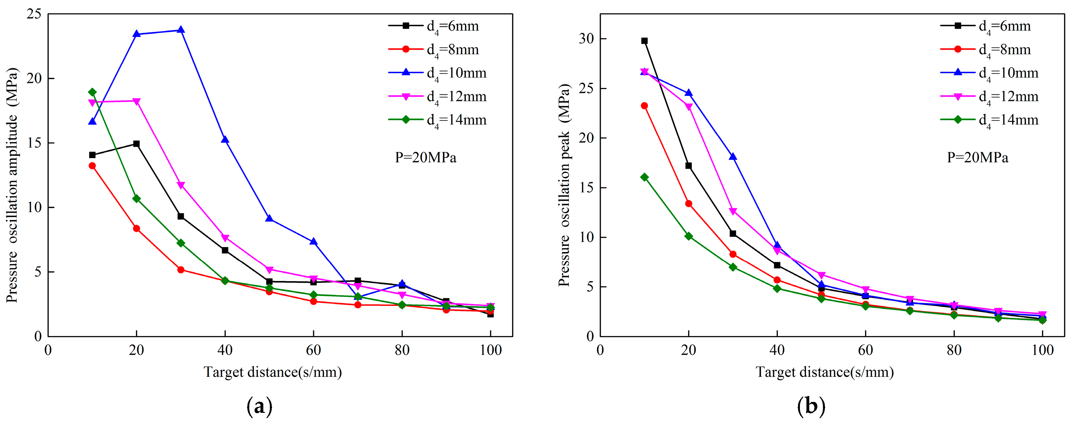
Figure 14 shows the peak pressures and pulsation amplitudes of different
d4 nozzles at the different target distances.
Figure 15 shows the peak pressures and pulsation amplitudes of different
d4 nozzles at different pressures. From the above peak pressure curves and pressure pulsation curves, it can be seen that the nozzle performance of
d4 = 12 mm is better than that of
d4 = 10mm when the pressure is low. However, with the pump pressure increasing, nozzle with
d4 =10mm has a better performance. This indicates that in the OH type self-excited nozzle, the optimal
d4 structure of the nozzle is extremely sensitive to changes in pressure.
For the Helmholtz nozzle, the vortex ring modulation coupling of the downstream collision wall feedback is mainly affected by d4. If the cavity diameter is too small, the jet will form a reflux vortex when it engulfs the surrounding fluid in the chamber and cannot be fully developed. This causes the chamber wall to be subjected to limited compression against the backflow of the chamber, resulting in increased energy consumption. If the cavity diameter is too large, the vortex is fully developed and the return flow is away from the jet axis, and the axial jet cannot be effectively modulated and coupled. So d4 = 12 mm nozzles have better performance when the pressure is lower. When the pressure is 20 MPa or more, the pulsation amplitude of the pressure produces a maximum at d4 = 10 mm.
4.5. The Effect of d3/d5 on Pressure Characteristics
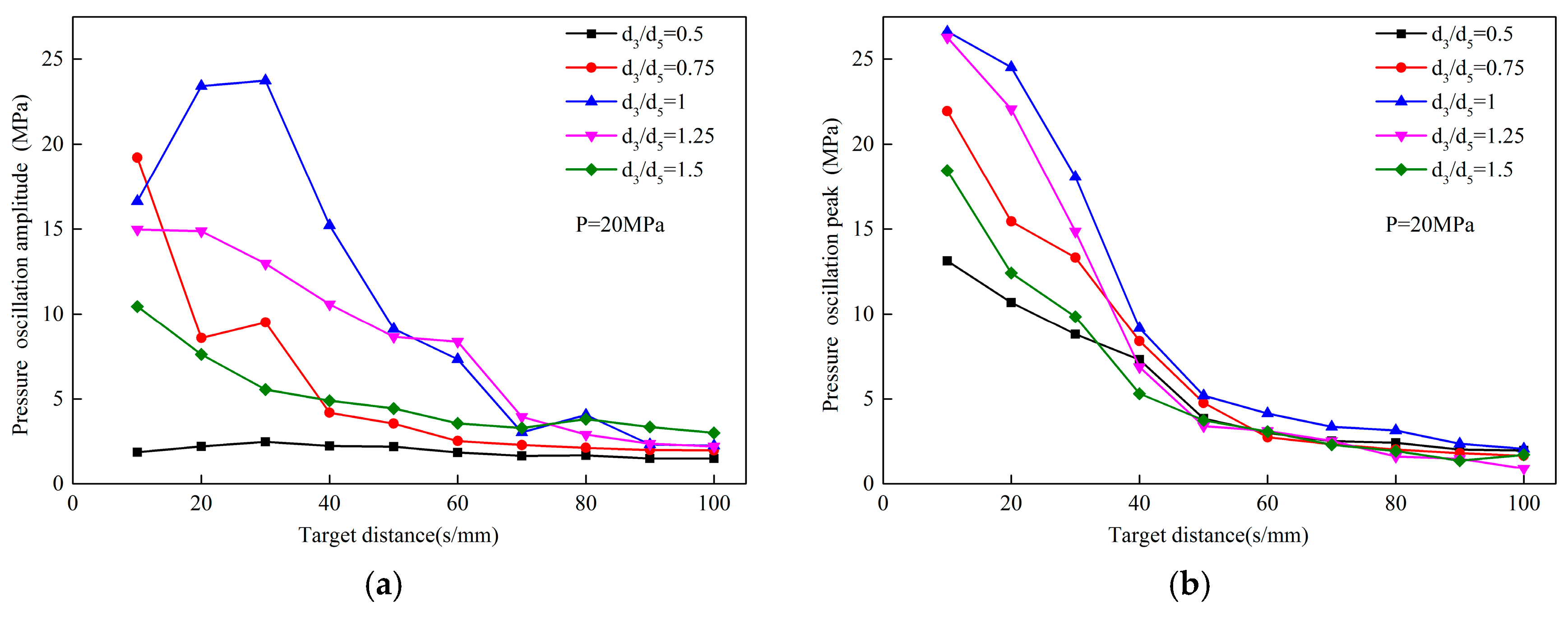
Figure 16 shows the effects of
d3/
d5 on the peak pressure and pressure pulsation amplitude of the OH self-excited pulse nozzle at the different target distances.
Figure 17 shows the effect of
d3/
d5 on the peak pressure and pressure pulsation amplitude of the OH self-excited pulse nozzle at different pressures. As can be seen from the two pictures, the jet peak pressure increases as the nozzle diameter increases at first, and then decreases. When the nozzle diameter ratio value is 1.0, the jet pulsation peak is the largest. The pressure pulsation amplitude of the jet shows a more sensitive change. When
d3/
d5 value is 0.5, the pressure pulsation amplitude is almost 5 MPa or less and keeps steady with the pump pressure’s increases. It indicates that the fluid does not oscillate when passing through the nozzle at such a time. As
d3/
d5 increases, the oscillation effect generated by the nozzle increases, reaching a maximum value when
d3/
d5 is 1.0.
When d3/d5 is small, only the innermost layer of the jet core zone can be ejected outward through the nozzle outlet. Most of the jets will only reciprocate continuously in the oscillating chamber, so it is almost impossible to form an oscillating jet. When d3/d5 is too large, the fluid in contact with the collision wall at the periphery of the jet is small, and the oscillation effect generated when propagating upward is insufficient to modulate the core region of the jet. Therefore, no obvious oscillating jets will form in this case.
5. Conclusions
OH nozzles (organ–Helmholtz nozzles) are novel self-oscillation nozzles. They do not just connect an organ-pipe nozzle and a Helmholtz nozzle together. They combine the two kinds of ordinary nozzles, and the synergistic effect of OH nozzles makes pressure fluctuations of self-excited jets more obvious. In this paper, the pressure oscillation characteristics of OH nozzles were investigated, and the conclusions were obtained as follows:
(1) Both the jet peak pressure and the pressure pulsation amplitude are positively correlated with the pump pressure. The jet peak pressure is inversely related to the target distance. As the target distance increases, the peak pressure first decreases sharply, and then decreases slowly. As the target distance increases, the pressure pulsation amplitude increases at first, and then decreases. Therefore, there is an optimum target distance, which is 20 mm in the experiment.
(2) Some of the optimal parameters of the OH nozzle are not sensitive to pressure. In this experiment, the performance of that nozzle regarding those parameters was the best regardless of the change in pressure. These parameters may be related to the initial perturbation vortex formation. The optimal parameters are d1/d2 = 2.6, d2/d3 = 2.5, and d3/d5 = 1.
(3) The optimum ranges of L2 and d4 are affected by pressure. They are closely related to the development of disturbance waves, and the oscillation pulsed jet can enhance and develop only in appropriate situations. L2 is relatively lightly affected by pressure. L2 = 6 mm has good performance when the pump pressure is low. When the pressure is increased, L2 = 4 mm performs better. Similarly, d4 = 12 mm performs well when the pressure is low. When the pressure exceeds 20 MPa, d4 = 10 mm performs better.

 ,
, 


