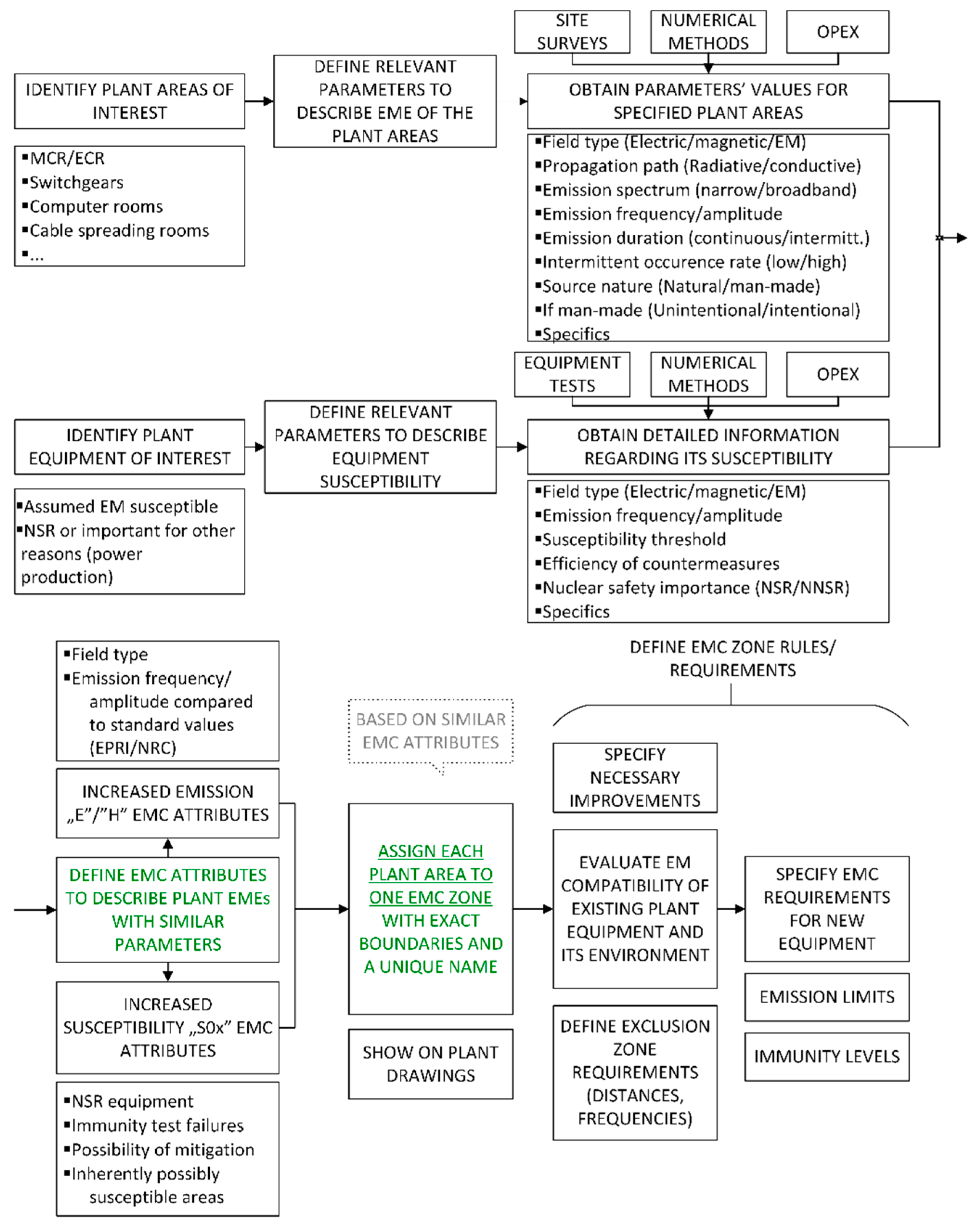
The combination of the operating records, in situ and bench immunity tests, site survey measurements, and numerical calculations can provide a reasonable amount of data to perform a systematic NPP room classification based on EMC conditions. Each of these inputs contributes in a specific way, as discussed below.
Historical data can help identify some of the key plant problems, which can later be confirmed through immunity tests, which could provide more detailed information about the susceptibility problems. Operating records can also help to define the exact scope of the immunity tests.
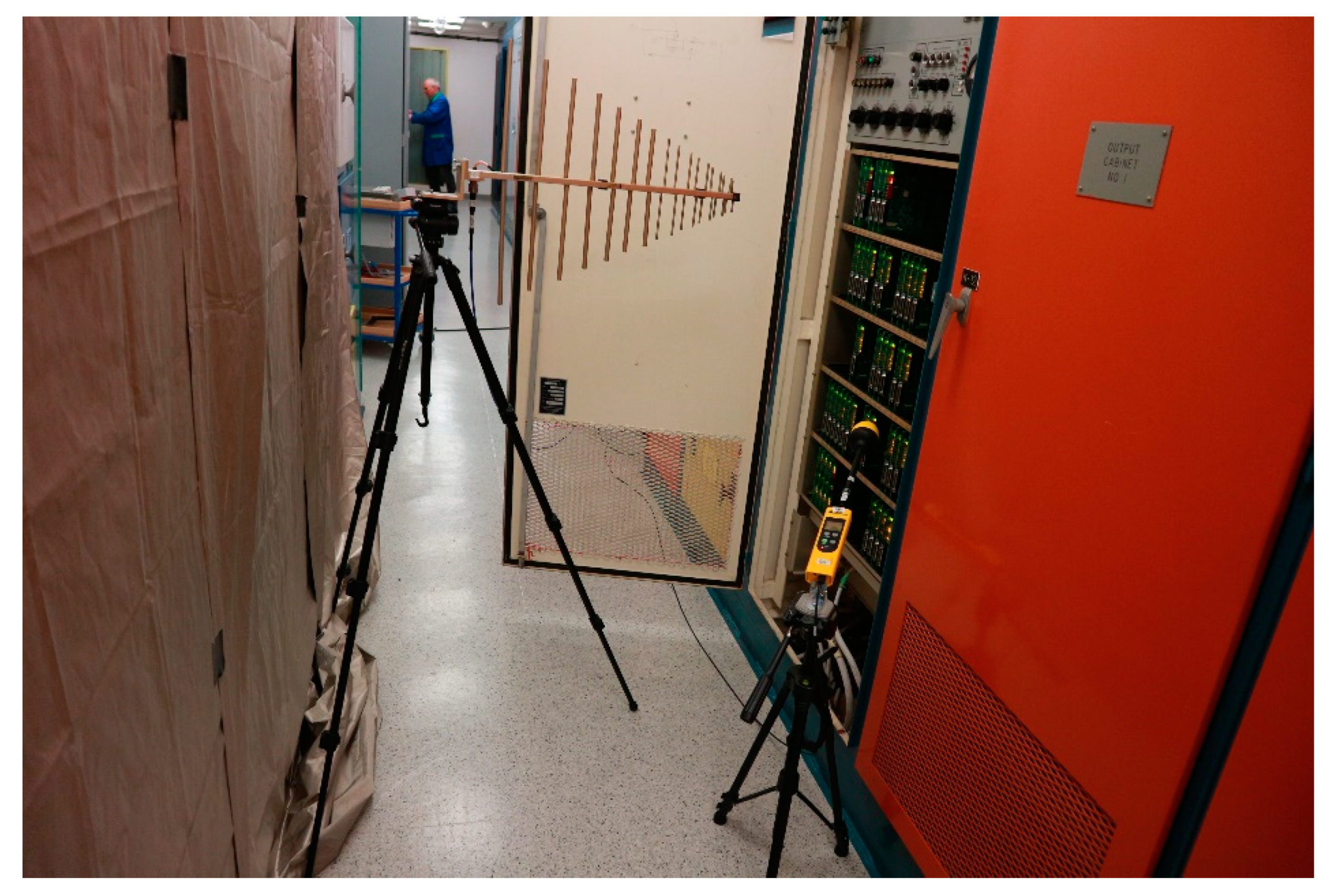
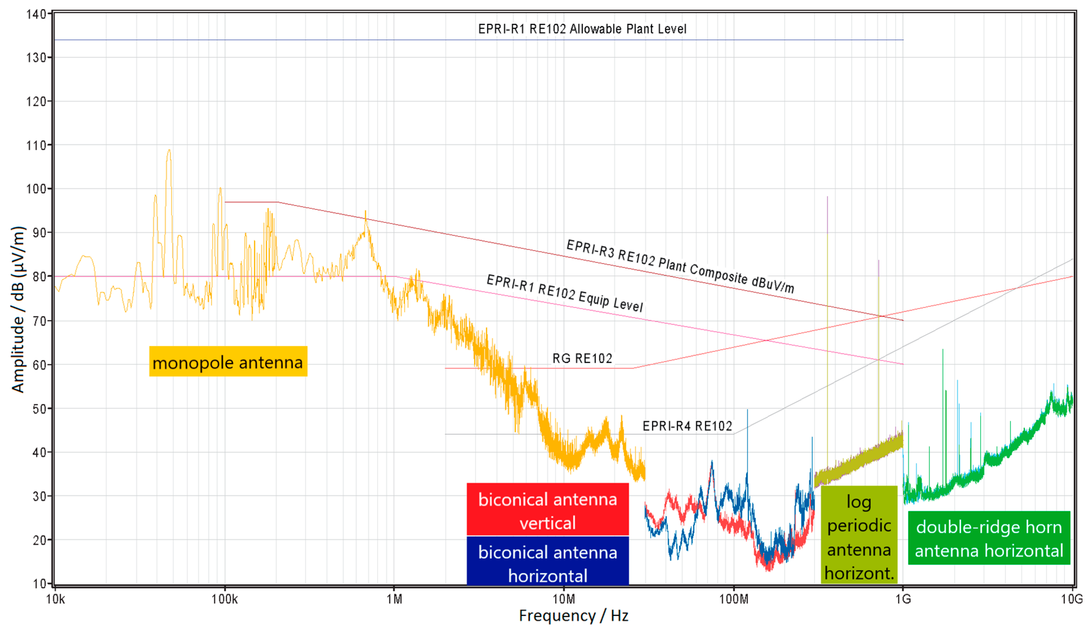
Site survey measurements can help to compare EM field levels in different areas of the plant, and can identify those with increased emissions. It is not only possible to recognize that some rooms have higher emissions, but also to precisely characterize the noise.
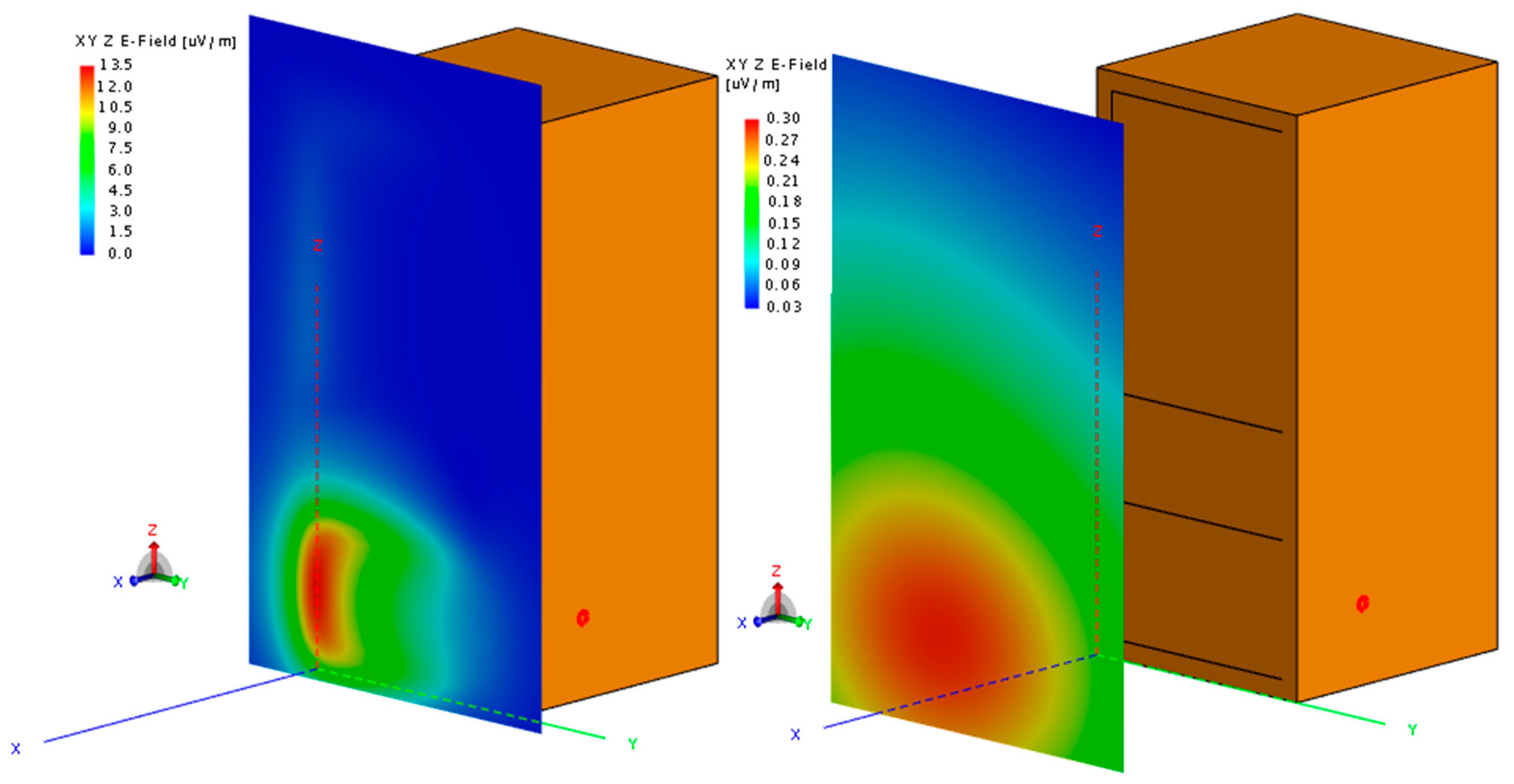
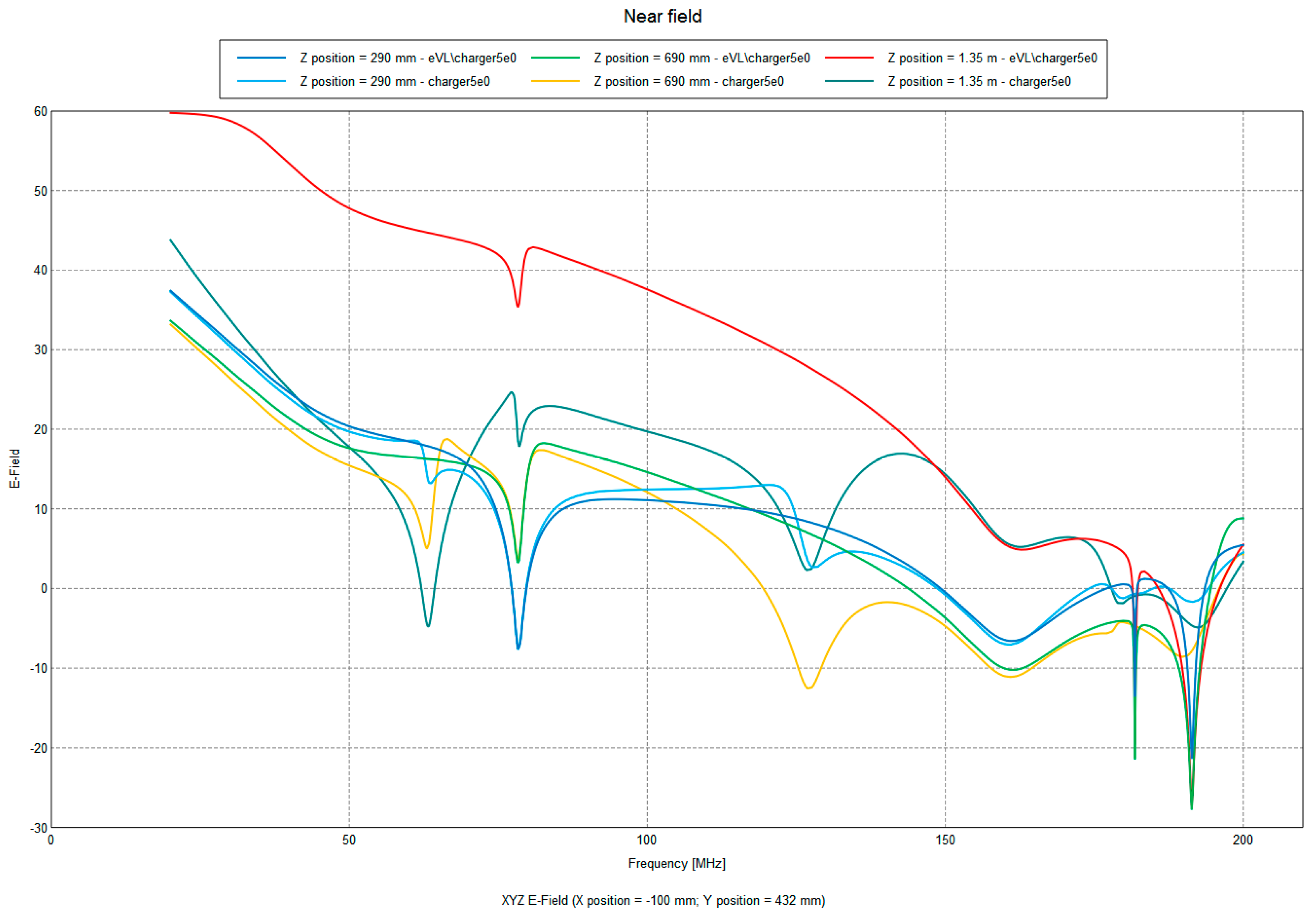
Site survey results are partially confirmed by and extended with numerical calculations, as it is not possible to perform measurements in a large number of plant locations. Numerical calculations of the cabinet shielding also provide useful information regarding the field attenuation, providing inputs for the design of the exclusion zones (i.e., definition of the exclusion distance from the susceptible equipment). They can also give information at which distance from the emitter the field values drop down to the acceptable levels, and predict improvements based on the design alterations.
The first process is related to the characterization of the plant areas from the EMC point of view. In order to perform that task, first, it is necessary to identify plant areas of the interest (i.e., all areas where either potential emitters are located, susceptible equipment is located, or which serve as the interconnection of the different equipment). This step will slightly reduce the scope of the observed areas and help focus on the important ones. Afterward, we proceed by defining relevant parameters to describe the EME of the plant areas, which should:
Such a set of parameters can include the dominant field type (electric, magnetic), propagation path (radiated, conducted), emission spectrum (narrowband or broadband), emission frequencies and amplitudes, emission duration (transient or continuous), and nature (natural, man-made: unintentional or intentional). The parameters are obtained through a combination of previously discussed techniques.
The second part of the process is related to the characterization of the susceptible equipment. It is done in a similar manner as for the plant areas and it starts with the identification of the potentially susceptible equipment. The next steps are also similar. It is necessary to define the relevant parameters that can describe the susceptibility (immunity) of the I&C equipment and obtain the values of those parameters. The choice of parameters is similar to that discussed for EME characterization.
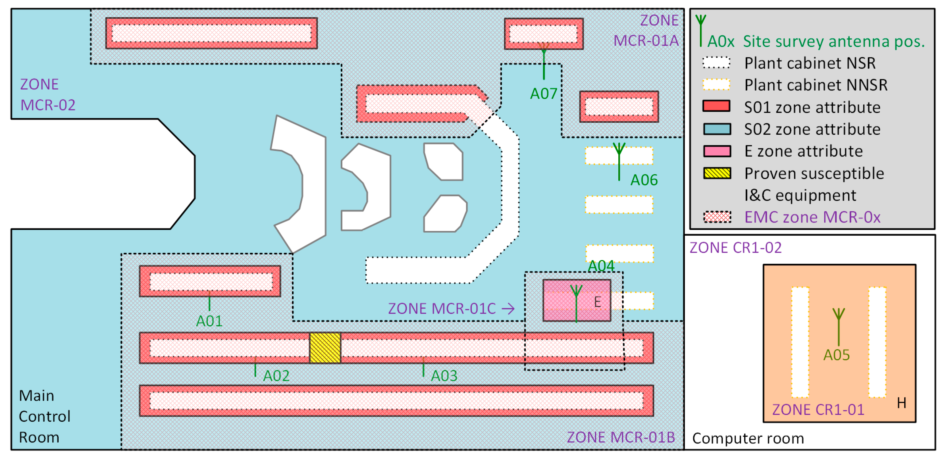
Finally, the locations with similar EMC attributes are called an EMC zone. The EMC zone has well-defined boundaries shown on the plant layout drawings and a unique identification number, similar to that undertaken for the previously mentioned EQ methodology.
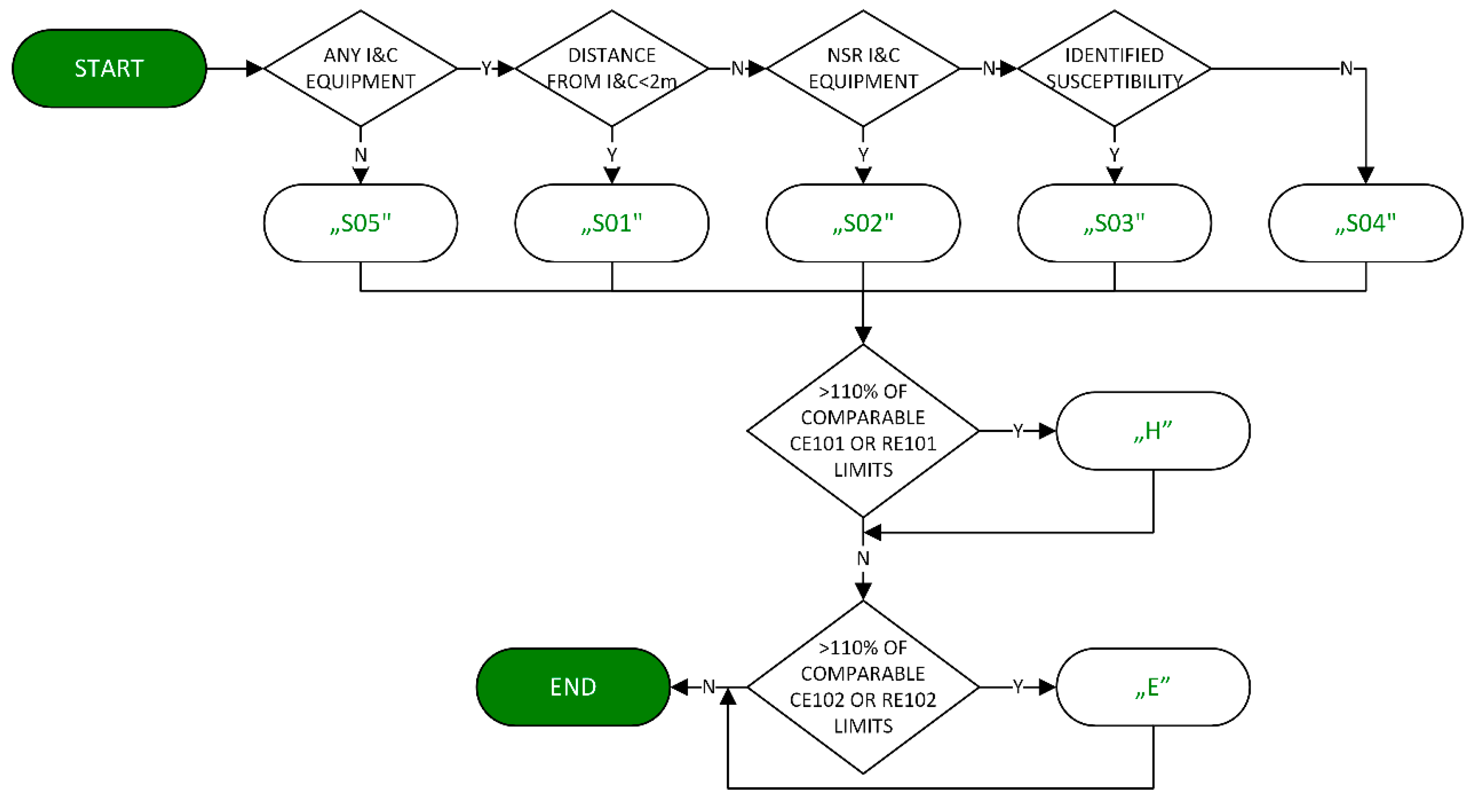
EMC Attributes
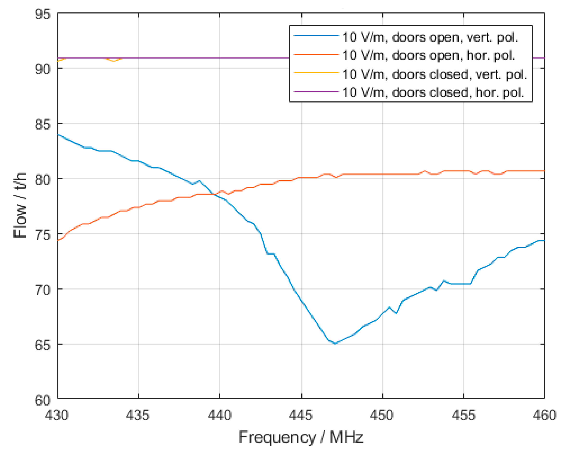
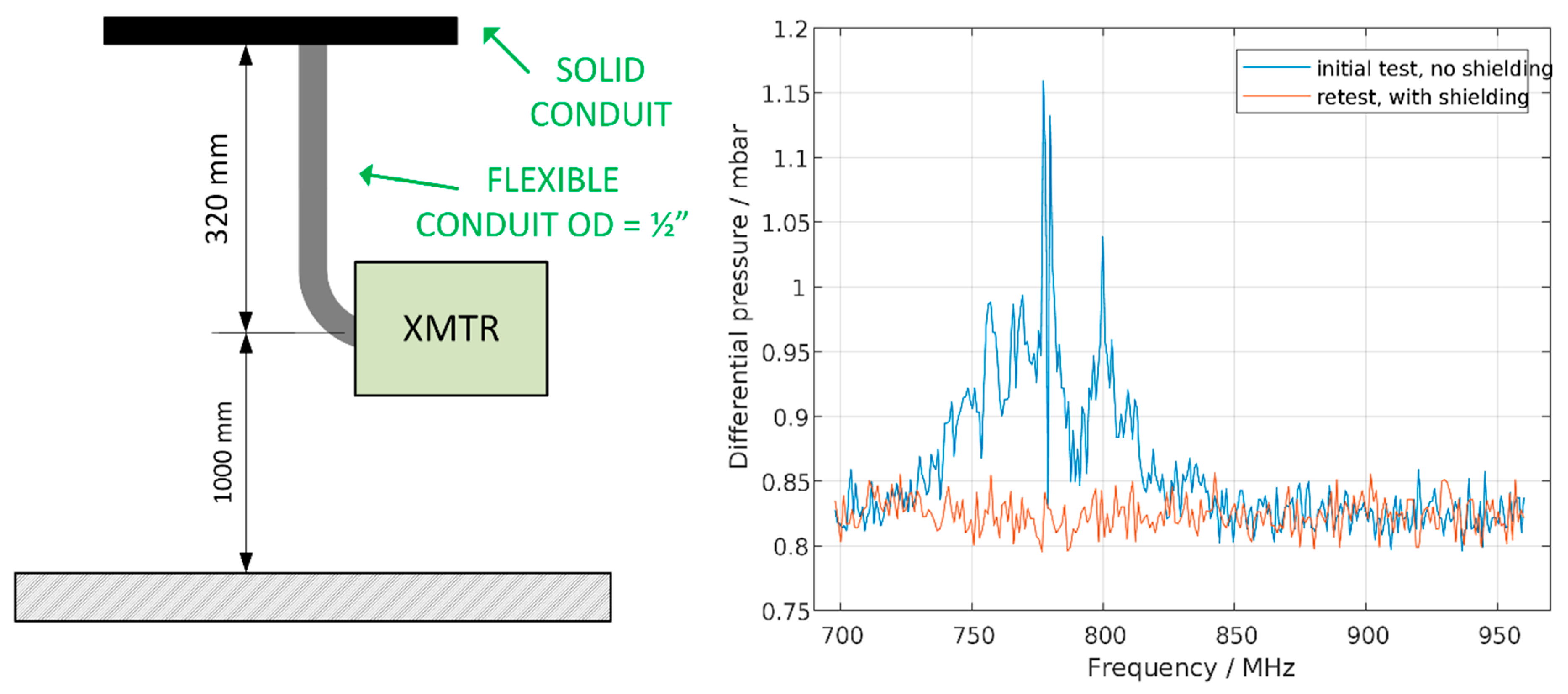
Immunity tests and numerical calculations have proven that the use of communication devices is not allowed under any conditions for most of the operating cabinets with the doors open. Taking that into account, all susceptibility attributes are assigned to the configuration where the cabinet doors are closed.
1. Susceptibility attribute 1 (S01)
Special attention must be paid to the area near the sensitive plant equipment. The S01 zone attribute primarily encompasses a distance up to two meters from all nuclear safety-related plant cabinets and I&C instrumentation. It is set for all emitters, regardless of the emission frequency, since it is not related to an identified vulnerability, but to the fact that the possibility for interference rapidly increases for smaller distances between the emitter and victim.
The above-mentioned distance of 2 m was obtained in the following way. Immunity tests were performed using a predefined electric field strength, which was 10 V/m or higher for the selected equipment under test (EUT), as defined by the regulatory requirements. If the EUT successfully passed the test, the exclusion zone around it was defined. First, a safety margin of 8 dB was used to eliminate uncertainties related to the EME and address that it is always possible to expose the equipment to higher field values than it was tested for. The emitter output power might be higher, or the distance to the plant equipment might be smaller. If the test E-field strength is 10 V/m, the allowed E-field strength is 4 V/m in this case.
It is possible to estimate the exclusion zone around the tested equipment using the equation below [
9]. The equation relates the maximum allowed strength of the electric field
E (in V/m), the measured output power of the test system
Pt (in watts), and the test antenna gain
Gt (dimensionless), with the minimum exclusion zone distance
D (in meters).
For typical values of Pt and Gt for the plant radios, the calculated exclusion distance was 1.37 m. We performed immunity tests on plant components using appropriate E-field strengths. Then, for different emitters such as plant radios, mobile phones, and Digital Enhanced Cordless Telecommunications (DECT) phones, we calculated the minimum exclusion distances. None of the calculated distances exceeded 2 m. Therefore, this value was taken as the unique exclusion zone for all I&C equipment.
Although it could be obviously relaxed for some equipment, it is more practical to define a unique exclusion zone for all equipment (which is here conservative compared with the minimum recommendations given by EPRI—1/3 m), instead of defining it for each piece of equipment separately. The proposed distance is acceptable as a compromise between achieving EMC immunity and not limiting plant personnel at the same time. For some cases, it is reduced several times from what was previously defined as a minimum exclusion zone (often, the whole plant rooms or at least significantly larger distances from the susceptible equipment are excluded).
Numerical calculations (field spatial distribution examples) and empirical formulas confirmed that the field attenuation is in accordance with Equation (1). It is known that both the electric field and the magnetic field attenuate rapidly (1/r3 and 1/r2, respectively) in the near-field region, and 1/r terms begin to dominate in the equation for the field intensity in the far-field region. For example, the far-field region typically begins 10–20 cm from the plant radios, depending on their operating frequency. Hence, it is critical to prevent the use of emitters in the proximity of the I&C plant equipment.
Only a fraction of all of the plant I&C equipment was tested. Hence, although the tested equipment might be representative, one must be aware of the limitations of such assessment. The exclusion distance could also be larger if some equipment did not pass some of the immunity tests.
In addition to the intentional emitters that are usually controlled administratively, it is necessary to strictly control and minimize the use of the unintentional emitters, which could easily affect the susceptible equipment. This implies the use of higher qualification emission requirements for the newly installed equipment, particularly RS103 and the corresponding IEC EN61000-4-3 [
10] tests. However, the first option is always to find a more appropriate installation location for such equipment. Every modification of the existing NSR I&C cabinets should be evaluated from the EMC point of view. It is recommended that universal immunity improvement measures are applied, which are valid for all installations such as the use of fine meshes to minimize enclosure openings and eliminate non-metallic enclosures.
2. Susceptibility attribute 2 (S02)
The S02 susceptibility zone attribute is assigned to plant areas where the susceptible or potentially susceptible nuclear safety-related I&C equipment was identified. Identification of these areas is strongly supported by in situ immunity tests.
Unlike the S01 zone attribute, the restrictions for the S02 zone attribute only apply to frequencies below 1 GHz, mostly based on the results of the immunity assessment.
Again, no severe emitters should be installed in these areas, and modification should include a comprehensive EMC review. Immunity requirements should be on the same level as for the S01.
The central, and from the EMC point of view, the most important area of the plant, is the main control room (MCR), followed by its counterpart the emergency control room (ECR) as well as the plant computer rooms. There, the most important instrumentation readings and controls are wired. Other specific areas are the cable spreading rooms. These are two separated plant areas, one for control cables, and the other for the power cables, through which most of the plant cables are routed. Although almost no equipment is placed there, cables can easily pick up the EM noise and reradiate it, causing unpredictable interference in other, remote plant areas. While administrative restrictions related to the use of the plant radios and similar devices can affect communication efficiency of the plant personnel in other plant areas, it might be an acceptable and efficient solution for cable spreading rooms.
3. Susceptibility attribute 3 (S03)
Another attribute, designated as S03, relates to the rooms where the susceptible non-nuclear safety related (NNSR) equipment were identified. The EMC attribute was assigned even if an acceptable solution to mitigate or completely cancel interference by modifying the EUT design or installation was found.
Identification of these areas is also strongly supported by in situ immunity tests.
The first step to improve the equipment immunity in those areas is by applying a simple design and installation enhancements, some of which like shielding effectiveness can be confirmed with numerical calculations. Afterward, the requirements for the new equipment should be defined. It is reasonable to use stricter emission requirements when qualifying this equipment. These increased requirements should be limited to the frequencies for which the susceptibility is identified. It is defined as an exclusion zone for the specific frequencies of interest (i.e., for the specific emitters only, usually plant radios or mobile phones).
4. Susceptibility attribute 4 (S04)
The most relaxed requirements are defined for plant areas where no immunity problems have been detected and no nuclear safety-related equipment is located. These are designated as S04.
As already said, there are no regulatory requirements for the immunity of the NNSR equipment.
However, in order to minimize the nuisance of the plant personnel caused by false alarms or readings, it is recommended to keep the equipment immunity at least reasonably high compared to the rest of the plant. This is the candidate area for the installation of the largest emitters, as long as the emissions are contained by using line filters, shielding, and similar. No exclusion zone rules apply for these plant areas.
For example, a large part of the turbine building could be characterized as such.
5. Susceptibility attribute 5 (S05)
The last zone encompasses plant areas where no I&C equipment is located, or is very limited and not important for nuclear safety. Such areas mostly contain piping or mechanical components with no instrumentation. These areas could be designated and treated as “RF safe areas”, as similarly described in EPRI TR-102323 [
9]. No exclusion zone rules nor any restrictions apply for this zone.
A brief summary of the above described susceptibility zone attributes is given in
Table 1.
6. E-field emission attribute (E)
The site survey identified several plant areas that had higher than average electric field emission levels. The criterion for increased emissions was set to approximately 10% above the comparable regulatory emissions limits. As the site survey provided field values for only a limited number of discrete locations, it was necessary to extrapolate the results for the rest of the area by approximating it with the field propagation equations and verifying them with the numerical models. The size of the increased emission areas was defined so that the field values on the zone boundary were approximately 20% below the comparable emissions limits.
Unlike the magnetic field, it was proven and shown in this paper that the E-field emissions interfere with different I&C equipment. In order to encounter this kind of interference, it is necessary to have an E-field source, which is a high impedance (high voltage, low current) source, and electrically small dipoles that can pick-up E-fields.
It is generally recommended to avoid these locations for the installation of new equipment if possible. If this is not possible, at least it is necessary to qualify the equipment for higher immunity levels (RS103 and corresponding IEC EN61000-4-3 [
10] tests). It is also recommended that tests are extended for the new and existing equipment above 1 GHz (up to 10 GHz), even though this might not be requested by some standards. For this purpose, in situ or bench tests could be performed, or the present E-field emissions could be analyzed, in order to prove that they do not pose a threat.
7. H-field emission attribute (H)
There are plant areas where the values of the H-field are significantly increased, similar as described for the E-fields. Very little equipment in the plant is susceptible to magnetic fields, and this type of interference is much more important for some other applications such as the navy (low frequency acoustic systems and extremely low frequency (ELF) to LF communication systems and sensors). In order to encounter this kind of interference, it is necessary to have an H-field source, which is a low impedance (low voltage, high current) source and electrically small loop antennas that can pick-up H-fields. Some examples of susceptible equipment are cathode ray tubes and Hall Effect sensors. The latter are used for proximity sensing, positioning, speed detection, and they have an output voltage that is directly proportional to the magnetic field strength through it. Except for the mentioned equipment, it is possible to relax installation restrictions in areas with high magnetic fields, which are quite often in the plant. These are usually in the vicinity of the high current carrying conductors and power electronics. RE101 plant measurements have confirmed that these can be found in the vicinity of uninterruptible power supplies (UPSes) and diesel generators. It is recommended to qualify equipment intended for installation in these areas for higher magnetic field immunity levels (RS101 and corresponding IEC EN61000-4-8 [
11], IEC EN61000-4-9 [
12], and IEC EN61000-4-10 [
13] tests). It is important to pay attention to the selection of the enclosure materials for the equipment installed in this area, and use ferromagnetic materials where possible. Zones of increased E- and H-field emissions should be physically marked in the plant.


