Review

Thermal Energy Storage for Grid Applications: Current Status and Emerging Trends

1
Electronics Telecommunications and Energy Department, University Valahia of Targoviste, 130004Targoviste, Romania
2
Wing Computer Group srl, 077042 Bucharest, Romania
3
Dipartimento Energia “Galileo Ferraris”, Politecnico di Torino, 10129 Torino, Italy
4
Power Engineering Systems Department, University Politehnica of Bucharest, 060042 Bucharest, Romania
5
Department of Measurements, Electrical Devices and Static Converters, University Politehnica of Bucharest, 060042 Bucharest, Romania
*
Author to whom correspondence should be addressed.
Energies 2020, 13(2), 340; https://doi.org/10.3390/en13020340
Submission received: 31 December 2019 / Revised: 7 January 2020 / Accepted: 8 January 2020 / Published: 10 January 2020
(This article belongs to the Section A: Sustainable Energy)

Abstract

:
Thermal energy systems (TES) contribute to the on-going process that leads to higher integration among different energy systems, with the aim of reaching a cleaner, more flexible and sustainable use of the energy resources. This paper reviews the current literature that refers to the development and exploitation of TES-based solutions in systems connected to the electrical grid. These solutions facilitate the energy system integration to get additional flexibility for energy management, enable better use of variable renewable energy sources (RES), and contribute to the modernisation of the energy system infrastructures, the enhancement of the grid operation practices that include energy shifting, and the provision of cost-effective grid services. This paper offers a complementary view with respect to other reviews that deal with energy storage technologies, materials for TES applications, TES for buildings, and contributions of electrical energy storage for grid applications. The main aspects addressed are the characteristics, parameters and models of the TES systems, the deployment of TES in systems with variable RES, microgrids, and multi-energy networks, and the emerging trends for TES applications.

1. Introduction

Energy storage is one of the crucial aspects of the ongoing transition towards more efficient and sustainable energy systems. It depends on the availability and controllability of redirecting all or part of the energy flows to a suitable storage system, then using the stored energy when needed. Without storage, the traditional view of the energy services is one of a just-in-time commodity, where the generation follows the load (also covering the energy losses). The introduction of storage at different levels modifies the energy exchanges (input from or injection into) in the networks and is changing the paradigm from a just-in-time to a time-adjustable commodity, virtually up to the condition in which the load follows the generation (also considering its uncertainty, whose variability should be smoothened by using storage). This broadened range of applications enables the participation of consumers that are also local energy producers (i.e., the prosumers) in the provision of energy services to different types of energy markets, including new forms of local energy markets [1] and energy communities [2], which are being envisioned.
Energy storage is also a key component of decarbonisation scenarios, such as the ones indicated in the European Roadmap to 2050 [3], whose main targets include high energy efficiency, diversification of the production resources, and increase in the percentage of renewable energy sources (RES). In the Roadmap, the share of renewables rises substantially in all scenarios, achieving at least 55% in gross final energy demand in 2050. Various types of storage (not only of energy) are considered, such as pumped hydro storage, hydrogen storage, and carbon capture and storage, with significant development of smart infrastructures including electrical storage. The main objective is the increment of the flexibility of the system from various points of view, i.e., with energy efficiency improvement (also in multi-energy systems and markets) and energy network management (dealing with planning and reinforcement of the system, provision of reserves, increase of stability, reduction of vulnerability, enhancement of the frequency control effectiveness, energy flows and voltage control, and reduction of the network disturbances). Further targets include reaching environmental goals on greenhouse gas emissions reduction and improvement of the air quality, as well as social goals, e.g., empowering the consumers as indicated in the “Clean Energy for All Europeans” Package [4], or more generally satisfying the Sustainable Development Goals [5] issued by the United Nations General Assembly [6]. To obtain this main objective, the best mix of technologies to operate the energy systems has to be identified.
The presence of storage systems increases the variability of the demand seen at the energy network terminals. In fact, the shape of the net demand patterns becomes more and more variable and in principle, less predictable. On the supply side, the evolution towards higher renewable energy generation leads to higher fluctuations in the RES systems outputs, needing appropriate storage to smooth these fluctuations, by storing the supplementary energy generated and releasing it when there is an excess of demand with respect to the generation currently available. Energy storage is useful to reduce the demand peaks, to provide back-up power when a blackout occurs, and to operate the grid more efficiently (with lower currents in the network branches, thus lower network losses).
The energy storage technologies are classified, by considering the form of stored energy, into mechanical, electrical, electrochemical, chemical, and thermal [7,8,9,10,11,12]. This paper is focused on the applications of thermal energy storage (TES) to enhance the operation of the electrical networks. From the literature, several reviews and contributions are available on the applications of TES to buildings, combined heat and power (CHP), district heating, and other thermal systems [13,14], and on the materials used in TES applications [15,16]. At the same time, several articles, reviews and reports address various types of electrical energy storage for grid applications [17,18,19,20]. This paper offers a complementary view with respect to previous reviews, by addressing the deployment of TES in systems connected to the electrical grid, to enable better use of the variable RES and provide energy services to the grid. In these cases, the number of TES applications is much lower. However, there is a growing trend to develop electric thermal storage and incorporate TES as a solution that allows multi-energy system integration and can enhance the operational flexibility of the power and energy systems that operate in traditional environments or in the new context of local energy systems or energy communities.
The next sections of this paper are organised as follows. Section 2 recalls the characteristics of TES systems, the typical parameters considered for their evaluation, the energy services provided, and TES modelling aspects. Section 3 presents the categorisation of the TES technologies. Section 4 deals with the exploitation of TES with variable RES. Section 5 summarises the TES applications in microgrids and multi-energy networks. Section 6 indicates some emerging trends for TES applications. The last section contains the concluding remarks.

2. Thermal Energy Storage Systems, Performance Parameters and Models

2.1. Characteristics of the TES Systems

TES is the technology that allows the temporary storage of thermal energy at low or high temperatures [8] by cooling or heating a storage medium (in a thermal reservoir/tank) in a determined period. The stored energy is later used, after hours, days or months, in heating or cooling applications and power generation. The temperature of the storage medium is maintained at a temperature higher (hotter) or lower (colder) than the ambient temperature. The TES advantages are low carbon footprint and energy demand; low cost of TES system and its maintenance costs; low pollutant emissions; good flexibility in operation; isothermal and superior storage capacity per unit weight; and energy from any thermal or electrical source when required [21]. The TES drawbacks are the relatively low efficiency of the TES system and thermal standby losses (thermal losses between the storage medium and the environment) [11].
The characteristics of TES systems are different with respect to other forms of storage. As such, the types of services that may be provided are only the ones that fit with the TES characteristics. In particular, with respect to electrical energy storage, which can provide relatively fast services at sub-second time scale, e.g., for power quality improvement, grid stability enhancement, and short-time backup power [22,23], a TES system has slower response due to its intrinsic thermal capacity that affects the thermal transients [24]. At the same time, heat (or cooling) cannot be stored for a long time, because of the thermal losses due to the difficulty in insulating the storage devices. For long-term or seasonal storage, TES could be an unsuitable or at least low-priority option to store the power surplus coming from the electrical network, the higher priorities being given to batteries, pumped hydro storage (PHS) or compressed air energy storage (CAES), power-to-gas (P2G) or hydrogen, and use in electric heat pumps [25]. Natural gas could also be considered for storage, however, with the drawback of the CO2 emissions due to the use of natural gas in the boilers [26].
TES systems aimed at reducing the power demand in peak periods are found in centralised systems (associated with CHP, district heating and cooling, large industrial plants, or RES), or in distributed systems (for residential or commercial buildings) [27]. In order to increase the TES life, coordinated control options with multiple CHP systems may be set up by reducing the TES participation in the system operation [28]. Cold TES is a distributed type of TES that uses refrigeration and air conditioning technologies controlled through a virtual power plant to provide load shifting. Cold TES has been significantly addressed for peak load shifting in applications to commercial buildings [29] and cities with semiarid areas [30].

2.2. Parameters of the TES Technologies

Three main parameters are used to represent the TES technologies:
  • The operating temperature of the energy storage material compared with the indoor temperature: for this purpose, there are low-temperature TES material and high-temperature TES material. Examples could be building heating (25–50 °C), building cooling (0–12 °C), industrial cooling (less than −18 °C), and industrial heat storage (over 175 °C) [31].
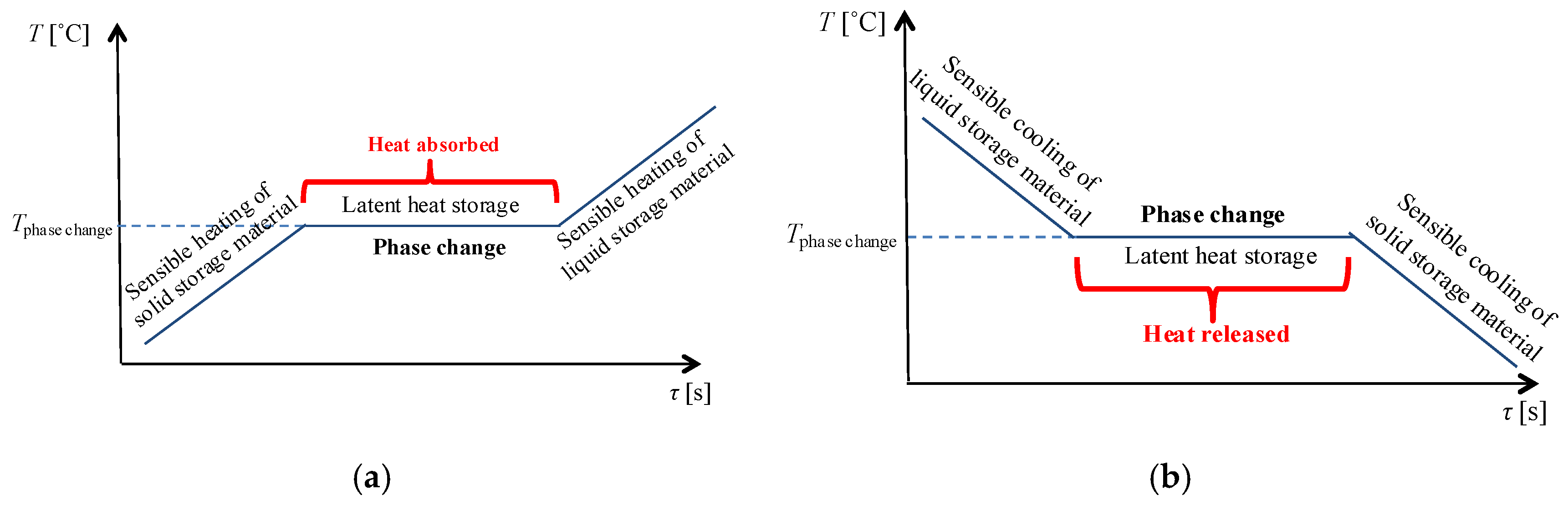
  • The state of TES material: a distinction is made between sensible heat storage and latent heat storage. The sensible heat is the heat that determines a temperature change (increase or decrease) in a thermal storage material, without changing its chemical composition or phase. The latent heat is the heat that determines the phase change (the transition from solid to liquid or from liquid to vapour) in a thermal storage material without modifying the storage material temperature (Figure 1). A phase change takes place in a thermal storage material during heat exchange without variation in the material chemical structure. During the phase change, the heat could be absorbed (in the melting process) or released (in the freezing process).
  • The time period of the stored thermal energy: the time periods are short-term (diurnal thermal storage) and medium or long-term (seasonal or annual thermal storage) [12]. Short-term TES is used to shift peak power loads from a couple of hours to a day, to reduce the sizing of the system and obtain economic benefits from time-variable energy tariffs or prices. Medium-term and long-term TES refers to seasonal energy storage, in which a delay from a few weeks to some months is considered [32].
The main performance parameters of a TES system are:
  • Power capacity (W) is the maximum amount of power that can be delivered by the storage system during discharging;
  • Power density (W/l) is the ratio between the power capacity and the capacity of the energy storage system;
  • Energy storage capacity (Wh), also identified as energy capacity, is the amount of energy absorbed in the storage system during charging under nominal conditions;
  • Energy density or volumetric heat capacity (Wh/L, or Wh/m3) is the ratio between the stored energy and the volume of the energy storage system;
  • Storage period (from hours to months) indicates the duration of the storage period;
  • Response time (from seconds to minutes) is the time speed with which the energy is absorbed or released in the storage system;
  • Cycling capacity (number of cycles) is how many times the storage system releases the energy after each recharge;
  • Cycle life is the maximum number of charge-discharge cycles in specified conditions;
  • Discharge rate is the rate at which the stored energy is discharged;
  • Self-discharge is the amount of energy initially stored and after dissipated over a specified non-use time;
  • Round-trip efficiency (RTE) or cycle efficiency η, is defined as η = Eout/Ein, where Ein is the energy needed to charge the system and Eout is the energy remaining after a charge-discharge cycle; the self-discharge losses during the operation of the storage system in idle mode are not considered in the definition [33,34];
  • Costs are defined with reference to the energy storage capacity (€/kWh) or power capacity (€/kW) of the storage system, and consider capital costs, and operation and maintenance costs of the storage equipment during its lifetime;
  • Cost per output (useful) energy is the cost per unit energy divided by the storage efficiency;
  • Per cycle cost is the cost per unit energy divided by the cycle life [12,35].

2.3. Energy Services Provided by TES Systems

The main applications of TES are peak shifting, heat transport, renewable sources, waste heat, or natural cold [36]. TES systems are used to store waste heat in the form of thermal energy to satisfy the energy required [10]. TES systems are used to correct the discrepancy between load and supply of thermal energy and, for this reason, are important for RES integration [8]. Furthermore, TES systems are useful to reduce peak demand, CO2 emissions, energy demand, and costs of the energy system, while its overall efficiency is improved. A TES system uses three modes of operation: charging, storage (idle mode) and discharging (Figure 2).
In the charging mode, the energy is supplied to the TES system. In the storage mode, the energy is stored in the TES system (with the corresponding internal losses), while in the discharging mode the energy is released from the TES system to the thermal load for further utilisation. The energy storage must have adequate power capacity and energy capacity [12].
The main energy services provided by TES technologies include [4]:
  • The decoupling of generation and demand for heat and cooling with respect to the power demand.
  • The increase of energy efficiency in the energy system, for example by storing industrial waste heat that would otherwise be lost.
  • The reduction of the greenhouse gas emissions in the heating and cooling sector, obtained by enabling the use of a larger amount of renewable energy taken from wind, solar thermal and photovoltaic, biomass, and geothermal technologies.
  • The increase in flexibility and security of supply, because of the availability of supplying heat and power when the demand is high, at relatively low cost.

2.4. Modelling Aspects

The notation used here has been unified with respect to the many notations used in the literature to represent the same modelling aspects. The TES model indicated in this section represents different operation modes (charging, discharging, and idle). Following the generic deterministic storage model [37], the TES model is formulated by considering a sequence of time steps k = 1, …, K with the regular time step Δ t k , considering the following entries: the energy E k stored at time step k, the power P c h , k with which the storage unit is charged at time step k with charging efficiency η c h , and the power P d c h , k with which the storage unit is discharged at time step k with charging efficiency η d c h . Moreover, the per-unit internal losses k model the self-discharge occurring during the time step Δ t k , and represent the non-ideality of maintaining the energy stored in idle mode conditions [38]. Furthermore, the binary variable u k is introduced to avoid simultaneous charge and discharge, with u k = 1 during charge and u k = 0 during discharge.
The energy stored at the successive time step k + 1 in the storage device is then expressed as:
E k + 1 = ( 1 u k k )   E k + η c h P c h , k Δ t k P d c h , k η d c h Δ t k
The energy E k also corresponds to the state of charge (SoC) of the storage system, which may be expressed in per units (or in per cent) by dividing it by the energy capacity E ^ of the storage system:
S o C k = E k E ^ ;   S o C % k = 100   E k E ^
By introducing the power capacity P ^ of the storage system, the constraints on the charge and discharge power values are given by:
P c h , k   u k P ^
P d c h , k ( 1 u k )   P ^
The impact of the ramp constraint R k (in per units) on the charge and discharge during the time step Δ t k can be expressed in terms of the S o C k as in [39]:
R k Δ t k S o C k + 1 S o C k R k Δ t k
The idle operation of the TES is modelled by assuming u k = 1 and P c h , k = 0, so that the reduction in the energy stored is represented by the effect of the per-unit internal losses k .
Furthermore, the minimum limit E ˇ K and the maximum limit E ^ K are imposed on the final energy stored in the TES at the end of the study period (k = K):
E ˇ K E K   E ^ K
The general form (6) to represent the final energy stored in the TES is extended with respect to the constraint of having the same energy at the beginning and the end of the study period, used in various references, e.g., [40,41,42]. This extended form is more suitable to be incorporated into calculation tools that use uncertain or predicted values, for example, within an approach based on model predictive control (MPC).
Detailed TES models have been formulated in [43,44] by considering heat transfer constraints. These models can be used for sensible heat storage and latent heat storage (see Section 3.1) with different parameters. The presence of non-linear heat transfer constraints is solved with iterative calculations. The results show that latent heat storage can provide more flexibility than sensible heat storage, in particular with low initial thermal energy level. For a TES composed of a water tank, the model shown in [45] considers the volume of water in the tank as the relevant variable for the energy balance, assuming that the temperatures of the hot and cold water are constant during the time step of interest. A further detailed model of a TES composed of a high-temperature section and a low-temperature section is described in [38].

3. Types of Thermal Energy Storage Technologies

3.1. Categorisation of the TES Technologies

TES technologies can be partitioned into three categories:
  • Sensible heat storage
  • Latent heat storage
  • Thermochemical storage

3.1.1. Sensible Heat Storage

In sensible heat storage (SHS), the thermal storage materials store heat energy in their specific heat capacity by changing the temperature [15]. The storage medium could be liquid (water) or solid (rocks, ground). In this case, a sensible heat storage material heats up when the heat is stored, and cools down when the heat is released [36].
Sensible heat changes in a storage material depend on the temperature change and the specific heat capacity of the storage material. The expression of sensible heat storage or heat capacity Q is:
Q = m · c p · Δ T = V · ρ · c p energy density · Δ T
where m is the mass of the thermal storage material [kg], V is the volume of the thermal storage material [m3], ρ is the density of the thermal storage material [kg/m3]; c p is the specific heat capacity of the storage material at constant pressure [kJ·kg−1·°C−1], and Δ T is the temperature variation during the charging process of the storage material [°C].

3.1.2. Latent Heat Storage

In latent heat storage (LHS), the thermal storage materials store their latent heat during phase change from solid to liquid [46,47]. Latent heat is released with the opposite phase change process (from liquid to solid). The latent heat also appears in the phase change from liquid to gas, but this phase change is not practical to be used for thermal energy storage because large volume or high pressures would be required to store the heat in vapour or gas [48]. Furthermore, the latent heat of a phase change from solid to solid is generally too low for being considered for thermal energy storage [48]. LHS is a purely physical process without any chemical reaction during charge or discharge [49]. LHS is proper for applications where the temperature level must be maintained stabilised [36].
By considering the specific latent heat L [kJ·kg−1], the thermal energy stored by latent heat is expressed as:
Q = m · L
Phase change materials (PCMs) can be used for LHS. PCMs are divided into organic (paraffin, fatty acid), inorganic (hydrated salts) and eutectic (a mixture of organic or inorganic PCM) within the required melting temperature of 20 to 100 °C:
  • Cooling applications up to 21 °C
  • 22–28 °C for comfort in building applications
  • 29–60 °C for hot water applications
  • High-temperature applications requiring PCM of between 61 and 120 °C.

3.1.3. Thermochemical Energy Storage

Thermo-chemical storage (TCS), or Thermochemical Heat Storage (THS), requires a reversible chemical reaction [50,51,52]. THS is divided into three processes: charging, storing and discharging. In the charging process, the heat absorbed from an energy resource (e.g., conventional energy sources or RES), dissociates the thermochemical material A into the reactants B and C in an endothermic reaction [53]:
A + heat B + C
After this process, the reactants B and C with different properties are independently stored at the ambient temperatures without thermal losses. Internal losses occur when the materials are degraded [50]. In the discharging process, the stored products B and C are mixed in an exothermic reaction. In this case, a chemical reactant A is formed and the heat is released to be further used as an energy source [10]:
B + C A + heat
In various references that address TES, a broader TCS category is considered by including THS and sorption energy storage [54]. Sorption depends on chemical processes and is divided into absorption and adsorption. Absorption takes place when a substance divided into solid or liquid forms a solution. Adsorption takes place when an adsorptive (liquid or gas) substance accumulates on the surface of an adsorbent (solid or liquid) and creates a molecular or atomic layer [50]. Sorption energy storage is more indicated for applications at low temperatures, such as seasonal energy storage and refrigeration [55].
The THS systems exhibit the positive aspects making them more compact compared to SHS and LHS, to obtain higher energy storage densities (due to high enthalpies of reaction), long-term storage and long-range transport at the ambient temperature [56].
Some barriers to the diffusion of THS have been identified in [4]. The technology would need reductions in size and enhancements in the materials. Further demonstrations are needed to assess the potential of their commercial use. Once the size of the THS “heat batteries” reaches the household level, further barriers could be of the regulatory type, putting obstacles to the prosumers willing to become more and more independent of the external energy supply. Nowadays, these obstacles are being partially released by the push to create energy communities in which the prosumers play an active role, in a way consistent with empowering consumers that are currently envisioned in some worldwide trends.

3.1.4. Comparisons among Technologies

The temperature-based categorisation shown in Table 1 (with values taken from [18,34]) indicates a further way to partition the TES technologies into low-temperature and high-temperature, also reporting the typical ranges of the related parameters. Table 2 contains a list of advantages, drawbacks and other properties of TES technologies partitioned into SHS, LHS, and THS. Further comparisons refer to costs. In this respect, sensible heat storage systems are less expensive than PCM and TCS systems [27].

3.2. Electric Thermal Storage

Electric thermal storage (ETS) is an electric heating system that consists of insulated thermal bricks used for retaining heat for later use [58], available for residential and commercial applications [59]. With ETS, it is possible to store the thermal energy that is converted starting from electricity and use this thermal energy to serve the heating demand [60].
In the ETS model, by denoting as P e l , k ( ETS ) the ETS charging power sent to the electric heating at time step k, and with η ( ETS ) the ETS efficiency, the corresponding thermal power is P t h , k ( ETS ) = η ( ETS ) P e l , k ( ETS ) . Considering the ETS self-discharge L t h , k ( ETS ) and the thermal demand P t h , k ( d ) served by the ETS at time step k, the energy stored at the successive time step k + 1 in the ETS is then expressed as [60]:
E k + 1 ( ETS ) = E k ( ETS ) + ( P t h , k ( ETS ) P t h , k ( d ) )   Δ t k L t h , k ( ETS )
In [61] ETS is included in a resource optimisation together with wind and hydro resources inside a smart grid, to exploit RES to a greater extent and to avoid the curtailment of RES generation. ETS units are an interesting asset for end-user applications in cold climates. In fact, the thermal storage capacity of ETS units is one order of magnitude higher than thermostatically-controlled loads (e.g., water heaters or air conditioning systems), and ETS units are less expensive than batteries. The direct control of ETS enables their management with dynamic charging, taking into account that the thermal time constants are much higher than the electrical ones. The optimisation of the energy management developed in [60] considers the deviations in the forecast values of RES generation and demand by using an MPC-based approach.

4. Exploitation of TES with Variable Renewable Energy Sources

4.1. The Variable Nature of Energy Generation from RES

Renewable Energy Sources (RES), like geothermal energy, marine energy, solar energy, and wind energy, are naturally variable and provide clean and sustainable electricity. Due to the climatic changes, the operation of RES with storage has been studied very intensively. Special attention is focused on the variable renewable energy sources (VRES). A VRES is a non-dispatchable RES (that is, it cannot be controlled in order to follow the variable demand for electricity). Due to its fluctuating nature, a VRES cannot behave as a controllable RES such as hydro, biomass, or to some extent as a geothermal power source. Generation systems with VRES such as solar energy (solar photovoltaic, solar heating, and concentrated solar power CSP) and wind energy (onshore and offshore) have variable power generation due to their intermittent nature [12]. The power output of these VRES is uncertain and depends on weather conditions, compared to conventional dispatchable power plants that obtain their output with respect to market conditions and energy balances. For photovoltaic and CSP systems, the VRES-based power generation is variable depending not only on the presence of clouds but also of temporary shading effects (that should be avoided as much as possible by design). Furthermore, malfunctioning of the modules may require the storage system to work outside its normal operation ranges, to compensate for the lost energy generation.
Furthermore, the VRES location depends on the RES availability and does not generally match with the location of the load centres [62]. Moreover, a VRES requires energy storage to fit seasonal and everyday changes and to assure the continuous operation in various systems [21]. The VRES is used almost continuously to mitigate the fluctuations in output from the VRES. A thermo-electric energy storage (TEES), whose scheme is sketched in Figure 3 [63], can be used to take excess electricity during off-peak demand periods, convert it into heat, and store heat to be used in a secondary thermodynamic cycle with a steam turbine to generate electricity that is injected in the grid in periods with peak electric load.
The TES coupled with VRES can be either a heat thermal energy storage (HTES), or a cool thermal energy storage (CTES) [64]. In both cases, the impact of exploiting the TES is higher when the storage system is integrated with a district heating system or a district cooling system, respectively.

4.2. Concentrating Solar Power

A CSP system exploits the solar thermal energy to drive a heat engine (e.g., a steam turbine, Figure 4 [65]). In this way, it is easy to couple CSP with TES, by using heat exchangers to transfer thermal energy between the heat transfer fluid used in the CSP and the storage system [66]. The fluid used in the storage system is typically a molten salt. The heat generated by the CSP that is not sent to the heat engine is then stored to be used at a later time. This fact is crucial to provide benefits by shifting the power delivery to the grid from time slots with low energy price to time slots with higher energy price. Furthermore, the presence of the TES may be an advantage to oversize the CSP system with respect to the capacity of the connecting line, storing heat each time the CSP production exceeds the capacity of the line, and releasing the stored heat to the heat engine when the CSP production becomes lower than the connecting line capacity.
Various references indicate that the presence of a TES system enhances the value of the CSP system [65]. The application shown in [67] refers to a CSP coupled with TES in a system connected to the electricity transmission network. The presence of the storage system allows the reduction of the overloads in the components, thus reducing the need for further investments. Therefore, the added value given by the TES leads to significant cost savings with respect to the use of the CSP alone. The value of TES is determined in optimal situations of charge and discharge of the storage, by minimising the production costs taking into account reserve capacity requirements, balancing needs, availability, and plant performance. The study carried out in [66] refers to a CSP system composed of parabolic troughs, power towers, or linear Fresnel reflectors. When the TES size increases, the CSP-TES system becomes more flexible in shifting the power injected in the grid (and sold to the market) to periods with higher electricity price.
Furthermore, increasing the TES size, it is possible to store and then use more energy, reducing the unused excess energy generation. The results provided show the breakeven cost (that is, the maximum capital cost that may be covered by the expected revenues) for using a CSP-TES system in different locations, considering the energy market, also with the addition of the ancillary services market. The trade-off between costs and revenues for a CSP plant with TES is also addressed in [68] by considering the uncertainty of renewable energy generation by using a scenario-based analysis.
The CSP-TES solution is addressed in [69] with the addition of an electric heater that converts electricity from other sources (e.g., the electrical grid, or the electrical output of other RES systems) into heat, to increase the operational flexibility. The application studied includes a CSP-TES and a wind energy system, and takes into account the RES uncertainty in a stochastic unit commitment and economic dispatch model with energy and reserves, by using scenario analysis.

4.3. Wind Energy Systems

Heat storage can be seen as a viable and helpful solution in systems with high wind energy generation when wind curtailment could be necessary and occurs during the heating period [70]. In this case, the problem has been analysed in the multi-objective framework, in which the conflicting objective functions to be minimised are the fuel cost of the conventional generation and the wind curtailed, and the size of the heat storage system is the decision variable.
On the other side, TES can be used to store the excess electricity provided from wind systems, upon proper energy conversion. In this way, it could be possible to avoid the construction of a new thermal power plant, as discussed in [71] with reference to wind power and to the possibility of storing heat (e.g., for space heating) or cooling energy (through electric chillers).
Some references address the possibility of generating thermal energy directly at the top of the wind tower, where a heat generator is located, following the principle of the TEES. In this structure, there is no electrical line inside the wind tower. The heat produced by the heat generator is transferred to the TES system located at the base by using a heat transfer fluid (HTF), then a secondary circuit that includes a steam turbine (connected to a synchronous generator for electricity generation and grid connection), a condenser and a circulating pump is supplied through a heat exchanger. In the solution presented in [72] (Figure 5), called the wind powered thermal energy system (WTES), the TES acts as a thermal energy buffer, and the electricity produced by the synchronous generator depends on the demand. This solution is deemed to be more cost-effective than the use of a wind system with battery storage. A further advantage is the possibility to share some parts of the plant with CSP-based or biomass-based plants that use TES. The same concepts are used in [73] for a WTES application with direct conversion of rotational energy into heat, also including on-site shares of electricity and heat generation.
From another point of view, passive heat storage has been considered, consisting of storing heat in the building structure when a given indoor air temperature variation is allowed. This solution is more convenient than the use of heat accumulation tanks for promoting better integration of wind power in combination with the installation of heat pumps [74]. Likewise, the thermal storage provided by buildings where heat pumps are installed is assessed in [75] in systems with high wind power penetration. In the application shown in [76], a positive aspect is the correlation that exists between wind energy and the request of energy for space heating during the seasons. In these conditions, it is sufficient to use heat storage from water tanks to compensate for the wind energy deviations with respect to the space heating needs. The feasibility and effectiveness of using heat storage with electric boilers to reduce wind energy curtailment, at wind penetration levels consistent with the break-even points for wind power system investments, is shown in [77].
Benefits from the combined exploitation of different VRES systems may generally arise when there is a negative correlation between the availability of the different VRES. In this way, the capacity factor (namely, the ratio between the average generation and the maximum generation, where the maximum generation is expressed by a power capacity, and the average power is assessed for the given time interval) of the combined plant can be increased, making the investment more effective. The addition of TES may further improve the situation. In the example shown in [78], wind and CSP are co-located, and further benefits arise from using low-cost and high-efficiency TES in the CSP.

5. TES in Microgrids and Multi-Energy Networks

5.1. Microgrid Applications

TES systems may become of practical interest for smaller energy systems, such as for microgrid applications with distributed energy resources (DER), as well as in isolated systems.
Mathematical models of optimal power flow and unit commitment have been formulated to describe the energy management strategies in a microgrid with high RES penetration. In these models, TES systems have been modelled in specific ways, taking into account their characteristics and constraints. The operation of a microgrid that contains a multi-energy system with electric and thermal loads, RES generation, combined cooling heat and power plants and thermal storage units, and transacts electric energy with the main grid (also including demand response services) is optimised in [79]. The contribution of ETS systems including heat losses for the microgrid energy management has been modelled in [60], together with other DER, taking into account the network constraints and the control of the reactive power support. In [80] an ice-thermal storage system is used in building energy models to assist voltage control and reduce the frequency fluctuations in weak electrical networks.

5.2. Multi-Energy Networks and Flexibility Aspects

Multi-energy systems (MES) [81], as an evolution of distributed multi-generation systems [82], add further dimensions and opportunities for energy management in local energy networks, also given by the interaction of different energy carriers. In particular, an MES enables the deployment of multiple network services [83], in which the combination of RES, CHP, boilers, batteries, and TES opens wide prospects to energy shifting [84] and multi-energy arbitrage [85]. An MES also includes the integration among different energy networks into energy hubs [86], considering district heating and cooling (DHC) systems. The TES provides many advantages with respect to other storage systems when coupled with DHC systems. An extended discussion of these advantages and the possible drawbacks is provided in [54]. For example, the reduction of the fluctuations from RES, and the thermal peak shaving or valley filling, could have an impact on the electrical network, as well as the exploitation of power-to-heat (P2H) solutions in which electric boilers are used instead of heat pumps. Energy cost optimisation with integrated electricity, heat, and gas networks and different types of storage (also including ramp constraints) have been formulated and solved in [39]. The provision of ancillary services by heat pumps coupled with TES in a hybrid RES system has been addressed in [87].
In an MES, a key aspect is the enhancement of flexibility to improve the system operation and the opportunities to provide energy services. Among the many definitions of flexibility, for electrical systems flexibility has been indicated as “the general characteristic of the ability of the aggregated set of generators to respond to the variation and uncertainty in net load” [88], or “the capability to balance rapid changes in renewable generation and forecast errors within a power system” [89]. In this context, a TES system can be integrated either at the generation side or at the net load side. The flexibility that can be provided by residential TES for load shifting, energy arbitrage and contingency reserves is discussed in [90]. Multi-energy storage is included among the various flexibility options modelled in [83]. Both electrical boilers and heat storage tanks are considered in [40] to improve flexibility. The heat storage tanks are effective to save energy in the whole energy system. In [91] TES is used in conjunction with dwelling materials in an optimisation process to provide demand response by also considering thermal comfort.
The flexibility of using electricity for heating purposes, denoted as P2H, in combination with heat storage, is becoming more and more interesting [92,93]. The potential of P2H could be significantly enhanced by the use of TES, depending on the TES size, as shown in [94] for a district heating application in which electric boilers are used for P2H.

6. Emerging Trends

The key aspect focused on the current trends is the flexibility of the multi-energy system operation. In this context, multiple resources are available for providing demand response capabilities, with which a reduction or increase of the electricity taken from the grid (upon request by a specific programme) is possible by also considering energy shifting among different energy carriers. TES is one of the components of the smart heating and cooling strategies that can make the flexibility options available in the short term at relatively low cost [95].
The incorporation of demand response aspects with the use of ETS in order to provide further peak shaving and enhance the RES capacity has been indicated in [61] as smart electric thermal storage (SETS). SETS is a form of decentralised P2H [93] and has been studied in a theoretical and experimental way in [96], with detailed analysis of the heat transfer aspects. Residential TES is an example of a demand-side resource that can be exploited for energy arbitrage, reduction of the variability of the net load and provision of reserves [90].
In the United States, the Advanced Research Projects Agency-Energy (ARPA-E) is currently operating a programme called “Duration Addition to electricitY Storage (DAYS)” to develop storage systems with durations of between ten to 100 hours [97]. Around one-half of the projects funded use some forms of TES. Furthermore, ARPA-E is running the programme “High Energy Advanced Thermal Storage” (HEATS), to develop revolutionary and cost-effective TES in three specific areas of high-temperature solar TES, conversion of sunlight into heat to create synthetic fuel, and use of TES for enabling thermal management of internal combustion engine vehicles and rise the driving range of electric vehicles. The potential of adopting TES solutions also passes from the development of materials with enhanced characteristics, among which some solutions under study include nanostructured heat storage materials, metal hydride thermal storage, supercritical fluid-based thermal energy storage system, thermal batteries, and new thermoelectric materials with increased efficiency of direct heat-to-electricity conversion. A detailed appraisal of key aspects for obtaining high-efficiency TES is provided in [48]. These aspects include the high energy density of the storage material, low internal losses and possibly high-temperature operation; the high heat transfer between the HTF and the storage material, also due to the performance of the heat exchanger; the reversibility of charging and discharging cycles, with mechanical and chemical stability of the storage material during cycling, and the facility of TES integration and control inside the overall energy system.
One of the main drivers for future developments is the assessment of the flexibility that may come from the integration of TES into the multi-energy systems targeted to smart cities and energy communities [39]. The attention given to TES application in local communities has been limited [2,38] but is now increasing [83]. Community energy storage has been addressed in [98] indicating that at present only traditional thermal storage with water tanks is in general economically viable. In the future, more integration among different energy carriers is envisioned. Additional flexibility for the multi-energy system may come from combining TES with P2G and battery storage, for enhancing the storage capability for both electricity and heat and provide better energy services to the grid. In this respect, P2G could be suitable for relatively long-term storage [99], while battery storage could cover the short-term operation, and TES could be a complementary option to enhance the effectiveness of mid-term operational strategies.
Moreover, mobile TES systems have been studied and tested [4]. These systems can be transported on trucks, to make the heat source available at remote locations from the thermal energy network. In particular, latent heat or chemical TES are suitable for mobile TES because of their relatively small volume with respect to sensible heat TES [54].
At a larger scale, TES is considered attractive to improve the efficiency of CAES technology, leading to the construction of Advanced Adiabatic CAES solutions (AACAES) [8]. In these systems, TES is used to store the heat resulting from the compression process. The stored heat is then used to preheat the air in the expansion phase. Beyond its increased efficiency, the AACAES technology is promising because of its negligible environmental impact and its relatively reduced costs and is in operation in a pilot site [100]. Experimental tests with combined sensible/latent heat TES have also been carried out, and their results have shown promising prospects for further analyses [101]. Among the possible solutions for large-scale TES, the pumped heat energy storage, or pumped thermal electricity storage [102] is a further attractive solution because it is not limited by geographical constraints (as it happens for PHS or CAES) or a low life-time.

7. Conclusions

The use of TES technologies in grid applications could increase in the next future. The contributions of these technologies in reducing the peak of the electrical demand, smoothing the fluctuations given by uncertain generation from variable renewable energy sources, and enhancing the efficiency of the energy systems, enable the provision of additional grid services to distribution networks, microgrids, or multi-energy systems. These aspects also concur in reaching the core objectives of strategic programmes to promote “clean energy” initiatives, by reducing the greenhouse gas emissions, and to empower consumers in the direction that promotes increased awareness of the local consumer groups, towards the creation of local energy communities and markets. The flexibility of integrated energy systems can be enhanced by the exploitation of TES, with the participation in energy shifting among multiple energy carriers, also reducing the need to discharge heat to the ambient. In addition, TES systems require limited maintenance. For these reasons, the acceptance of suitably designed applications that exploit TES systems is generally high. The main downsides today come from limited awareness on the technologies and their potential, even though the availability of tools that enable energy system analysis including TES and quantification of the possible benefits has recently increased. In specific applications (e.g., for cooling storage), a drawback could be the use of toxic or hazardous fluids, even though the replacement of these fluids with their “green” alternatives is in progress. Furthermore, thermal capacity aspects limit the intrinsic flexibility of TES systems and their direct participation in the provision of fast grid services. At the same time, the thermal capacity can provide to some extent a “thermal inertia” that can be beneficial because fast temperature changes in the energy processes are limited.
Further aspects, related to the exploitation of electric thermal storage and the integration of TES within power-to-heat applications, have been overviewed to indicate their characteristics that may lead to new opportunities for grid applications. Many positive trends are emerging for the deployment of TES in the present and future energy systems. In the overall frameworks that encompass principles of efficient and clean energy, resource sustainability, and enhanced consumer awareness, TES will continue to play a specific role and could gain relevance upon improvements in the material efficiency and the definition of new forms of energy integration.

Author Contributions

Conceptualization, D.E., G.C., R.P. and G.S.; methodology, D.E., G.C., R.P. and G.S.; formal analysis, D.E., G.C., R.P. and G.S.; investigation, D.E., G.C., R.P. and G.S.; data curation, D.E., G.C., R.P. and G.S.; writing—original draft preparation, D.E., G.C., R.P. and G.S.; writing—review and editing, D.E., G.C., R.P. and G.S.; visualization, D.E., G.C., R.P. and G.S.; supervision, D.E., G.C., R.P. and G.S.; project administration, D.E., R.P. and G.S.; funding acquisition, D.E., R.P. and G.S. All authors have read and agreed to the published version of the manuscript.

Funding

The authors D.E., R.P. and G.S. acknowledge that this project has received funding by the European Union’s Horizon 2020 research and innovation programme under grant agreement No. 774407.

Conflicts of Interest

The authors declare no conflict of interest.

Nomenclature

CAESCompressed Air Energy Storage
CHPCombined Heat and Power
CSPConcentrating Solar Power
CTESCool Thermal Energy Storage
DERDistributed Energy Resources
DHCDistrict Heating and Cooling
ETSElectric Thermal Storage
HTHigh Temperature
HTFHeat Transfer Fluid
HTESHeat Thermal Energy Storage
LHSLatent Heat Storage
LT Low Temperature
MESMulti-Energy Systems
MPC Model Predictive Control
P2GPower-to-Gas
P2HPower-to-Heat
PCMPhase Change Material
PHSPumped Hydro Storage
RES Renewable Energy Sources
RTERound Trip Efficiency
SETSSmart Electric Thermal Storage
SHSSensible Heat Storage
SoCState of Charge
THSThermo-Chemical Storage
TEESThermo-Electric Energy Storage
TESThermal Energy Storage
THSThermochemical Heat Storage
VRESVariable Renewable Energy Sources
WTESWind powered Thermal Energy System

References

  1. Wu, X.; Xu, Y.; Lou, Y.; Chen, Y. Low carbon transition in a distributed energy system regulated by localized energy markets. Energy Policy 2018, 122, 474–485. [Google Scholar] [CrossRef]
  2. Koirala, B.P.; van Oost, E.; van der Windt, H. Community energy storage: A responsible innovation towards a sustainable energy system. Appl. Energy 2018, 231, 570–585. [Google Scholar] [CrossRef]
  3. European Commission. Energy Roadmap 2050—Impact Assessment and Scenario Analysis [COM/2011/885]; European Commission: Brussels, Belgium, 2011. [Google Scholar]
  4. The European Association for Storage of Energy (EASE). Thermal Storage Position Paper; EASE: Brussels, Belgium, 2017. [Google Scholar]
  5. United Nations. Sustainable Development Goals. Available online: https://sustainabledevelopment.un.org/?menu=1300 (accessed on 29 December 2019).
  6. United Nations. Transforming our World: The 2030 Agenda for Sustainable Development, Document A/RES/70/1; United Nations: New York, NY, USA, 2015. [Google Scholar]
  7. Khodadoost Arani, A.A.; Gharehpetian, G.B.; Abedi, M. Review on Energy Storage Systems Control Methods in Microgrid. Int. J. Electr. Power Energy Syst. 2019, 107, 745–757. [Google Scholar] [CrossRef]
  8. Argyrou, M.C.; Christodoulides, P.; Kalogirou, S.A. Energy storage for electricity generation and related processes: Technologies appraisal and grid scale applications. Renew. Sustain. Energy Rev. 2018, 94, 804–821. [Google Scholar] [CrossRef]
  9. Guney, M.S.; Tepe, Y. Classification and assessment of energy storage systems. Renew. Sustain. Energy Rev. 2017, 75, 1187–1197. [Google Scholar] [CrossRef]
  10. Aneke, M.; Wang, M. Energy storage technologies and real life applications—A state of the art review. Appl. Energy 2016, 179, 350–377. [Google Scholar] [CrossRef] [Green Version]
  11. Dekka, A.; Ghaffari, R.; Venkatesh, B.; Wu, B. A survey on energy storage technologies in power systems. In Proceedings of the Electrical Power and Energy Conference (EPEC), London, ON, Canada, 26–28 October 2015. [Google Scholar]
  12. Kousksou, T.; Bruel, P.; Jamil, A.; El Rhafiki, T.; Zeraouli, Y. Energy storage: Applications and challenges. Sol. Energy Mater. Sol. Cells 2014, 120, 59–80. [Google Scholar] [CrossRef]
  13. Del Pero, C.; Aste, N.; Paksoy, H.; Haghighat, F.; Grillo, S.; Leonforte, F. Energy storage key performance indicators for building application. Sustain. Cities Soc. 2018, 40, 54–65. [Google Scholar] [CrossRef]
  14. Sarbu, I.; Sebarchievici, C. A comprehensive review of thermal energy storage. Sustainability 2018, 10, 191. [Google Scholar] [CrossRef] [Green Version]
  15. Alva, G.; Liu, L.; Huang, X.; Fang, G. Thermal energy storage materials and systems for solar energy applications. Renew. Sustain. Energy Rev. 2017, 68, 693–706. [Google Scholar] [CrossRef]
  16. Alnaimat, F.; Rashid, Y. Thermal Energy Storage in Solar Power Plants—A Review of the Materials, Associated Limitations, and Proposed Solutions. Energies 2019, 12, 4164. [Google Scholar] [CrossRef] [Green Version]
  17. International Electrotechnical Commission. Electrical energy storage. In White Paper; International Electrotechnical Commission: Geneva, Switzerland, 2011. [Google Scholar]
  18. Luo, X.; Wang, J.; Dooner, M.; Clarke, J. Overview of current development in electrical energy storage technologies and the application potential in power system operation. Appl. Energy 2015, 137, 511–536. [Google Scholar] [CrossRef] [Green Version]
  19. Kyriakopoulos, G.L.; Arabatzis, G. Electrical energy storage systems in electricity generation: Energy policies, innovative technologies, and regulatory regimes. Renew. Sustain. Energy Rev. 2016, 56, 1044–1067. [Google Scholar] [CrossRef]
  20. Zakeri, B.; Syri, S. Electrical energy storage systems: A comparative life cycle cost analysis. Renew. Sustain. Energy Rev. 2015, 42, 569–596. [Google Scholar] [CrossRef]
  21. Demirel, Y. Energy. Production, Conversion, Storage, Conservation, and Coupling; Springer: London, UK, 2012. [Google Scholar]
  22. Boicea, V.A. Energy Storage Technologies: The Past and the Present. Proc. IEEE 2014, 102, 1778–1794. [Google Scholar] [CrossRef]
  23. Rocabert, J.; Capó-Misut, R.; Muñoz-Aguilar, R.S.; Candela, J.I.; Rodriguez, P. Control of Energy Storage System Integrating Electrochemical Batteries and Supercapacitors for Grid-Connected Applications. IEEE Trans. Ind. Appl. 2019, 55, 1853–1862. [Google Scholar] [CrossRef]
  24. Li, W.; Li, T.; Wang, H.; Dong, J.; Li, Y.; Cui, D.; Ge, W.; Yang, J.; Okoye, M.O. Optimal Dispatch Model Considering Environmental Cost Based on Combined Heat and Power with Thermal Energy Storage and Demand Response. Energies 2019, 12, 817. [Google Scholar] [CrossRef] [Green Version]
  25. Blanco, H.; Faaij, A. A review at the role of storage in energy systems with a focus on Power to Gas and long-term storage. Renew. Sustain. Energy Rev. 2018, 81, 1049–1086. [Google Scholar] [CrossRef]
  26. Samsatli, S.; Samsatli, N.J. The role of renewable hydrogen and inter-seasonal storage in decarbonising heat—Comprehensive optimisation of future renewable energy value chains. Appl. Energy 2019, 233–234, 854–893. [Google Scholar] [CrossRef]
  27. IEA-ETSAP and IRENA. Thermal Energy Storage, Technology Brief E17. January 2013. Available online: https://www.irena.org/DocumentDownloads/Publications/IRENA-ETSAP%20Tech%20Brief%20E17%20Thermal%20Energy%20Storage.pdf (accessed on 29 December 2019).
  28. Liu, Y.; Gao, S.; Zhao, X.; Zhang, C.; Zhang, N. Coordinated Operation and Control of Combined Electricity and Natural Gas Systems with Thermal Storage. Energies 2017, 10, 917. [Google Scholar] [CrossRef] [Green Version]
  29. Sun, Y.; Wang, S.; Xiao, F.; Gao, D. Peak load shifting control using different cold thermal energy storage facilities in commercial buildings: A review. Energy Convers. Manag. 2013, 71, 101–114. [Google Scholar] [CrossRef]
  30. Ruddell, B.L.; Salamanca, F.; Mahalov, A. Reducing a semiarid city’s peak electrical demand using distributed cold thermal energy storage. Appl. Energy 2014, 134, 35–44. [Google Scholar] [CrossRef]
  31. Gallo, A.B.; Simões-Moreira, J.R.; Costa, H.K.M.; Santos, M.M.; Moutinho dos Santos, E. Energy storage in the energy transition context: A technology review. Renew. Sustain. Energy Rev. 2016, 65, 800–822. [Google Scholar] [CrossRef]
  32. Dincer, I.; Rosen, M.A. Thermal Energy Storage: Systems and Applications; Wiley: London, UK, 2010. [Google Scholar]
  33. Akinyele, D.O.; Rayudu, R.K. Review of energy storage technologies for sustainable power networks. Sustain. Energy Technol. Assess. 2014, 8, 74–91. [Google Scholar] [CrossRef]
  34. Chen, H.; Cong, T.N.; Yang, W.; Tan, C.; Li, Y.; Ding, Y. Progress in electrical energy storage system: A critical review. Prog. Nat. Sci. 2009, 19, 291–312. [Google Scholar] [CrossRef]
  35. Simla, T.; Stanek, W. Reducing the impact of wind farms on the electric power system by the use of energy storage. Renew. Energy 2020, 145, 772–782. [Google Scholar] [CrossRef]
  36. Günther, E.; Hiebler, S.; Mehling, H.; Redlich, R. Enthalpy of phase change materials as a function of temperature: Required accuracy and suitable measurement methods. Int. J. Thermophys. 2009, 30, 1257–1269. [Google Scholar] [CrossRef]
  37. Pozo, D.; Contreras, J.; Sauma, E.E. Unit Commitment With Ideal and Generic Energy Storage Units. IEEE Trans. Power Syst. 2014, 29, 2974–2984. [Google Scholar] [CrossRef]
  38. Steen, D.; Stadler, M.; Cardoso, G.; Groissböck, M.; DeForest, N.; Marnay, C. Modeling of thermal storage systems in MILP distributed energy resource models. Appl. Energy 2015, 137, 782–792. [Google Scholar] [CrossRef] [Green Version]
  39. Martínez Ceseña, E.A.; Mancarella, P. Energy Systems Integration in Smart Districts: Robust Optimisation of Multi-Energy Flows in Integrated Electricity, Heat and Gas Networks. IEEE Trans. Smart Grid 2019, 10, 1122–1131. [Google Scholar] [CrossRef]
  40. Chen, X.; O’Malley, M.; Xia, Q.; Bai, J.; Liu, C.; Sun, R.; Wang, W.; Li, H. Increasing the Flexibility of Combined Heat and Power for Wind Power Integration in China: Modeling and Implications. IEEE Trans. Power Syst. 2015, 30, 1848–1857. [Google Scholar] [CrossRef]
  41. Renaldi, R.; Friedrich, D. Multiple time grids in operational optimisation of energy systems with short- and long-term thermal energy storage. Energy 2017, 133, 784–795. [Google Scholar] [CrossRef] [Green Version]
  42. Mazzoni, S.; Ooi, S.; Nastasi, B.; Romagnoli, A. Energy storage technologies as techno-economic parameters for master-planning and optimal dispatch in smart multi energy systems. Appl. Energy 2019, 254, 113682. [Google Scholar] [CrossRef]
  43. Dai, Y.; Chen, L.; Min, Y.; Mancarella, P.; Chen, Q.; Hao, J.; Hu, K.; Xu, F. A General Model for Thermal Energy Storage in Combined Heat and Power Dispatch Considering Heat Transfer Constraints. IEEE Trans. Sustain. Energy 2018, 9, 1518–1528. [Google Scholar] [CrossRef]
  44. Dai, Y.; Chen, L.; Min, Y.; Chen, Q.; Hao, J.; Hu, K.; Xu, F. Dispatch Model for CHP With Pipeline and Building Thermal Energy Storage Considering Heat Transfer Process. IEEE Trans. Sustain. Energy 2019, 10, 192–203. [Google Scholar] [CrossRef]
  45. Rech, S.; Lazzaretto, A. Smart rules and thermal, electric and hydro storages for the optimum operation of a renewable energy system. Energy 2018, 147, 742–756. [Google Scholar] [CrossRef]
  46. Mehling, H.; Cabeza, L.F. Heat and Cold Storage with PCM; Springer Science & Business Media: Berlin, Germany, 2008. [Google Scholar]
  47. Cárdenas, B.; León, N. High temperature latent heat thermal energy storage: Phase change materials, design considerations and performance enhancement techniques. Renew. Sustain. Energy Rev. 2013, 27, 724–737. [Google Scholar] [CrossRef]
  48. Zhang, H.; Baeyens, J.; Cáceres, G.; Degrève, J.; Lv, Y. Thermal energy storage: Recent developments and practical aspects. Prog. Energy Combust. Sci. 2016, 53, 1–40. [Google Scholar] [CrossRef]
  49. Akbari, H.; Browne, M.C.; Ortega, A.; Huang, M.J.; Hewitt, N.J.; Norton, B.; McCormack, S.J. Efficient energy storage technologies for photovoltaic systems. Sol. Energy 2019, 192, 144–168. [Google Scholar] [CrossRef]
  50. Abedin, A.H.; Rosen, M.A. A critical review of thermochemical energy storage systems. Open Renew. Energy J. 2011, 4, 42–46. [Google Scholar] [CrossRef] [Green Version]
  51. Pardo, P.; Deydier, A.; Anxionnaz-Minvielle, Z.; Rougé, S.; Cabassud, M.; Cognet, P. A review on high temperature thermochemical heat energy storage. Renew. Sustain. Energy Rev. 2014, 32, 591–610. [Google Scholar] [CrossRef] [Green Version]
  52. Prasad, J.S.; Muthukumar, P.; Desai, F.; Basu, D.N.; Rahman, M.M. A critical review of high-temperature reversible thermochemical energy storage systems. Appl. Energy 2019, 254, 113733. [Google Scholar] [CrossRef]
  53. Mahlia, T.M.I.; Saktisahdan, T.J.; Jannifar, A.; Hasan, M.H.; Matseelar, H.S.C. A review of available methods and development on energy storage; technology update. Renew. Sustain. Energy Rev. 2014, 33, 532–545. [Google Scholar] [CrossRef]
  54. Guelpa, E.; Verda, V. Thermal energy storage in district heating and cooling systems: A review. Appl. Energy 2019, 252, 113474. [Google Scholar] [CrossRef]
  55. Chen, X.; Zhang, Z.; Qi, C.; Ling, X.; Peng, H. State of the art on the high-temperature thermochemical energy storage systems. Energy Convers. Manag. 2018, 177, 792–815. [Google Scholar] [CrossRef]
  56. Agrafiotis, C.; Roeb, M.; Schücker, M.; Sattler, C. Exploitation of thermochemical cycles based on solid oxide redox systems for thermochemical storage of solar heat. Part 1: Testing of cobalt oxide-based powders. Sol. Energy 2014, 102, 189–211. [Google Scholar] [CrossRef]
  57. Alva, G.; Lin, Y.; Fang, G. An overview of thermal energy storage systems. Energy 2018, 144, 341–378. [Google Scholar] [CrossRef]
  58. Coleman, W.R.; Grastataro, C.M. American electric power system electric thermal storage program: An evaluation of performance within the home. IEEE Trans. Power Appar. Syst. 1981, 100, 4741–4749. [Google Scholar] [CrossRef]
  59. Wong, S.; Gaudet, G.; Proulx, L. Capturing Wind With Thermal Energy Storage—Summerside’s Smart Grid Approach. IEEE Power Energy Technol. Syst. J. 2017, 4, 115–124. [Google Scholar] [CrossRef]
  60. Sauter, P.S.; Solanki, B.V.; Cañizares, C.A.; Bhattacharya, K.; Hohmann, S. Electric Thermal Storage System Impact on Northern Communities’ Microgrids. IEEE Trans. Smart Grid 2019, 10, 852–863. [Google Scholar] [CrossRef]
  61. Wong, S.; Pinard, J.P. Opportunities for Smart Electric Thermal Storage on Electric Grids With Renewable Energy. IEEE Trans. Smart Grid 2017, 8, 1014–1022. [Google Scholar] [CrossRef]
  62. Kondziella, H.; Bruckner, T. Flexibility requirements of renewable energy based electricity systems—A review of research results and methodologies. Renew. Sustain. Energy Rev. 2016, 53, 10–22. [Google Scholar] [CrossRef]
  63. Oudalov, A.; Buehler, T.; Chartouni, D. Utility scale applications of energy storage. In Proceedings of the IEEE Energy Conference, Atlanta, GA, USA, 17–19 November 2008. [Google Scholar]
  64. Ban, M.; Krajačić, G.; Grozdek, M.; Ćurko, T.; Duić, N. The role of cool thermal energy storage (CTES) in the integration of renewable energy sources (RES) and peak load reduction. Energy 2012, 48, 108–117. [Google Scholar] [CrossRef] [Green Version]
  65. Pelay, U.; Luo, L.; Fan, Y.; Stitou, D.; Rood, M. Thermal energy storage systems for concentrated solar power plants. Renew. Sustain. Energy Rev. 2017, 79, 82–100. [Google Scholar] [CrossRef]
  66. Madaeni, S.H.; Sioshansi, R.; Denholm, P. How Thermal Energy Storage Enhances the Economic Viability of Concentrating Solar Power. Proc. IEEE 2012, 100, 335–347. [Google Scholar] [CrossRef]
  67. Kleinberg, M.; Mirhosseini, N.S.; Farzan, F.; Hansell, J.; Abrams, A.; Katzenstein, W.; Harrison, J.; Jafari, M.A. Energy Storage Valuation Under Different Storage Forms and Functions in Transmission and Distribution Applications. Proc. IEEE 2014, 102, 1073–1083. [Google Scholar] [CrossRef]
  68. Wang, Y.; Lou, S.; Wu, Y.; Wang, S. Co-allocation of solar field and thermal energy storage for CSP plants in wind-integrated power system. IET Renew. Power Gener. 2018, 12, 1668–1674. [Google Scholar] [CrossRef]
  69. Xu, T.; Zhang, N. Coordinated Operation of Concentrated Solar Power and Wind Resources for the Provision of Energy and Reserve Services. IEEE Trans. Power Syst. 2017, 32, 1260–1271. [Google Scholar] [CrossRef]
  70. Wang, X.; Li, H. Multi-objectives combined electric heating dispatch model of wind power accommodation with heat storage device. J. Eng. 2017, 13, 1539–1545. [Google Scholar] [CrossRef]
  71. Xydis, G. Wind energy to thermal and cold storage—A systems approach. Energy Build. 2013, 56, 41–47. [Google Scholar] [CrossRef] [Green Version]
  72. Okazaki, T.; Shirai, Y.; Nakamura, T. Concept study of wind power utilizing direct thermal energy conversion and thermal energy storage. Renew. Energy 2015, 83, 332–338. [Google Scholar] [CrossRef] [Green Version]
  73. Cao, K.K.; Nitto, A.N.; Sperber, E.; Thess, A. Expanding the horizons of power-to-heat: Cost assessment for new space heating concepts with Wind Powered Thermal Energy Systems. Energy 2018, 164, 925–936. [Google Scholar] [CrossRef]
  74. Hedegaard, K.; Van Mathiesen, B.; Lund, H.; Heiselberg, P. Wind power integration using individual heat pumps: Analysis of different heat storage options. Energy 2012, 47, 284–293. [Google Scholar] [CrossRef]
  75. Papaefthymiou, G.; Hasche, B.; Nabe, C. Potential of Heat Pumps for Demand Side Management and Wind Power Integration in the German Electricity Market. IEEE Trans. Sustain. Energy 2012, 3, 636–642. [Google Scholar] [CrossRef]
  76. Thomsen, B.; Guerrero, J.M.; Thøgersen, P.B. Faroe Islands Wind-Powered Space Heating Microgrid Using Self-Excited 220-kW Induction Generator. IEEE Trans. Sustain. Energy 2014, 5, 1361–1366. [Google Scholar] [CrossRef] [Green Version]
  77. Chen, X.; McElroy, M.B.; Kang, C. Integrated Energy Systems for Higher Wind Penetration in China: Formulation, Implementation, and Impacts. IEEE Trans. Power Syst. 2018, 33, 1309–1319. [Google Scholar] [CrossRef]
  78. Sioshansi, R.; Denholm, P. Benefits of Colocating Concentrating Solar Power and Wind. IEEE Trans. Sustain. Energy 2013, 4, 877–885. [Google Scholar] [CrossRef]
  79. Zhang, C.; Xu, Y.; Li, Z.; Dong, Z.Y. Robustly Coordinated Operation of a Multi-Energy Microgrid With Flexible Electric and Thermal Loads. IEEE Trans. Smart Grid 2019, 10, 2765–2775. [Google Scholar] [CrossRef]
  80. Luo, X.; Lee, C.K.; Ng, W.M.; Yan, S.; Chaudhuri, B.; Hui, S.Y.R. Use of Adaptive Thermal Storage System as Smart Load for Voltage Control and Demand Response. IEEE Trans. Smart Grid 2017, 8, 1231–1241. [Google Scholar] [CrossRef] [Green Version]
  81. Mancarella, P. MES (multi-energy systems): An overview of concepts and evaluation models. Energy 2014, 65, 1–17. [Google Scholar] [CrossRef]
  82. Chicco, G.; Mancarella, P. Distributed multi-generation: A comprehensive view. Renew. Sustain. Energy Rev. 2009, 13, 535–551. [Google Scholar] [CrossRef]
  83. Good, N.; Mancarella, P. Flexibility in Multi-Energy Communities With Electrical and Thermal Storage: A Stochastic, Robust Approach for Multi-Service Demand Response. IEEE Trans. Smart Grid 2019, 10, 503–513. [Google Scholar] [CrossRef]
  84. Lund, P.D.; Lindgren, J.; Mikkola, J.; Salpakari, J. Review of energy system flexibility measures to enable high levels of variable renewable electricity. Renew. Sustain. Energy Rev. 2015, 45, 785–807. [Google Scholar] [CrossRef] [Green Version]
  85. Mancarella, P.; Chicco, G.; Capuder, T. Arbitrage opportunities for distributed multi-energy systems in providing power system ancillary services. Energy 2018, 161, 381–395. [Google Scholar] [CrossRef]
  86. Geidl, M.; Koeppel, G.; Favre-Perrod, P.; Klöckl, B.; Andersson, G.; Fröhlich, K. Energy Hubs for the Future. IEEE Power Energy Mag. 2007, 5, 24–30. [Google Scholar] [CrossRef]
  87. Bartolucci, L.; Cordiner, S.; Mulone, V.; Santarelli, M. Ancillary Services Provided by Hybrid Residential Renewable Energy Systems through Thermal and Electrochemical Storage Systems. Energies 2019, 12, 2429. [Google Scholar] [CrossRef] [Green Version]
  88. Denholm, P.; Hand, M. Grid flexibility and storage required to achieve very high penetration of variable renewable electricity. Energy Policy 2011, 39, 1817–1830. [Google Scholar] [CrossRef]
  89. Bertsch, J.; Growitsch, C.; Lorenczik, S.; Nagl, S. Flexibility Options in European Electricity Markets in High RES-E Scenarios; Institute of Energy Economics at the University of Cologne: Köln, Germany, 2012. [Google Scholar]
  90. Anwar, M.B.; Qazi, H.W.; Burke, D.J.; O’Malley, M.J. Harnessing the Flexibility of Demand-Side Resources. IEEE Trans. Smart Grid 2019, 10, 4151–4163. [Google Scholar] [CrossRef]
  91. Good, N.; Karangelos, E.; Navarro-Espinosa, A.; Mancarella, P. Optimization Under Uncertainty of Thermal Storage-Based Flexible Demand Response With Quantification of Residential Users’ Discomfort. IEEE Trans. Smart Grid 2015, 6, 2333–2342. [Google Scholar] [CrossRef]
  92. Stinner, S.; Huchtemann, K.; Müller, D. Quantifying the operational flexibility of building energy systems with thermal energy storages. Appl. Energy 2016, 181, 140–154. [Google Scholar] [CrossRef]
  93. Bloess, A.; Schill, W.P.; Zerrahn, A. Power-to-heat for renewable energy integration: A review of technologies, modeling approaches, and flexibility potentials. Appl. Energy 2018, 212, 1611–1626. [Google Scholar] [CrossRef]
  94. Schweiger, G.; Rantzer, J.; Ericsson, K.; Lauenburg, P. The potential of power-to-heat in Swedish district heating systems. Energy 2017, 137, 661–669. [Google Scholar] [CrossRef]
  95. EASE/EERA. Joint EASE/EERA Recommendations for a European Energy Storage Technology Development Roadmap Towards 2030. 2013. Available online: https://www.eera-set.eu/wp-content/uploads/148885-EASE-recommendations-Roadmap-04.pdf (accessed on 30 December 2019).
  96. Cisek, P.; Taler, D. Numerical analysis and performance assessment of the Thermal Energy Storage unit aimed to be utilized in Smart Electric Thermal Storage (SETS). Energy 2019, 173, 755–771. [Google Scholar] [CrossRef]
  97. ARPA-E (Advanced Research Projects Agency-Energy). DAYS—Duration Addition to Electricity Storage. 2018. Available online: https://arpa-e.energy.gov/?q=arpa-e-programs/days (accessed on 29 December 2019).
  98. Parra, D.; Swierczynski, M.; Stroe, D.I.; Norman, S.A.; Abdon, A.; Worlitschek, J.; O’Doherty, T.; Rodrigues, L.; Gillott, M.; Zhang, X.; et al. An interdisciplinary review of energy storage for communities: Challenges and perspectives. Renew. Sustain. Energy Rev. 2017, 79, 730–749. [Google Scholar] [CrossRef]
  99. Mazza, A.; Bompard, E.; Chicco, G. Applications of Power to Gas technologies in Emerging Electrical Systems. Renew. Sustain. Energy Rev. 2018, 92, 794–806. [Google Scholar] [CrossRef]
  100. Geissbühler, L.; Becattini, V.; Zanganeh, G.; Zavattoni, S.; Barbato, M.; Haselbacher, A.; Steinfeld, A. Pilot-scale demonstration of advanced adiabatic compressed air energy storage, Part 1: Plant description and tests with sensible thermal-energy storage. J. Energy Storage 2018, 17, 129–139. [Google Scholar] [CrossRef]
  101. Becattini, V.; Geissbühler, L.; Zanganeh, G.; Haselbacher, A.; Steinfeld, A. Pilot-scale demonstration of advanced adiabatic compressed air energy storage, Part 2: Tests with combined sensible/latent thermal-energy storage. J. Energy Storage 2018, 17, 140–152. [Google Scholar] [CrossRef]
  102. Benato, A.; Stoppato, A. Pumped Thermal Electricity Storage: A technology overview. Therm. Sci. Eng. Prog. 2018, 6, 301–315. [Google Scholar] [CrossRef]
Figure 1. Phase change phenomena of thermal storage material. (a) Melting process; (b) freezing process.
Energies 13 00340 g001
Figure 2. Schematic of thermal energy storage (TES) operation modes.
Energies 13 00340 g002
Figure 3. Thermo-electric energy storage (TEES) scheme.
Energies 13 00340 g003
Figure 4. Concentrated solar power (CSP)-TES scheme.
Energies 13 00340 g004
Figure 5. Wind powered thermal energy system (WTES) scheme.
Energies 13 00340 g005
Table 1. Categorisation of TES technologies.
TechnologySystemsStorage MediumDuration of Energy StoredSuitable Storage DurationPower CapacityDischarge TimeSelf-Discharge/DayEnergy Density (Stored Energy/Volume of the Storage Device)LifetimeImpact on EnvironmentRound-Trip Efficiency
W·h·kg−1W·h·L−1Years
Low-temperature TES (LT-TES)aquiferous low-temperature TES (AL-TES)watermediumminutes to days0–5 MW1–8h0.5%80–12080–12010–20(*)low (<60%)
cryogenic energy storagecryogen (liquid nitrogen or liquid air)mediumminutes to days0.1–300 MW1–8h0.5–1%150–250120–20020–40positivelow (<60%)
High-temperature TES (HT-TES)latent-fusion-heat TESPhase Change materials (PCMs)mediumminutes to months0–60 MW1–24h+0.5–1%80–200120–5005–15(*)low (<60%)
sensible heat TESsteam or hot water accumulators, graphite, hot rocks, concrete
concrete TESconcrete or castable ceramics
(*) Small because the technology does not involve fossil combustion, environmental damage, and toxic residuals.
Table 2. Advantages, drawbacks, and other properties of TES technologies.
TechnologiesTemperature RangeAdvantagesDrawbacksStorage PeriodStorage DensityLife Span
Sensible heat storage (SHS) [50,57]
up to 50 °C (ground storage and acquifer)
up to 110 °C (water tank)
up to 400 °C (concrete)
thermally stable at high temperatures
low cost materials (excepting liquid metals and thermal oils)
easy availability
mature technology at industrial scale
high freezing point (about 100 °C) leading to considerable heat losses
temperature stability during the discharge process
thermal energy storage density less than LHS density
specific heat of materials is less than specific heat of LHS
large volume required
limited (heat losses) reducedlong
Latent heat storage (LHS) [50,57]
20 ÷ 40 °C (paraffins)
30 ÷ 80 °C (salt hydrates)
non-toxicity of the PCMs
compact TES systems due to the use of PCM
specific heat of LHS is 50–100 times higher than SHS
energy storage density close to phase change temperature is very high
no temperature rise occurs during the process leading to an accurate temperature control
reduced volumes
low thermal conductivity
organic PCM are flammable
inorganic PCM are corrosive
Limited (heat losses)mediumlimited
Thermochemical heat storage (THS) [10,50]
20 ÷ 200 °C
the thermal energy storage density is the highest
there is no thermal loss during storage considering that products are stored at the environment temperature
highly compact energy storage
the reactants are stored for a long time without provoking any degradation of the stored heat
rate of dehydration reaction is slow
high cost
low reliability
potential toxicity
low system lifetime
issues about recyclability
longhighlimited

