1. Introduction
The growth of electrical power systems has produced an increase in the short-circuit current (SCC), which is a relevant parameter in the design and selection of electrical equipment for power distribution systems, because of the high mechanical and thermal stresses produced during a fault. This requirement is increased due to the incorporation of new power generation plants and the meshing of the grid. However, there is no parallelism between the existing technology for power equipment and the increased SCC requirement, which may limit the natural growth of the power distribution system because of the network’s low adaptability.
For instance, it is common to find circuit breakers (CBs) with the capability to clear a fault current of 40 kA in high or medium voltage networks. However, if new projects are considered, such as a new generator or a larger power transformer, the SCC rating of the existing equipment could be exceeded [
1,
2]. This condition, which is increasingly common in power systems, would require modifications in the network operation such as bus splitting [
3,
4,
5], the replacement of power distribution equipment [
1,
2], and, in the worst case, a major topological modification in the grid such as increasing voltage level or constructing a new substation [
3,
4,
5]. All these solutions force costly upgrades, or decrease the SCC, simultaneously reducing the robustness and reliability of the network.
Another solution is to connect active or passive fault current limiter (FCL) equipment to one or more sections of the network in order to limit the short-circuit level to acceptable values. Active FCLs increase their impedance only during a fault by imposing a larger voltage drop across its terminals, and passive FCLs maintain constant impedance under both normal and fault conditions. The FCLs are directly connected to the busbar, or in series with the CBs [
2,
3,
6,
7], or in an optimal system location [
8,
9,
10]. This equipment can locally reduce the SCC through a specific branch, decreasing the SCC of one CB or of a group of them.
Regarding the use of power converters to limit SCC, serial and neutral connected converters have been reported. In [
11], the single-phase short-circuit current is fully attenuated by connecting an inverter between the neutral and the ground. In the case of serial interfaces, they have been used to control the contribution to the SCC of photovoltaic and wind power plants [
12,
13], or to limit the SCC provided by several generators to a distribution network [
14]. In addition, a few papers can be found [
15,
16] where voltage source converters are used in series connection to limit short-circuit currents.
The most widely used solutions in medium voltage are limiting fuses [
17] and fault current limiting reactors [
4]. Fuses have the disadvantage that they operate by disconnecting the circuit, which prevents an automatic post-fault recovery and, in many cases, an adequate protection coordination is not allowed. Another frequently used solution is the connection of series reactors. In general, reactors are connected in series to a bar. As high-power equipment, they effectively reduce the fault current; however, under normal operating conditions, an increase in losses and voltage regulation problems occur. These significant drawbacks have encouraged researchers to find more effective solutions, especially in superconductive and solid-state FCLs, with different types of series compensation [
18,
19,
20].
The need to reduce the SCC in power distribution systems and the drawbacks in the solutions already in use have fostered the development of FCL technology over the last decade, with solutions of different types and configurations, forcing the publication of the IEEE guide C37.302 [
21] for testing FCLs, and the standards C57.16 [
22] for series reactors and C37.47 [
23] for high-voltage fuses. On the other hand, the solution using FCL equipment would be economically more attractive and effective, but it presents limitations in high-voltage applications since operational experience is lacking [
2,
24], although there are several successfully tested devices in high voltage [
25] and in medium voltage [
18]. Therefore, it is urgent to find a different solution that economically and effectively solves this important need in the electrical industry.
This work presents an emerging and effective alternative to address the aforementioned challenge, showing for the first time a parallel topology to reduce the SCC in power distribution systems, capable of reducing the SCC of all CBs of the busbar. The proposed active parallel fault current attenuator (PFCA) operates as a controlled current source and is implemented with single-phase voltage source converters, connected in parallel to the respective busbar. The PFCA behaves as a controlled short circuit during a fault and remains on standby during normal operation. One of the main characteristics of the proposed scheme is that it reduces the maximum current of all CBs of the busbar. This makes the substation adaptable to the fault location and the increase of the SCC.
The main contribution of this work is to present the operation principle of this new parallel connected PFCA scheme, together with its design characteristics and current control scheme. To validate the proposed SCC reduction scheme, simulation studies of a three-phase short-circuit in a 13.2 kV medium voltage industrial power distribution system were considered.
This paper is organized as follows. In
Section 2, the operation principle of the proposed PFCA is described. In
Section 3, the structure of the PFCA is presented, including the proposed fault detection scheme, the design characteristics of the power converter, and the associated current control scheme. Finally, in
Section 4, the performance of the proposed PFCA is analyzed and tested by simulations in an industrial power distribution system. Conclusions are presented in
Section 5.
2. PFCA Current Attenuation Method
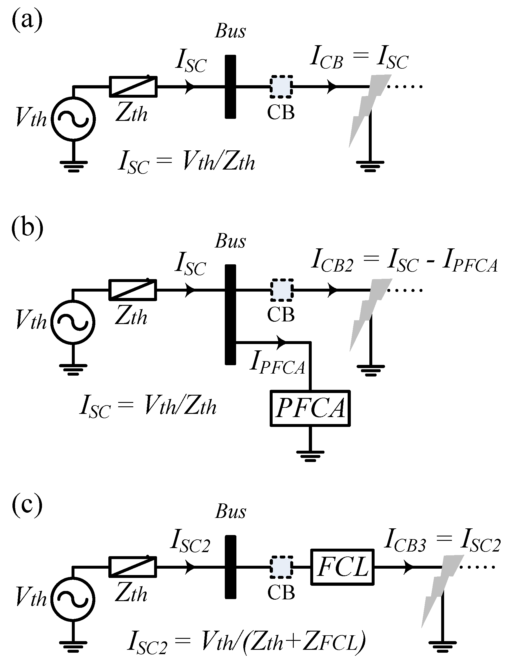
Figure 1a shows a simplified grid power distribution system composed of an equivalent voltage source and impedance (
Vth,
Zth) and a CB during a short circuit located near the busbar. The objective is to reduce the SCC amplitude through the CB. To deal with this problem, a PFCA is connected in parallel to the bus (
Figure 1b). Therefore, the short-circuit current is given by the following:
During the PFCA operation (
Figure 1b), the amplitude of the system SCC,
ISC (1), is not modified; however, the current through the CB (
ICB2) is attenuated by the current absorbed by the PFCA, as indicated in Equation (2):
Although the short-circuit current is imposed by the power system, the PFCA can absorb current from the busbar, diverting part of the power system current to the PFCA, resulting in the reduction of the CB current. For comparison, the series FCL solution is shown in
Figure 1c.
The same principle of attenuation of the PFCA can be expanded for a busbar with multiples branches, as the one shown in
Figure 2. In this case, the proposed fault current attenuator is capable of reducing the SCC in all CBs connected in each branch. In order to demonstrate the attenuation effectiveness in all CBs, the fault located in two different parts of the bus bar is analyzed (see
Figure 2):
When the faults
F1 and
F2 occur, the currents in the
j-th branch, in any one of the three phases (phase
x), are related by Equation (3):
where
ix,j,F2 is the current by branch
j in a
F2 fault, phase x;
iF1 is the fault current in the bar in a
F1 fault, phase x; and
ix,j,F1 is the current through the
j-th branch in a
F1 fault, phase
x.
The fault current
iF1 in the bar is composed of the contributions of the n branches, as indicated in Equation (4):
When a
j-th branch is connected to a passive load, there is no contribution to the SCC in the bar, that is,
ix,j,F1 is zero and, according to Equation (3), the current
ix,j,F2 would be equivalent to the fault current in the bar
iF1. In general, the greatest requirement for a
j-th CB occurs for the fault
F2 if the relation defined in Equation (5) is satisfied:
The condition in Equation (5) is frequent in bars with a high number of branches that contribute to the SCC and have a SCC level of tens of kilo-amperes.
Therefore, simultaneous overcurrents could exceed the capacity of several CBs of the same busbar. Note that the CB is the main component of a bay, which is also composed of disconnectors and current transformers, whose SCC capacity could also be exceeded.
The operation principle of the proposed PFCA is explained with the example shown in
Figure 3, where the operation of a specific CB is described. This example can be extended to all the CBs of the bar.
Figure 3a shows the SCC distribution through the different CBs when a fault occurs in branch 4 (phase a). This fault produces the highest demand for CB4. To reduce the current that circulates through CB4, which is equal to 40 kA, the proposed current attenuator scheme is connected in parallel to the bar, as shown in
Figure 3b (the PFCA is represented by a controlled current source).
The current absorbed by the PFCA is provided from the different branches that are connected to the bar. During the fault, branches 1 to 3 can be grouped and represented by the Thevenin equivalent circuit, and branch 4 by a short circuit. By analyzing this circuit (which is similar to
Figure 1b), it can be concluded that the current of 15 kA absorbed by the PFCA from the bus comes only from branch 4 (due to the fault, this branch has zero impedance). That is, one part of the SCC is diverted from the busbar to the PFCA. Therefore, the current through the CB4 is reduced from 40 kA to 25 kA. Even if the fault occurs in another branch, the PFCA operates in the same way, ensuring that the maximum current requirement in each CB of the busbar is reduced.
As explained in
Section 3, the proposed controlled current source was implemented with single-phase full-bridge inverters, connected in cascade, and in parallel to the busbar.
3. The Proposed PFCA Scheme
The active short-circuit current attenuator proposed in this paper was implemented with single-phase pulse-width modulation (PWM) H-bridge voltage source inverters using a cascade connection, as shown in
Figure 4. The number of inverters connected in cascade in each phase depends on the power system’s rated voltage and the inverter’s rated voltage.
3.1. Current Fault Detection Scheme
The detection of the short-circuit currents was carried out through the overshoot of a given current threshold
ipk. This process had to be fast enough (less than 3 ms) to compensate for the first peak of the fault current (~25% of the cycle, i.e., 5 ms). The activation of the current attenuation was supervised in each phase of the PFCA, according to Equation (6), where any
j-th branch of the n branches could activate the power converter in its respective phase:
Once the short circuit was cleared, the current flowing through the branch
j-th went to zero, and the bus voltage recovered its rated value. The PFCA stopped its operation once the bus voltage reached a predefined value
vpk:
For the ON/OFF detection scheme, a slew rate limiter was implemented with a low-pass filter (8). The cutoff frequency was adjusted to 5 times the frequency of the fundamental component of the grid to avoid the inverter over-modulation during the first cycle of current attenuation due to the delay in the detection fault:
3.2. Relevant Characteristics of the PFCA Current Control Scheme
The current control scheme must be able to fulfill the following requirements:
Must operate when the bus voltage is almost zero.
Must compensate the SCC in less than ¼ of a cycle (5 ms).
Must be independent of the location and type of short-circuit fault.
Must be independent in each phase.
The current references in each phase change during the compensation interval.
Under normal operating conditions, each single-phase power converter must be connected and synchronized with the power distribution system, keeping the dc bus voltage at its rated value.
Since the voltages of the bar can decrease to values close to zero during a short circuit, a voltage-oriented dq0 synchronous reference frame controller cannot be used. Therefore, an abc reference frame controller with an open-loop part was selected, since the current reference signal presents a transient behavior and a minimum phase shift is desired in the resulting compensation current. As shown, the use of this controller is a simple and effective solution that fulfills the compensation requirements of the proposed system.
3.3. Current Reference Generator
The current absorbed by the PFCA was subtracted from the current that circulated through the CB during a fault. In order to achieve an effective reduction of the SCC, the current absorbed by the PFCA had to have minimum phase shift error, and the same shape of the fault current.
To generate the appropriate current reference of the PFCA, represented by the controlled current source,
ix,Com, the faulted branch and phase had to be identified (
Figure 5). According to Equations (3) and (4), current
ix,j is the greatest among all the branches, since it is the sum of the other currents of the bar. Therefore, the faulted branch was identified as the maximum instantaneous current
ix,j among all the branches of the bar in each
x phase.
In this way, during the fault, the reference
ix,Com* (9) in the phase
x can be calculated as a percentage of the value of the
ix,j current (
rCom) that flows through the faulted
j-th branch:
The value of rCom depends on the percentage value required to reduce the amplitude of the SCC in all the CBs of the bus bar. The selection of rCom must allow the reduction of the maximum fault current to a value that does not compromise the safety operation of all CBs of the busbar.
3.4. Current Control Strategy
During the fault, the proposed PFCA had to track the reference
ix,Com* (9) as fast as possible and with minimum phase error. To deal with this important requirement, the current control loop had an open-loop part implemented using the activation signal (6), the reference current (9), and the measurement of the busbar voltage. In order to deal with possible modeling errors and reduce their effect, a feedback term using a proportional controller in the current loop was added. The controller output waveform corresponded to the voltage reference used as modulating signal in the voltage source inverter. The block diagram of the proposed current control scheme is shown in
Figure 6.
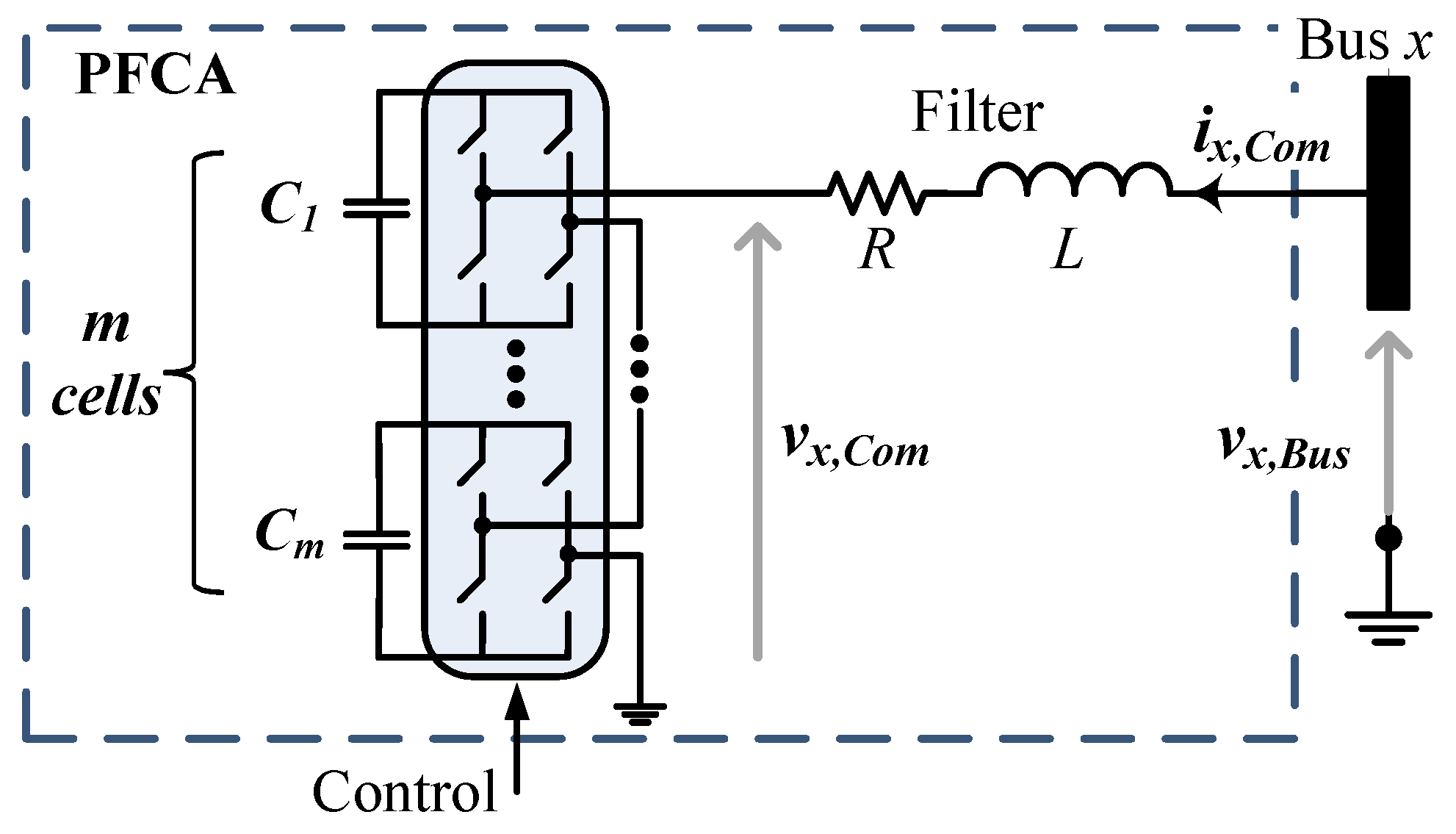
The proposed open-loop control scheme (
Figure 6) was based on the average model of the voltage source inverter and on the equivalent circuit shown in
Figure 4. In order to generate the current
ix,Com, the voltage of the
x phase of the power converter had to be adjusted to Equation (10):
where
vx,Com is the voltage at the converter terminals,
ix,Com is the current to be absorbed from the network, and
vx,Bus is the voltage measured in the busbar where the PFCA is connected.
The transfer function between
vx,Com and
ix,Com is as follows:
where
vx,Bus is considered as a disturbance. Note that the minus sign in Equation (11) is due to the reference adopted for
ix,Com (
Figure 4).
The voltage reference used by the modulator
vx,Com* (12) can be computed using the reference value
ix,Com*:
Since the inverse of transfer function (11) is not a proper transfer function and uses the derivative of the current reference, a first order low-pass filter (13) must be included. Therefore, the open-loop action is achievable and mitigates the effect of noise in the measured signal. The cutoff frequency is adjusted considering that the main noise source is the current ripple due to the inverter PWM operation. In this work, the cutoff frequency was adjusted to 10 times the frequency of the fundamental component of the grid. The use of the low-pass filter (13) did not affect the required fast tracking of the current reference signal:
Thus, the open loop is composed of the following:
Finally, to mitigate the model errors (e.g., in
R and
L parameters), a proportional feedback controller is added in (15), as shown in
Figure 6, that combines the open-loop and feedback parts:
It should be noted that to measure the current and the voltage in the bar, the existing current and voltage transformers of the protection systems can be used.
4. Simulated Results
The proposed PFCA was tested by simulation in an industrial power distribution system. In industrial power distribution systems, single-phase short-circuit currents are limited with the connection of a resistance between the neutral point (transformers and/or generators) and the ground. For this reason, three-phase faults were considered, since they generate the largest short-circuit currents and allow the performance of the PFCA to be evaluated during the operation with system voltages close to zero in all phases.
The attenuation effectiveness of the proposed PFCA was evaluated by simulation (MATLAB-Simulink, version R2019b) in a pulp plant distribution system with co-generation. The medium voltage simplified power distribution system is shown in
Figure 7. The symmetrical RMS three-phase short-circuit current (
Ik”) in 13.2 kV is 53 kA, and the rated capacity of the CBs is 50 kA.
The three-phase fault was considered at the load L1 terminals (
Figure 7). The fault was cleared by the protection system after 100 ms, a typical short-circuit clearance time for faults near busbar using three-cycle CBs.
Figure 8 shows the simulated current and voltage waveforms associated with the three-phase fault in L1 without the PFCA. Phase a presents the highest current peak through the CB of load L1.
4.1. Rated Values and Compensation Adjustment of the PFCA
The PFCA was implemented with three single-phase PWM voltage source inverters, each one using three H-bridge inverters connected in cascade (
Figure 9). Each H-bridge inverter used IGCT devices [
26], ABB’s model 5SHY 42L6500 with a maximum RMS on-state current of 2030 A (~2 kA) with a rated DC voltage of 4 kV. The rated dc voltage in each H-bridge inverter was adjusted to the maximum value of the phase-ground voltage, that is:
Each bridge used a 22 mF capacitor in the dc bus. The 22 mF capacitor was implemented with 11 film capacitors of 4 kV, 400 Arms, 2.08 mF, part number DKTFM4*#I2087 [
27].
In the case of the voltage source inverter’s output filter, an inductance of 7% was considered. This is a typical value for a transformer impedance. The reactor could be of the air-core type. Considering 2 kA rated current, this results in an inductance of 0.85 mH in series with a resistance of 2.7 mΩ (assuming a quality factor
X/R of 100, typical value for air-core reactors [
28]) in each phase. For the activation and deactivation scheme,
ipk = 25 kA and
kpk = 0.3 was assumed, respectively. The commutation frequency was adjusted to 1 kHz.
In summary, the design characteristics and associated rated values of each of the three inverters per phase of the PFCA are shown in
Table 1.
Using three H-bridge inverters and unipolar modulation, an equivalent switching frequency of 6 kHz was obtained, which was fast enough to compensate for the first peak of the SCC. Considering a first peak of current at 5 ms (¼ of a cycle in 50 Hz) and a fault detection at 3 ms, 12 commutations in the converter semiconductors were produced before the current reached the first peak.
Simulated results show that the three-phase fault, with a duration of 100 ms, required CBs with a symmetrical (
Ik”) current of 53 kA without compensation. The objective was that the PFCA reduced this value by 15%, reducing the current to tolerable levels (< 50 kA). Thus, the value of
rCom (9) was adjusted using Equation (17):
where
dCom is 0.15, the percentage (15%) by which the three-phase fault current is required to decrease.
The proportional gain
kp of the feedback controller (15) was adjusted in −2. Note that the minus sign is due to the reference adopted for
ix,Com (
Figure 4).
4.2. Fault Current Attenuation Results
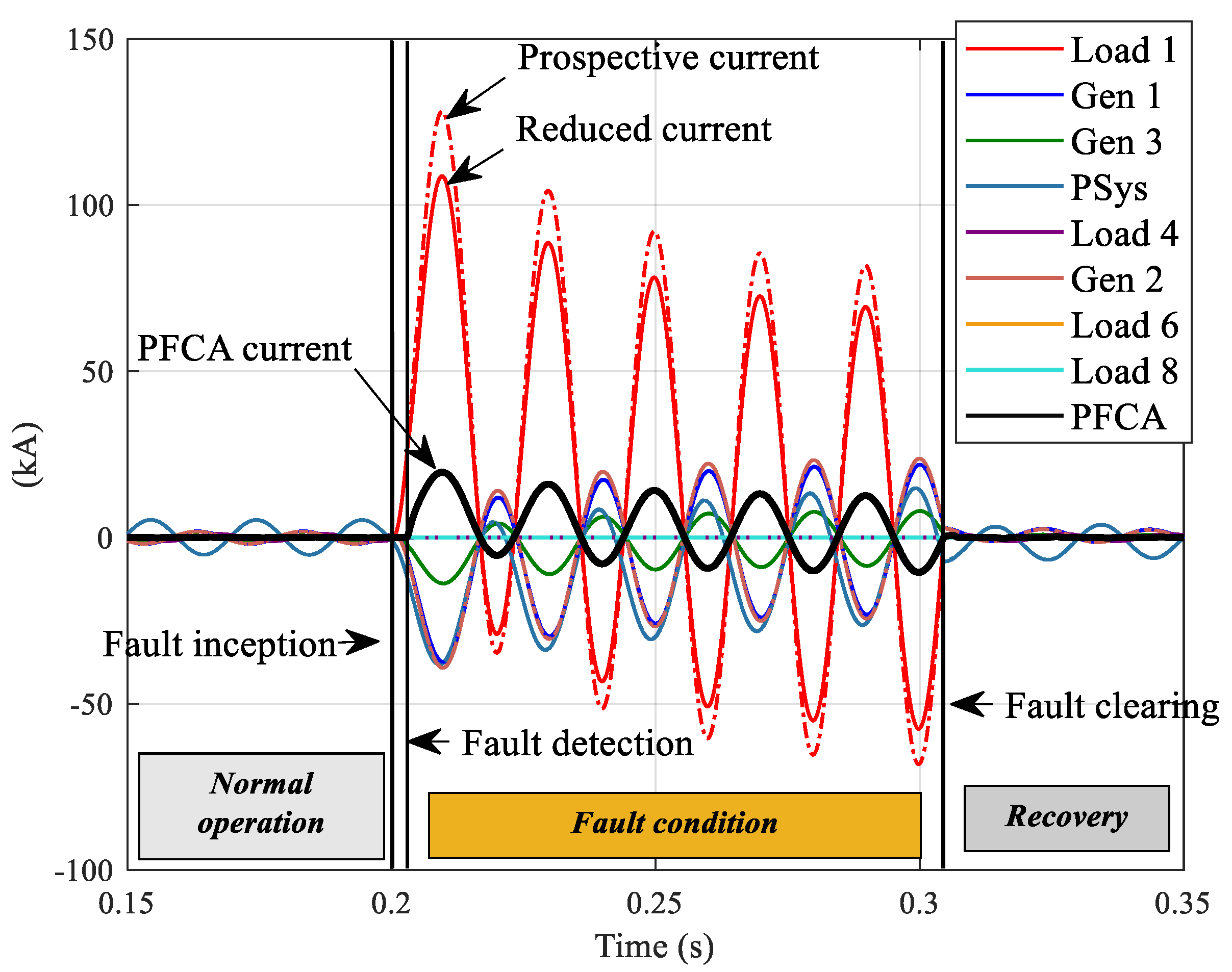
Figure 10 shows the currents (phase a) of each CB with and without the PFCA during a three-phase fault. The detection of the fault was performed after 3 ms of initiating the fault. The reduction of the fault current was very similar to the current absorbed by the PFCA. This indicates that the use of the rated capacity of the converter is optimal, since a negligible part of that current is leaked through other branches. For example, the PFCA absorbed a peak current of 19.7 kA, reducing the first peak of current through the CB by 19.5 kA (99%).
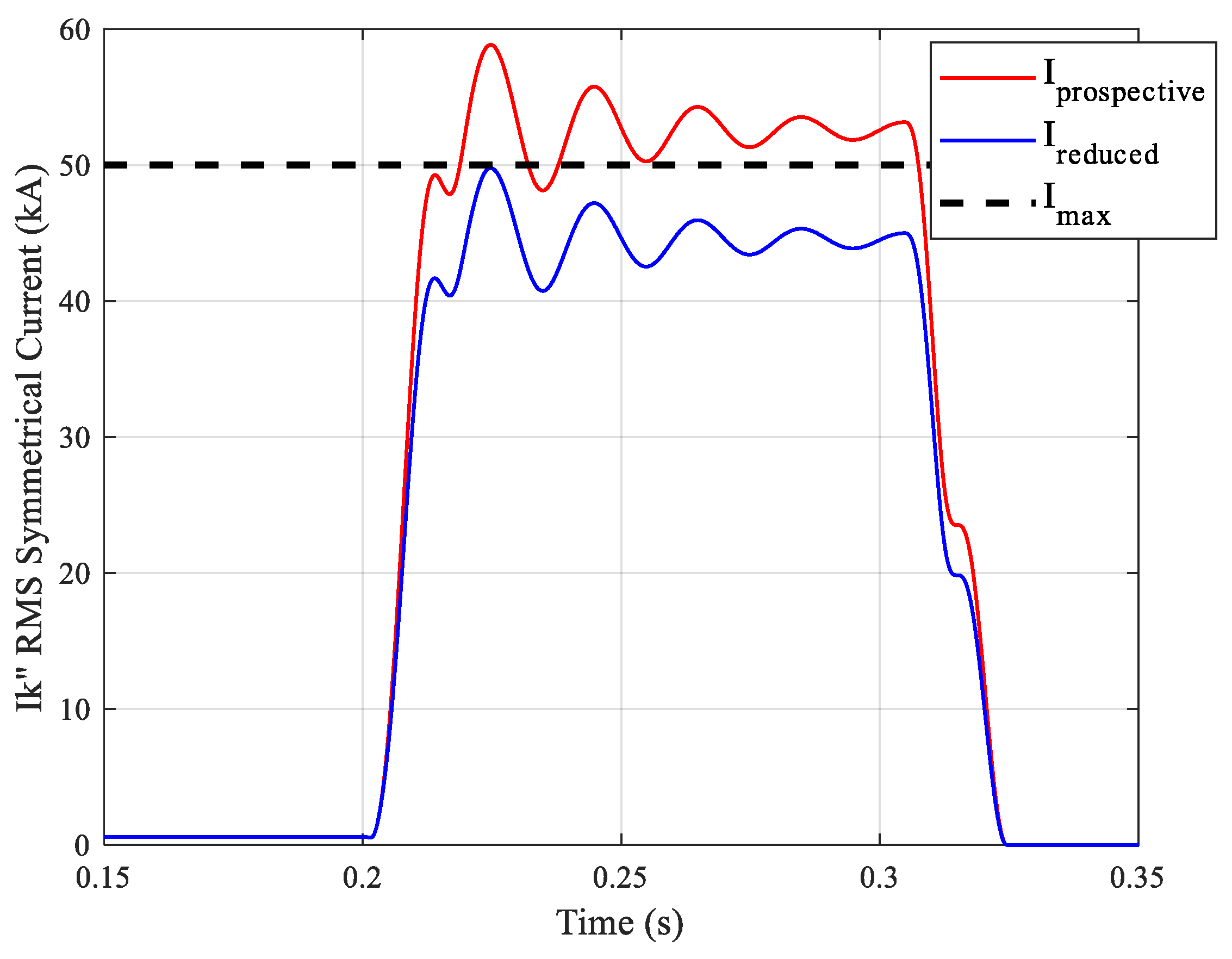
To compare the fault current with the capacity of the CB, the symmetrical SCC value was used. This value corresponds to the RMS value of the AC component of the fault current [
29]. The result is shown in
Figure 11, where the symmetrical SCC was reduced by 15%, from 53 kA to 45 kA, which is an acceptable level for the substation equipment (50 kA).
4.3. Evaluation of the PFCA Operation
In the previous section, the time response and compensation effectiveness of the proposed scheme was shown. However, it was necessary to analyze the implementation feasibility of the proposed scheme. In this regard, both currents and voltages to be handled by the power converter had to be analyzed. For this application, high currents are required during the short duration of the fault. Thus, the analysis focused on the transient capacity of the converter semiconductors. The maximum voltage was imposed by the system’s rated voltage, although during fault conditions, a much lower voltage was required.
Figure 12a shows the instantaneous and RMS current that the PFCA must deliver. At the beginning of the fault, there was a peak current of 19.7 kA, with an average RMS current of 8.7 kA during the 100 ms that the fault remained. This transient requirement allows the demand over the rated current of the semiconductor devices to relax, thus using their transient capacity during the fault. For example, the IGCT 5SHY 42L6500 [
26] has a maximum RMS on-state current of 2030 A, supporting transient currents of 40 kA during 3 ms, and 17 kA during 30 ms.
Figure 12b shows the limiting load integral
I2t supported by the semiconductors during the fault. Since the
I2t values were not indicated by the manufacturer for times greater than 30 ms, a new point at 50 ms was extrapolated based on the
I2t curve, maintaining this value as a constant up to 100 ms (worst case condition when considering more time for power dissipation). This implies a safety factor. The I
2t value at 50 ms (4.8 × 10
6 A
2s) was extrapolated based on the
I2t vs. time curve provided by the manufacturer, which presents a linear relationship in a semi-log scale (2.4 × 10
6 A
2s at 3 ms, 3.38 × 10
6 A
2s at 10 ms, and 4.34 × 10
6 A
2s at 30 ms), The results show that the maximum
I2t values defined by the manufacturer were not exceeded.
During the short circuit, the voltage in the power system dropped significantly (
Figure 13). Under this operating condition (low voltage in the power system bus), the PFCA required only 33% of its rated dc voltage value to generate the required compensation current. The harmonic analysis on the bus voltage shows that the THD is 0.52% (after 2 cycles that the fault is cleared, when the bus voltage is recovered), and the THD is 3.1% at fault time (2 cycles after the fault starts, when the bus voltage is close to zero).
The compensation of the first peak of current required more energy from the dc capacitors, reducing the dc voltage (
Figure 14). During the fault, an oscillatory behavior in the dc voltage was observed due to the circulation of high current through each single-phase converter. Moreover, the circulation of this current reduced the dc voltage average value due to the losses in the power converter’s output RL filter (
Figure 4). The ripple voltage requirement across the dc capacitors (below 20% [
27]) was not exceeded.
Moreover, since the dc voltage changed during the fault, it was necessary to modify the amplitude of the carrier signal according to the instantaneous dc voltage value to obtain a correct PWM modulation. This also allows the voltage imbalance to be regulated between the dc capacitors in each phase. Once the fault was cleared, the capacitors had to be charged from the power system through each inverter.
Figure 15 shows the reference current and the current generated by the PFCA. This figure shows that the error in the output current of the PFCA is less than 0.22 kA. Considering that the time delay in the low-pass filter (13) was 0.3 ms (6°), a 1.4% attenuation error in the short-circuit current amplitude was obtained. This result proves that the fast-tracking current of the current reference performed well using the proposed control strategy. The output current’s THD was equal to 5.8%, due to the multilevel structure, the equivalent commutation frequency that was 6 kHz, and the L filter value (7%).
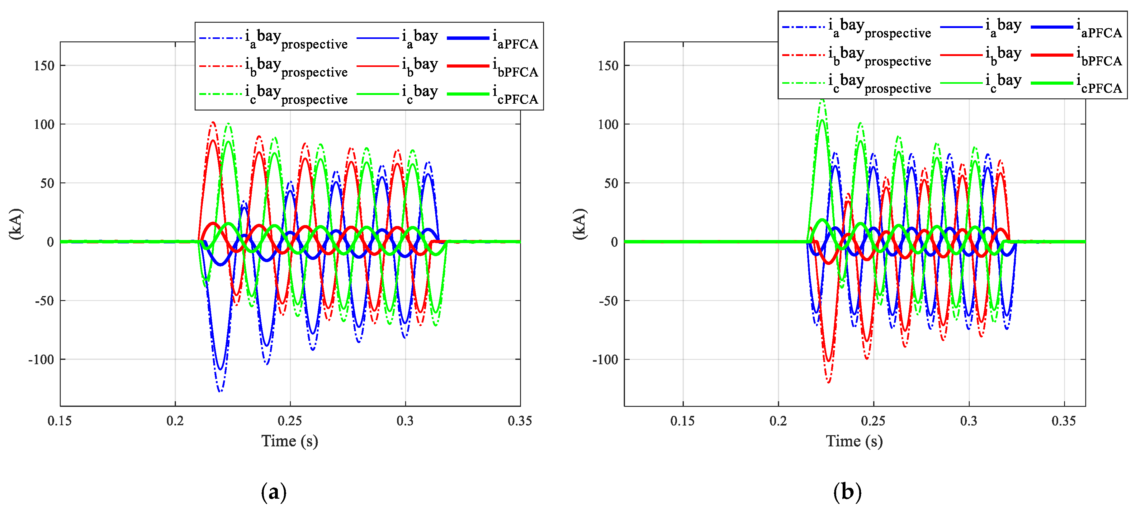
In
Figure 16a,b the operation of the PFCA for three-phase short circuits at different fault times is shown, proving the PFCA’s adaptability and compensation effectiveness. The results show that the PFCA compensation performance is independent of the fault time and the fault current waveform in each phase.


