Abstract
As a natural fluid with superior environment advantages, CO2 is used to constitute a dual transcritical system to reduce performance deterioration under high gas-cooler outlet temperature. Aiming at the system configuration, improvement potential, and optimization, the proposed system is deeply analyzed, and corresponding coupling models are presented in detail. First, the veracity of simulation models is completely verified by comparing with previous measurements. Then, the existence of the optimal intermediate temperature is validated, while the optimal values are found to increase with the augmentation in ambient and water-feed temperatures. Moreover, the negative effects of the pinch point on the heat transfer inside the gas cooler could be greatly reduced by using the dual gas cooler. Finally, a predictive correlation for optimal intermediate temperature determination with ambient and water-feed temperature as independent variables is proposed, which provides a theoretical basis for the proposed system to realize efficient control in the industrialization process.
1. Introduction
As a natural fluid with extremely superior environment and performance advantages (zero Ozone Depletion Potential (ODP), very low Global Warming Potential (GWP), non-toxic, non-flammable, pollution-free to the environment, low production cost, etc.), carbon dioxide (CO2 in this study) has come back into researchers’ views since its transcritical operating mode was proposed by Lorentzen [1,2]. In recent years, the transcritical CO2 system was further introduced into space-heating applications [3,4] due to its characteristics that can be employed to provide a hot recirculating medium at extremely high temperature [5]. In cold regions with a heating season of more than 4 months, especially in northern China, coal-fired boilers, gas-fired boilers, and even electric boilers (and coal-fired electricity in general) are still the most widely used type of space heating, which has doubtlessly brought about great environmental pollution. By contrast, air-source heat-pump heating technology is a cleaner solution since the only consumption is electric power and most of the energy source is heat energy from the atmosphere. Thus, as natural refrigeration with the ability for high-temperature water supply in a transcritical mode, the import of a transcritical CO2 system into space-cooling/heating applications suggests a revolution in the heating/cooling energy-supply fields because of the environmental friendliness and higher performance coefficient (ratio of heating capacity and power consumption).
However, the fact that the performance of the transcritical CO2 system would deteriorate sharply with the increase in the gas-cooler outlet CO2 temperature that is limited by the working medium (water in general) inlet temperature is always the biggest problem blocking its popularization within the space-heating industries. Researchers have been devoted to performance improvement studies of the transcritical CO2 system for decades.
To reduce the gas-cooler outlet temperature in the application with high water-feed temperature, the internal heat exchanger (IHX) is treated as the easiest approach at the beginning. Referring to the p–h diagram of the IHX-based cycle, the enthalpy differences in both gas cooler and evaporator are definitely increased; however, the tendency of the system coefficient of performance (COP) cannot be determined because of the reduced mass flow rate and increased compression enthalpy difference caused by the rising superheating [6]. On the other hand, the adaptability of the IHX is dependent on the operating conditions, such as gas-cooler outlet temperature, discharge pressure, and evaporating temperature [7,8,9].
Owing to the very limited effects of the IHX on the transcritical CO2 system, the flash tank/economizer and multi-compression (which are called “parallel cycles” in this article) were introduced into the transcritical cycles. Although a quite mature technology for conventional refrigeration cycles [10,11,12], the parallel cycles not only enhanced the system performance, but also improved system properties such as the reduction of discharge temperature [13]. Additionally, various research has been carried out around vapor injection techniques in transcritical cycles, and three kinds of modifications were compared [14,15,16]. Similarly, with the expander-based system, the vapor ejector benefits from energy recovery from the expanding process into the compression process [17,18]. Considering the very high-pressure difference between cooling and evaporating pressures in the transcritical cycle, the potential for energy recovery could be remarkable.
However, the problem of high gas-cooler outlet temperature was never directly improved by parallel and ejector-based technologies, and thus the system performance could not be remarkably enhanced by existing methods. Furthermore, unlike the IHX-based system [6], the parallel compression-based system [14], and the ejector-based system [19,20], which adopts no dedicated technique to improving the system performance by reducing the gas-cooler outlet CO2 temperature directly, the subcooling technology has developed considerably over recent years. Sarkar proposed a combined configuration of the transcritical CO2 system with an auxiliary thermoelectric module as the subcooler, which is sandwiched between the gas cooler and expansion valve [21], by which the optimal discharge pressure could be reduced by more than 15% while the system COP could be increased up to 20% under certain conditions. Furthermore, considering the inconvenience of the thermoelectric module, Llopis et al. proposed a similar system with a conventional vapor-compression cycle as the subcooler [22,23], by which better subcooling effects could be achieved. In addition, as the working fluid in the subcooler, several kinds of refrigerants are comprehensively compared regarding their subcooling performance, where it is found that no obvious difference in system performance occurred with a change of working refrigerants. Aiming for a similar subcooler-based transcritical CO2 system, Dai et al. studied energetic performance by using zeotropic mixture refrigerant as the working fluid in the subcooler [24], and the corresponding exergy and economic analyses were carried out in detail [25].
Additionally, the vortex tube is introduced into the transcritical CO2 system as the expansion device instead of the expander, and the benefit of the vortex tube lies not only in the transformation from isenthalpic throttling to isentropic expansion, but also in the additional heating capacity caused by the hot side of the vortex tube. Theoretical results showed that the vortex tube-based transcritical CO2 system performs significantly better over the baseline cycle [26]; however, no experimental validation could be found to support the theoretical conclusions.
However, although significant preliminary works have been done by scholars around the world, the state of the art of subcooling technology is still not the ideal solution because the working fluids of the subcoolers (named “auxiliary cycles” in this study) are hydrofluorocarbon (HFCs) in general, and especially R134a [3,4].
In this study, an innovative subcooling method is proposed, in which a dedicated transcritical CO2 system is employed to be the auxiliary subcooler. With the help of a transcritical CO2 subcooler proposed in our study, this combined system has finally, and for the first time, achieved the goal of energy-saving and environmental protection. Similar to the HFC subcooler-based systems, the auxiliary transcritical CO2 cycle is also installed between the main cycle’s gas cooler and electrical expansion valve (EEV), while the operating mechanism and corresponding dynamic response rules of the whole system might be different because the operating mode of the auxiliary cycle is transformed from the subcritical to the transcritical. In this study, the whole system (i.e., an upgraded heat-pump system) is theoretically discussed in depth and the inherent characteristics of the system are well established.
In addition, it can be inferred that there might be an optimal intermediate temperature (defined as the temperature before the main cycle’s EEV, state point 3 in Figure 1b) in the dual system with heating applications, because when the intermediate temperature changes, the performance of the main cycle and the auxiliary cycle would vary in exactly the opposite way. This study researches the response rules of the optimal intermediate temperature with the operating conditions, which provides enough theoretical basis for the proposed system to realize efficient control in the industrialization process in the future.
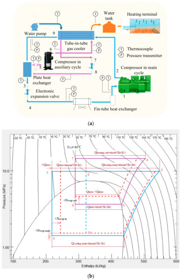
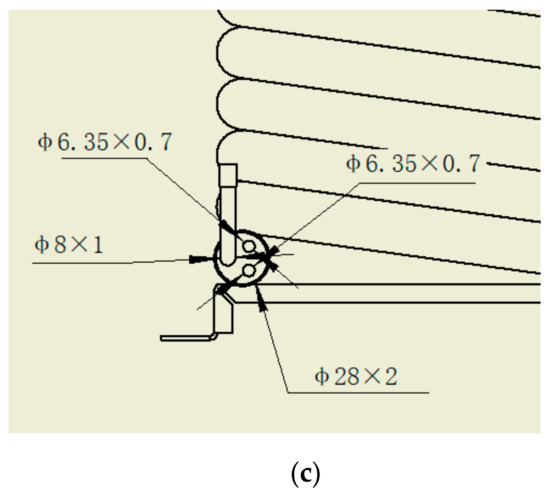
Figure 1.
(a) The sketch map of the dual CO2 system; (b) the p-h diagram of the dual CO2 system; (c) the sketch map of the dual gas cooler.
As a method for improving the performance of the transcritical CO2 system, subcooling technology has already become one of the most popular topics in both cooling and heating applications. Much significant research has been carried out regarding performance prediction, simulation procedure, and parameter optimization works of the subcooler-based system, although there still are some specific points to be mentioned in this study. First, our work is one of the few that use pure natural refrigerant (CO2) replacing HFCs and hydrocarbon (HCs) (R134a, R600a etc.) as the working fluid in the subcooler cycle, which manifested the lower GWP of our system, because R744 (CO2) GWP = 1, R600a GWP = 3, and R134a GWP = 1300. Second, in this study, the main points of the research on the dual system are the establishment and validation of the simulation models, as well as the prediction of the optimal intermediate temperature. Moreover, most content in this paper is occupied by the discussion of the effective factors seeking the optimal intermediate temperature, and a predictive correlation is finally obtained based on the operating conditions as variables.
2. System Description
2.1. System Configuration
In this study, the sketch map of the proposed dual system is clearly shown in Figure 1a and corresponding a p–h diagram could be drawn as Figure 1b. As we can see, the main cycle of the system, which is comprised of compressor, gas cooler, EEV, and evaporator, is a common transcritical cycle with an extra subcooler that is a standard plate heat exchanger. Moreover, the plate heat exchanger is not only the subcooler of the main cycle, but also the evaporator of the auxiliary cycle, which could provide both cooling capacity for the main cycle’s refrigerant after the gas cooler and heating capacity for the recirculating water in the gas cooler. It should be noted that the discharge refrigerants in both the main and auxiliary cycles are imported into the same gas cooler, which undertakes the mission of transferring the total heat capacity from auxiliary and main cycles to the recirculating water. As a tube-in-tube heat exchanger, the gas cooler adopted in this study has three inner tubes to cover all the refrigerants from both auxiliary and main compressors. Specifically, two inner tubes belong to the main cycle via a three-way connector, and another inner tube is connected to the auxiliary compressor. Furthermore (see Figure 1a), counter-current heat transfer could be achieved inside the gas cooler because the entrances of the CO2 flows from both auxiliary and main cycles are located on the right side of the gas cooler, where the exit of the recirculating water loop is also located. As a whole, the proposed dual CO2 system could realize the intended target: absorbing thermal energy from the ambient environment via the main cycle evaporator (i.e., a fine-tube heat exchanger) and exhausting thermal energy to the recirculating water via the dual gas cooler, which results in space-heating effects through the heating terminals during the heating season (more than 4 months in northern China). With the assistance of 6 pressure transmitters and 12 thermocouples (including the ambient temperature sensor, which does not appear in Figure 1a), all the refrigerant state points could be measured and thermodynamic research could be continued.
In addition, it should be noted that two liquid–vapor separators are installed through the suction line in both main and auxiliary cycles, which always maintain that the suction state points of the two sub-cycles comprise saturated refrigerant vapor if the refrigerant charge amounts are appropriate. The sketch map of the dual gas cooler is shown in Figure 1c for better understanding of its configuration and the water circulation channel inside it.
2.2. Theoretical Analysis
The corresponding p–h diagram of the proposed dual system can be found in Figure 1b, in which the blue loop (1-2-9-3-4-10-1) and purple loop (5-6-7-8-5) represent the main cycle and auxiliary cycle, respectively. Thanks to the dedicated subcooler, the refrigerant CO2 at the main cycle’s gas-cooler outlet could be further cooled down from state point 9 to state point 3. Having been subcooled, the CO2 temperature before the main cycle’s EEV could be reduced to lower than the water-feed temperature (i.e., 40 °C in Figure 1b), which causes a lower discharge pressure in the main cycle. Comparatively, the discharge pressure of the auxiliary cycle must be much higher than that of the main cycle because the CO2 temperature before the auxiliary cycle’s EEV should be no less than the water-feed temperature. Moreover, in general, the discharge temperature increases with increase in discharge pressure. However, due to higher evaporating pressure and lower pressure ratio in this cycle, the discharge temperature of the auxiliary cycle might be remarkably lower than that of the main cycle (see Figure 1b) although the auxiliary cycle’s discharge pressure is far higher. As a coupled system, the displacement ratio of the two compressors is strictly constrained by the heating capacity coupling condition: the cooling capacity of the auxiliary cycle should be identical to the subcooling capacity of the main cycle, i.e., the regulation of the intermediate temperature (achieved by regulating the auxiliary compressor speed) can be only realized by adjusting the compressor displacement ratio or frequency ratio.
Furthermore, any manual regulation of the intermediate temperature will cause a series of moves inside the dual system. For instance, because the evaporating temperature of the auxiliary cycle constrains the limitation of the intermediate temperature, the increase in the CO2 temperature before the main cycle’s EEV and the increase in the auxiliary cycle’s evaporating pressure would definitely occur in pairs, as the red dashed lines show in Figure 1b. The variation mentioned above causes changes to the internal heat-transfer capacity () and the main cycle’s quality after the EEV () in Figure 1b.
In addition, the increase in intermediate temperature (i.e., the right shift of state point 3 in Figure 1b) will always cause a reduction to the cooling capacity in both the main and auxiliary cycles. On the one hand, the decline of the enthalpy difference along the main cycle’s evaporator corresponds to the decline in the main cycle’s cooling capacity; on the other hand, the decrease of the subcooling capacity represents a decrease in the auxiliary cycle’s cooling capacity. What is significant is that the main cycle’s evaporating pressure is supposed to increase slightly with the rise of the intermediate temperature because, considering that state point 1 is always located at the saturated line, the main cycle’s cooling capacity can be reduced only by declining the heat-transfer temperature difference between the evaporating and the ambient temperatures.
From Figure 1b, it could be deduced that the increase in the intermediate temperature improves the performance of the auxiliary cycle (due to the remarkable increase in evaporating pressure and decline in compressor pressure ratio) but deteriorate the main cycle (due to the significant decrease in both heating and cooling capacities), which creates the necessity to seek and assess the optimal value of the intermediate temperature.
First, it should be noted that all the cooling capacity assigned to the dual system is completely undertaken by the main cycle, and the only mission assigned to the auxiliary cycle is that of transferring the subcooling capacity from the main cycle to the recirculating water by consuming compressor power, i.e., considering the subcooling capacity provided by the auxiliary cycle as a part of the heating capacity of the main cycle which should be performed at the operating condition with low water-feed temperature, the auxiliary cycle would be treated as an electric heating module that transfers electric power into heat for the recirculation of water from the point of view of energy conservation.
Additionally, another advantage of using the dual-combined gas cooler is that the influence of the pinch point on the heat transfer might be considerably weakened, because the temperature distributions of the two refrigerant loops inside the gas cooler will not overlap. It should be noted that considering the real cases in practice, the name “pinch point” is used for indicating a position inside the heat exchanger where only tiny temperature differences could be observed, i.e., the name “pinch point” represents a position with the lowest temperature difference along the whole gas cooler in this study.
3. Mathematical Model
3.1. The Seeking Process of Optimal Discharge Pressures
In the process of mathematical model establishment, the most important thing is the determination of discharge pressures in both sub-cycles, since the two sub-cycles are both transcritical cycles with optimum performance under optimal discharge pressure. The flow chart of the dual optimal discharge pressure-seeking process is shown in Figure 2a. The idea of the exhaust algorithm (simulating every possible discharge pressure of both sub-cycles with 0.05 MPa in the changing step) is adopted in this study, through which a two-dimensional grid could be built with the discharge pressures as the independent variables. Upon this two-dimensional grid, the maximum COP (the ratio of total heating capacity and power consumption) can be selected, and the corresponding discharge pressures of the sub-cycles can be found.
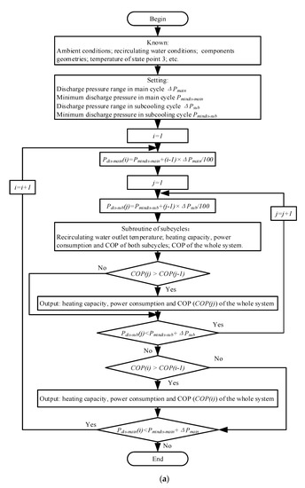
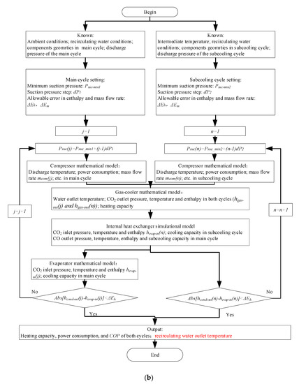
Figure 2.
(a) The process of the dual optimal discharge pressure-seeking; (b) the process of the dual system’s thermodynamic simulation.
3.2. The Simulation Process of the Dual System’s Thermodynamic Performance
After determining the optimal discharge pressures, the simulation process of the dual system can be started, and the simulation flow chart is shown in Figure 2b. Based on the given working conditions and the assumed suction pressure, the iterative computations can be carried out gradually and the correct suction pressure can be worked out. It can be seen that, except for the gas-cooler model and internal heat exchanger model, the simulation processes of the auxiliary and main sub-cycles are completely independent. The mathematical models of the components adopted in this study are basically drawn from open literature on the CO2 compression process [27], the heat transfer in the internal heat exchanger [3,28], the supercritical CO2 cooling process in the gas cooler [29,30], the subcritical CO2 evaporating process [31], and the heat-transfer correlations of air and water sides [32]. The main equations and correlations of those components’ simulation models are summarized in Table 1. In the whole simulation process, because our creative works are embodied not in the mathematical models of the components but in the coupling model of the overall system, the simulation flow charts are clearly shown in this section.

Table 1.
The main equations and correlations of the component models.
It should be noted that some realistic factors, such as the pressure drops caused by components, are considered not in Figure 2a but in Figure 2b, which makes a slight difference occur between the optimal discharge pressures sought from Figure 2a and the real ones in Figure 2b. However, after analyzing the simulated and tested data, a conclusion could be drawn that a deviation of ±0.2MPa in discharge pressures (of both auxiliary and main cycles) would only cause no more than 1% in COP fluctuation, which shows the dependability of the dual optimal discharge pressure-seeking process.
4. Results Discussion
4.1. The Verification of the Simulation Model
In this study, the heating capacities of whole or sub-systems are calculated by multiplying the enthalpy differences and mass flow rates of the refrigerants in the simulation models, respectively. Similarly, the power consumptions in the simulation processes are also obtained as a product of enthalpy differences and mass flow rates, while the fan power was definitely considered. Referring to the measured values based on plentiful tests, the fan power in the simulation was set as a constant, 0.2 kW, for all the simulation conditions because no frequency conversion control strategy was adopted for this fan. However, some experimental data from our pre-works were referred to in this section to validate the veracity of the mathematical model, as shown below. In the experimental measurements, the total heating capacity of the whole system was calculated from the water side (by multiplying the water temperature difference, specific heat of water, and its mass flow rate), because all the heating capacity occurred inside the dual gas cooler. Additionally, the total power consumption in the experimental tests was collected by a power meter; the power consumption of the compressors (main and auxiliary cycles) and the fan were considered.
To validate the mathematical model and coupling model presented above, a prototype of the dual transcritical CO2 system with a dedicated transcritical CO2 subcooler is carefully built, and plentiful measurements are carried out in the enthalpy difference laboratory. The detailed parameters of the prototype can be found in our previous publication [33], and the intermediate temperature can be achieved by regulating the auxiliary compressor speed. After comparing the simulation results with our previous tests, the veracity of the simulation models can be verified, which gives us the convenience to carry on the discussion that is shown below based only on the simulation results. The relative errors between the tested data and simulation results are no more than 5% across the operating range, and the comparison is shown in Figure 3. The working condition is −12°C in ambient temperature, and 50 °C/70 °C in water-feed/supply temperature, respectively.
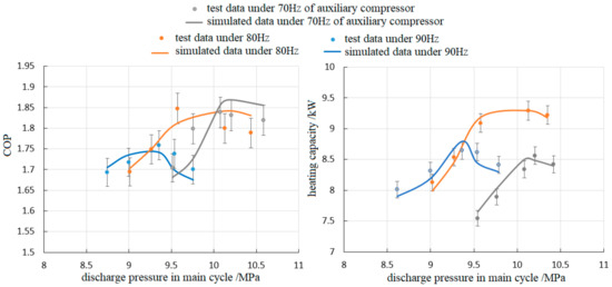
Figure 3.
The comparison between simulation and experiment results.
4.2. Discussion about the Intermediate Temperature
At different operating conditions (water-feed temperature, water-supply temperature, and ambient temperature included) and different intermediate temperature, the proposed dual system is supposed to perform at various COP, as shown in Figure 4. Commonly, the system COP increases significantly with the increase in ambient temperature and the decline of water-feed temperature, because higher ambient temperature and lower water-feed temperature correspond to lower compressor pressure ratio and higher heating/cooling capacities, which benefits system performance. What is more important is that as a coupled system that is similar to the cascade cycle, the system COP of the proposed dual prototype shows greater relativity to the intermediate temperature, as shown in every diagram from Figure 4, in which the system COP increases first, and then declines with intermediate temperature rising, which is good proof of the existence of an optimal intermediate temperature.
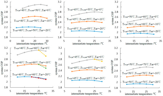
Figure 4.
The system coefficient of performance (COP) versus the intermediate temperature.
It should be noted that all theoretical simulations under the 18 operation conditions were carried out based on the same geometry configurations of the components, as shown in Table 2. For instance, the heat-transfer capabilities of the heat exchangers (gas cooler, evaporator, and internal heat exchanger) selected in the tests are basically enough for most cases among the test range, which results in a very close relationship between the CO2 gas-cooler outlet temperatures of both main and auxiliary cycles, and the water-feed temperature. The theoretical data shown by the full lines in Figure 4, Figure 7 and Figure 9 are simulated results considering the discharge pressure optimizations in both main and auxiliary cycles. However, the observed optimal discharge pressures of one or both sub-cycles are not high enough to bring about the expected discharge temperatures in some cases, which causes a deficiency of the heat-transfer temperature difference between the CO2 flows and the recirculating water, if the water-supply temperature is high. Because of the low temperature difference following the deficiency of the heating capacity, the CO2 gas-cooler outlet temperature could not be completely cooled down to the level of the water-feed temperature any further. It is conceivable that the settled discharge pressures should be further increased to overcome the deterioration caused by the much higher gas-cooler outlet temperatures, which brings about the irreversible decline of the overall system performance, as shown by the dashed lines in Figure 4. In contrast to the full lines that represent the ideal cases, these situations are defined by “real cases” in this study to show that those cases represented by the dashed lines are real results considering the fixed heat exchanger in practice. The above-mentioned deterioration would be sharper with the decline in water-feed temperature, the rise in ambient temperature, and the increase in water-supply temperature, because lower water-feed temperature corresponds to lower optimal discharge pressures, and higher ambient temperature represents lower compression ratio, which would definitely cause a decline in discharge temperature. Moreover, higher water-supply temperature is adverse for the establishment of temperature difference inside the gas cooler.
Table 2.
The main geometries of the main components.
The observed optimal intermediate temperature and corresponding COP (the maximum system COP) under various operating conditions are clearly shown in Figure 5a,b. It can be easily seen that the optimal intermediate temperature rises remarkably with the increase in ambient temperature and water-feed temperature. The optimal intermediate temperature increases by 8.48 °C on average with the ambient temperature increasing from −20 °C to 0 °C, while it increases by 2.86 °C on average with the water-feed temperature rising from 40 °C to 50 °C, i.e., the effect of ambient temperature is more obvious. On one hand (see loop 1-2-9-3-4-10-1 from Figure 1b) the higher the ambient temperature after system performance, the smaller the subcooling capacity that the main cycle needs to overcome the deficient heating capacity. The main cycle’s discharge pressure would rise with an increase in ambient temperature, and the left shift of state point 9 would occur upon enough heat transfer inside the gas cooler, which causes the decline of the subcooling requirement. On the other hand, state point 9 would move to the right with an increase in water-feed temperature, which causes a sharp increase in subcooling requirement if the state point 3 keeps still. A superfluous auxiliary cycle would basically go against the target of improving the system performance, because of the redundant power dissipation caused by the auxiliary cycle and the unchanged system cooling capacity.
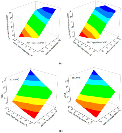
Figure 5.
(a) The optimal intermediate temperature versus the operating conditions (water-feed temperature and ambient temperature); (b) the maximum system COP versus the operating conditions (water-feed temperature and ambient temperature).
The optimization processes and results of the intermediate temperature and corresponding system COP are discussed as mentioned above. From a more fundamental point of view, the maximization of the system performance is generally based on the optimizations of the two sub-cycles. For instance, the thermodynamic parameters of the auxiliary cycle, main cycle, and whole system under 50 °C/70 °C in water-feed/supply temperatures are clearly displayed in Figure 6. Upon the unchanged compressor displacement of the main cycle, the decline of the auxiliary cycle’s refrigerant mass flow rate would decrease with an increase in the intermediate temperature because of the decreased subcooling requirement after the decreased compressor displacement of the auxiliary cycle. As a result, the power dissipation, heating capacity, and cooling capacity of the auxiliary cycle decrease with increasing intermediate temperature, because the impacts of the mass flow rate decrease would be much more noticeable than that of the operating conditions change. However, due to rising evaporating temperature, it is always observable that COP of the auxiliary cycle improves dramatically with the increase in intermediate temperature, as shown in Figure 6.
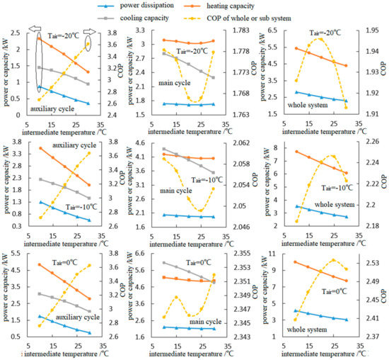
Figure 6.
The thermodynamic parameters of the auxiliary cycle, main cycle and whole system under 50 °C/70 °C in water-feed/supply temperatures.
In addition, the slightly increased evaporating temperature of the main cycle (as explained in Figure 1b) causes the refrigerant mass flow rate to elevate slightly, while the sought-after optimal discharge pressure of the main cycle declines generally with the intermediate temperature increasing, which causes an almost unchanged heating capacity and power dissipation of the main cycle. The declines in the heating capacity and power dissipation of the main cycle are no more than 5%, which jointly brings about the sub-cycle’s COP changes by less than 1%, and it is difficult to describe its changing trend qualitatively. By contrast, the cooling capacity of the main cycle goes down remarkably with the increase in intermediate temperature, because higher refrigerant temperature before the EEV gradually increases the refrigerant quality at the evaporator entrance, which significantly decreases the enthalpy difference between evaporator inlet and outlet.
As the results of the combined effects of the sub-cycles, the total heating capacity and power dissipation of the overall system decrease gradually with an increase in the intermediate temperature because the total heating capacity and power dissipation of the overall system are exactly the algebraic sums of those of the sub-cycles. Moreover, since the cooling capacity of the overall system is exactly the cooling capacity of the main cycle (the auxiliary cycle provides no cooling capacity to the ambient environment), the curves of cooling capacity are no longer shown in the diagrams of whole system. The last diagram of Figure 4 shows that the overall COP trends of increase first and then decline could be also seen in Figure 6, although the amplitude of variation are also no more than 5% under any certain operating conditions.
Similar to the conclusions from our pre-work [3], the varying intermediate temperature will significantly influence the mail cycle performance on two sides. On the one hand, the increase in intermediate temperature raises the temperature limitation of the gas-cooler outlet temperature in the main cycle; for instance, the gas-cooler outlet temperature might be risen from 15 °C to 35 °C with the intermediate temperature increasing from 10 °C to 30 °C, which doubtlessly causes the decline of the main cycle’s performance (COP especially). However, on the other hand, the point mentioned above could only be achieved based on this condition: the heat-transfer process inside the internal heat exchanger is always enough. In practice, because the auxiliary cycle’s compressor is fixed, the auxiliary cycle’s mass flow rate must be reduced remarkably with declining intermediate temperature/pressure after the declining suction density. Thus, too low a mass flow rate inside the internal heat exchanger is not good for heat transfer, which causes too low an intermediate temperature to spoil the effect of decreasing the main cycle’s gas-cooler outlet temperature. Taking the combined effects mentioned above into consideration, there is no certain trend of intermediate temperature on the main cycle’s COP, as shown in Figure 6. In addition, from Figure 6 we can see that the fluctuation of the main cycle’s COP are no more than 0.6% in all the operating conditions, so to the authors’ knowledge, it makes no sense to summarize the observed trends of the main cycle’s COP shown in Figure 6.
As mentioned in the last paragraph, the refrigerant mass flow rate of the main cycle would be increased slightly with an increase in the intermediate temperature because of the rising evaporating pressure, while the changing trends of the refrigerant mass flow rate in the auxiliary cycle would be more complicated. On the one hand, the reduced subcooling requirement highly decreases the compressor displacement of the auxiliary cycle with the increase in the intermediate temperature. However, on the other hand, the increased evaporating pressure of the auxiliary cycle greatly increases suction density. As a combined result, the refrigerant mass flow rate in the auxiliary cycle has no fixed changing trend within the selected range.
As for the real cases in Figure 7, the refrigerant mass flow rate of the main cycle is quite close, while that of the auxiliary cycle is obviously higher than that of ideal cases. Because the refrigerant temperature before the auxiliary EEV is much higher and the refrigerant quality at the evaporator entrance is much bigger than that of the ideal case, the decreasing enthalpy difference between the auxiliary evaporator inlet and outlet causes increasing mass flow rates in the real cases.
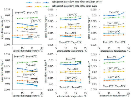
Figure 7.
The refrigerant mass flow rates in both auxiliary and main cycles versus the intermediate temperature.
As mentioned above, the refrigerant mass flow rate in the main cycle would increase gradually with an increase in the intermediate temperature, because the evaporating pressure of the main cycle increases gradually in all the simulation range, as shown in Figure 8. As explained in Figure 1b, the refrigerant temperature before the main EEV thereafter the quality at the main evaporator entrance increase (shift to the right in p-h diagram) with the augment in intermediate temperature, resulting in the decline of the enthalpy difference between main evaporator inlet and outlet. Thus, the heat exchange capacity of the evaporator is reduced while the geometry and heat transfer coefficient remain almost constant, which leads to an increase in evaporation temperature and decrease of the heat transfer temperature difference in the main evaporator.
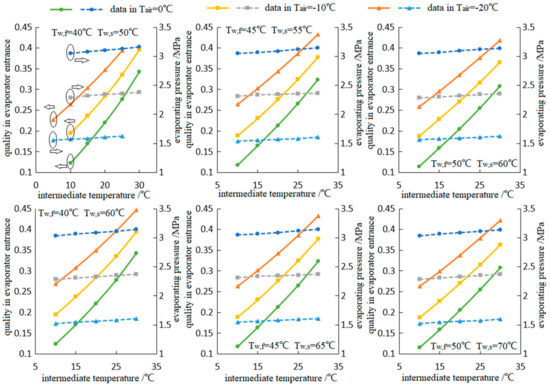
Figure 8.
The evaporator entrance quality and evaporating pressure in main cycle versus the intermediate temperature.
Unlike the trends that show the main evaporating temperature rising stepwise with the increase in ambient temperature, the refrigerant quality at the main evaporator inlet goes against the ambient temperature, because in the two-phase region of CO2 refrigerant the lower the refrigerant temperature is after the main EEV, the further the refrigerant state point deviates from the saturated liquid line.
In addition, it could be observed that the refrigerant quality at the main evaporator inlet declines slightly with the water-feed temperature increasing, because higher water-feed temperature then higher intermediate temperature causes bigger refrigerant quality at the evaporator inlet and higher evaporating pressure of the main cycle. However, the water-feed and -supply temperatures have little effect on the evaporating pressure or the evaporator’s inlet quality.
Since it is an important part of the simulation process, the optimal discharge pressures in both main and auxiliary cycles should be sought before establishing the simulation model of the whole system, as shown in Figure 2a,b. The sought discharge pressures and corresponding discharge temperatures in both cycles at 40 °C/60 °C in water-feed/supply temperatures are clearly shown in Figure 9.
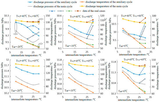
Figure 9.
The discharge pressure/temperature in both cycles versus the intermediate temperature at 40 °C/60 °C in water-feed/supply temperatures.
As shown in Figure 9, the discharge pressure and corresponding discharge temperature generally decline with increasing intermediate temperature, which is abnormal with the common sense of the standard transcritical CO2 cycle: the discharge pressure of the main cycle does not increase with the increasing refrigerant temperature before EEV, while that of the auxiliary cycle does not rise with the increase in evaporating temperature. The conclusion that the discharge pressure would increase with evaporating temperature is proposed under the premise of certain water-supply temperature or certain heat-transfer temperature differences inside the gas cooler. However, the discharge temperature of the auxiliary cycle is very free in most cases in this study, which causes a declining optimal discharge pressure with rising evaporating temperature [34]. The simulation evidence has indicated that great increase in power dissipation and little increase in heating capacity could be achieved by a further rise in the auxiliary cycle’s discharge pressure.
In the terms of the main cycle, the heating capacity and the COP of the main cycle would increase slightly with rising refrigerant temperature before EEV if the discharge pressure is set to increase. However, the declining enthalpy difference between state points 3 and 9 (see Figure 1b) then the decreasing subcooling requirement would definitely reduce the refrigerant mass flow rate in the auxiliary cycle, which causes the consequent reduction of the auxiliary cycle’s power dissipation and heating capacity. Due to better operating conditions and lower compression ratio, the sub-cycle COP of the auxiliary cycle is more than 50% higher than that of the main cycle. Thus, the losing heating capacity caused by the decreasing auxiliary cycle’s mass flow rate would be much more than the additional heating capacity achieved from the main cycle if the main cycle’s discharge pressure rises to a higher level. Above all, the result could be sought that the discharge pressures of both the auxiliary and main cycles generally go down (although several exceptions exist, see Figure 9) with rising intermediate temperature.
In addition, as for real cases, it could be found that the discharge pressure and corresponding discharge temperature are obviously higher than that of ideal cases, because the discharge pressure is supposed to increase conquering the deficiency of the heating capacity in the real cases.
Although the two-phase region of the refrigerant CO2 would never during the heat-transfer process reach inside the gas cooler of a transcritical CO2 cycle, the pinch point of the heat transfer can also be observed in many cases due to the huge increase of specific heat near the critical point [35]. As shown in Figure 10b, the curve of the water temperature displays almost a linear growth, while the cooling rate curve of the refrigerant CO2 is much more complicated with the change of the complex heat capacity variation near the critical point. It is well known that a steep rise of specific heat capacity of refrigerant CO2 could be observed nearby the critical point, which causes a slow process of temperature change to be seen during the heat-rejection process from point 1 to 3 in Figure 1b. That trend is clearly shown in Figure 10b as a blue line. By contrast, the specific heat capacity of water keeps almost constant during the heating process, which causes linear growth of the black line in Figure 10b. As a result, the temperature distribution inside the gas cooler must experience a certain process with lower temperature difference between water and CO2. Moreover, it could be found that the heating rate curve of the recirculating water would be slowed down gradually before the pinch point if the flow path geometry of the gas cooler is settled as the abscissa, because the heat-transfer temperature difference declines gradually. However, as shown in Figure 10a, the inflection points of both the cooling rate curves are located in different places, which consequently makes the heating rate curve of the recirculating water rise smoothly and the average heat-transfer temperature difference remain almost constant along the main region of the gas cooler. Through such a clever design, a preferable configuration of the dual system with better compactness and higher heat-transfer efficiency inside the gas cooler could be finally achieved.
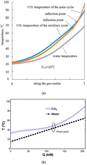
Figure 10.
(a) The temperature distribution of the combined gas cooler; (b) the pinch point location inside the gas cooler [35].
4.3. Predictive Correlation
Based on the simulation data presented above, a predictive correlation for the optimal intermediate temperature determination with ambient and water-feed temperature as the independent variables can be written as follows:
Moreover, 18 working conditions are selected, and corresponding prediction errors between the sought optimal intermediate temperatures and predictive values are indicated in Table 3 to reveal the prediction accuracy of the empirical correlation. The relative prediction errors are no more than 5%.
Table 3.
The prediction errors between the sought optimal intermediate temperatures and the predictive values.
4.4. Regulation of the Intermediate Temperature
In terms of adjustment methods of the intermediate temperature, the compressor speed ratio is manually adjusted to obtain a changeable compressor displacement ratio then changeable subcooling capacity in our previous works [33], by which the stepless regulation of the intermediate temperature can be achieved.
However, considering performance degradation under frequency conversion conditions and the cost of the frequency inverter, the regulation of the intermediate temperature will not be easy in practice. To the authors’ knowledge, two recommendations could be provided for adjusting the intermediate temperature: (i) using an additional water loop as the medium working fluid between the auxiliary cycle’s evaporator and main cycle’s subcooler, by which the direct heat transfer would be transferred in an indirect way as shown in the open literature [3]. The independently adjustable intermediate temperature could be achieved by regulating the mass flow rate of the water loop without any other changes. The variation of the water mass flow rate will bring about the different auxiliary cycle’s evaporator outlet water temperature, and thus the change of the main cycle’s gas-cooler inlet water temperature. It should be mentioned that the overall heat-transfer temperature difference will be a little higher and the heat-transfer efficiency will be a little lower when introducing the indirect way into systems; and (ii) employing two EEVs with a sandwiched vapor–liquid tank to replace the original EEV installed in the auxiliary cycle between the gas cooler and evaporator, as shown in the existing literature [36]. In this way, the control of the high-pressure side and the evaporating-pressure side could be decoupled, i.e., the first-stage EEV could be used to control the discharge pressure while the second-stage EEV could be used to control the evaporating pressure.
5. Conclusions
In this study, a dual transcritical CO2 system is discussed in a wide range of operating conditions. Based on the economic analyses in the literature [24,25], a conclusion is drawn that the dual system is advantageous in in an economic respect if it could be popularized, because higher heating performance and COP result in lower operating costs. Moreover, the optimal intermediate temperature of the dual system is studied based on theoretical simulation and corresponding results, and the main conclusions are as follows:
- (i)
- After comparison with the measurement data from our previous works, the veracity of the simulation models could be verified, which gives us the convenience to carry on the most discussion based on only the simulation results.
- (ii)
- The existence of optimal intermediate temperature is validated, while optimal values of the intermediate temperature increase with an increase in ambient temperature and water-feed temperature. Subsequently, the system COP also increases with an increase in ambient temperature, but decreases with the water-feed temperature.
- (iii)
- Due to the existence of the optimal intermediate temperature, the system performance rises first and then declines, while the auxiliary cycle’s performance rises gradually with the increase in intermediate temperature. As for the main cycle’s performance, no obvious rule could be observed.
- (iv)
- By using the dual gas cooler (the heat rejection of the auxiliary and main cycles is installed inside a same gas cooler), the negative effects of the pinch point on the heat transfer inside the heat exchanger could be greatly reduced.
- (v)
- A predictive correlation for the optimal intermediate temperature determination, with the ambient and water-feed temperature as the independent variables, is proposed, while the relative prediction errors are no more than 5% across 18 working conditions.
Author Contributions
Conceptualization, F.C. and Y.S.; Methodology, Y.S. and H.W.; Software, Y.S.; Validation, Y.S.; Formal Analysis, H.W.; Investigation, Y.S.; Resources, H.W.; Data Curation, H.W.; Writing-Original Draft Preparation, Y.S.; Writing-Review & Editing, H.W.; Visualization, Y.S.; Supervision, F.C. All authors have read and agreed to the published version of the manuscript.
Funding
The authors are grateful to the National Science and Technology Major Project (2017-III-0010-0036) for funding this research.
Conflicts of Interest
We declare that they have no known competing financial interests or personal relationships that could have appeared to influence the work reported in this paper.
Nomenclature
| A | Heat-transfer area (m2) |
| Specific heat capacity (kJ∙kg−1∙K−1) | |
| d | Diameter (m) |
| f | Friction factor |
| h | Enthalpy (kJ∙kg−1) |
| m | Mass flow rate (kg∙s−1) |
| p | Pressure (MPa) |
| Pr | Prandtl number |
| Q | Heat-transfer rate (kW) |
| R | Fouling resistance (K∙m2∙W−1) |
| Re | Reynolds number |
| T | Temperature (℃) |
| Power consumption (kW) | |
| Convective heat-transfer coefficient (W∙K-1∙m-2) | |
| Thickness of the fin (m) | |
| γ | heat leakage coefficient |
| Efficiency | |
| Conductivity (W∙K-1∙m-2) | |
| Density (kg∙m-3) | |
| Dehumidification coefficient | |
| Subscripts | |
| av | Average |
| air | air |
| comp | Compressor |
| eq | Equivalent |
| eva | Evaporator |
| f | feed |
| gc | Gas cooler |
| h | Heating |
| i | Inner |
| in | System inlet |
| is | Isentropic |
| out | System outlet |
| o | Outer |
| r | Refrigerant |
| single | Single phase |
| tube | tube |
| v | Volumetric |
| w | Water |
| wall | Tube wall |
References
- Lorentzen, G.; Pettersen, J. A new, efficient and ambientally benign system for car air conditioning. Int. J. Refrig. 1993, 16, 4–12. [Google Scholar] [CrossRef]
- Lorentzen, G. The use of natural refrigerant: A complete solution to the CFC/HCFC predicament. Int. J. Refrig. 1994, 18, 190–197. [Google Scholar] [CrossRef]
- Song, Y.; Cao, F. The evaluation of the optimal medium temperature in a space heating used transcritical air-source CO2 heat pump with an R134a subcooling device. Energy Convers. Manag. 2018, 166, 409–423. [Google Scholar] [CrossRef]
- Song, Y.; Ye, Z.; Wang, Y.; Cao, F. The experimental verification on the optimal discharge pressure in a subcooler-based transcritical CO2 system for space heating. Energy Build. 2018, 158, 1442–1449. [Google Scholar] [CrossRef]
- White, S.D.; Yarrall, M.G.; Cleland, D.J.; Hedley, R.A. Modeling the performance of a transcritical CO2 heat pump for high temperature heating. Int. J. Refrig. 2002, 25, 479–486. [Google Scholar] [CrossRef]
- Aprea, C.; Maiorino, A. An experimental evaluation of the transcritical CO2 refrigerator performances using an internal heat exchanger. Int. J. Refrig. 2008, 31, 1006–1011. [Google Scholar] [CrossRef]
- Zhang, F.; Jiang, P.; Lin, Y. Efficiencies of subcritical and transcritical CO2 inverse cycles with and without an internal heat exchanger. Appl. Therm. Eng. 2011, 31, 432–438. [Google Scholar] [CrossRef]
- Kim, S.G.; Kim, Y.J.; Lee, G.; Kim, M.S. The performance of a transcritical CO2 cycle with an internal heat exchanger for hot water heating. Int. J. Refrig. 2005, 28, 1064–1072. [Google Scholar] [CrossRef]
- Torrella, E.; Sanchez, D.; Llopis, R. Energetic evaluation of an internal heat exchanger in a CO2 transcritical refrigeration plant using experimental data. Int. J. Refrig. 2011, 34, 40–49. [Google Scholar] [CrossRef]
- Bertsch, S.S.; Groll, E.A. Two-stage air-source heat pump for residential heating and cooling applications in northern U.S. climates. Int. J. Refrig. 2008, 31, 1282–1292. [Google Scholar] [CrossRef]
- Xu, S.X.; Ma, G.Y. Experimental study on two-stage compression refrigeration/heat pump system with dual-cylinder rolling piston compressor. Appl. Therm. Eng. 2014, 62, 803–808. [Google Scholar]
- Redón, A.; Navarro-Peris, E.; Pitarch, M.; Gonzálvez-Macia, J.; Corberán, J.M. Analysis and optimization of subcritical two-stage vapor injection heat pump systems. Appl. Energy 2014, 124, 231–240. [Google Scholar] [CrossRef]
- Agrawal, N.; Souvik, B.; Sarkar, J. Optimization of two-stage transcritical carbon dioxide heat pump cycles. Int. J. Therm. Sci. 2007, 46, 180–187. [Google Scholar] [CrossRef]
- Baek, C.; Heo, J.; Jung, J. Effects of vapor injection techniques on the heating performance of a CO2 heat pump at low ambient temperatures. Int. J. Refrig. 2014, 43, 26–35. [Google Scholar] [CrossRef]
- Baek, C.; Heo, J.; Jung, J. Performance characteristics of a two-stage CO2 heat pump water heater adopting a sub-cooler vapor injection cycle at various operating conditions. Energy 2014, 77, 570–578. [Google Scholar] [CrossRef]
- Baek, C.; Heo, J.; Jung, J. Effects of the cylinder volume ratio of a twin rotary compressor on the heating performance of a vapor injection CO2 cycle. Appl. Therm. Eng. 2014, 67, 89–96. [Google Scholar] [CrossRef]
- Nakagawa, M.; Takeuchi, H. Performance of two-phase ejector in refrigeration cycle. In Proceedings of the Third International Conference on Multiphase Flow, Lyon, France, 8–12 June 1998; pp. 1–8. [Google Scholar]
- Elbel, S. Historical and present developments of ejector refrigeration systems with emphasis on transcritical carbon dioxide air-conditioning applications. Int. J. Refrig. 2011, 34, 1545–1561. [Google Scholar] [CrossRef]
- Zhu, Y.; Li, C.; Zhang, F.; Jiang, P. Comprehensive experimental study on a transcritical CO2 ejector-expansion refrigeration system. Energy Convers. Manag. 2017, 151, 98–106. [Google Scholar] [CrossRef]
- Boccardi, G.; Botticella, F.; Lillo, G. Experimental investigation on the performance of a transcritical CO2 heat pump with multi-ejector expansion system. Int. J. Refrig. 2017, 82, 389–400. [Google Scholar] [CrossRef]
- Sarkar, J. Performance optimization of transcritical CO2 refrigeration cycle with thermoelectric subcooler. Int. J. Energy Res. 2013, 37, 121–128. [Google Scholar] [CrossRef]
- Llopis, R.; Cabello, R.; Sanchez, D. Energy improvements of CO2 transcritical refrigeration cycles using dedicated mechanical subcooling. Int. J. Refrig. 2015, 55, 129–141. [Google Scholar] [CrossRef]
- Llopis, R.; Laura, A.; Cabello, R. Experimental evaluation of a CO2 transcritical refrigeration plant with dedicated mechanical subcooling. Int. J. Refrig. 2016, 69, 361–368. [Google Scholar] [CrossRef]
- Dai, B.; Liu, S.; Li, H. Energetic performance of transcritical CO2 refrigeration cycles with mechanical subcooling using zeotropic mixture as refrigerant. Energy 2018, 150, 205–221. [Google Scholar] [CrossRef]
- Dai, B.; Qi, H.; Liu, S. Evaluation of transcritical CO2 heat pump system integrated with mechanical subcooling by utilizing energy, exergy and economic methodologies for residential heating. Energy Convers. Manag. 2019, 192, 202–220. [Google Scholar] [CrossRef]
- Sarkar, J. Cycle parameter optimization of vortex tube expansion transcritical CO2 system. Int. J. Therm. Sci. 2009, 48, 1823–1828. [Google Scholar] [CrossRef]
- Song, Y.; Sun, Q.; Yang, S.; Xing, Q.; Cheng, L.; Cao, F. The theoretical and experimental research on the thermodynamic process in transcritical carbon dioxide piston compressor. IMech E Part E J. Process Mech. Eng. 2019, 233, 267–279. [Google Scholar] [CrossRef]
- Yang, D.; Song, Y.; Cao, F. Theoretical and experimental investigation of a combined R134a and transcritical CO2 heat pump for space heating. Int. J. Refrig. 2016, 72, 156–170. [Google Scholar] [CrossRef]
- Dang, C.; Eiji, H. In-tube cooling heat transfer of supercritical carbon dioxide, part 1. Experimental measurement. Int. J. Refrig. 2004, 27, 736–747. [Google Scholar] [CrossRef]
- Dang, C.; Eiji, H. In-tube cooling heat transfer of supercritical carbon dioxide, part 2. Comparison of numerical calculation with different turbulence models. Int. J. Refrig. 2004, 27, 748–760. [Google Scholar] [CrossRef]
- Cheng, L.; Ribatski, G.; Wojtan, L.; Thome, J.R. New flow boiling heat transfer model and flow pattern map for carbon dioxide evaporating inside horizontal tubes. Int. J. Heat Mass Transf. 2006, 49, 4082–4094. [Google Scholar] [CrossRef]
- Churchill, S.W.; Bernstein, M. A correlating equation for forced convection from gases and liquids to a circular cylinder in cross flow. ASME Transf. J. Heat Transf. 1977, 99, 300–306. [Google Scholar] [CrossRef]
- Cao, F.; Cui, C.; Wei, X. The experimental investigation on a novel transcritical CO2 heat pump combined system for space heating. Int. J. Refrig. 2019, 106, 539–548. [Google Scholar] [CrossRef]
- Sarkar, J.; Bhattacharyya, S.; Gopalm, M.R. Optimization of a transcritical CO2 heat pump cycle for simultaneous cooling and heating applications. Int. J. Refrig. 2004, 27, 830–838. [Google Scholar] [CrossRef]
- Chen, Y. Optimal heat rejection pressure of CO2 heat pump water heaters based on pinch point analysis. Int. J. Refrig. 2019, 106, 592–603. [Google Scholar] [CrossRef]
- Llopis, R.; Andres, L.; Sanchez, D. Subcooling methods for CO2 refrigeration cycles: A review. Int. J. Refrig. 2018, 93, 85–107. [Google Scholar] [CrossRef]


© 2020 by the authors. Licensee MDPI, Basel, Switzerland. This article is an open access article distributed under the terms and conditions of the Creative Commons Attribution (CC BY) license (http://creativecommons.org/licenses/by/4.0/).