Abstract
Solar thermochemical gasification is a promising solution for the clean production of low-emission synthetic fuels. It offers the possibility to upgrade various biomasses and waste feedstocks and further provides an efficient way to sustainably store solar energy into high-value and energy-intensive chemical fuels. In this work, a novel continuously-fed solar steam gasifier was studied using beechwood and solid recovered fuels (SRF) particles. Solar-only and hybrid solar/autothermal gasification experiments were performed at high temperatures to assess the performance of the reactor and its flexibility in converting various types of feedstocks. The hybrid operation was considered to increase the solar reactor temperature when the solar power input is not sufficient thanks to partial feedstock oxy-combustion. The hybrid solar process is thus a sustainable alternative option outperforming the conventional gasification processes for syngas production. Wood and waste particles solar conversion was successfully achieved, yielding high-quality syngas and suitable reactor performance, with Cold Gas Efficiencies (CGE) up to 1.04 and 1.13 respectively during the allothermal operation. The hybrid process allowed operating with a lower solar power input, but the H2 and CO yields noticeably declined. SRF gasification experiments suffered furthermore from ash melting/agglomeration issues and injection instabilities that undermined the continuity of the process. This study demonstrated the solar reactor flexibility in converting both biomass and waste feedstocks into syngas performed in continuous feeding operation. The experimental outcomes showed the feasibility of operating the reactor in both allothermal (solar-only) and hybrid allothermal/autothermal (combined solar and oxy-combustion heating) for continuous syngas production with high yields and energy conversion efficiencies.
1. Introduction
Gasification reactors have been available on the market for more than a century, with current applications in chemicals, liquid fuels, and power generation. These industrial reactors are based on the combustion of a part of the feedstock in order to provide the energy necessary to activate the strongly endothermic gasification reactions [1,2], which penalizes the material yield and the energy conversion efficiency. Various conventional gasifier technologies have been investigated so far at pilot/industrial scales. While Luleå University of Technology has mainly focused on black liquor gasification [3], Chalmer University of Technology [4] and Vienna University of Technology [5] operated dual fluidized bed reactors at temperatures below 950 °C for various carbonaceous loads and bed materials. Recent work has proposed an updated review about gasification in fluidized beds and compared solid recovered fuels and woody biomass gasification highlighting the gasification improvement with increasing temperature [6].
By combining concentrated solar energy and thermochemical gasification of carbonaceous materials, it is possible to take advantage of both resources. Indeed, since high-temperature solar heat can be used to provide the enthalpy of the reaction, all the feedstock (biomass, waste) can be converted into hydrogen and carbon monoxide (syngas).
The coupling of solar energy and thermochemical gasification can be achieved by either considering the two individual systems separately or jointly. The process with indirect coupling makes use of external solar receivers to harness the radiant energy and transmit it to a heat transfer fluid (HTF) such as steam [7], particulate materials [8], molten salt, or slag [9,10] flowing between the receiver and the chemical reactor. The process with direct coupling makes use of cavity-type solar reactors directly receiving the solar radiation at the reaction zone, in which the solar reactor is at the same time the solar receiver and the gasifier [11,12].
Experimental research at the laboratory scale has given preference to cavity-type solar reactors that ensure the highest temperatures, avoid the use of a HTF, and limit the heat losses caused by indirect heat transfer. Cavity-type solar gasifiers were extensively studied in many laboratories across the globe [13,14]. They can be directly [15,16,17,18,19] or indirectly [20,21,22,23] irradiated. Directly irradiated solar reactors expose the reactants directly to solar irradiation thanks to a transparent glass window. Indirectly irradiated gasifiers alternatively employ an opaque emissive plate that captures the concentrated sunlight and transfers it to the reaction zone mainly by radiative heat transfer.
Pioneering work on a directly irradiated packed bed steam gasifier was conducted by Gregg et al. in 1980 [24]. The developed reactor was used to convert different carbonaceous materials such as coke, coal, and activated carbon. It showed promising results with more than 20% of the incoming sunlight effectively stored as fuel calorific value in the product gas. Since then, other reactor designs, including packed beds [20,25], fluidized beds [18,26], spouted beds [15,27], vortex flow [21,28], drop tube [16,29], and molten salt [10,30] reactors were tested to convert a wide variety of feedstocks such as biomass, coal and different kinds of waste with either steam or CO2 as an oxidizing agent. Recent exploratory work on hybrid solar gasification makes use of O2 as a means to maintain the process temperature during sun-lacking periods thanks to combined solar heating and in-situ oxy-combustion [31,32,33,34]. Recently, the concept of coupling solar energy with thermochemical reactions to energetically upgrade biomass has been extended to hydrothermal processes [35,36].
At the CNRS-PROMES laboratory, a novel conical cavity-type solar reactor was built and experimentally tested under real concentrated solar-flux for beech wood biomass steam gasification at temperatures up to 1400 °C. The high-temperature operation avoids the tar formation generally observed in DFB gasifiers [37], while the concept can be operated without requiring bed materials, thus avoiding sintering and agglomeration issues [38,39]. Indeed, the operation temperature is much lower for DFB (700–900 °C vs. superior to 1200 °C for the solar spouted bed reactor). The behavior of ashes is totally different, given that they remain in solid state for DFB, while the melting temperature is reached in the spouted bed. Using this solar reactor concept, high conversion efficiencies were achieved with a carbon conversion rate of up to 94% and an upgrade of the feedstock calorific value by up to 1.21 [15]. However, questions persist about the ability of the reactor to treat more varied loads, such as wastes. Being essential for the scale-up as waste feedstocks offer an attractive way for improving the economic balance, the use of Municipal Solid Waste (MSW) and industrial waste (IW) as a primary feedstock has been barely discussed and investigated. Due to the complex nature of waste and its high content of ash, its efficient solar conversion in the reactor needs to be carefully examined. Often, the recovery of material and energy from MSW and IW is carried out through the production of refuse derived fuels (RDF) or solid recovered fuels (SRF). Prepared from plastic wastes, food packaging wastes including plastic, paper etc., SRF present several advantages over unprocessed wastes, since they are easier to handle with fairly constant physico-chemical properties and low chlorine content (generally below 1.5 wt.% [40]). Waste conversion is particularly attractive due to the possible economic benefit regarding the availability and often negative cost of the feedstock. However, due to the increased heterogeneity of waste compared to conventional biomass, the technical realization of such solar processes becomes more challenging regarding continuous feedstock injection and stable gas production throughput. Within this framework, gasification experiments were performed with beech wood particles and SRF in solar-only (steam gasification) and hybrid solar/autothermal (steam gasification with the addition of O2) heating conditions for the first time. The objective of this study was to demonstrate the feasibility of syngas production process from biomass and waste (solid recovered fuel) conversion in the prototype solar reactor. Results in terms of syngas yields, temperature profiles, gas flow rates and reactor performance metrics are analyzed. The goal was to assess the ability of the reactor to convert the wood and waste particles in allothermal and combined solar/autothermal operating modes, quantify the gas products for gas yields comparison, and identify the potential technical issues to be tackled for improving the reliability of the solar process.
2. Materials and Methods
The 60° angle conical reactor was positioned at the focus of a 2 m-parabolic solar furnace at CNRS-PROMES. The concentrated solar power entered the cavity through the aperture positioned at the focal point of the solar concentrator (Figure 1). The reactor was composed of an aperture (15 mm diameter) to let the concentrated solar radiation enter the reaction zone. During the experiments, a sun tracking heliostat was used to reflect the solar rays towards a parabolic mirror that, in turn, concentrated the radiation towards the reactor aperture. The feedstock was stored in a hopper (1.15 L capacity) and was continuously transported by a screw feeder driven by a motor. The particles fell into the directly irradiated cavity by gravity to react until complete conversion. An Ar flow (0.5 NL.min−1) was continuously injected in the hopper and then flowed via the screw path, so that the hot gas from the cavity could not interact with the feedstock. Moreover, a flow of Ar (2.0 NL.min−1) was also injected below the window to prevent the hot gas and the particles from entering the window area and soiling it. Oxidants (H2O and O2), mixed with 0.2 NL.min−1 of Ar were injected from a bottom central alumina tube at the cone base to get mixed with the injected reactive charge. The gas flows were supplied and controlled by mass flow controllers (MFC, Brooks Instruments model SLA5850S), while the liquid water flow was supplied by a mass flow controller (Horiba). A 1.5 cm layer of packed Al2O3 particles (3 mm diameter) was set at the cavity bottom above the gas injection tube to broaden the inlet gas jet over the entire conical cavity section and to protect the injection tube from the solid and liquid residues of pyrolysis and gasification [41].
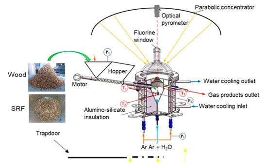
Figure 1.
Scheme of the solar reactor for biomass gasification.
The characteristics of the gasified SRF and wood particles with mm size are summarized in Table 1. Atomic composition (dry basis) was determined by CHNS elemental analysis (Elementar Vario EL Cube). Oxygen content was deduced by difference. The moisture content was measured by drying overnight a known amount of sample at 120 °C. The LHV (low heating value, dry basis) was measured with a PARR 6200 bomb calorimeter knowing humidity from NF EN14774 standard. The SRF sample, originally in the form of pellets, was crushed into particles with a diameter in the range 0–5 mm (Figure 2). The biggest particles were generally due to fragments of plastic, and the smallest particles had a foam-like texture. The wood particle size distribution was previously characterized by Camsizer XT (Retsch Company) by dynamic image analysis [42], and the mean particles’ diameter was 1 mm.

Table 1.
Feedstock characteristics (dry basis).
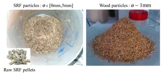
Figure 2.
SRF and wood samples preparation.
The volumetric screw feeder was calibrated at room temperature for the beechwood particles. Due to the heterogeneity of the SRF particles, a repeatable and precise calibration of the mass flow rate could not be achieved, and therefore, in the following, the actual SRF feeding rate was calculated by dividing the initial feedstock loaded mass over the injection duration.
The outlet gas flowed through a bubbler and micro-filters to remove excess steam and entrained char/soot particles from the produced syngas. To analyze the syngas composition, an online analyzer (GEIT 3100) measured continuously the main species contained in the outlet syngas (H2, CO, CO2, and CH4). Then, a gas chromatograph equipped with two columns using Ar as carrier gas (micro GC, Varian CP4900) was used to check and confirm the online analysis measurements. The reactor temperature was measured by B-type thermocouples inserted inside the conical part of the cavity (T1 at the cavity center and T3 near the bottom of the cavity in the conical region) and at the external cavity surface (T2). Their tips were protected from the reacting gases with an alumina shielding tube. To confirm the thermocouple measurements, a “solar-blind” optical pyrometer (Impac, operating at 4.8–5.2 μm in a H2O absorption band) placed at the center of the parabolic mirror was utilized to directly measure the temperature inside the cavity through a calcium fluoride window (installed at the top of the transparent window). Three pressure measurements were set in the window area (P1), in the cavity (P2), and in the hopper (P3). A Venturi vacuum pump placed at the end of the outlet tube was used to control and maintain the reactor pressure below 1 bar corresponding to atmospheric pressure (atmospheric pressure at experimental site elevation (altitude of 1600 m) was ~ 0.85–0.90 bar) throughout the experiments and to facilitate gas evacuation. All the obtained data were controlled and collected by an automated data acquisition system (BECKHOFF). After the solar experiments, the mass balance was checked by comparing the mass of fed reactants (biomass and water) and the mass of products outputs, including syngas components, excess water (condensed in the outlet components), and entrained char/soot/tar trapped in bubbler and filters.
3. Results and Discussion
Experiments were performed in allothermal and hybrid solar-autothermal heating conditions with beechwood and SRF under very stable solar DNI (direct normal irradiation) conditions (maximum DNI variation lower than 3%). Table 2 recaps the operating conditions and the calculated (S/B)/(S/B)st steam to biomass mass ratio (st in subscript means stoichiometric) based on Equations (1) and (2).
Table 2.
Operating conditions.
Wood steam gasification:
C6.0H10.0O4.1+1.9H2O(v)→6.0CO+6.9H2 ∆H°g,1 = 0.86 MJ∙mol−1
SRF steam gasification:
C6H8.4O2.4+3.6H2O(v)→6.0CO+7.8H2 ∆H°g,2 = 1.14 MJ∙mol−1
Runs#1,3 were performed under allothermal conditions (solar-only heating), Run#2 was similar to Run#1 but with oxygen injection for partial oxy-combustion (hybrid operation), whereas Run#4 was first carried out in allothermal followed by hybrid operation mode (with the injection of 0.20 NL/min of O2). For the hybrid solar/autothermal experiments (Runs#2,4), the particles were partially burnt under oxygen lean conditions. The Equivalence Ratio ER = (B/O)/(B/O)st Biomass to Oxygen mass ratio (equivalent to the fuel to oxidizer ratio [43]) was 4.95 in Run#2 and 2.74 in Run#4 based on Equations (3) and (4).
Wood oxy-combustion:
C6.0H10.0O4.1+6.4O2→6.0CO2+5.0H2O ∆H°c,3 = −2.49 MJ∙mol−1
SRF oxy-combustion:
C6H8.4O2.4+6.9O2→6.0CO2+4.2H2O ∆H°c,4 = −2.45 MJ∙mol−1
The duration of gasification experiments corresponds to the time required to inject the whole amount of feedstock loaded in the feeding system. This duration could be increased by decreasing the feeding rate or by increasing the amount of feedstock. The experimental duration is not the main parameter influencing the gasification performance, given that the injection is continuous. The total experimental duration also includes the heating and stabilization periods as well as transition periods (feedstock injection stopped) when switching from allothermal to hybrid operation. The feeding rate is actually the key parameter affecting the process, as previously evidenced in the case of wood biomass gasification [44]. In this study, it was chosen so as to offer stable gasification performance at the reactor operating conditions. Indeed, a low feeding rate means the reactor is not used at its nominal capacity, whereas a too high feeding rate results in continuous operation failure because the input energy is not high enough to gasify the fed particles. Thus, the optimal feeding rate existing for given operating conditions (reactor temperature and solar energy input) was selected.
The time-dependent species production rate (Fi) was calculated from the known inlet flow rate of inert gas (FAr) and the measured species outlet mole fractions (xi) following Equation (5).
The average syngas composition and gas yields (in mmol/gdry,feedstock) were thereafter evaluated thanks to the time integration of the gas production rates. The performance of the reactor was evaluated using three relevant performance metrics: the carbon conversion efficiency (CCE), Equation (6); the cold gas efficiency (CGE), Equation (7); and the solar-to-fuel efficiency (SFE). Equation (8). The CCE quantifies the extent of feedstock conversion inside the reactor (ratio of carbon contained in the syngas to carbon in the initial feedstock). The CGE (also called energy upgrade factor) is the ratio of the calorific value of produced syngas to that of the initial feedstock, each multiplied by its mass (where LHV is the low heating value (J/kg) and msyngas, mfeedstock are the mass of produced syngas and initial feedstock (kg)). The SFE represents the ratio between the calorific value of produced syngas over the total thermal energy that enters the reactor, including both solar and injected feedstock energy.
3.1. Beechwood Gasification
The measurements of outlet gas production rates by online syngas analysis (continuous lines) and GC analysis (dots) are shown in Figure 3. Syngas flow rate evolutions fluctuate around a mean value throughout the experiment. These fluctuations were due to the screw feeder outlet that could not be inserted in the reaction zone due to high temperatures, hence, the woody particles in the injection tube were pushed by preceding ones and fell by gravity into the cavity in the form of small parcels. In Run#1, 1.2 g.min−1 of biomass was gasified by 0.2 g.min−1 of steam (Figure 3a). In Run#2, 0.25 NL.min−1 of O2 was added to the system with 0.2 g.min−1 of extra-wood injection (Figure 3b); the oxygen flow corresponds to the quantity required to completely burn the extra-wood injection.
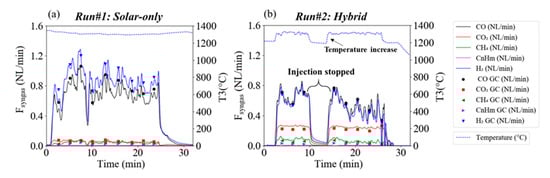
Figure 3.
Syngas flow rates in (a) Run#1 (solar-only) and (b) Run#2 (hybrid) and T3 temperature evolution (in °C).
The solar power in Run#1 was about 1.2 kWth, it decreased significantly in Run#2 to 0.8 kWth (Figure 4a) as part of the energy was provided by internal exothermic gas/solid oxy-combustion reactions. The experiments were performed at 1300 °C and above (according to T3 inserted inside the cavity; Figure 4b). Thanks to the achieved high temperatures, the gas in Run#1 (Figure 3a) was predominantly composed of H2 and CO. CO2 and light hydrocarbons (CH4 and CnHm, mainly C2H2 and to a lesser extent C2H4) were produced in lesser amount in accordance with previously reported works [45,46]. Although the biomass feeding rate was increased in Run#2 from 1.2 g.min−1 to 1.4 g.min−1, H2 and CO flow rates declined consistently (oxidation of these gases by the added O2 thus likely occurred), and CO2 sharply increased (H2O should also be produced from H2 oxidation, but it was not quantified because it was trapped in the outlet bubbler). Accordingly, the syngas composition was substantially affected by the presence of O2, as expected. The time-averaged volume fractions for Runs#1,2 were respectively: H2 (52.2%, 37.1%), CO (41.6%, 39.4%), CO2 (3.4%, 16.8%), CH4 (2.5%, 4.7%), and CnHm (1.3%, 2.0%).
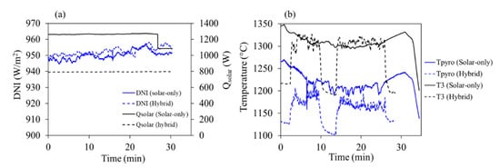
Figure 4.
(a) Solar power input and DNI; (b) reactor temperatures for the two heating modes.
The CnHm molar composition was very similar in the two runs: C2H2 (87.0–85.9%), C2H4 (13.0–14.0%) and C2H6 (<0.1%). Their time-dependent production rates, measured by the GC, are plotted in Figure 5.
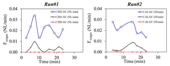
Figure 5.
GC analysis of CnHm during Runs#1,2.
Mass balance, syngas yields, and reactor performance indicators are shown in Table 3 and Table 4. The results reveal that H2 and CO yields both declined respectively by 43% and 26% while CH4 and CnHm increased by 48% and 21%, probably due to lower gas residence time (0.51 s in Run#1 against 0.48 s in Run#2). CO2 yield was highly impacted and increased by almost 3 times due to oxy-combustion reactions. The greater decrease in hydrogen would be related to its higher concentration in the cavity [42] and its greater reactivity with oxygen [47]. This suggests that the gaseous products from gasification are oxidized/combusted by oxygen rather than the raw biomass. CO also decreased but, to a lesser extent, probably because it is also produced by partial oxidation of gases (methane, light hydrocarbons and tars) and char.
Table 3.
Gas yield and mass balance closure for beechwood gasification.
Table 4.
Performance metrics for beechwood gasification.
Although gas residence time decreased in Run#2, oxygen injection globally favored biomass conversion. In fact, the CCE was slightly improved from 83.3% in Run#1 to 84.6% in Run#2 due to the very fast O2-char reaction kinetics. Moreover, given the decrease in H2 and CO yields, the CGE declined strongly from 112.9% in Run#1 to 84.7% in Run#2. In return, the SFE was almost the same at around 17.6% in both heating configurations given that the total solar energy consumed in Run#2 was significantly lower by about 41% than in Run#1.
Globally, beechwood particles were successfully converted in both solar-only and hybrid solar/autothermal operating modes. The hybrid process provided additional combustion heat to the reactor and reduced the solar energy consumption at the expense of lower H2 and CO yields.
In the following, the ability of the reactor to operate with SRF particles in both solar-only (allothermal) and hybrid solar/autothermal heating modes is investigated.
3.2. Solid Recovered Fuels Gasification
Figure 6 shows the measurements of the syngas flow rates with the SRF particles (Runs#3,4). Noticeable fluctuations in the gas flow rates reflected by variable peaks and valleys all along the experiments were observed. They were due to the unstable injection of the particles caused by the heterogeneity of the sample and the possible melting of plastics and inorganics at the screw feeder tip and at the injection tube that affect the particles’ flowability. In spite of this issue, complete feedstock load injection was achieved. Run#3 was performed at 1300 °C under solar-only heating conditions while Run#4 was also partly operated in solar hybrid mode.
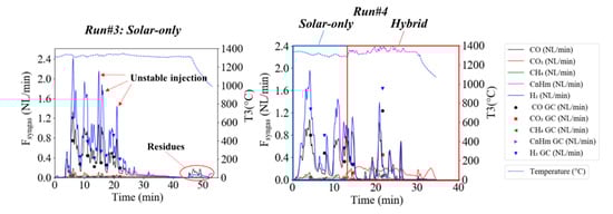
Figure 6.
Syngas flow rates in Run#3 (solar-only) and Run#4 (hybrid) and T3 temperature in °C.
Just as in Run#1 (using beech wood particles), H2 and CO flow rates were the highest, followed by CO2, CH4, and CnHm. GC measurements of the CnHm are shown in Figure 7. They were primarily composed of C2H2, whereas C2H4 and C2H6 were found in negligible amounts.
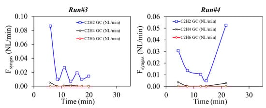
Figure 7.
GC analysis of CnHm during Runs#3,4.
Thermodynamic equilibrium calculations (Figure 8) have been performed thanks to the open source software CANTERA [48] to compare with the experimental data (the initial system compositions used in thermodynamic calculations take into account the feedstock composition and the inlet gas atmosphere for Run#3 and #4). The reaction equilibrium thermodynamics agree with the experimental values observed in terms of trends of the syngas species (especially H2 and CO predicted at temperatures above ~900–1000 °C). More specifically, the results evidence the increasing amount of CO2 and H2O, and the decreasing amount of H2 and to a lesser extent of CO when O2 is introduced at high temperatures (above 800 °C). However, kinetic limitations explain the presence of additional compounds such CH4 or C2 light hydrocarbons in the experiments. The main reactions are pyrolysis followed by steam gasification of carbon (char) that yields H2 and CO. The additional steam reforming and water gas shift reactions proceed in the gaseous phase and are thus influenced by the gas residence time. Thermodynamics consider that gas residence times are sufficiently long to reach reaction equilibrium conditions, which is not the case experimentally.
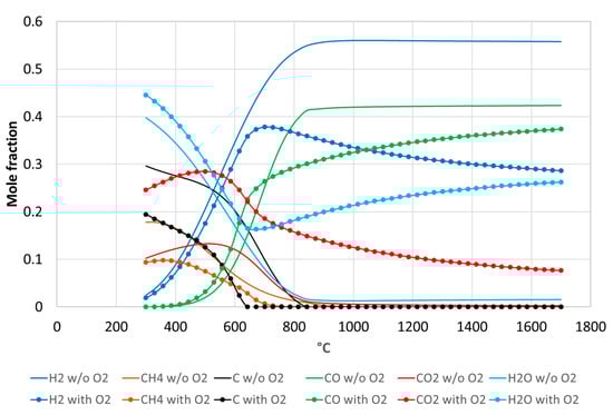
Figure 8.
Thermodynamic equilibrium calculation for the chemical system compositions corresponding to Run#3 (without O2, initial composition for calculation: C = 0.026 mol, H2 = 0.035 mol, O2 = 0.014 mol) and Run#4 (with O2, initial composition for calculation: C = 0.027 mol, H2 = 0.033 mol, O2 = 0.023 mol) at 1 bar.
The chemical composition of the syngas during this Run#3 was thus: H2 (56.8%), CO (32.1%), CO2 (7.3%), CH4 (2.3%), CnHm (1.5%). To study the flexibility of the solar process and its ability to deal with solar energy variations, a small amount of O2 (0.25 NL/min), calculated assuming the complete combustion of about 33% of the feedstock, was added to the system in Run#4 at time = 13 min. According to the previous results of Run#2, O2 injection is expected to elevate and stabilize the reactor temperature at a higher setpoint value.
The reactor temperature measurements during Runs#3,4 are plotted in Figure 9. While the temperature was quite stable in Run#3, the hybrid operation (Run#4) showed a fluctuating temperature pattern. The fluctuations were increased significantly during the hybrid phase at around 1350 °C and were due to the rapid oxy-combustion of the particles. In fact, the consumption of the particles was faster than the injection process leading to sharp temperature variations by about 80 °C. During the hybrid phase of Run#4, T3 temperature increased unsteadily. As a consequence, the desired effect of increasing and stabilizing the reactor temperature at a higher setpoint value through partial feedstock oxy-combustion was not totally effective due to the injection issues. Therefore, the impact on the gas composition was considerable and affected essentially the H2 and CO2 content.
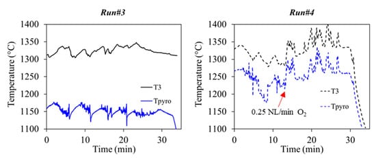
Figure 9.
Reactor temperatures in Run#3 (solar-only) and Run#4 (both solar and solar-hybrid).
Figure 10a shows the gas volume fractions before and after hybridization (Run#4). The H2 volume fraction decreased by 24% (58.9–40.0%), and CO2 increased by more than 5 times (3.5–24.0%), while CO concentration was only slightly affected with a decrease of 6% (33.8–31.8%).
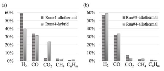
Figure 10.
(a) Syngas composition during Run#4 (allothermal vs. hybrid phase; (b) Syngas composition (Run#3 vs. allothermal part of Run#4).
To assess the consistency and repeatability of the measurements, the syngas compositions of the Run#3 and Run#4-allothermal were compared in Figure 10b (even if the water flow-rate varied slightly between the two runs). It can be observed that globally the composition was not significantly modified, except for the CO2 that was somewhat higher and CH4 that was slightly lower during Run#3 (CO2, 7–4%; CH4, 2–3%). This confirms that syngas composition outputs are similar for comparable operating conditions, which demonstrates results repeatability. Indeed, in spite of the experimental instabilities linked to the SRF injection, a good agreement was achieved.
The mass balance, syngas yields (integrated over the total experiment), and reactor performance metrics are shown in Table 5 and Table 6. The injection of oxygen significantly affected the gas yields. Although the first part of the hybrid run (Run#4) was carried out in allothermal mode, the drop in the H2 and CO yields, calculated over the whole run#4, was noticeable (by respectively 31% and 20%). Light hydrocarbons slightly decreased and the CO2 yield in the hybrid run increased by about 37%.
Table 5.
Gas yield and mass balance closure for SRF gasification.
Table 6.
Performance metrics for SRF gasification.
The achieved CCE in Run#3 was 88.1%, which is in the range of the reported CCE values (generally between 80–92%) for waste gasification in autothermal fluidized beds operating up to 800 °C [49]. The CGE was 104.5%, which was much greater than the reported CGE values for SRF gasification in autothermal fluidized bed gasifiers that vary between 70% and 85% at best [6,50,51]. The CGE higher than 1 confirms that solar energy was effectively stored in the gas products, and this demonstrates the interest and benefits of solar heating for gasification when compared with autothermal operation (involving partial feedstock combustion). The SFE was 15.8%. In Run#4-hybrid phase, the O2 injection impaired to a certain extent the production of H2 and CO in comparison with Run#3. It also affected SRF conversion and led to a relative CCE drop by 11%. Likewise, the CGE and the SFE were also decreased to reach barely 78.0% and 11.9%.
These experiments further allowed identifying technical issues to be addressed regarding SRF solar gasification. In addition to the difficulties encountered for the transport during the injection of the SRF particles, the process suffered from ash melting and agglomeration issues. Figure 11 depicts the cavity and ash deposition at the bottom at the end of Run#4. A thick block of solidified ash stuck to the cavity wall. It surrounded the fixed Al2O3 particles bottom layer that was used to protect the oxidant injection tube. Future work should be dedicated to manage ash accumulation in the reactor.
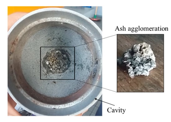
Figure 11.
Ash agglomeration at the bottom of the conical cavity.
4. Conclusions
Solar-only and solar-hybrid gasification experiments with beech wood and SRF particles as biomass and waste feedstocks were performed. This study demonstrated the feasibility of syngas production from the thermochemical conversion of biomass and waste (solid recovered fuel) feedstocks in the prototype solar reactor. The particles’ conversion during allothermal operation showed high gasification performance with an upgrade of the calorific value of the feedstocks by respectively 1.13 and 1.04. Hybrid solar/autothermal conversion of beechwood particles chiefly increased the reactor temperature and reduced solar energy consumption. SRF particles conversion suffered from feedstock injection instabilities, which affected the temperature increase in the hybrid operation. In both configurations (biomass and waste gasification), a noticeable decrease in the H2 and CO yields was observed, while CO2 greatly increased. This impaired the syngas quality and heating value. The experimentally observed trends were consistent with the thermodynamic equilibrium predictions for the main gases at high temperatures (above 800 °C). More specifically, the equilibrium results clearly evidenced that O2 introduction increased the amount of CO2 and H2O, while the amounts of H2 and to a lesser extent of CO were decreased. Another issue encountered with the SRF particles concerned the melting/agglomeration of ash at the bottom of the conical reactor. This issue needs to be correctly managed for reliable operation. This study demonstrated the solar reactor flexibility in converting both biomass and waste feedstocks into syngas performed in continuous operation. The experimental results showed the feasibility of operating the reactor in both allothermal (solar-only) and hybrid allothermal/autothermal (combined solar and oxy-combustion heating) for continuous syngas production with high yields and energy conversion efficiencies. This study thus demonstrated the suitability of the technology concept coupling solar energy to sustain gasification, the reliability of the prototype solar reactor for both biomass and waste gasification, and the capability for continuous process operation under intermittent or fluctuating solar irradiation conditions by combining both allothermal and hybrid operation. Future work will focus on the improvement of the reactor design thanks to numerical simulation and high-temperature experimentation. Also, a sensitivity study based on thermodynamic equilibrium or on more complex kinetic modeling is required to find optimal biomass/water/oxygen flow-rates. The co-gasification of wood biomass and SRF will also be studied as an efficient strategy to limit the formation of ash while providing potential synergistic benefits for enhancing gasification performance.
Author Contributions
Conceptualization, H.B., S.R., and S.A.; methodology, H.B., S.R., and S.A.; validation, H.B., S.R., and S.A.; formal analysis, H.B., S.R., and S.A.; investigation, H.B., S.R., and S.A.; data curation, H.B., S.R. and S.A.; writing—original draft preparation, H.B.; writing—review and editing, S.R. and S.A.; visualization, H.B.; supervision, S.R. and S.A.; project administration, S.R. and S.A.; funding acquisition, S.R. and S.A. All authors have read and agreed to the published version of the manuscript.
Funding
This research received no external funding.
Acknowledgments
This study was supported by ADEME (French Environment and Energy Management Agency). We thank SIBUET Company for providing SRF raw samples and Serge Ravel for the feedstock analysis.
Conflicts of Interest
The authors declare no conflict of interest.
References
- Probstein, R.F.; Hicks, E.H. Synthetic Fuels; Dover Publications Inc.: Mineola, NY, USA, 2006; p. 11501. [Google Scholar]
- Breault, R.W. Gasification processes old and new: A basic review of the major technologies. Energies 2010, 3, 216–240. [Google Scholar] [CrossRef]
- Jafri, Y.; Furusjö, E.; Kirtania, K.; Gebart, B.R. Performance of a pilot-scale entrained-flow black liquor gasifier. Energy Fuels 2016, 30, 3175–3185. [Google Scholar] [CrossRef]
- Larsson, A.; Seemann, M.; Neves, D.; Thunman, H. Evaluation of performance of industrial-scale dual fluidized bed gasifiers using the chalmers 2–4-MWth gasifier. Energy Fuels 2013, 27, 6665–6680. [Google Scholar] [CrossRef]
- Pfeifer, C.; Koppatz, S.; Hofbauer, H. Steam gasification of various feedstocks at a dual fluidised bed gasifier: Impacts of operation conditions and bed materials. Biomass Convers. Biorefinery 2011, 1, 39–53. [Google Scholar] [CrossRef]
- Valin, S.; Ravel, S.; De Vincent, P.P.; Thiery, S.; Miller, H. Fluidized bed air gasification of solid recovered fuel and woody biomass: Influence of experimental conditions on product gas and pollutant release. Fuel 2019, 242, 664–672. [Google Scholar] [CrossRef]
- Wu, H.; Liu, Q.; Bai, Z.; Xie, G.; Zheng, J.; Su, B. Thermodynamics analysis of a novel steam/air biomass gasification combined cooling, heating and power system with solar energy. Appl. Therm. Eng. 2020, 164, 114494. [Google Scholar] [CrossRef]
- Guo, P.; Saw, W.L.; Van Eyk, P.; Ashman, P.; Nathan, G.; Stechel, E. Fischer-tropschliquid fuel production by co-gasification of coal and biomass in a solar hybrid dual fluidized bed gasifier. Energy Procedia 2015, 69, 1770–1779. [Google Scholar] [CrossRef]
- Bruckner, A.P. Continuous duty solar coal gasification system using molten slag and direct-contact heat exchange. Sol. Energy 1985, 34, 239–247. [Google Scholar] [CrossRef]
- Hathaway, B.J.; Davidson, J.H. Demonstration of a prototype molten salt solar gasification reactor. Sol. Energy 2017, 142, 224–230. [Google Scholar] [CrossRef]
- Loutzenhiser, P.G.; Muroyama, A.P. A review of the state-of-the-art in solar-driven gasification processes with carbonaceous materials. Sol. Energy 2017, 156, 93–100. [Google Scholar] [CrossRef]
- Arnavat, M.P.; Tora, E.; Bruno, J.C.; Coronas, A. State of the art on reactor designs for solar gasification of carbonaceous feedstock. Sol. Energy 2013, 97, 67–84. [Google Scholar] [CrossRef]
- Yadav, D.; Banerjee, R. A review of solar thermochemical processes. Renew. Sustain. Energy Rev. 2016, 54, 497–532. [Google Scholar] [CrossRef]
- Chuayboon, S.; Abanades, S. An overview of solar decarbonization processes, reacting oxide materials, and thermochemical reactors for hydrogen and syngas production. Int. J. Hydrog. Energy 2020, 45, 25783–25810. [Google Scholar] [CrossRef]
- Bellouard, Q.; Rodat, S.; Abanades, S.; Ravel, S.; Frayssines, P.-É. Design, simulation and experimental study of a directly-irradiated solar chemical reactor for hydrogen and syngas production from continuous solar-driven wood biomass gasification. Int. J. Hydrog. Energy 2019, 44, 19193–19205. [Google Scholar] [CrossRef]
- Bellouard, Q.; Rodat, S.; Dupassieux, N.; Abanades, S. A high temperature drop-tube and packed-bed solar reactor for continuous biomass gasification. AIP Conf. Proc. 2017, 1850, 100001. [Google Scholar] [CrossRef]
- Kodama, T.; Kondoh, Y.; Tamagawa, T.; Funatoh, A.; Shimizu, K.-I.; Kitayama, Y. Fluidized bed coal gasification with CO2 under direct irradiation with concentrated visible light. Energy Fuels 2002, 16, 1264–1270. [Google Scholar] [CrossRef]
- Gokon, N.; Ono, R.; Hatamachi, T.; Liuyun, L.; Kim, H.-J.; Kodama, T. CO2 gasification of coal cokes using internally circulating fluidized bed reactor by concentrated Xe-light irradiation for solar gasification. Int. J. Hydrog. Energy 2012, 37, 12128–12137. [Google Scholar] [CrossRef]
- Zgraggen, A.; Haueter, P.; Trommer, D.; Romero, M.; DeJesus, J.; Steinfeld, A. Hydrogen production by steam-gasification of petroleum coke using concentrated solar power—II Reactor design, testing, and modeling. Int. J. Hydrog. Energy 2006, 31, 797–811. [Google Scholar] [CrossRef]
- Piatkowski, N.; Wieckert, C.; Steinfeld, A. Experimental investigation of a packed-bed solar reactor for the steam-gasification of carbonaceous feedstocks. Fuel Process. Technol. 2009, 90, 360–366. [Google Scholar] [CrossRef]
- Müller, F.; Poživil, P.; Van Eyk, P.; Villarrazo, A.; Haueter, P.; Wieckert, C.; Nathan, G.; Steinfeld, A. A pressurized high-flux solar reactor for the efficient thermochemical gasification of carbonaceous feedstock. Fuel 2017, 193, 432–443. [Google Scholar] [CrossRef]
- Lichty, P.; Perkins, C.; Woodruff, B.; Bingham, C.; Weimer, A. Rapid high temperature solar thermal biomass gasification in a prototype cavity reactor. J. Sol. Energy Eng. 2010, 132, 011012. [Google Scholar] [CrossRef]
- Kruesi, M.; Jovanovic, Z.R.; Santos, E.C.D.; Yoon, H.C.; Steinfeld, A. Solar-driven steam-based gasification of sugarcane bagasse in a combined drop-tube and fixed-bed reactor—Thermodynamic, kinetic, and experimental analyses. Biomass Bioenergy 2013, 52, 173–183. [Google Scholar] [CrossRef]
- Gregg, D.; Taylor, R.; Campbell, J.; Taylor, J.; Cotton, A. Solar gasification of coal, activated carbon, coke and coal and biomass mixtures. Sol. Energy 1980, 25, 353–364. [Google Scholar] [CrossRef]
- Piatkowski, N.; Steinfeld, A. Solar-driven coal gasification in a thermally irradiated packed-bed reactor. Energy Fuels 2008, 22, 2043–2052. [Google Scholar] [CrossRef]
- Abe, T.; Gokon, N.; Izawa, T.; Kodama, T. Internally-circulating fluidized bed reactor using thermal storage material for solar coal coke gasification. Energy Procedia 2015, 69, 1722–1730. [Google Scholar] [CrossRef][Green Version]
- Boujjat, H.; Rodat, S.; Chuayboon, S.; Abanades, S. Experimental and CFD investigation of inert bed materials effects in a high-temperature conical cavity-type reactor for continuous solar-driven steam gasification of biomass. Chem. Eng. Sci. 2020, 228, 115970. [Google Scholar] [CrossRef]
- Z’Graggen, A.; Steinfeld, A. A two-phase reactor model for the steam-gasification of carbonaceous materials under concentrated thermal radiation. Chem. Eng. Process. Process. Intensif. 2008, 47, 655–662. [Google Scholar] [CrossRef]
- Bellouard, Q.; Abanades, S.; Rodat, S.; Dupassieux, N. Solar thermochemical gasification of wood biomass for syngas production in a high-temperature continuously-fed tubular reactor. Int. J. Hydrog. Energy 2017, 42, 13486–13497. [Google Scholar] [CrossRef]
- Hathaway, B.J.; Kittelson, D.; Davidson, J.H. Development of a molten salt reactor for solar gasification of biomass. Energy Procedia 2014, 49, 1950–1959. [Google Scholar] [CrossRef]
- Muroyama, A.P.; Guscetti, I.; Schieber, G.L.; Haussener, S.; Loutzenhiser, P.G. Design and demonstration of a prototype 1.5 kWth hybrid solar/autothermal steam gasifier. Fuel 2018, 211, 331–340. [Google Scholar] [CrossRef]
- Boujjat, H.; Rodat, S.; Chuayboon, S.; Abanades, S. Experimental and numerical study of a directly irradiated hybrid solar/combustion spouted bed reactor for continuous steam gasification of biomass. Energy 2019, 189, 116118. [Google Scholar] [CrossRef]
- Boujjat, H.; Junior, G.M.Y.; Rodat, S.; Abanades, S. Dynamic simulation and control of solar biomass gasification for hydrogen-rich syngas production during allothermal and hybrid solar/autothermal operation. Int. J. Hydrog. Energy 2020, 45, 25827–25837. [Google Scholar] [CrossRef]
- Rodat, S.; Abanades, S.; Boujjat, H.; Chuayboon, S. On the path toward day and night continuous solar high temperature thermochemical processes: A review. Renew. Sustain. Energy Rev. 2020, 132, 110061. [Google Scholar] [CrossRef]
- Ischia, G.; Castello, D.; Orlandi, M.; Miotello, A.; Rosendahl, L.A.; Fiori, L. Waste to biofuels through zero-energy hydrothermal solar plants: Process design. Chem. Eng. Trans. 2020, 80, 7–12. [Google Scholar]
- Ischia, G.; Orlandi, M.; Fendrich, M.; Bettonte, M.; Merzari, F.; Miotello, A.; Fiori, L. Realization of a solar hydrothermal carbonization reactor: A zero-energy technology for waste biomass valorization. J. Environ. Manag. 2020, 259, 110067. [Google Scholar] [CrossRef]
- Arena, U.; Di Gregorio, F. Gasification of a solid recovered fuel in a pilot scale fluidized bed reactor. Fuel 2014, 117, 528–536. [Google Scholar] [CrossRef]
- Fryda, L.; Panopoulos, K.; Kakaras, E. Agglomeration in fluidised bed gasification of biomass. Powder Technol. 2008, 181, 307–320. [Google Scholar] [CrossRef]
- Kirnbauer, F.; Hofbauer, H. Investigations on bed material changes in a dual fluidized bed steam gasification plant in Gussing, Austria. Energy Fuels 2011, 25, 3793–3798. [Google Scholar] [CrossRef]
- ADEME. État de l’art de la Production et de l’utilisation de Combustibles Solides de. 2012. Available online: https://www.ademe.fr/etat-lart-production-lutilisation-combustibles-solides-recuperation (accessed on 20 September 2020).
- Bellouard, Q.; Abanades, S.; Rodat, S. Biomass gasification in an innovative spouted-bed solar reactor: Experimental proof of concept and parametric study. Energy Fuels 2017, 31, 10933–10945. [Google Scholar] [CrossRef]
- Boujjat, H.; Rodat, S.; Chuayboon, S.; Abanades, S. Numerical simulation of reactive gas-particle flow in a solar jet spouted bed reactor for continuous biomass gasification. Int. J. Heat Mass Transf. 2019, 144, 118572. [Google Scholar] [CrossRef]
- Speight, J.G. Combustion of Hydrocarbons, in Handbook of Industrial Hydrocarbon Processes; Elsevier: Amsterdam, The Nederland, 2011. [Google Scholar]
- Chuayboon, S.; Abanades, S.; Rodat, S. Insights into the influence of biomass feedstock type, particle size and feeding rate on thermochemical performances of a continuous solar gasification reactor. Renew. Energy 2019, 130, 360–370. [Google Scholar] [CrossRef]
- Chuayboon, S.; Abanades, S.; Rodat, S. Experimental analysis of continuous steam gasification of wood biomass for syngas production in a high-temperature particle-fed solar reactor. Chem. Eng. Process. Process. Intensif. 2018, 125, 253–265. [Google Scholar] [CrossRef]
- Chuayboon, S.; Abanades, S.; Rodat, S. Comprehensive performance assessment of a continuous solar-driven biomass gasifier. Fuel Process. Technol. 2018, 182, 1–14. [Google Scholar] [CrossRef]
- Glassman, I. Combustion, 3rd ed.; Academic Press: New York, NY, USA, 1996; p. 631. [Google Scholar]
- Goodwin, D.G.; Speth, R.L.; Moffat, H.K.; Weber, B.W. Cantera: An Object-Oriented Software Toolkit for Chemical Kinetics, Thermodynamics, and Transport Processes. 2017. Available online: https://zenodo.org/record/1174508#.X3KE1-0RVEY (accessed on 24 August 2018).
- Kwon, E.; Westby, K.J.; Castaldi, M.J. Transforming Municipal Solid Waste (MSW) into fuel via the gasification/pyrolysis process. In North American Waste-to-Energy Conference, Proceedings of the 18th Annual North American Waste-to-Energy Conference, Orlando, FL, USA, 11–13 May 2010; ASME International: New York, NY, USA, 2010; pp. 53–60. [Google Scholar]
- Khosasaeng, T.; Suntivarakorn, R. Effect of equivalence ratio on an efficiency of single throat downdraft gasifier using RDF from municipal solid waste. Energy Procedia 2017, 138, 784–788. [Google Scholar] [CrossRef]
- Materazzi, M.; Lettieri, P.; Taylor, R.; Chapman, C. Performance analysis of RDF gasification in a two stage fluidized bed–plasma process. Waste Manag. 2016, 47, 256–266. [Google Scholar] [CrossRef]


© 2020 by the authors. Licensee MDPI, Basel, Switzerland. This article is an open access article distributed under the terms and conditions of the Creative Commons Attribution (CC BY) license (http://creativecommons.org/licenses/by/4.0/).