Article

A Novel Single-Wire Power Transfer Method for Wireless Sensor Networks

Tianjin Key Laboratory of Advanced Electrical Engineering and Energy Technology, Tiangong University, Tianjin 300387, China
*
Author to whom correspondence should be addressed.
Energies 2020, 13(19), 5182; https://doi.org/10.3390/en13195182
Submission received: 8 September 2020 / Revised: 30 September 2020 / Accepted: 1 October 2020 / Published: 5 October 2020
(This article belongs to the Section L: Energy Sources)

Abstract

:
Wireless sensor networks (WSNs) have broad application prospects due to having the characteristics of low power, low cost, wide distribution and self-organization. At present, most the WSNs are battery powered, but batteries must be changed frequently in this method. If the changes are not on time, the energy of sensors will be insufficient, leading to node faults or even networks interruptions. In order to solve the problem of poor power supply reliability in WSNs, a novel power supply method, the single-wire power transfer method, is utilized in this paper. This method uses only one wire to connect source and load. According to the characteristics of WSNs, a single-wire power transfer system for WSNs was designed. The characteristics of directivity and multi-loads were analyzed by simulations and experiments to verify the feasibility of this method. The results show that the total efficiency of the multi-load system can reach more than 70% and there is no directivity. Additionally, the efficiencies are higher than wireless power transfer (WPT) systems under the same conductions. The single-wire power transfer method could satisfy the characteristics of WSNs and effectively solve the problem of poor power supply reliability.

1. Introduction

Wireless sensor networks (WSNs) are special networks consisting of many micro-nodes with the ability of perception, calculation, storage and wireless communication, and perform long-range, long-term overall perception and accurate control for monitoring areas [1,2,3,4]. WSNs have broad application prospects in many areas, such as national security, environmental monitoring and industrial production due to the characteristics of low power, low cost, wide distribution and self-organization [5,6,7].
At present, most of the WSNs are battery powered, but batteries must be changed frequently in this method. If the changes are not on time, the energy of sensors will be insufficient, which will lead to node faults or even network interruptions [8]. To solve the abovementioned problems, some researchers tried to use natural energies such as radio frequency energy, photovoltaic energy, wind energy, water droplet impact energy and fuel cell to power WSNs [9,10,11,12,13]. However, these solutions all harvest energy from nature and they are easily affected by environmental and weather factors. In addition, the size and cost of installations cannot satisfy the actual demands.
Additionally, wireless power transfer (WPT) technology is also an effective method. In [14], Peng et al. employed a mobile robot carrying a wireless charger to charge a sensor network based on wireless power transfer via electromagnetic radiation. The results showed that electromagnetic radiation could prolong the network lifetime. However, the low efficiency was a bottleneck. In [15], Xie et al. considered the scenario of a mobile wireless charging vehicle periodically traveling inside WSNs and charging each sensor node through magnetic resonant coupling wireless power transfer. However, this method was limited to charging one node at a time and was not scalable as node density increased. Compared with other wireless power supply devices, WSNs have special features such as low power, wide distribution and a great number of sensors. Other WPT technologies, such as inductive coupling, microwave, laser and ultrasonic, cannot also satisfy the features of WSNs because of short transmission distance, low transmission efficiency, poor directivity and low safety [16,17,18,19].
Mobile vehicles are used to carry chargers to charge sensors in the abovementioned solutions. However, mobile vehicles are limited to certain terrains and cannot work normally in some complex environments. Compared with mobile vehicles, unmanned aerial vehicles can work in any environment and they are good carriers of chargers. However, oversized coils will increase the load of unmanned aerial vehicles, which causes low efficiency and affects working time [20,21]. Despite these intensive efforts, the energy of WSNs remains a performance bottleneck and is perhaps the key factor that hinders wide-scale developments.
In order to solve the abovementioned problems, a novel power supply method for WSNs, the single-wire power transfer method, is utilized. It only uses one wire to connect source and load. In terms of power transfer, the electromagnetic field generated by the source is guided and bound by the single wire to the load. The single-wire power transfer system will not be affected easily by the environment compared with the wireless power transfer system. When the single wire is replaced by an existing medium, a generalized WPT can be realized. In terms of system applications, single-wire power transfer can power WSNs reliably without reducing the flexibility of nodes and be applied to various complex environments, which contributes to the further development of WSNs. Besides, it can supply power for some other areas where it is difficult to erect wires, such as isolated islands and remote mountain areas. Additionally, it can complement other power transfer methods to make power application scenarios abundant and improve the use efficiency of power.
In this paper, the single-wire power transfer method is used as a solution to the problem of power supply for WSNs. The rest of this paper is organized as follows. The system structure of single-wire power transfer for WSNs is demonstrated in Section 2. The characteristics of directivity and multi-loads of single-wire power transfer systems are demonstrated to verify the feasibility of this method from simulations and experiments in Section 3 and Section 4, respectively. Finally, conclusions are drawn in Section 5.

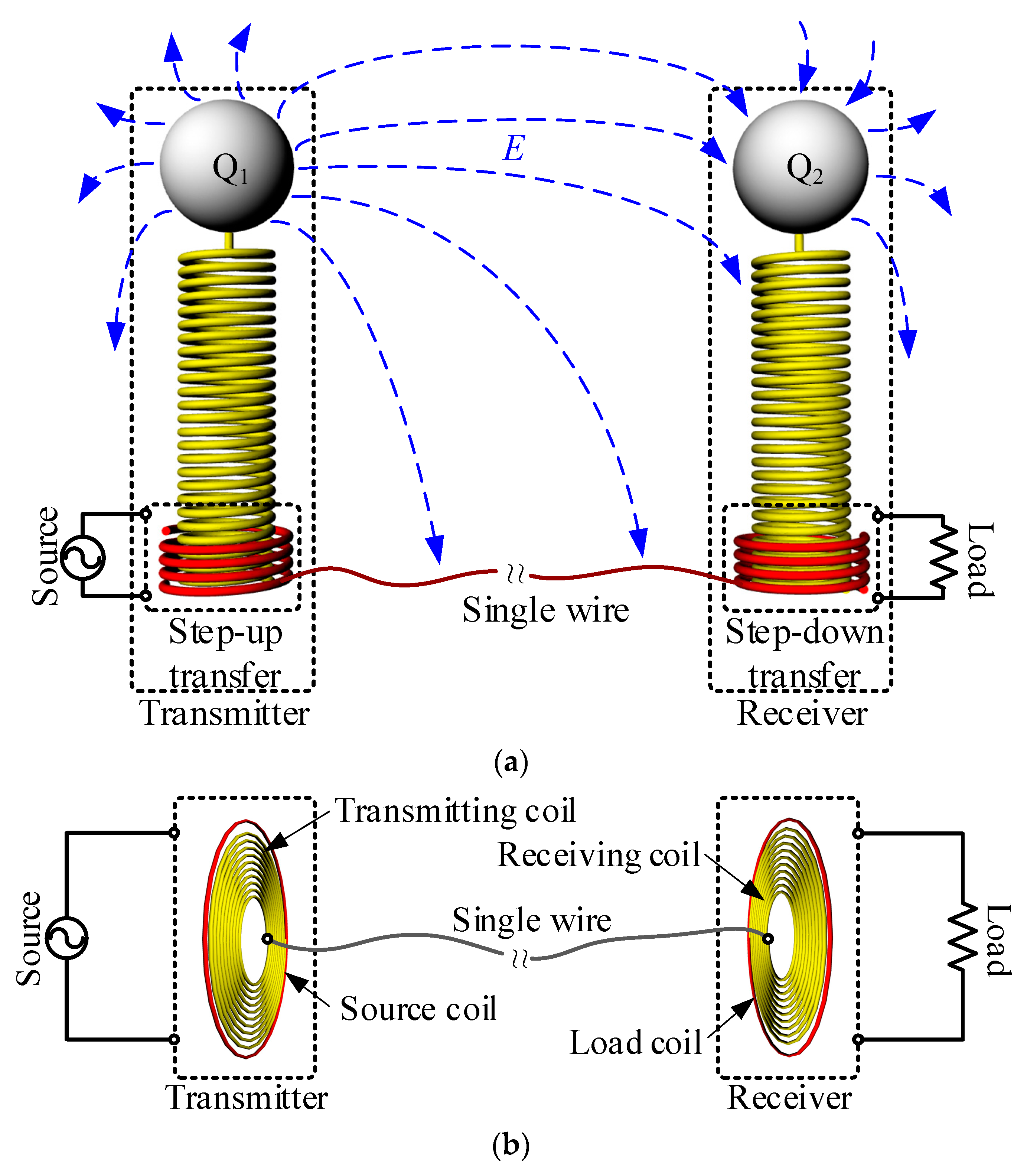
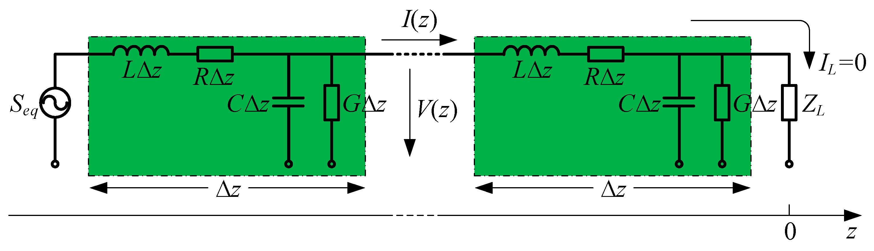
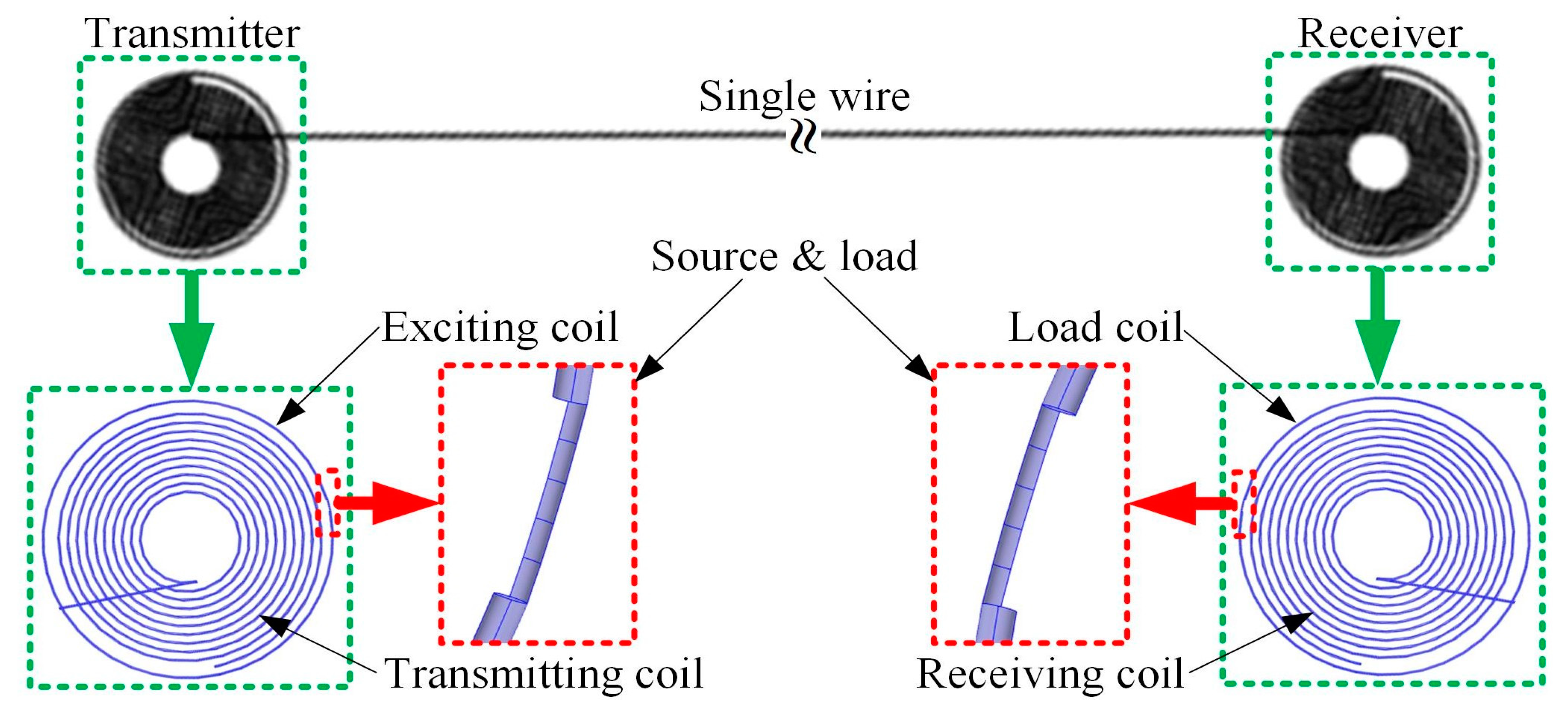
2. Structures of Single-Wire Power Transfer Systems

Figure 1a shows the structure of a single-wire power transfer system evolved from Tesla’s WPT system [22]. The system contains a source, transmitter, receiver and load. The transmitter includes a step-up transfer and metal conductor Q1. The receiver comprises a step-down transfer and metal conductor Q2. The source supplies power for the whole system. When the transmitter obtains the power from the source, there will be time-varying electromagnetic field at Q1. The power is transferred from the transmitter to the receiver through coupling the electric field between Q1 and Q2, which is the first path of this system. The receiver provides power for the load. The single wire is the second path. The first and second path form a closed loop for power transfer [23,24].
The coupled electric field strength decreases as distance increases between transmitter and receiver. As a result, power cannot be transferred effectively through Q1 and Q2. The numbers of turns of transfers are very large and there are two metal conductors causing a large volume of the transmitter and receiver. Besides, the voltage obviously increases at the metal conductors because of the large numbers of turns. On the one hand, such a high voltage breaks peripheral air down, leading to the discharge phenomenon and, on the other hand, the high-frequency time-varying electromagnetic field generated by the high voltage affects the normal operation of the surrounding equipment.
The power supply requirements for WSNs cannot be satisfied by the system shown in Figure 1a because of the large volume and high voltage. Therefore, the single-wire power transfer system for WSNs is improved on the basis of Figure 1a and is shown in Figure 1b. The metal conductors are removed and the coils are spiral planes, which can realize miniaturization. The source coil and load coil are connected to source and load, respectively. One end of the transmitting coil and receiving coil are connected to the single wire. The other ends of the transmitting coil and receiving coil are open ended. The parameters of the transmitter and receiver are completely identical, including the number of turns, inside radii, pitches, wire diameters and radians of coils.
The path generated by metal conductors does not exit when the metal conductors are removed. Figure 2 is the equivalent circuit of the single-wire power transfer system, which is a transmission line terminated in an open circuit. Seq is the equivalent source including the source and transmitter in Figure 1b. ZL is the equivalent load including the load and receiver in Figure 1b. ∆z is per-unit-length quantities. R and L are series resistance and inductance per unit length of the single wire. G and C are shunt conductance and capacitance per unit length generated by the single wire and the surrounding environment. According to the transmission line theory, the voltage and current on the line are:
V ( z ) = 2 V 0 cos ( β z )
I ( z ) = 2 j V 0 Z 0 cos ( β z )
where β = ω(LC)1/2. The voltage reflection coefficient, Γ, is:
Γ = Z L Z 0 Z L + Z 0
where Z0 is the characteristic impedance. There is only one wire in the single-wire power transfer system. So, the single-wire power transfer system is a transmission line terminated in an open circuit and ZL = ∞ because of the open circuit at terminal. Dividing the numerator and denominator of (3) by ZL and allowing ZL→∞ show that the voltage reflection coefficient for this case is Γ = 1. The single-wire power transfer system in Figure 1b uses the standing wave principles to transfer power. The coils are used to increase voltage which can decrease the losses of the single wire. The frequency of the system is determined by the equation f = 1/(2π(L1C1)1/2), where L1 is the total inductance including the series inductance of single wire S and the inductance of coils, C1, is the total capacitance including shunt capacitance of single wire C, the distributed capacitance between the coils and single wire and between each turn of the coils. Frequency and impedance are determined by L1 and C1. This is the circuit analysis of the single-wire power transfer system. From the perspective of electromagnetic field propagation, the electromagnetic field generated by the transmitter propagates to the receiver by the single wire. It is an oriented power transfer and the single wire plays an important role in guiding and binding the electromagnetic field. The electromagnetic field propagates in all directions and covers a large far-field range if there is no single wire, which leads to the low efficiency of the receivers. This is the reason why the efficiency of WPT via the coupled electromagnetic field decreases as the transmission distance increases.

3. Simulation Analysis

The feasibility of the single-wire power transfer method for WSNs is verified by simulations in this section. Figure 3 shows the simulation model of the single-wire power transfer system, where there is a transmitter on the left and a receiver on the right and they are connected to the single wire. The number of turns of the source coil and load coil is one and the transmitting coil and receiving coil have 10 turns. The inside radii, pitches of the coils and the wire diameters are 60 mm, 10 mm and 1.06 mm, respectively. The radians of the source and load coil and transmitting and receiving coil are the same size. The feasibility is verified through simulating directivity and multi-loads based on the characteristics of WSNs.

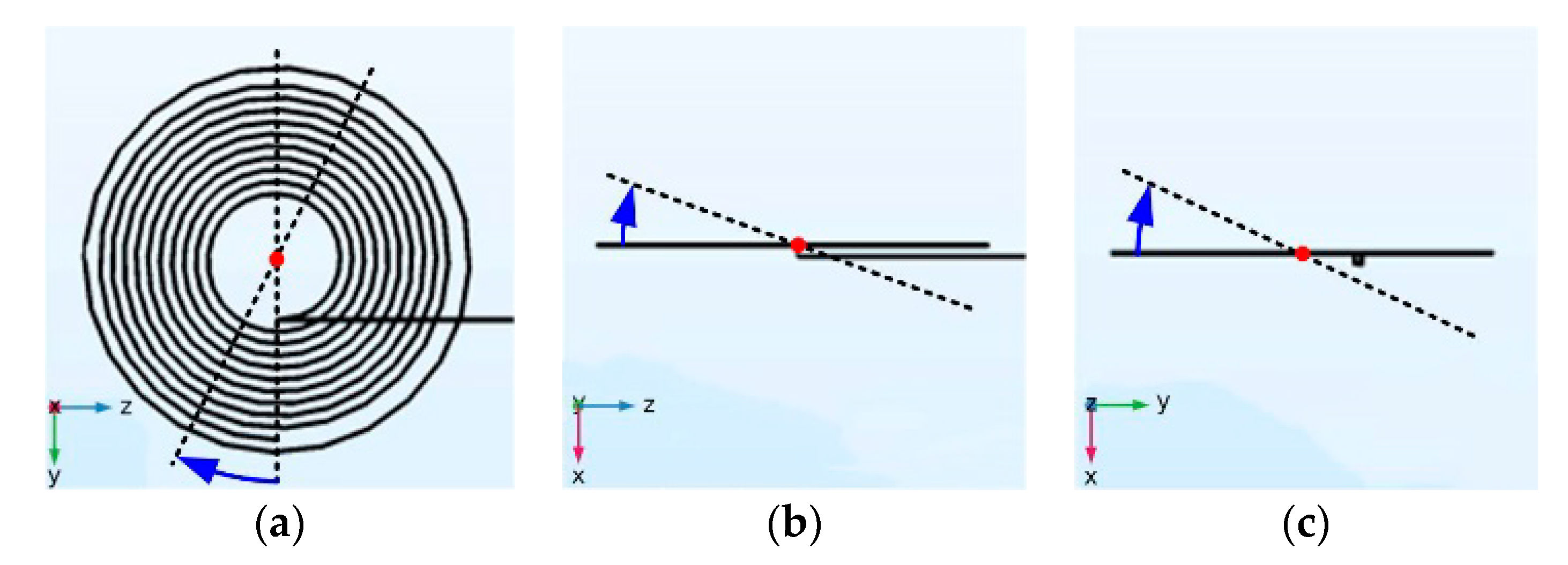
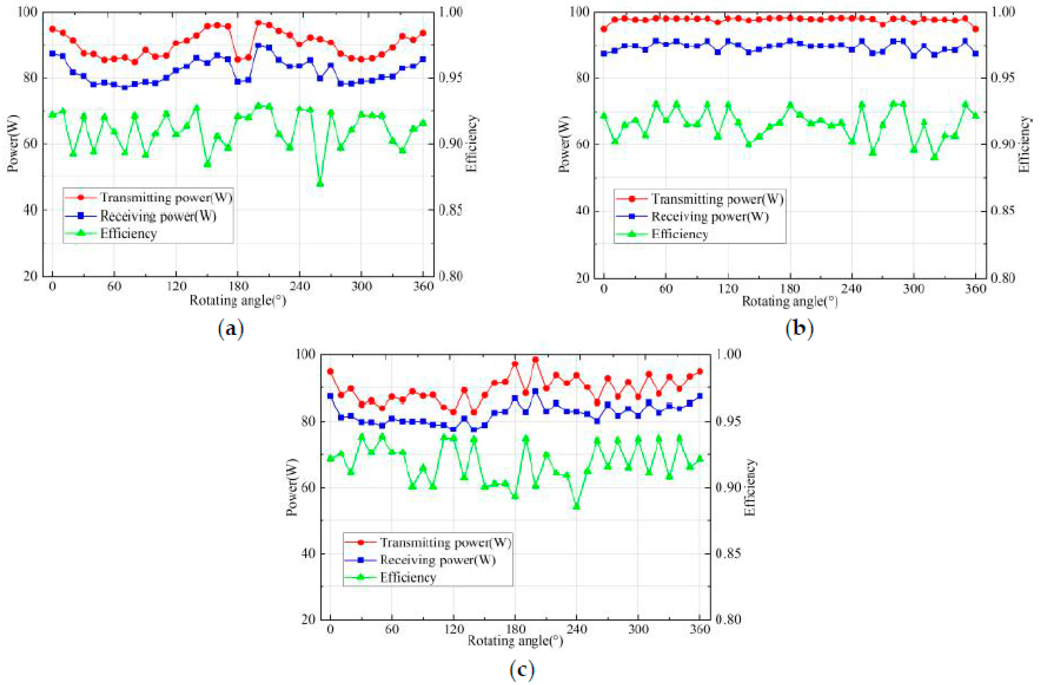
3.1. Directivity Simulations

The transmission distance and frequency of the directivity simulation model are 5 m and 10.55 MHz, respectively. The structure of the single-wire power transfer system is similar to the wireless power transfer system. The only difference is the single wire. So, the frequency of the single-wire power transfer system is close to wireless power transfer system. The rotating directions of the receivers in the single-wire power transfer system are shown in Figure 4. The rotating centers are the centers of the coils and the rotating axes are the axes of the three-dimensional coordinate system. The transmitting power, receiving power and efficiency before rotating are 94.83 W, 87.40 W and 92.16%, respectively. The rotating step and angle are 10° and 360°. The simulation results are shown in Figure 5.
When the rotating axis is the x-axis, as shown in Figure 5a, the difference in values between maximum and minimum transmitting power, receiving power and efficiency are 3.49 W, 4.67 W and 4.02%, respectively. The difference in values of the transmitting power, receiving power and efficiency are 11.27 W, 11.88 W and 4.48% when the rotating axis is the y-axis, shown in Figure 5b. When the rotating axis is the z-axis, the difference in values of the transmitting power, receiving power and efficiency in Figure 5c are 15.30 W, 11.29 W and 5.3%.
The transmitting power, receiving power and efficiency all change slightly from the original values. Besides, the frequency of system also changes slightly. The frequency is determined by L1 and C1 from Section 2. L1 and C1 change slightly when routing receivers lead to the changes in frequency. Considering the errors in simulation systems, it can be assumed that there is no directivity in the single-wire power transfer system. In addition, the power and efficiency can also satisfy WSNs. It is a favorable condition for powering WSNs with the characteristics of distribution and self-organization.
There is no directivity in the single-wire power transfer system when receivers rotate over each axis independently in the above simulations. Rotating over three axes is explored for further verification. Angle of 45° and 135° are chosen as the rotating angles over each axis because the rotating combination is too much over three axes and there are eight combinations. The simulation results are shown in Table 1. The results show that the transmitting power, receiving power and efficiency all still change slightly when the receivers rotate over three axes. The simulation results further verify that there is no directivity in the single-wire power transfer system.

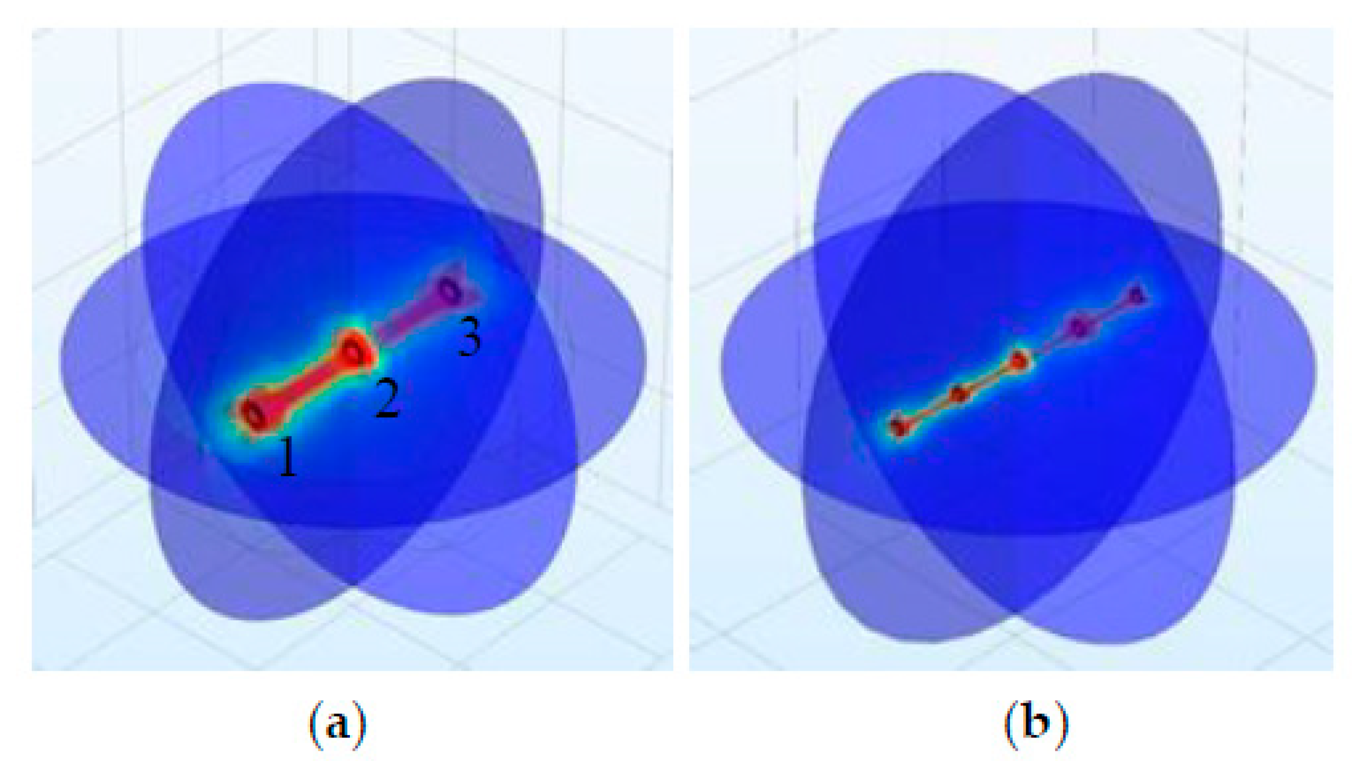
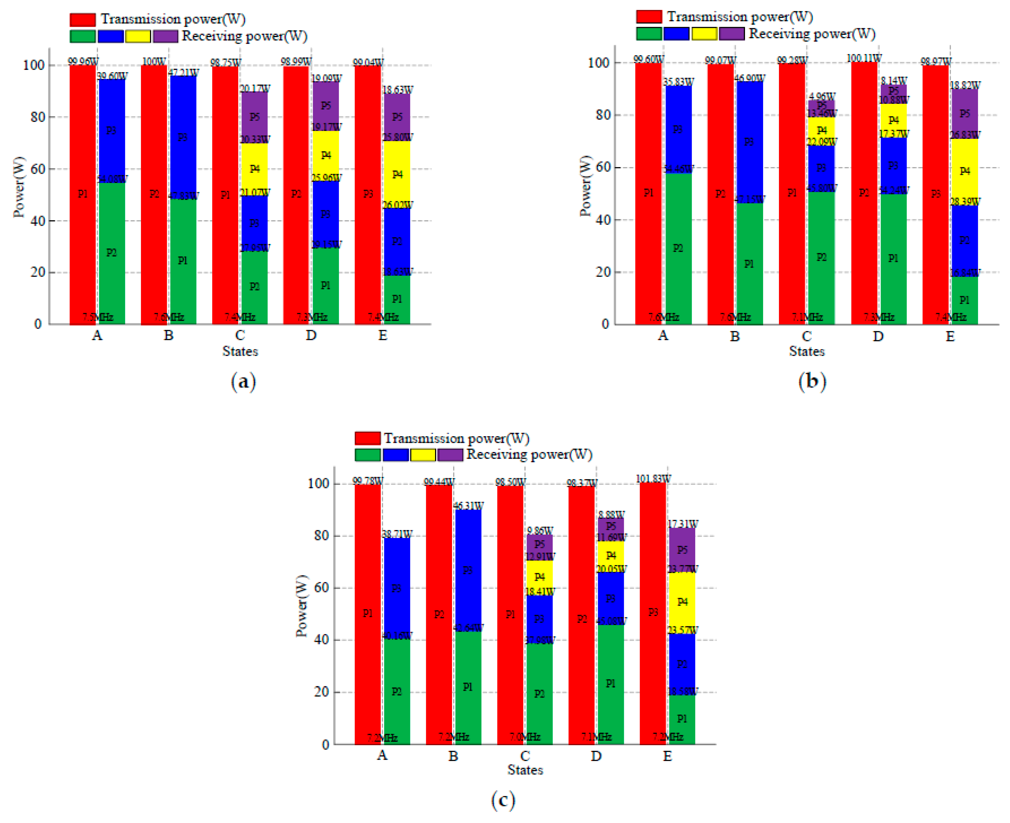
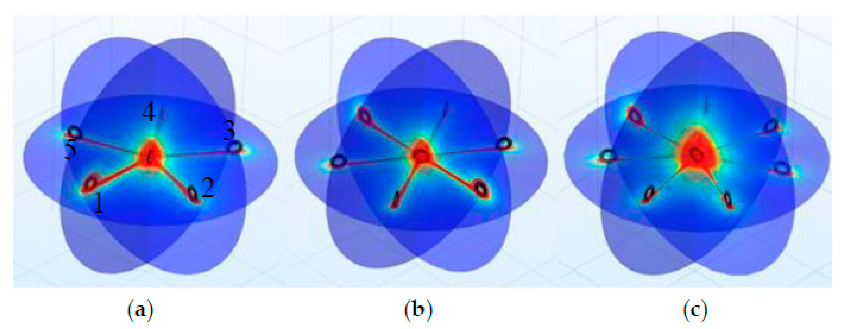
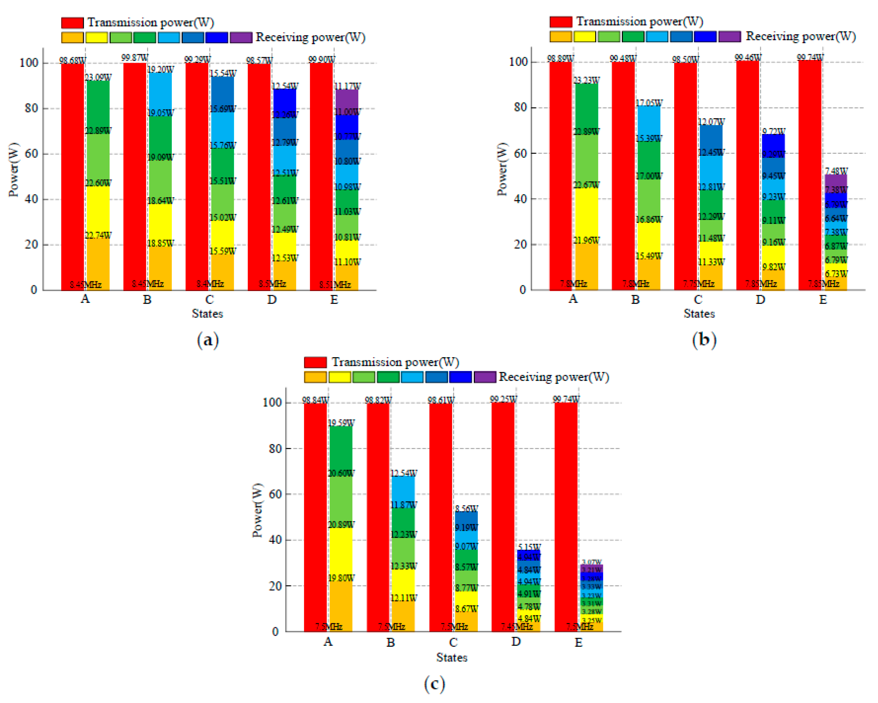
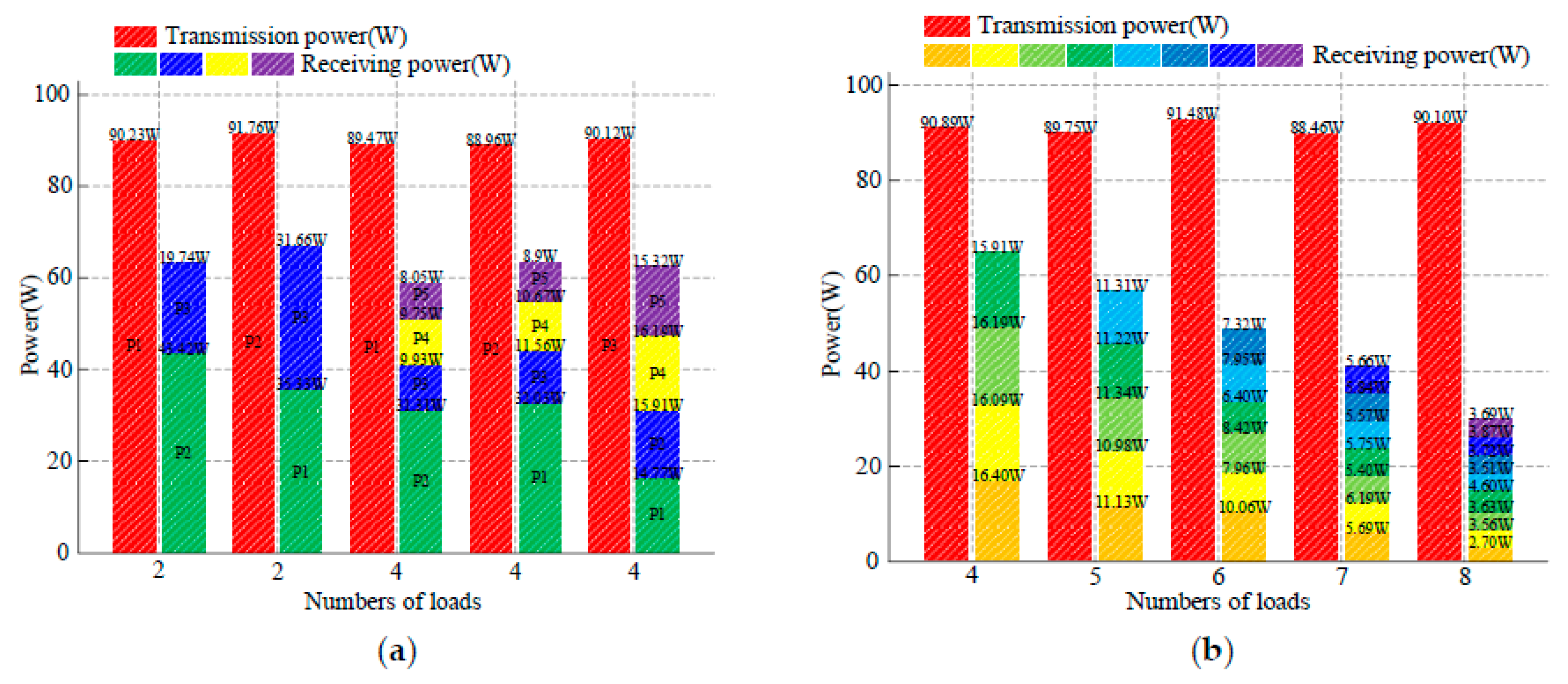
3.2. Multi-Load Simulations

The single-wire power transfer system includes a chained system and emanant system according to the multi-load distribution forms. Identical coils are connected to the single wire in turn in chained systems (Figure 6). The coil positions are numbered in turn in chained systems. The receiving power of each receiver can be observed and compared by changing the positions of transmitters to analyze power distribution. Taking a two-load chained system as an example, the coil positions are numbered 1, 2 and 3 and the transmitter can be placed in position 1 and 2 because of symmetry, as shown in Figure 6a. Other chained systems are consistent with this.
Figure 6 shows the electromagnetic field distribution of chained systems, where the transmitters are in the middle. There are electromagnetic fields in the receivers and they are symmetric, as seen from the color distribution. It can be considered preliminarily that the receivers can receive power and the power may be symmetric. For chained systems at transmission distances of 2 m, 5 m and 10 m, the specific values of transmitting and receiving power are shown in Figure 7. State A and B are two-load chained systems. State C, D and E are four-load chained systems. The red boxes represent transmitting power and other colored boxes represent receiving power. The frequencies of different chained systems are shown in the figures. PX in the figures represents the positions of coils, such as P1 in state A of a 2 m chained system, which means the transmitter is in position 1. The total efficiencies of states A-E in 2 m systems are 93.72%, 95.04%, 90.65%, 94.32% and 89.94%, respectively. The total efficiencies in 5 m systems are 90.65%, 94.93%, 86.94%, 90.53% and 91.83%, respectively. The total efficiencies in 10 m systems are 79.04%, 89.45%, 80.37%, 87.12% and 81.73%, respectively. The receiving power of receivers is obviously different when the transmitters are placed in different positions. However, when the transmitters are in the middle of the system, the receiving power is symmetric. This result is consistent with the above electromagnetic field distribution. Therefore, from the perspective of average power distribution, the transmitters should be placed in the middle as much as possible for the chained multi-load single-wire power transfer systems for WSNs.
In emanant systems, the transmitters are in the center and the receivers surround the transmitters (Figure 8). The receivers are numbered counter-clockwise. Taking a five-load emanant system as an example, the structure of the system and the numbers of coils are shown in Figure 8a. The receiving power of each receiver can be observed and compared by changing the numbers of receivers and transmission distances to analyze power distribution. The electromagnetic field distributions of emanant systems are shown in Figure 8. There are electromagnetic field in the receivers and they are almost identical, as seen from the color distribution. The electromagnetic field strength of transmitters is obviously higher than that of receivers. It can be considered preliminarily that the receivers can receive power and the receiving power may be identical.
The specific values of transmitting and receiving power with different numbers of receivers and different transmission distances are shown in Figure 9. State A, B, C, D and E are four-, five-, six-, seven- and eight-load emanant systems, respectively. The red boxes represent transmitting power and other colored boxes represent receiving power. The frequencies of different emanant systems are shown in the figures. The total efficiencies of state A-E in 2 m systems are 92.54%, 94.95%, 93.78%, 89.00% and 87.75%, respectively. The total efficiencies in 5 m systems are 91.77%, 82.22%, 73.53%, 66.14% and 56.21%, respectively. The total efficiencies in 10 m systems are 81.83%, 61.81%, 53.57%, 34.66% and 26.03%, respectively. The receiving power of receivers is almost identical when the transmission distances are fixed. The receiving power of receivers is average and this result is consistent with the abovementioned electric field distribution. When the transmission distances are set as variables, the receiving power of receivers decreases as the transmission distances increase. Comprehensively, the chained systems and emanant systems can be used in WSNs, but the emanant systems are better than chained systems from the perspective of average power distribution. The node distributions are complex in practical WSNs. The combination forms of chained systems and emanant systems can be used to make complex WSNs which can give full play to their characteristics and make the single-wire power transfer method more suitable for powering WSNs.

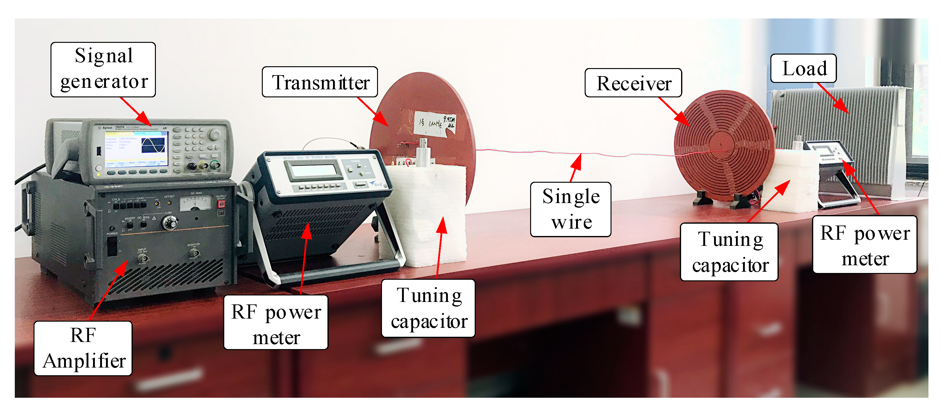
4. Experiment Results

The characteristics of single-wire power transfer were analyzed from the perspective of simulations in Section 3. In this section, we describe an experimental platform that was built to verify the feasibility of the single-wire power transfer method for powering WSNs. The experimental platform is shown in Figure 10. The signal generator was connected to the RF amplifier to provide high-frequency power for the single-wire power transfer system. The coils in the experiments were connected to adjustable capacitors for tuning. The transmitting and receiving powers were measured by the RF power meters.

4.1. Comparative Experiments

In order to verify that single-wire power transfer systems are more suitable for powering WSNs compared with WPT systems, comparative experiments were first conducted. In the comparative experiments, the coils were the same as in the simulations. The number of turns of the source coil and load coil was one and the transmitting coil and receiving coil had 10 turns. The inside radii, pitches of the coils and the wire diameters were 60 mm, 10 mm and 1.06 mm, respectively. The transmitting power was fixed and the transmission distances were set from 5 cm to 50 cm. The transmission efficiencies for different transmission distances are shown in Table 2.
As the transmission distance increased, the efficiencies of the single-wire power transfer system were maintained above 80%. The transmission efficiencies of the WPT system gradually decreased as the transmission distance increased. When the transmission distance was more than 20 cm, the transmission efficiencies decreased to below 50%. Single-wire power transfer systems can maintain high and stable transmission efficiency within a certain distance. Meanwhile the transmission distance has great influence on the transmission efficiency in WPT systems. So, single-wire power transfer systems are more suitable for powering WSNs.

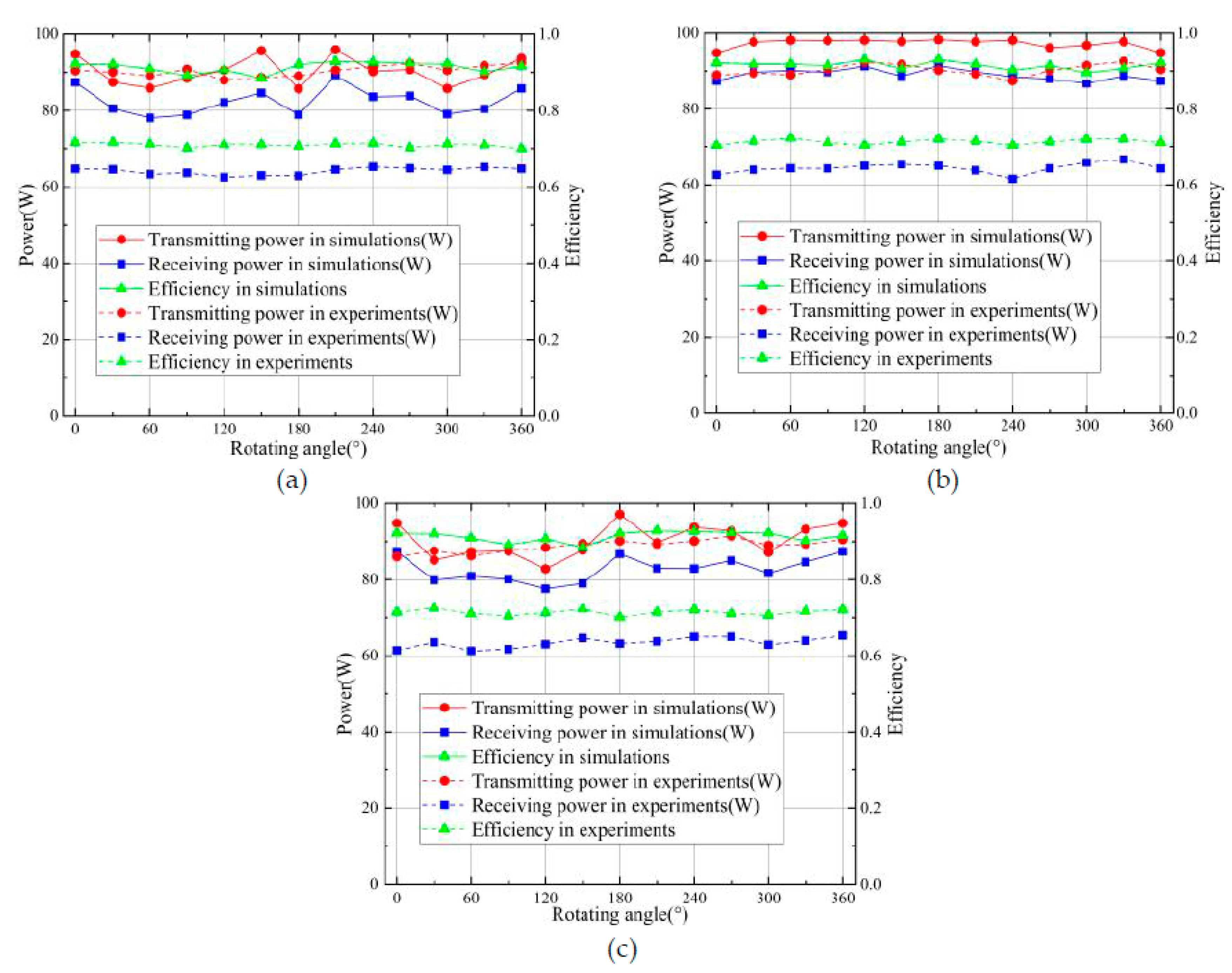
4.2. Directivity Experiments

The transmission distance was set to 5 m in the directivity experiments. The coils were consistent with those of the comparative experiments and simulations. There were dial plates under the receivers, which were used to determine rotating angles. The transmitting and receiving powers were measured by power meters.
The transmitting power and receiving power were first recorded when the rotating angle was 0°. Then the receivers were rotated and the transmitting and receiving powers of the systems were recorded. The routing angles were from 0° to 360° and the routing step was 30°. The transmitting power, receiving power and efficiencies of different rotating axes of simulations and experiments are shown in Figure 11. The dashed lines are experimental results and the solid lines are simulation results. The efficiencies of the experiments were lower than those of the simulations and the efficiencies were constant during rotating. The results show that the receiving power was constant during rotating. There was no directivity over each axis in the single-wire power transfer system. To further verify directivity, rotating experiments over three axes were conducted. The experimental results and simulation efficiencies are shown in Table 3. The efficiencies of the experiments were also lower than those of the simulations. The efficiencies were still constant and there was no directivity. The experimental results are consistent with those of the simulations.

4.3. Multi-Load Experiments

Two-load and four-load chained systems and four-load, five-load, six-load, seven-load and eight-load emanant systems were built based on the simulations in Section 3. The coils were consistent with those of the comparative experiments and simulations. The transmission distance was 5 m. In this section, the influence on the system caused by the positions of transmitters and receivers, the numbers of the loads and the power distribution among loads were explored.
The experimental results of multi-load chained systems are shown in Figure 12a. The positions of transmitters and the numbers of receivers were changed synchronously in the multi-load chained experiments. When the transmitters were in the center positions of the chained systems, the receiving power was basically identical. For example, the receiving power was 31.66 W and 35.33 W when the transmitter was in position 2 of the two-load chained system and the receiving power was 15.32 W, 16.19 W, 14.77 W and 15.91 W when the transmitter was in position 3 of the four-load chained system. As a result, the receiving power can be distributed evenly in chained systems when the transmitters are in the center positions. When the transmitters are not in the center positions of chained systems, the total receiving power on the left side of the transmitters is equal to that on the right side. Taking the four-load chained system as an example, the receiving power on the left was 32.03 W when the transmitter was in position 2, the receiving power on the right was 11.56 W, 10.67 W and 8.9 W and the total receiving power was 31.13 W.
Besides, the positions of each coil (including transmitters and receivers) were moved freely. The coils were not in a straight line in this case. The transmitting power, receiving power and efficiencies all changed slightly from the original values. The receiving power decreases after a few nodes because the transmission distance increases after a few nodes, leading to an increase in system losses. Generally, the power distribution laws of the chained systems in the experiments were consistent with the simulations.
Figure 12b shows the experimental results of multi-load emanant systems. The numbers of loads are the main variables in the emanant systems. The numbers of loads were changed from four to eight. The receiving power of each receiver was equal because each receiver was connected to the transmitter. Meanwhile, the angles between receivers were changed in the experiments. For example, the angles were 90° when the receivers were symmetric in the four-load emanant system, but the angles were random in this experiment. The results show that the receiving power changed slightly from the original values with the changes of angles between receivers. The transmission efficiencies decreased with the increase in loads. The experimental results of the emanant systems were also consistent with the simulation results.
Table 4 shows the comparison of the simulation and experimental efficiencies of 5 m multi-load systems. The transmission efficiencies of the experiments were lower than those of the simulations. The material of the coils and the single wire is the perfect conductor, as conductivity is infinite and there is no insulating layer of the conductor for the convenience of modeling in simulations. There are no conductor losses or dielectric losses in simulations. However, the material is copper, whose conductivity is very large, but still finite, and there is an insulating layer of copper, making the coils and single wire experience conductor losses and dielectric losses in experiments. Besides, the simulation models are perfect. However, there are many metal objects, such as experimental equipment, in a laboratory. These metal objects are easily exposed to the electromagnetic field generated by single-wire power transfer systems, leading to eddy current losses in metal objects. As a result, the transmission efficiencies of experiments are lower than those of the simulations.

5. Conclusions

In this paper, the single-wire power transfer method for WSNs is studied and the feasibility of this method is verified. The conclusions are summarized as follows:
  • A novel single wire power transfer system structure is utilized because of the large volume and high voltage of the single-wire power transfer system that evolved from Tesla’s WPT system. Metal conductors are removed and coils are miniaturized in the novel structure. This structure can improve system flexibility and reduce system complexity under the premise of ensuring transmitting power and efficiency.
  • The directivity of the system is studied based on the characteristics of WSNs. The transmitting power, receiving power and efficiency all change slightly from the original values with the rotating of receivers. The rotating of receivers does not affect the systems. There is no directivity in single-wire power transfer systems.
  • The characteristics of multi-loads are also studied. The multi-load distribution forms can be chained and emanant. The distribution forms are flexible. These two forms all can distribute power evenly. This feature lays the foundation for powering WSNs.
  • Harvesting energy from nature and wireless power transfer technology are the main solutions to powering WSNs. However, these two methods have the problem of low efficiency. The load of mobile devices carrying transmitters is limited in the wireless power transfer method. This method is limited to charging one node at a time. However, the single-wire power transfer method still could maintain high efficiencies in a certain range and charge multiple nodes at a time. As a result, the single-wire power transfer method is more suitable for WSNs compared with other solutions.
  • The feasibility of the single-wire power transfer method for WSNs is proved in this paper. The structure of the single-wire power transfer system is not genuine wireless power transfer because of the existence of the single wire. Besides, the system performance can still be improved, such as efficiency. Medium replacement of the single wire can make this method more suitable for WSNs. The system performance can be improved from the perspective of system parameters and system structure. The electromagnetic losses of the single wire can be decreased by changing system parameters, such as the frequency and radius of the single wire. The coupling losses between the coils and single wire can be decreased by novel structures, such as a conical horn. Medium replacement and the improvement of system performance are the two most significant research directions of the single-wire power transfer method in the future.

Author Contributions

The paper was written by Y.L. (Yang Li), R.W., Y.-J.Z. and Y.L. ( Yao Li) and revised by X.N., J.L. and J.M. The project was conceived, planned and supervised by Y.L.(Yang Li) All authors have contributed to the editing and proofreading of this paper. All authors have read and agree to the published version of the manuscript.

Funding

This research was funded by the National Natural Science Foundation of China under Grant 51877151, Grant 51577133, Grant 51677132 and in part by the Program for Innovative Research Teams at the University of Tianjin under Grant TD13-5040.

Conflicts of Interest

The authors declare no conflict of interest.

References

  1. Luigi, A.; Antonio, I.; Giacomo, M. Wireless sensor networks: A survey. Comput. Netw. 2010, 54, 2787–2805. [Google Scholar]
  2. Rashid, M.M.; Gondal, I.; Kamruzzaman, J. Mining Associated Patterns from Wireless Sensor Networks. IEEE Trans. Comput. 2015, 64, 1998–2011. [Google Scholar] [CrossRef]
  3. Han, G.; Jiang, J.; Zhang, C.; Duong, T.Q.; Guizani, M.; Karagiannidis, G.K. A Survey on Mobile Anchor Node Assisted Localization in Wireless Sensor Networks. IEEE Commun. Surv. Tutor. 2016, 18, 2220–2243. [Google Scholar] [CrossRef]
  4. Akyildiz, I.F.; Su, W.; Sankarasubramaniam, Y.; Cayirci, E.J. A survey on sensor networks. IEEE Commun. Mag. 2002, 40, 102–114. [Google Scholar] [CrossRef] [Green Version]
  5. Sambo, D.W.; Forster, A.; Yenke, B.O.; Sarr, I.; Journal, P.D. Wireless Underground Sensor Networks Path Loss Model for Precision Agriculture (WUSN-PLM). IEEE Sens. J. 2020, 20, 5298–5313. [Google Scholar] [CrossRef]
  6. Prapti, G.; Kam, N.; Instrumentation, P.W. Measurement, Wireless Sensor Network System for Landslide Monitoring and Warning. IEEE Trans. Instrum. Meas. 2018, 68, 1210–1220. [Google Scholar]
  7. Arroyo, P.; Herrero, J.; Suárez, J.; Lozano, J.J. Wireless Sensor Network Combined with Cloud Computing for Air Quality Monitoring. Sensors 2019, 19, 691. [Google Scholar] [CrossRef] [PubMed] [Green Version]
  8. Tong, B.; Wang, G.; Zhang, W.; Wang, C. Node Reclamation and Replacement for Long-Lived Sensor Networks. Ieee Transactions on Parallel and Distributed Systems. IEEE Trans. Parallel Distrib. Syst. 2011, 22, 1550–1563. [Google Scholar] [CrossRef]
  9. Fujimoto, T.; Uto, S.; Ishizuka, Y.; Fujishima, T. Energy Storage Solution for Wireless Sensor Network Used in Bridge Surface Corrosion Monitoring. Electron. Lett. 2019, 55, 1186–1188. [Google Scholar] [CrossRef]
  10. Yue, X.; Kiely, J.; Gibson, D.; Drakakis, M.E. Charge-Based Supercapacitor Storage Estimation for Indoor Sub-mW Photovoltaic Energy Harvesting Powered Wireless Sensor Nodes. IEEE Trans. Ind. Electron. 2019, 67, 2411–2421. [Google Scholar] [CrossRef] [Green Version]
  11. Tang, M.; Guan, Q.; Wu, X.; Zeng, X.; Zhang, Z.; Yuan, Y. A high-efficiency multidirectional wind energy harvester based on impact effect for self-powered wireless sensors in the grid. Smart Mater. Struct. 2019, 28. [Google Scholar] [CrossRef]
  12. Jellard, S.C.J.; Pu, S.-H.; Chen, S.; Yao, K. Water droplet impact energy harvesting with P(VDF-TrFE) piezoelectric cantilevers on stainless steel substrates. Smart Mater. Struct. 2019, 28. [Google Scholar] [CrossRef]
  13. Saravanakumar, K. Microbial fuel cell–based self-powered biosensor for environment monitoring in IoT cloud framework. Concurr. Comp. Pract. E 2019, 31, e5165. [Google Scholar] [CrossRef]
  14. Yang, P.; Zi, L.; Zhang, W.; Qiao, D. Prolonging Sensor Network Lifetime Through Wireless Charging, IEEE Real-time Systems Symposium. In Proceedings of the 31st IEEE Real-Time Systems Symposium, San Diego, CA, USA, 30 November–3 December 2010. [Google Scholar]
  15. Xie, L.; Shi, Y.; Hou, Y.T.; Sherali, H.D. Making Sensor Networks Immortal: An Energy-Renewal Approach with Wireless Power Transfer. IEEE/ACM Trans. Netw. 2012, 20, 1748–1761. [Google Scholar] [CrossRef]
  16. Covic, G.A.; Boys, J.T. Modern Trends in Inductive Power Transfer for Transportation Applications. IEEE J. Emerg. Sel. Top. Power Electr. 2013, 1, 28–41. [Google Scholar] [CrossRef]
  17. Song, J.; Zhao, X.; Wu, X.; Xuan, R. High rectification efficiency direct bandgap Ge1−xSnx Schottky diode for microwave wireless power transfer. Appl. Phys. A 2019, 125. [Google Scholar] [CrossRef]
  18. Jin, K.; Zhou, W. Wireless Laser Power Transmission: A Review of Recent Progress. IEEE Trans. Power Electr. 2018. [Google Scholar] [CrossRef]
  19. Meng, M.; Kiani, M. Design and Optimization of Ultrasonic Wireless Power Transmission Links for Millimeter-Sized Biomedical Implants. IEEE Trans. Biomed. Circuits Syst. 2017, 11, 98–107. [Google Scholar] [CrossRef] [PubMed]
  20. Johnson, J.; Basha, E.; Detweiler, C. Charge selection algorithms for maximizing sensor network life with UAV-based limited wireless recharging. In Proceedings of the IEEE Eighth International Conference on Intelligent Sensors, Melbourne, Australia, 2–5 April 2013. [Google Scholar]
  21. Griffin, B.; Detweiler, C. Resonant wireless power transfer to ground sensors from a UAV. In Proceedings of the IEEE International Conference on Robotics & Automation, St Paul, MN, USA, 14–19 May 2012. [Google Scholar]
  22. Tesla, N. Apparatus for Transmitting Electrical Energy. U.S. Patent 1119732, 1 December 1914. [Google Scholar]
  23. Shu, X.; Zhang, B. Single-Wire Electric-Field Coupling Power Transmission Using Nonlinear Parity-Time-Symmetric Model with Coupled-Mode Theory. Energies. Energies 2018, 11, 532. [Google Scholar] [CrossRef] [Green Version]
  24. Chen, X.; Chen, J.; Li, G.; Mu, X.; Chen, Q. Electric-field-coupled single-wire power transmission—Analytical model and experimental demonstration. In Proceedings of the 19th International Symposium on Power Electronics (Ee), Novi Sad, Serbia, 19–21 October 2017. [Google Scholar]
Figure 1. Structures of single-wire power transfer systems (a) evolved from Tesla’s wireless power transfer (WPT) system and (b) improved in this paper.
Energies 13 05182 g001
Figure 2. Equivalent circuit of the single-wire power transfer system.
Energies 13 05182 g002
Figure 3. Simulation model of the single-wire power transfer system.
Energies 13 05182 g003
Figure 4. Rotating axes of receivers for (a) x-axis, (b) y-axis and (c) z-axis.
Energies 13 05182 g004
Figure 5. Simulation results of the single-wire power transfer system with rotating receivers when the (a) rotating axis is the x-axis, (b) rotating axis is the y-axis and (c) rotating axis is the z-axis.
Energies 13 05182 g005
Figure 6. Electromagnetic field distribution of chained systems with (a) two loads and (b) four loads.
Energies 13 05182 g006
Figure 7. Specific values of transmitting and receiving power of chained systems, transmission distances are (a) 2 m, (b) 5 m and (c) 10 m.
Energies 13 05182 g007
Figure 8. Electromagnetic field distribution of emanant systems with (a) five loads, (b) six loads and (c) seven loads.
Energies 13 05182 g008
Figure 9. Specific values of transmitting and receiving power of emanant systems, transmission distances are (a) 2 m, (b) 5 m and (c) 10 m.
Energies 13 05182 g009
Figure 10. Experimental platform of the single-wire power transfer system.
Energies 13 05182 g010
Figure 11. Experimental results of directivity when the (a) rotating axis is the x-axis, (b) rotating axis is the y-axis and (c) rotating axis is the z-axis.
Energies 13 05182 g011
Figure 12. Experimental results of multi-load systems for (a) 5 m chained system and (b) 5 m emanant system.
Energies 13 05182 g012
Table 1. Simulation results of directivity when receivers rotate over three axes.
X-AxisY-AxisZ-AxisTransmitting Power (W)Receiving Power (W)Efficiencies
45°45°45°86.5178.5190.75%
135°87.3978.3889.69%
135°45°93.6785.7791.57%
135°97.5788.4990.69%
135°45°45°98.3291.3992.95%
135°94.8387.4092.16%
135°45°82.7577.4893.63%
135°85.7180.1893.55%
Table 2. Results of comparative experiments.
Transmission Distances (cm)Efficiencies of Single-Wire Power Transfer SystemEfficiencies of WPT System
584.65%78.05%
1083.16%74.16%
1584.47%69.40%
2080.54%41.58%
2582.23%30.63%
3083.79%18.28%
3584.87%10.25%
4085.01%6.17%
4584.36%3.53%
5083.79%1.86%
Table 3. Experimental results of directivity when receivers rotate over three axes.
X-AxisY-AxisZ-AxisTransmitting Power in Experiments (W)Receiving Power in Experiments (W)Efficiencies in ExperimentsEfficiencies in Simulations
45°45°45°90.1264.5871.66%90.75%
135°87.9862.5371.07%89.69%
135°45°90.4564.2671.04%91.57%
135°89.2663.7871.45%90.69%
135°45°45°92.5666.6872.04%92.95%
135°86.2961.2971.03%92.16%
135°45°90.1763.1770.06%93.63%
135°90.5665.2872.08%93.55%
Table 4. Comparison of simulation efficiencies and experimental efficiencies of 5 m multi-load systems.
Multi-Load Distribution FormsNumbers of LoadsSimulation EfficienciesExperimental Efficiencies
Chained multi-load systems2 (P1)90.65%70.00%
2 (P2)94.93%73.01%
4 (P1)86.94%65.99%
4 (P2)90.53%71.00%
4 (P3)91.83%69.01%
Emanant multi-load systems491.77%71.06%
582.22%62.37%
673.53%52.59%
766.14%45.33%
856.21%32.50%

