Article

Numerical Study on the Thermal Performance of a Single U-Tube Borehole Heat Exchanger Using Nano-Enhanced Phase Change Materials

1
Information and Communication Technologies vs. Climate Change Group, Institute for Information and Communication Technologies, Universitat Politècnica de València, Camino de Vera S/N, 46022 Valencia, Spain
2
Faculty of Mechanical Engineering, Babol Noshirvani University of Technology, Babol 47148-71167, Iran
*
Author to whom correspondence should be addressed.
Energies 2020, 13(19), 5156; https://doi.org/10.3390/en13195156
Submission received: 21 August 2020 / Revised: 25 September 2020 / Accepted: 30 September 2020 / Published: 3 October 2020
(This article belongs to the Special Issue Shallow Geothermal Energy 2021)

Abstract

:
To investigate the impacts of using nano-enhanced phase change materials on the thermal performance of a borehole heat exchanger in the summer season, a three-dimensional numerical model of a borehole heat exchanger is created in the present work. Seven nanoparticles including Cu, CuO, Al2O3, TiO2, SiO2, multi-wall carbon nanotube, and graphene are added to the Paraffin. Considering the highest melting rate and lowest outlet temperature, the selected nano-enhanced phase change material is evaluated in terms of volume fraction (0.05, 0.10, 0.15, 0.20) and then the shape (sphere, brick, cylinder, platelet, blade) of its nanoparticles. Based on the results, the Paraffin containing Cu and SiO2 nanoparticles are found to be the best and worst ones in thermal performance improvement, respectively. Moreover, it is indicated that the increase in the volume fraction of Cu nanoparticles could enhance markedly the melting rate, being 0.20 the most favorable value which increased up to 55% the thermal conductivity of the nano-enhanced phase change material compared to the pure phase change material. Furthermore, the blade shape is by far the most appropriate shape of the Cu nanoparticles by considering about 85% melting of the nano-enhanced phase change material.

1. Introduction

Presently, due to extreme environmental pollution and energy shortage around the world, the exploitation of renewable energies has become more vital. Geothermal energy is one of the renewable energies that can be used, specifically by means of coupling to ground source heat pump (GSHP) systems. GSHP system provides heating and cooling of buildings through the ground heat exchanger (GHE) which usually appears in horizontal and vertical configurations. Since the vertical GHE, also named borehole heat exchanger (BHE), needs less land for installation and has wide applicability and better performance than the horizontal GHE, it has been comprehensively investigated in recent years [1].
To improve the thermal performance of the BHEs, various approaches have been taken such as geometry improvements [2,3], the use of new materials for pipe, backfill or grout, and working fluid [1,4]. Quaggiotto et al. [5] studied two types of BHEs including coaxial BHE and double U-tube BHE. Based on the comparison made, heat transfer in the coaxial BHE was higher than the double U-tube BHE both in cooling and heating operating modes. Serageldin et al. [6] investigated experimentally and numerically the use of oval cross-section pipes instead of the circular cross-section pipes used in the BHE in the presence of underground water. It was concluded that a BHE with oval cross-section pipes has the potential to decrease the installation costs and increase the thermal performance of the BHE. In a thermal response test (TRT) conducted by Sapinska-Sliwa et al. [7] for three types of BHEs, for instance, single U-tube, double U-tube, and coaxial BHE, the last configuration was found to be the best one in achieving the effective thermal conductivity of the ground. In another study, carried out experimentally and numerically by Janiszewski et al. [8], a single U-tube BHE was used to inject thermal energy into the surroundings. It was proven that a higher thermal conductivity of the pipe and backfill as well as a larger pipe distancing and pipe radius are essential for improving the borehole thermal energy storage (BTES) system efficiency. A review article concerning a variety of nanofluids that can be applied as working fluids in the BHE was conducted by Patil et al. [9]. It was concluded that nanofluids can enhance the thermal performance of the BHE when it operates at higher temperatures, as the higher the temperature the better the thermal conductivity of nanofluids. In an experimental study done by Cao et al. [10], it was shown that a BHE with a steel pipe can have superior thermal performance and lower thermal resistance compared to a BHE with a polyethylene pipe. Li et al. [11] evaluated experimentally single U-tube and double U-tube BHEs at different depths and concluded that increasing the depth of the pipe results in greater thermal performance of BHEs in both summer and winter seasons.
One type of the backfill materials that is applied in the BHE is phase change material (PCM). The PCMs are generally categorized into organic, inorganic, hygroscopic, and solid-solid materials. The organic PCMs such as Paraffin have been widely used in the BTES systems to provide energy for the heat pumps because of their high TES capacity. In addition, organic PCMs are found to be beneficial for GSHP applications. To use such materials as backfill and to improve the thermal performance of the BHEs, their low thermal conductivity must increase, as the higher the thermal conductivity of the backfill the superior the heat transfer from the working fluid to the surrounding ground. Hence, a variety of methods are carried out to tackle this problem [4]. Wang et al. [12] studied numerically the use of a mixture of lauric acid and n-decanoic acid as backfill in a single U-tube BHE. The results showed that the thermal interference radius and the temperature difference between inlet and outlet could decrease and increase by 26% and 67% respectively, compared to the soil as backfill. Lei and Dai [13] investigated theoretically the influence of using a mixture of lauric acid and capric acid as a backfill on the thermal performance of a coaxial BHE. The results indicated that the differences between the inlet and outlet temperatures of the working fluid are 0.24 °C when using soil backfill and 0.08 °C for the PCM backfill at the end of the cooling operation. A numerical study on applying shape-stabilized PCM (SSPCM), a mixture of lauric acid and decanoic acid, as backfill in a single U-tube BHE was carried out by Li et al. [14,15]. Based on their results, the heat exchange rate and thermal interference radius for the BHE backfilled with SSPCM could be 1.37 and 0.9 times of that for crushed stone concrete as a backfill. The effects of three types of PCM backfill including acid, enhanced acid, and Paraffin RT27 on the thermal performance of a single U-tube BHE is evaluated numerically by Qi et al. [16]. The results demonstrated that PCM backfills have a smaller thermal interference radius than soil backfill. A numerical investigation of using SSPCM and microencapsulated Paraffin as backfill in a single U-tube BHE was conducted by Chen et al. [17]. It was concluded that SSPCM improves the thermal performance of the BHE compared to microencapsulated Paraffin, thanks to its higher thermal conductivity. It was also found that the use of the SSPCM backfill is beneficial where the effect of underground water is negligible. Besides, Chen et al. [18] examined the impact of different melting temperatures of PCM backfill on the BHE thermal performance and selected 20.4 °C as the best melting temperature which led to improving the cooling operation of the system. A study on the thermal performance of a single U-tube BHE when it is backfilled with salt hydrate PCM was done by Zhang et al. [19]. The numerical results showed that when the PCM was used as a backfill in the BHE, the temperature differences of the working fluid at the inlet and outlet after 6 h of cooling operation increased compared to the corresponding temperature differences in the BHE containing a conventional backfill which led to enhancing the heat transfer rate and system efficiency in the summer. Yang et al. [20] studied both numerically and experimentally the use of a mixture of lauric acid and decyl acid for cooling operating and oleic acid for heating operating as backfill material in a single U-tube BHE. According to the results, PCM backfills reduce almost 88% and 86% of the thermal interference radius for heating operating and cooling operating compared to soil backfill, respectively. An increase of 28% and 9.4% are found in the heat exchange rate per meter of borehole depth for heating and cooling operating, respectively, when using PCM backfills instead of soil backfill.
Please note that there have been also a few articles regarding the use of PCM (microencapsulated PCM) as backfill in the Horizontal GHE [21,22,23]. Moreover, PCM has had other applications in GSHP systems. Zhang et al. [19] presented a new type of BHE named underground thermal battery in which both BHE and PCM (forming a ring inside the borehole) were immersed in a water tank. In a theoretical study of Rabin and Korin [24], Paraffin was used in the form of a ring as TES inside/outside the borehole. Benli and Durmus [25,26] experimentally investigated the integration of a Horizontal GHE with a TES system containing salt hydrate PCM for heating of a greenhouse. A mixture of microencapsulated Paraffin and soil was examined as TES combined with a Horizontal GHE both experimentally and numerically [27]. Eslami-Nejad and Bernier [28] evaluated numerically the use of a PCM-sand mixture as a ring inside the borehole. In a numerical investigation conducted by Zhu et al. [29], hydrate sodium sulfate was applied as TES which was integrated with a BHE. Jeon et al. [30] studied numerically the incorporation of a panel form of PCM as TES with a Horizontal GHE. In a numerical study carried out by Alkhwildi et al. [31], a BHE combined with a TES system containing salt hydrate PCM. The application of microencapsulated PCM slurry as a working fluid in a tree-shaped BHE was evaluated numerically by Pu et al. [32].
Furthermore, there is another type of PCM called nano-enhanced PCM (NEPCM) that is created by dispersing the nanoparticle into a pure PCM. Khodadadi and Hosseinizadeh [33] were the first scholars who investigated the addition of nanoparticles into PCM and proved that the created NEPCM has better thermal conductivity and higher TES capacity than the conventional PCMs. NPCM has brought many benefits to buildings [34], heat exchangers [35], TES [36], solar systems [37], and electronic devices [38]. Kalaiselvam et al. [34] dispersed experimentally Al2O3 and Al nanoparticles to a PCM comprised of n-hexadecane and n-tetradecane which were applied in an advanced building for cooling operation. Their results indicated 4.97% and 12.97% reductions in the solidification time when using Al and Al2O3 nanoparticles, respectively, in comparison with the pure PCM. The impact of adding CuO nanoparticles to RT50 PCM placed inside a shell and tube heat exchanger was carried out numerically by Pahamli et al. [35]. It was concluded that the melting time decreases by 11.6% and 4.56% provided that the volume fractions of the nanoparticles are 4% and 2%, respectively, resulting in superior thermal performance of the heat exchanger. Ramakrishnan et al. [36] added experimentally graphene nanoparticles to a PCM consisted of expanded perlite and RT27 which were used as TES. According to the results, both melting and solidification time decrease by 33% compared to the pure PCM, due to an increase of 49% in the thermal conductivity of the PCM when applying graphene with 1% by weight. An experimental investigation of adding graphene oxide, TiO2, and CuO nanoparticles to the Paraffin used in a solar still was conducted by Rufuss et al. [37]. The results showed the increments of 101%, 25%, and 29% in the thermal conductivity of the PCM at the presence of graphene oxide, TiO2, and CuO nanoparticles, respectively, which led to the higher production of freshwater. In another study, the use of NEPCM made of Paraffin wax as PCM and multi-wall carbon nanotube (MWCNT) as nanoparticles in an electronic chipset was examined experimentally by Farzanehnia et al. [38]. The studied NEPCM was found to extend the time of electronic board operation and decrease the time of the cooling process by 6%.
However, based on the previous works concerning NEPCMs [39,40,41] and to the best of the authors’ knowledge, to this day, no scholar has studied the application of NEPCMs as backfill in the BHE which indicates the significance of this study. Therefore, the novelty of the present article is the numerical simulation of NEPCMs in a single U-tube BHE. Accordingly, in the first section of the present study, seven types of NEPCMs are considered and numerical results are compared. Afterward, the selected NEPCM (from the first section) is evaluated in terms of volume fraction and shape of its nanoparticles.

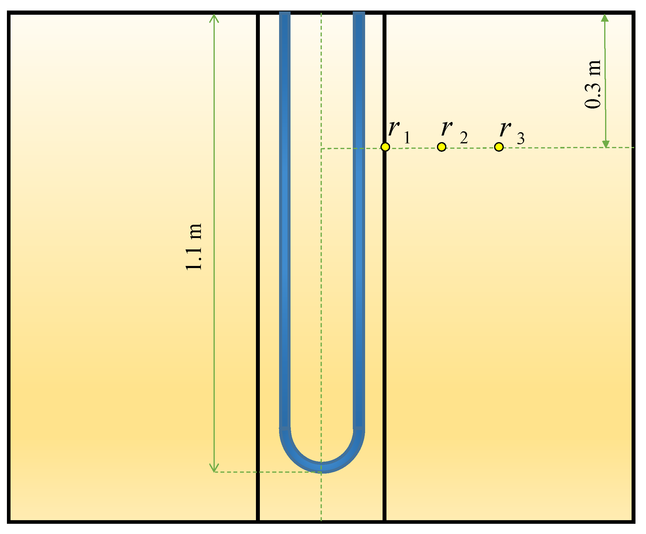
2. Computational Fluid Dynamics Model and Simulation Conditions

In this work, an unsteady 3D model of a BHE is simulated numerically by ANSYS Fluent 18.2 software (see Figure 1). The BHE comprises a single U-tube (copper tube), working fluid (water), backfill (NEPCM), and the surrounding ground. The whole domain is considered to be a cube with a side length of 1.2 m while the length of the U-tube is 1.1 m. The borehole depth and borehole diameter are 1.2 m and 0.06 m, respectively. The distance between centers of two legs of U-tube is 0.0365 m and the outer and inner diameters of U-tube are 0.0065 m and 0.005 m, respectively. The thermo-physical properties of the BHE components are shown in Table 1 and Table 2. Based on a review article conducted by Yang et al. [39], mostly dispersed nanoparticles into the PCMs, such as Cu, CuO, Al2O3, TiO2, SiO2, MWCNT, and graphene, are used as nanoparticles in this study to be added to the Paraffin (n-Octadecane) as the base fluid.
As illustrated in Figure 2, the meshing of the model is provided with high accuracy, especially in the regions near the center of the model as in view of their great influence in the performance of the BHE. Table 3 indicates the grid independence test performed by analyzing four different numbers of elements in terms of outlet temperature of working fluid and liquid fraction after 10 h of BHE operation. Taking into account the balance between precision and calculation speed, a total number of 2,244,671 elements with maximum skewness of 0.79 and minimum orthogonal quality of 0.25 is selected for the numerical simulations. We have applied structured meshing methods for the fluid and the U-tube, and unstructured methods for the backfill and the ground. The BHE works in the summer season for 12 h daily and the inlet temperature of working fluid is considered to be 308.15 K. At the inlet of the model (see Figure 1b), we used a Velocity Inlet boundary condition with a constant value of 0.6 m/s and at the outlet, a Pressure Outlet boundary condition is chosen which can minimize the reverse flows when a backflow condition occurs. The interfaces between the regions are supposed to be temperature-coupled walls and the BHE components are homogeneous, isotropic, and temperature independent. Since the heat transfer fluid inside U-tube is in turbulent regime, we implemented the standard k-epsilon as a turbulence model and the SIMPLE scheme for the velocity-pressure condition. The energy and momentum equations that are discretized spatially by Second-Order Upwind have the Under Relaxation Factors of 1 and 0.7, respectively. The numerical simulation converged once the residuals for momentum, continuity, k, and epsilon were less than 10−3 while the corresponding value for energy was 10−6 (see Table 4).

3. Mathematical Formulation

The nanoparticles and PCM that form NEPCM are in thermal equilibrium and the no-slip condition is considered between them. Other key assumption for this study is to consider the thermo-physical properties of the NEPCM as temperature independent. The density of NEPCM (ρNEPCM) is written as [33]:
ρ N E P C M = ϕ ρ N a n o p a r t i c l e + ( 1 ϕ ) ρ P C M
where ϕ is the volume fraction of the nanoparticles. The specific heat of NEPCM ((Cp)NEPCM) is given by [33]:
( C p ) N E P C M = ϕ ( ρ C p ) N a n o p a r t i c l e + ( 1 ϕ ) ( ρ C p ) P C M ρ N E P C M
The latent heat of NEPCM (LNEPCM) can be expressed as [33]:
L N E P C M = ( 1 ϕ ) ( ρ L ) P C M ρ N E P C M
The dynamic viscosity of NEPCM (μNEPCM) is defined as [33]:
μ N E P C M = μ P C M ( 1 ϕ ) 2.5
The thermal conductivity of NEPCM (kNEPCM) can be calculated by means of the Hamilton–Crosser formula [47], in which in addition to including the thermal conductivities of nanoparticles and PCM as well as the nanoparticle volume fraction, the shape of nanoparticles has also been taken into account, which is as follows:
k N E P C M = k P C M [ k P C M + k N a n o p a r t i c l e + n k P C M + ϕ ( k N a n o p a r t i c l e k P C M ) n ϕ ( k P C M k N a n o p a r t i c l e ) k P C M + k N a n o p a r t i c l e + n k P C M + ϕ ( k P C M k N a n o p a r t i c l e ) ]
where n represents the shape factor of the nanoparticles as shown in Table 5.
To model the phase change process of NEPCM, we used the Enthalpy-Porosity method. The Boussinesq approximation is applied to account for buoyancy effects [33]:
β N E P C M = ϕ ( ρ β ) N a n o p a r t i c l e + ( 1 ϕ ) ( ρ β ) P C M ρ N E P C M
The continuity, momentum, and energy equations are as follows [50,51,52]:
V = 0
V t + V V = 1 ρ N E P C M ( P + μ N E P C M 2 V + ( ρ β ) N E P C M g ( T T r e f ) ) + S
h s e n s t + h l a t t + ( V h s e n s ) = ( k N E P C M ( ρ C p ) N E P C M h s e n s )
where hsens and hlat are the sensible heat enthalpy and latent heat enthalpy, respectively. The total enthalpy is obtained by summation of the enthalpies:
h t o t = h s e n s + h l a t
The sensible heat and latent heat enthalpies can be obtained by Equations (11) and (12) [53,54,55]:
h s e n s = h r e f + T r e f T C p d T = h r e f + C p T r e f T d T
h l a t = i = 1 N λ i L
where λ is the liquid fraction which varies from 0 to 1. λ = 0 indicates that the material is in solid phase, while for λ = 1, the NEPCM is full of liquid. The region where 0 < λ < 1 is considered to be the mushy zone, which acts as a porous region. This parameter is defined as:
λ = { h l a t L = 0       i f       T T s o l i d u s h l a t L = 1       i f       T T liquidus h l a t L = T T s o l i d u s T liquidus T s o l i d u s       i f       T s o l i d u s < T < T liquidus }
In Equation (8), S which is a source term named Darcy’s law damping term is added to the momentum equation:
S = A ( λ ) V
where A ( λ ) = C m u s h ( 1 λ ) 2 / ( λ 3 + ε ) indicates the slow increase of the velocities from zero value in the full solid phase to a finite value in the liquid phase throughout the computational cells at the phase transition occurrence. Cmush is the mushy zone constant fixed at 105 and ε is a small positive quantity (here 0.001) called computational constant which prevents a division by zero [53,54,55].

4. Verification

The verification of the numerical results to the experimental data of Yang et al. [20] is done by comparing the backfill and soil temperatures at different radiuses. The three radiuses of r1, r2, r3 are 0.03 m, 0.19 m, and 0.27 m, respectively, at a depth of 0.3 m (see Figure 3). The BHE works 10 h a day for cooling operation to release the heat to the ground. In the validation, just a mixed acid PCM used as backfill which consists of decyl acid and lauric acid with a mass proportion of 66:34. The other conditions are the same as stated in part 2 of the present study. As shown in Figure 4, the numerical and experimental results display an excellent agreement with the percent errors of less than 5%.

5. Results and Discussion

In the present work, a single U-tube BHE is evaluated numerically by Computational Fluid Dynamics (CFD) software. The aim is to compare different types of NEPCM which are used as backfill in the BHE to allow an optimal selection. Moreover, the chosen NEPCM is analyzed in terms of the volume fraction and shape factor of its nanoparticles.

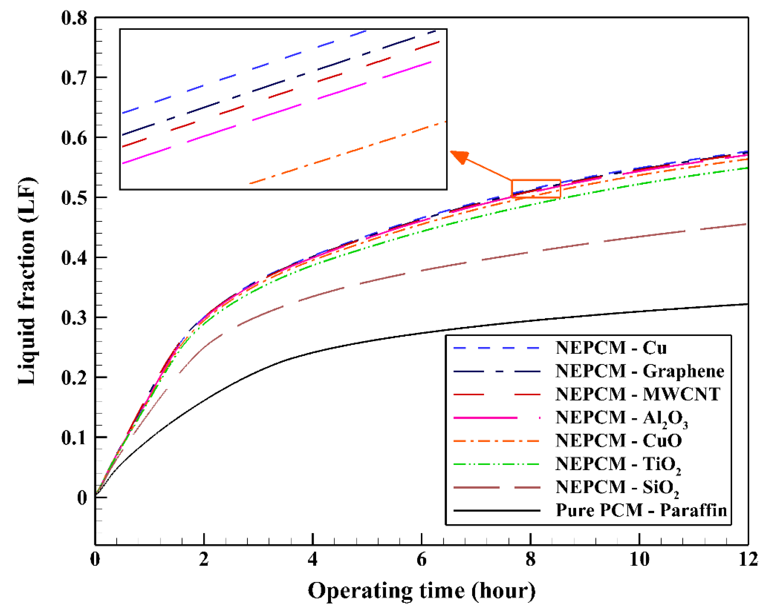
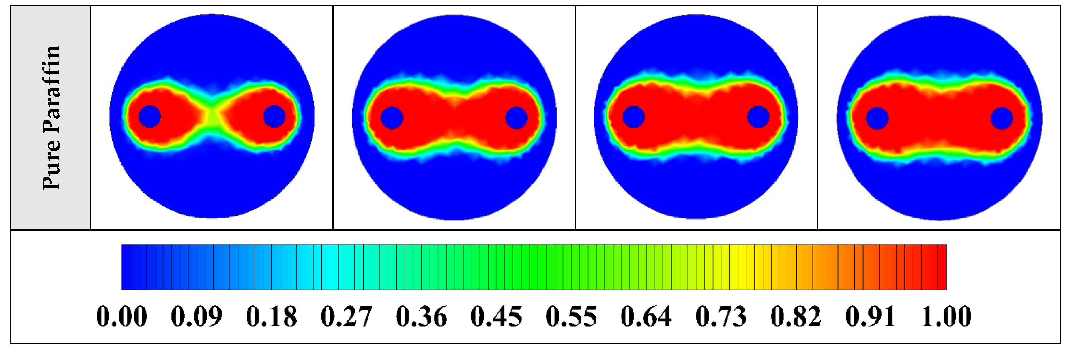
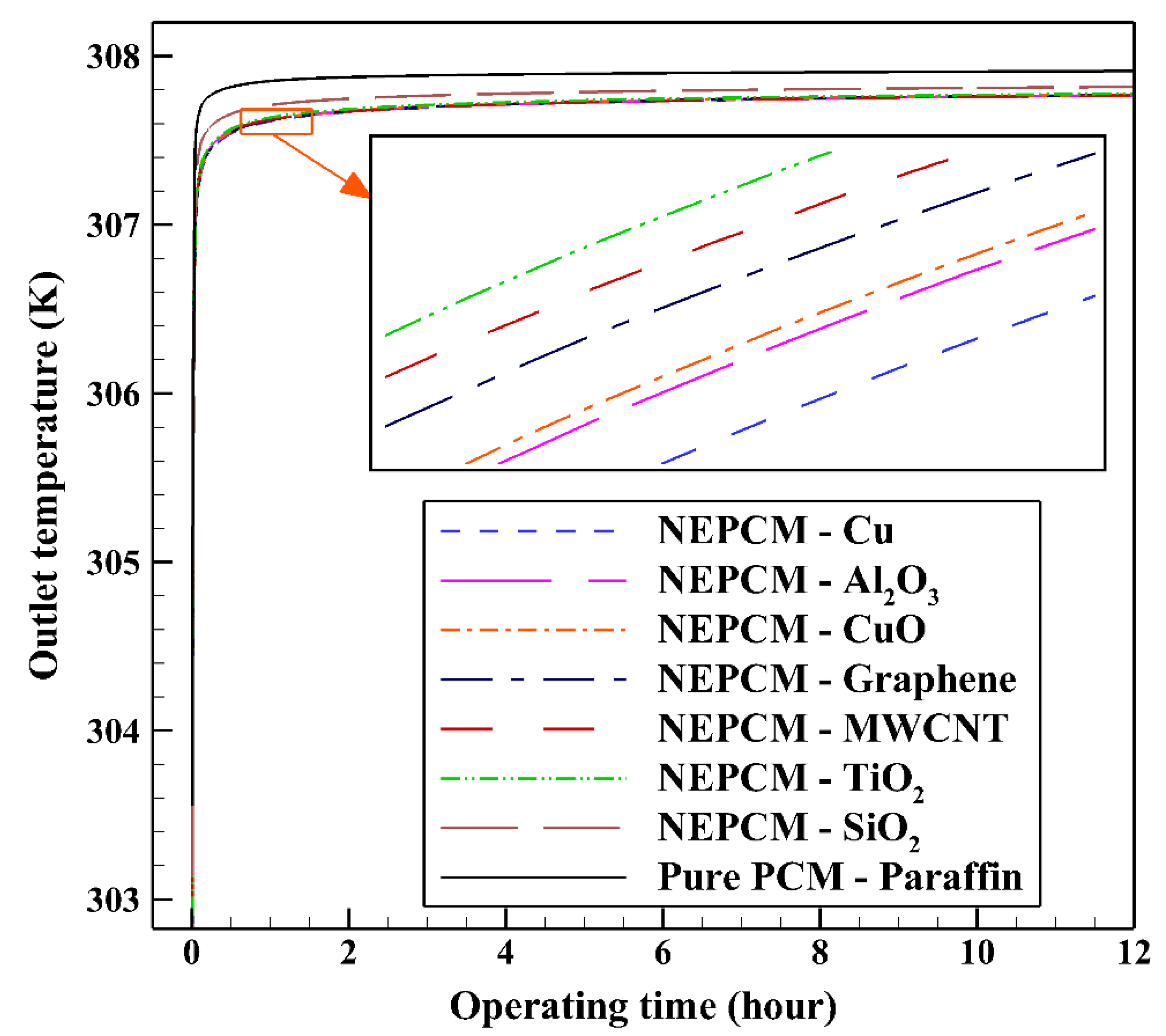
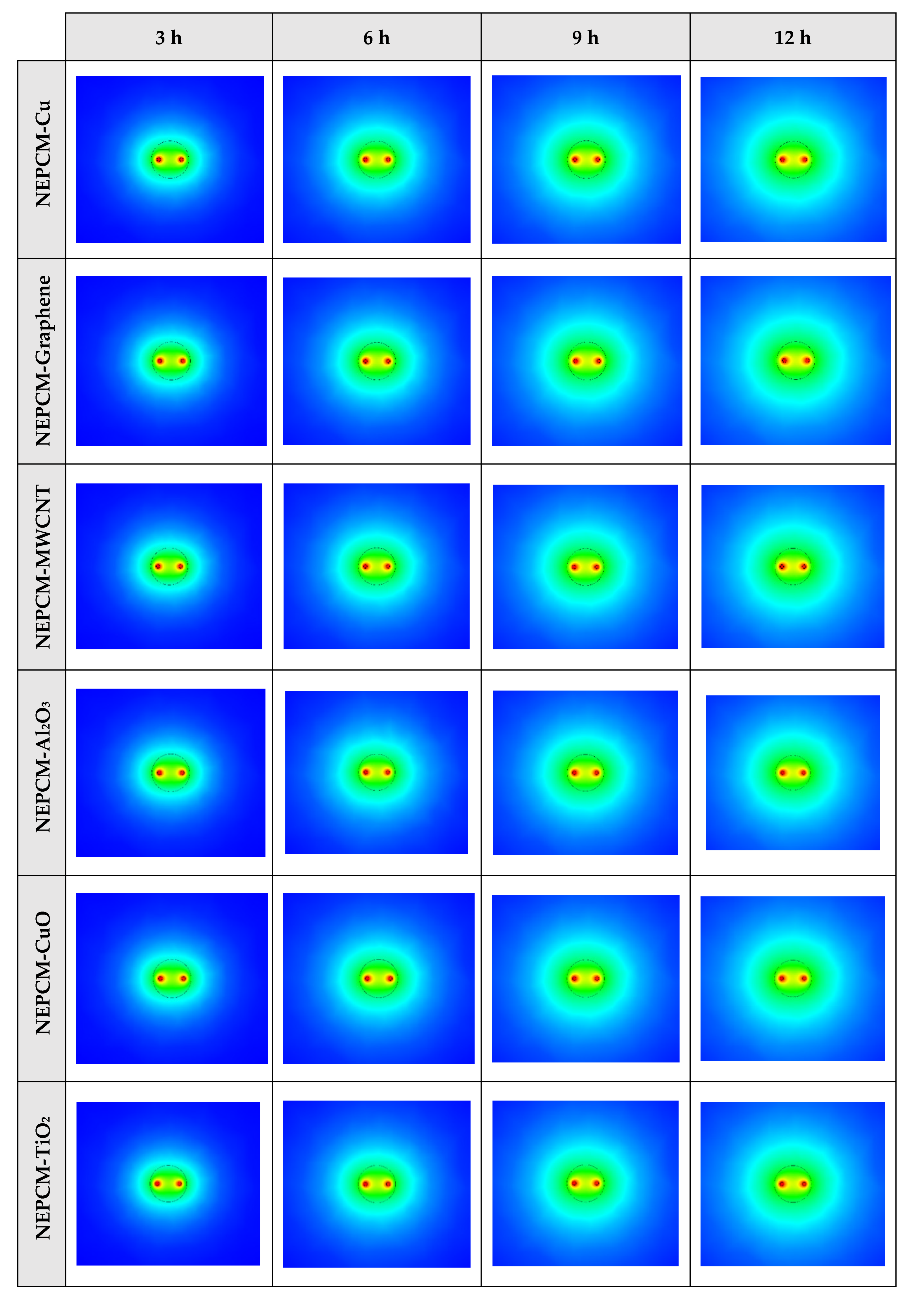
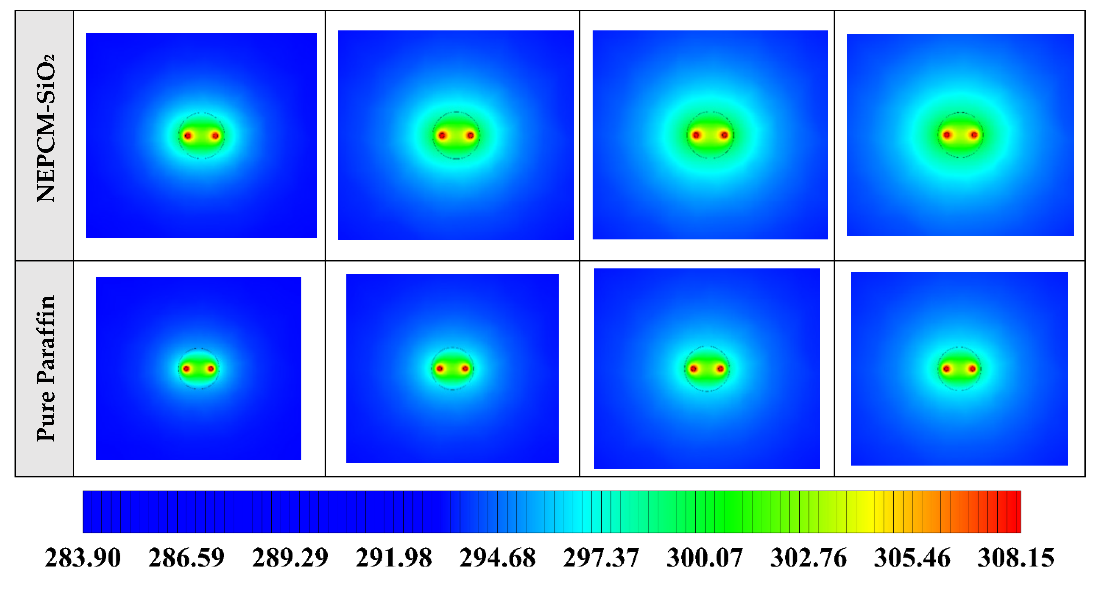
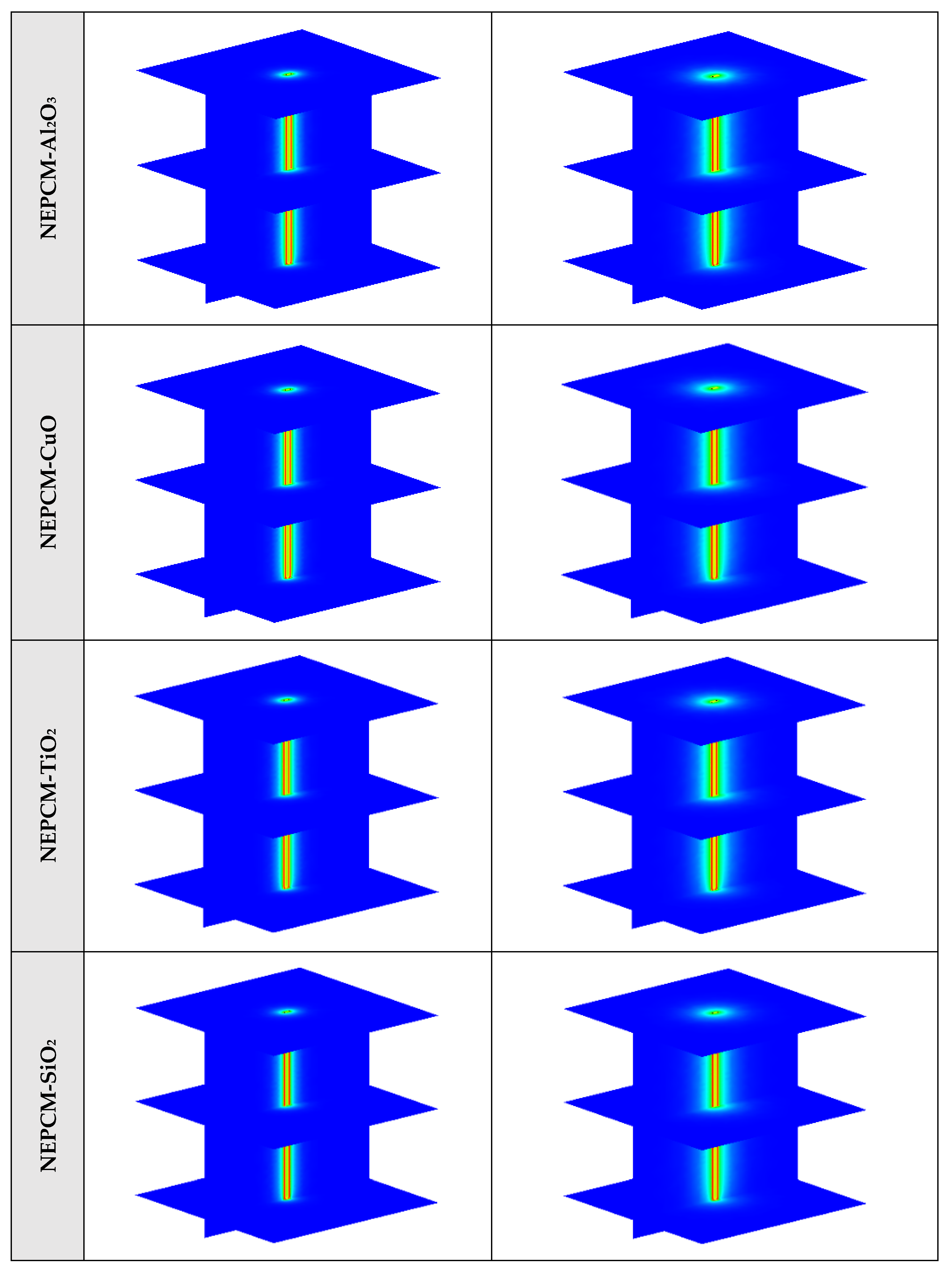
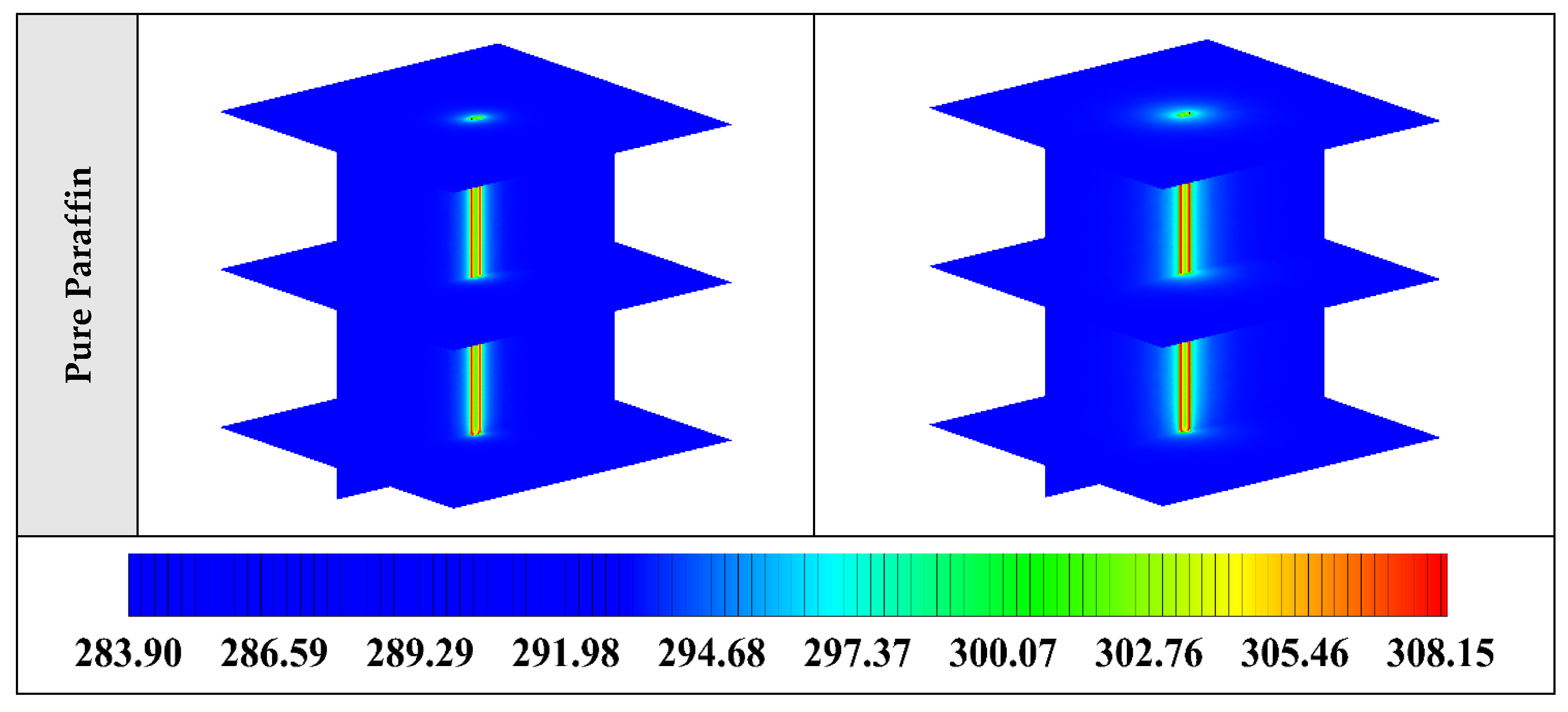
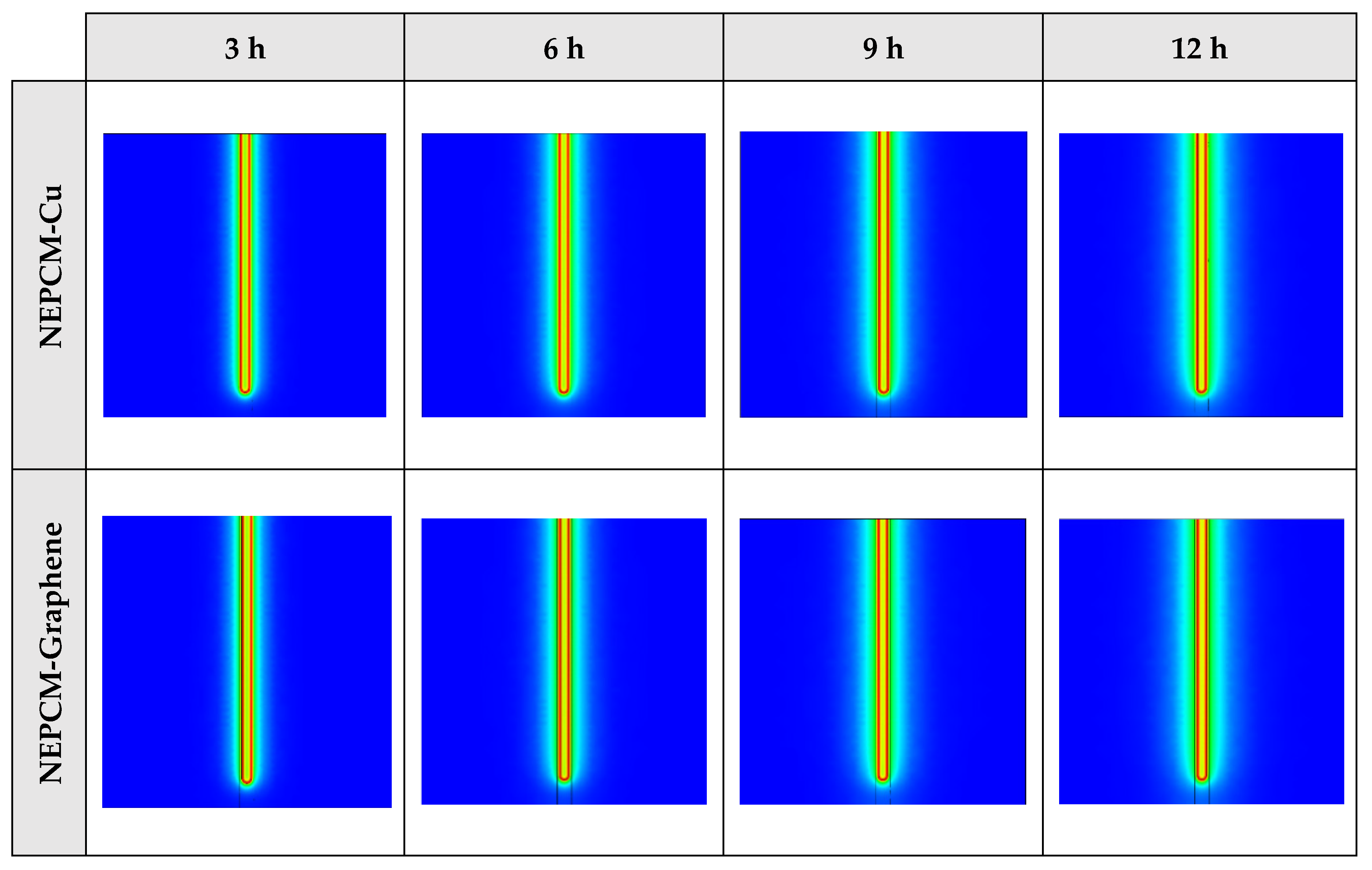
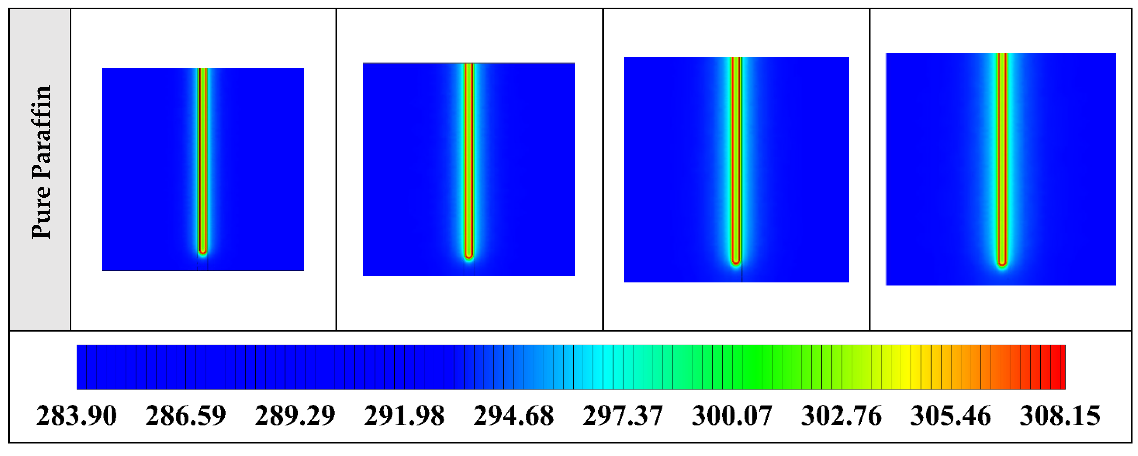
5.1. Impact of Nano-Enhanced Phase Change Material Type

In the first step, comparing various NEPCMs, the nanoparticles are dispersed to the base fluid with volume fraction and shape factor of 20% and 3, respectively. Figure 5 shows the variation of the liquid fraction with operating time when using different NEPCMs. We used Paraffin as the base fluid and added seven kinds of nanoparticles to it to conform the NEPCMs. From this figure, it can be seen that the NEPCM containing Cu nanoparticles is melted better than the other NEPCMs (with the liquid fraction of almost 0.55) and the worst one is found to be the NEPCM containing SiO2 nanoparticles with the liquid fraction close to 0.45. At the end of cooling operation, we can observe the small differences between the liquid fractions of NEPCMs with Cu, graphene, MWCNT, and Al2O3 nanoparticles compared to that for the NEPCMs with CuO, TiO2 and SiO2 nanoparticles. It is worth mentioning that all of the NEPCMs have a significantly higher rate of melting than the pure Paraffin, thanks to the presence of nanoparticles which improve the thermal conductivity of the PCM.
The contours of liquid fraction for various cases at four different times including 3, 6, 9, and 12 h are illustrated in Figure 6. The impact of using NEPCMs instead of pure Paraffin on the melting rate can be realized clearly. Compared to the other materials, in the case with pure Paraffin, the evolution of the contour lines after 6 h from the start of the process is significantly more restricted. In contrast, all NEPCMs present much higher melting rates. Among the studied NEPCMs, the SiO2 nanoparticle material shows the smallest melting rate, although the differences between the rest of compounds are not as marked. The compound using Cu nanoparticle shows a better melting rate with a small difference compared to the others after 12 h.
Considering NEPCM with Cu nanoparticles, the BHE can release more heat to the ground which leads to its superior thermal performance. (see Figure 7). As illustrated, after approximately two hours of BHE operation start, the outlet temperatures of all NEPCMs showed a constant increase which can be explained by the fact that during this time, the temperature difference between the working fluid and other BHE components decreases. Consequently, it prevents the BHE to exchange more heat to the surrounding regions. According to the comparison conducted between seven types of NEPCM, Figure 5 and Figure 7, the addition of Cu nanoparticles to the Paraffin leads to enhancing considerably the thermal performance of the BHE. 2D contours of the temperature distribution of the BHE at various hours of operating using different NEPCMs when ϕ = 0.20, n = 3, and Z = 0 are illustrated in Figure 8.
Figure 8 shows that by using pure Paraffin as PCM, the heat transfer rate between the fluid in the U-tube and the PCM and consequently between PCM and soil is very low. Instead, by using NEPCMs instead of pure PCM, the heat transfer rate increases significantly. Also, among the evaluated NEPCMs, PCM with SiO2 nanoparticle displays the lower heat transfer rate, and based on Figure 8, the differences between the other models are not significant. To realize better the melting process and heat transfer between different BHE components, 3D contours of temperature distribution and 2D contours of temperature distribution (front view, middle plane) of the BHE are presented in Figure A1. (Appendix A) and Figure A4. (Appendix B), respectively. Based on the abovementioned explanations, the NEPCM containing Cu nanoparticles is chosen for further investigation.

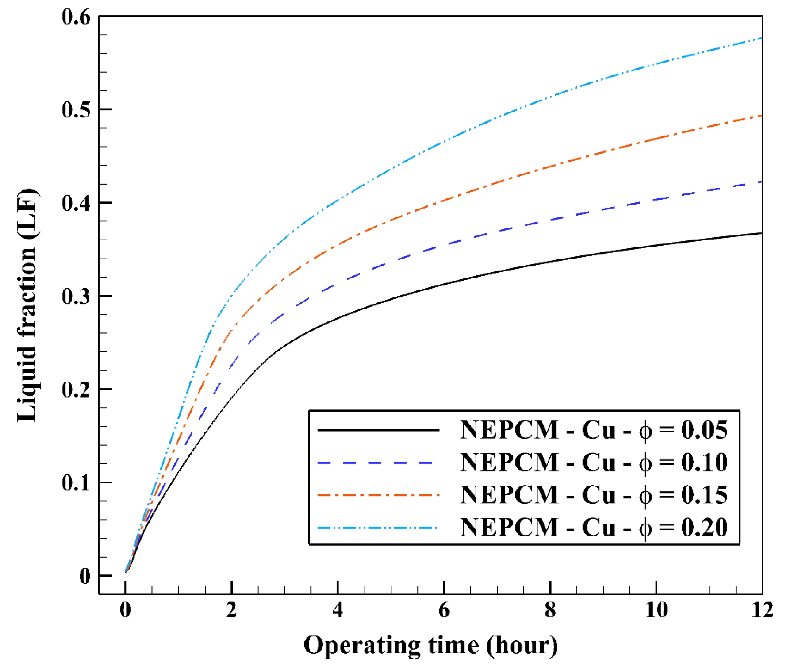
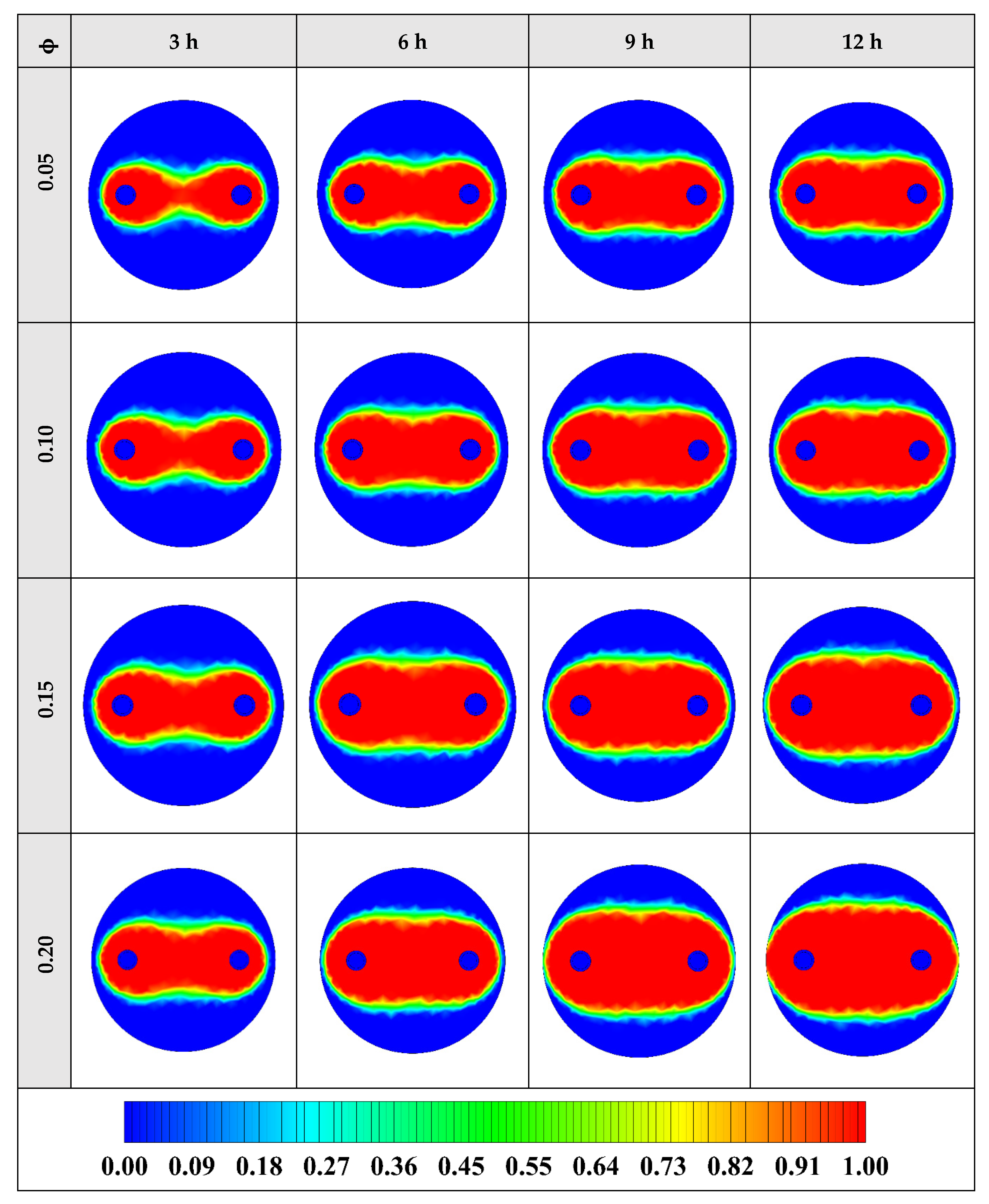
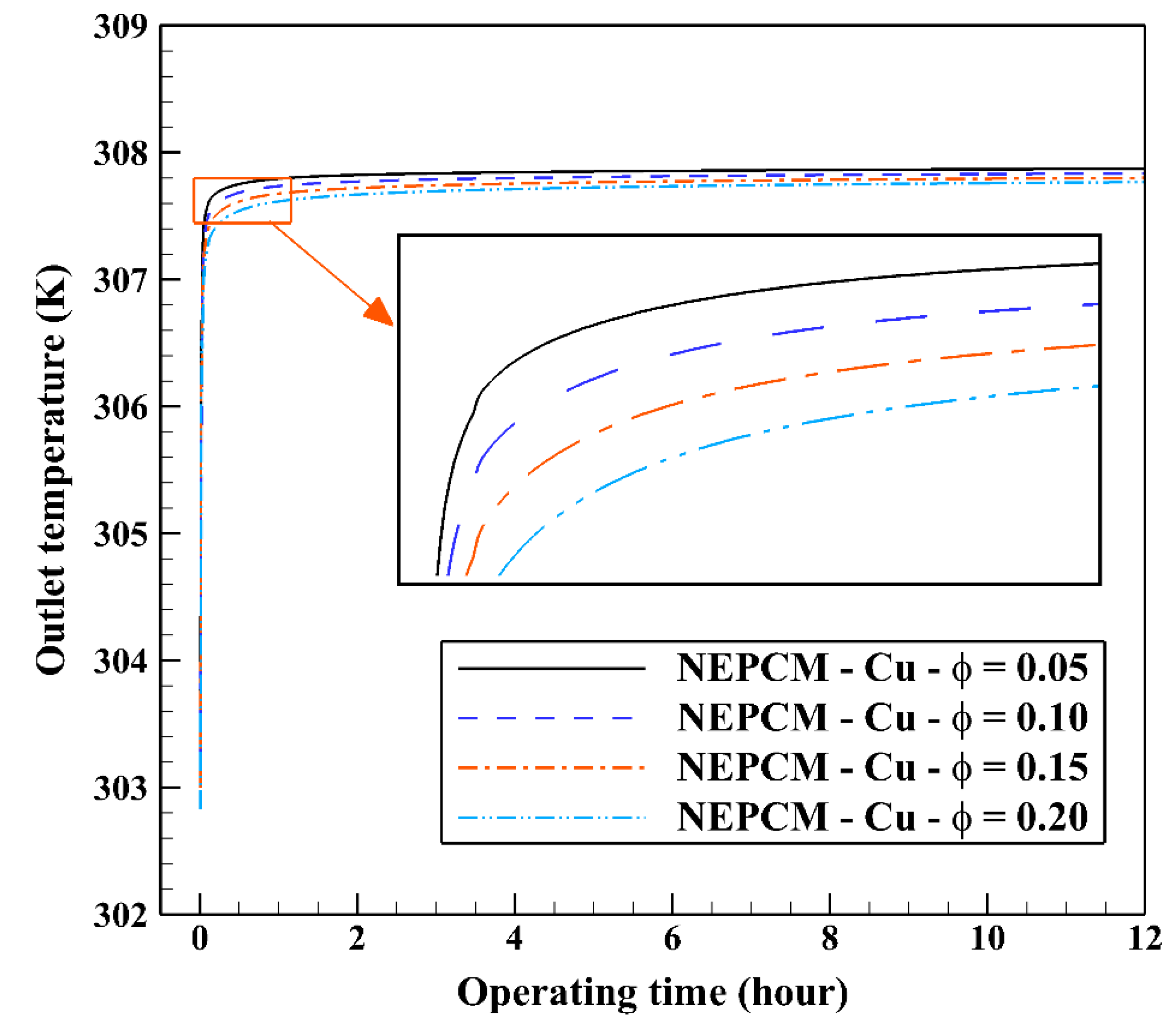
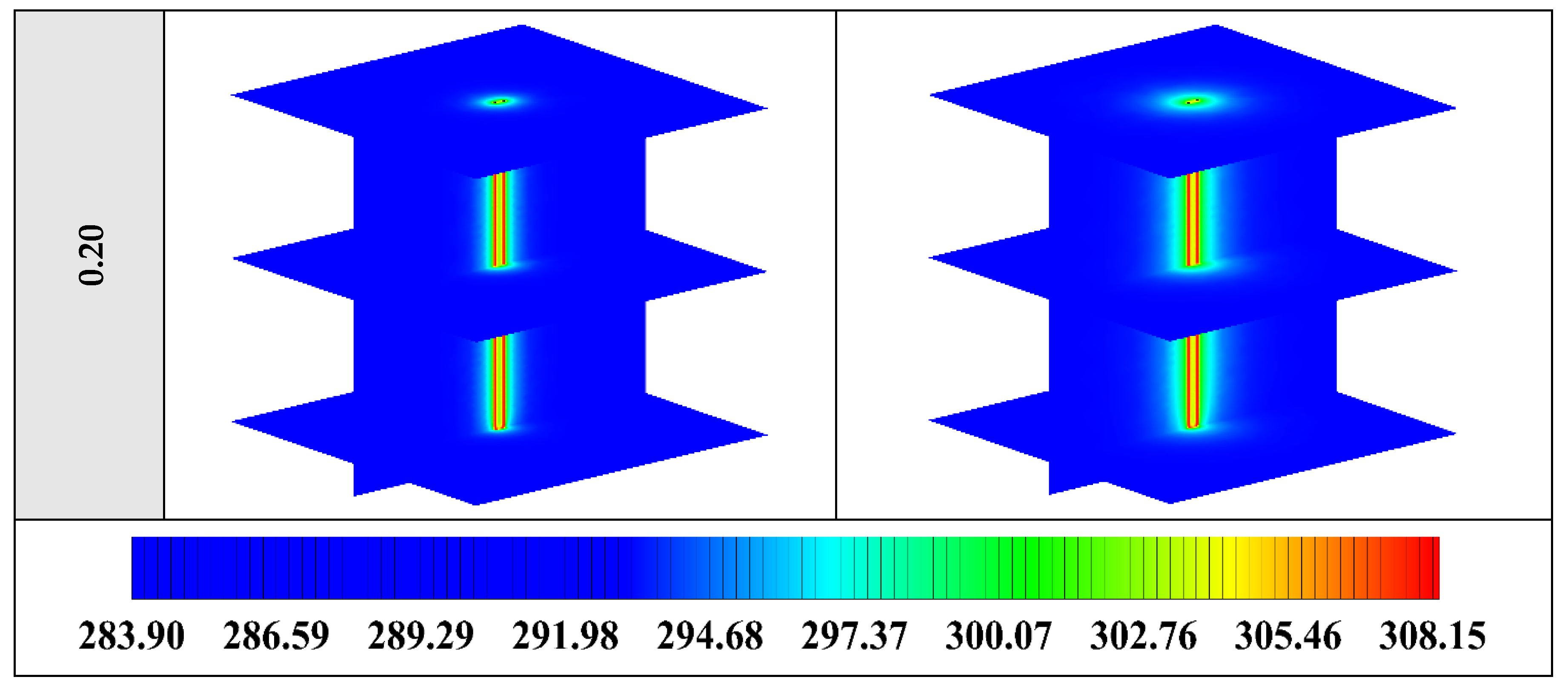
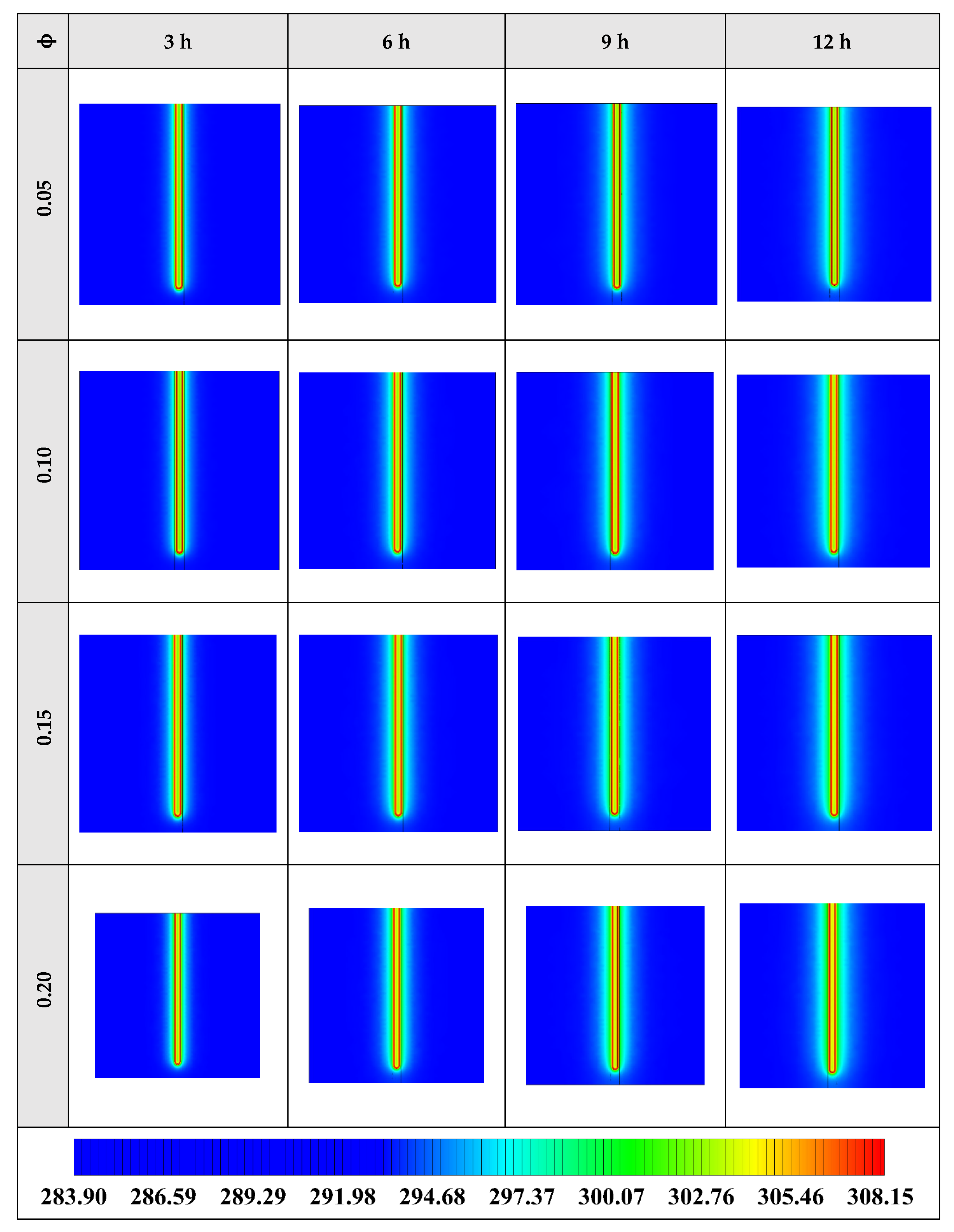
5.2. Impact of Nano-Enhanced Phase Change Material Volume Fraction (ϕ)

In the second step of the study, the volume fraction of Cu nanoparticles was varied from 0.05 to 0.2 while the shape factor is fixed at 3. The range of volume fraction of nanoparticles (0–20%) is chosen based on the past NEPCM published articles, e.g., [33,34,35,36,37,38,39,40,41]. Twenty percent is the maximum percentage of nanoparticles’ volume fraction that has been dispersed into the base fluid to prepare a NEPCM thus far [39,40,41]. The variation of the liquid fraction with operating time at various volume fractions of the NEPCM containing Cu nanoparticles is represented in Figure 9. Based on this figure, the increase in the volume fraction of Cu nanoparticles improves markedly the melting rate of NEPCM, being 0.2 the most favorable volume fraction. The maximum and the minimum values of liquid fraction, 0.57 and 0.36, are obtained by 0.2 and 0.05 of Cu nanoparticles’ volume fractions, respectively. The thermal conductivity of the NEPCM, which is calculated by Equation (5), can increase up to 55% when using Cu nanoparticles at 20% of volume fraction compared to the pure PCM. The differences between the curves are noticeable, highlighting the great influence of nanoparticles’ volume fraction on the cooling operation of the studied BHE.
The contours of liquid fraction for various volume fractions at four different operating times including 3, 6, 9, and 12 h are illustrated in Figure 10. It should be noted that as the volume concentration of the nanoparticle in the NEPCM increases, the thermal conductivity of the NEPCM rises which leads to higher heat transferring and melting rate. This fact is shown clearly in Figure 10. Accordingly, at higher volume concentrations of the Cu nanoparticles in the NEPCM, the melted PCM (red region) is more than the lower volume fractions.
Also, Figure 11 shows the variation of the outlet temperature with operating time at various volume fractions of the NEPCM containing Cu nanoparticles. It is observed that the inlet temperature can be reduced by 0.39 K when adding 20% of the volume fraction of Cu nanoparticles to the PCM. Considering Figure 9 and Figure 11, we select the Cu nanoparticles with the volume fraction of 0.2 as an additive to the PCM for the next part of the evaluation. 2D contours of the temperature distribution of the BHE at various hours of operating using different NEPCMs when n = 3 and Z = 0 are illustrated in Figure 12.
Figure 12 shows that by using NEPCM with a higher volume concentration of nanoparticle, the heat transfer rate between the fluid in the U-tube and the PCM and consequently between PCM and soil can be considerable. Because as noted previously, a higher volume concentration of the nanoparticle leads to increasing the thermal conductivity of the NEPCM. Therefore, it causes more heat exchanging and better melting of the NEPCM. To realize better the melting process and heat transfer of the BHE, 3D contours of temperature distribution and 2D contours of temperature distribution (front view, middle plane) of the BHE are presented in Figure A2. (Appendix A) and Figure A5. (Appendix B), respectively.

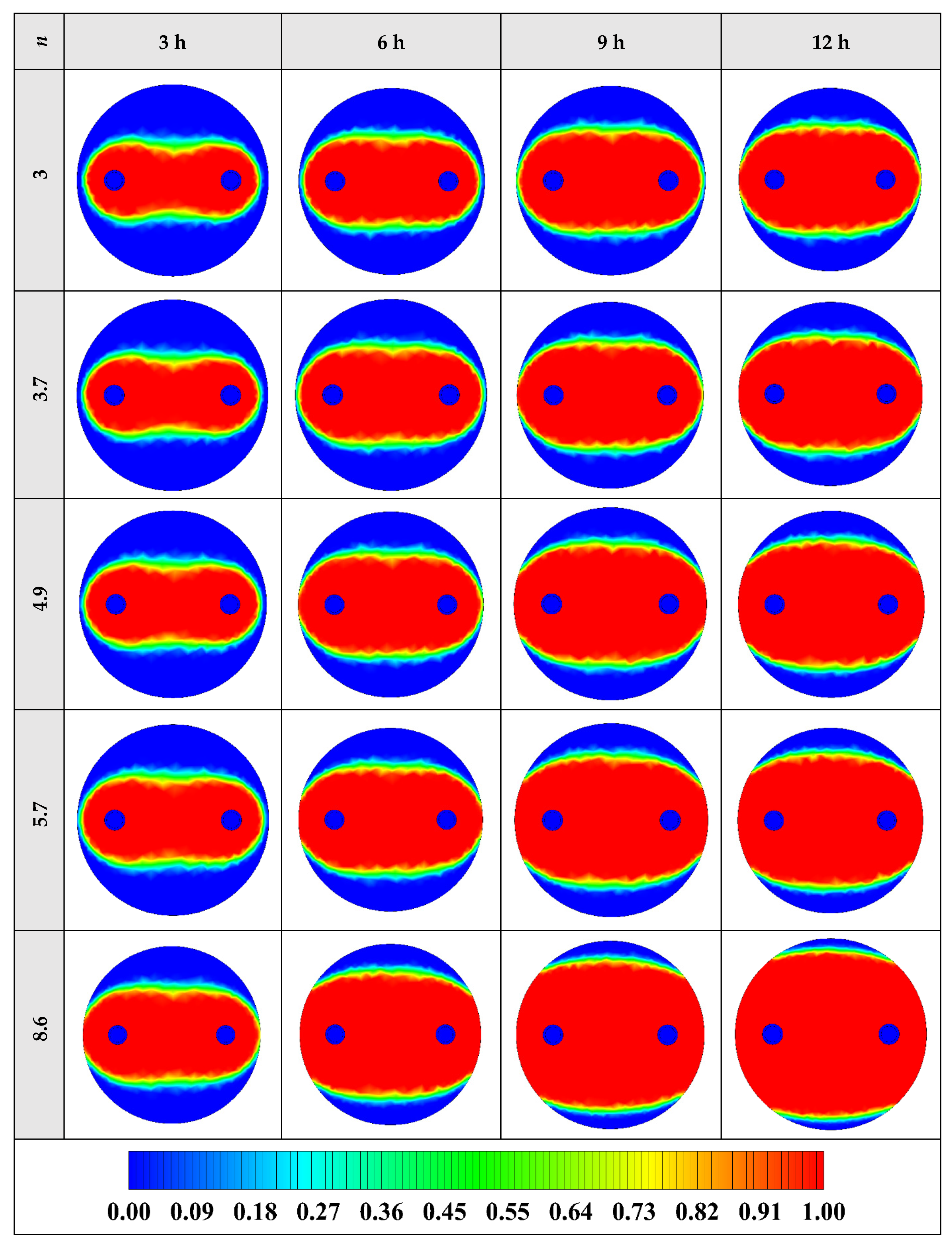
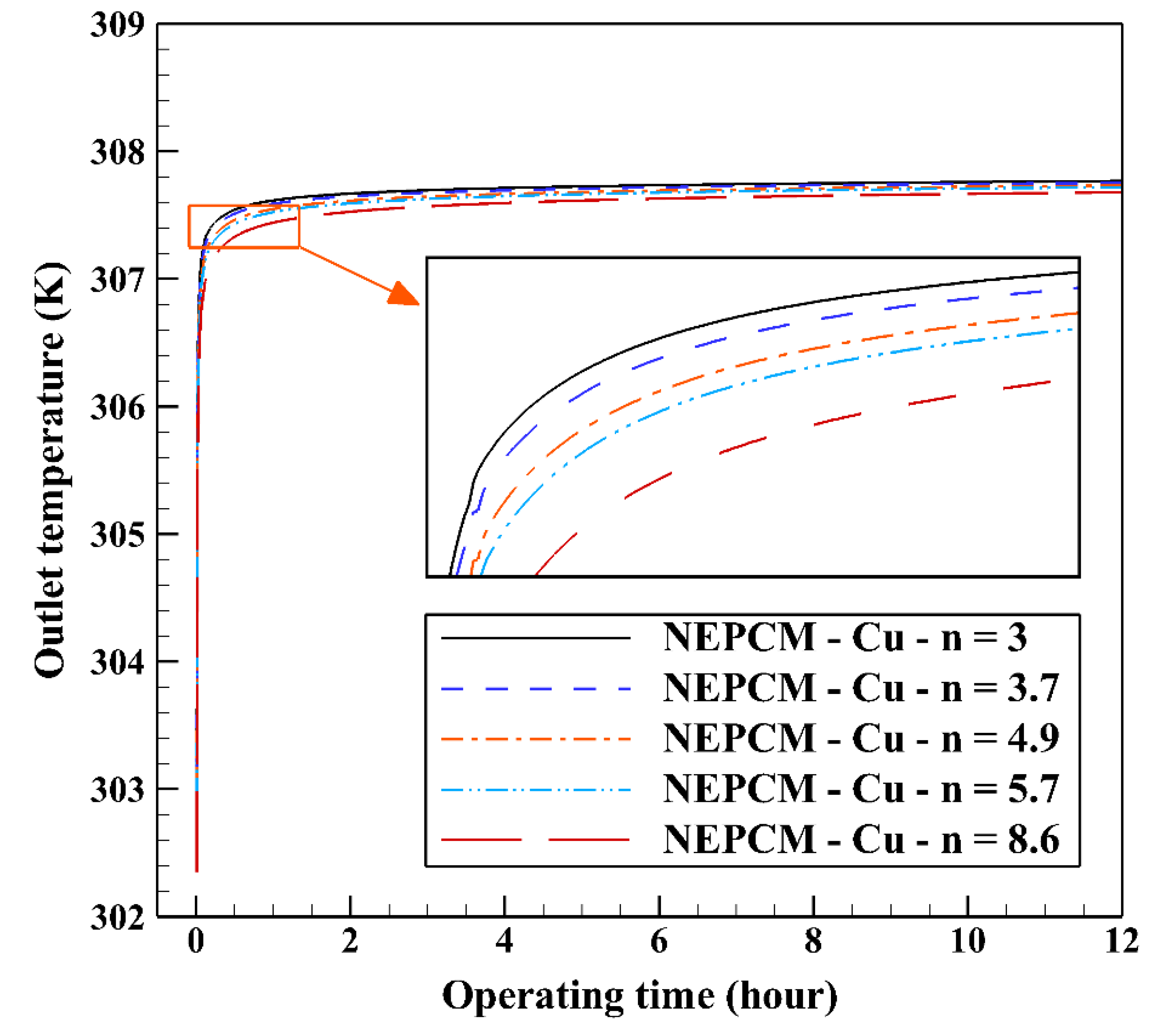
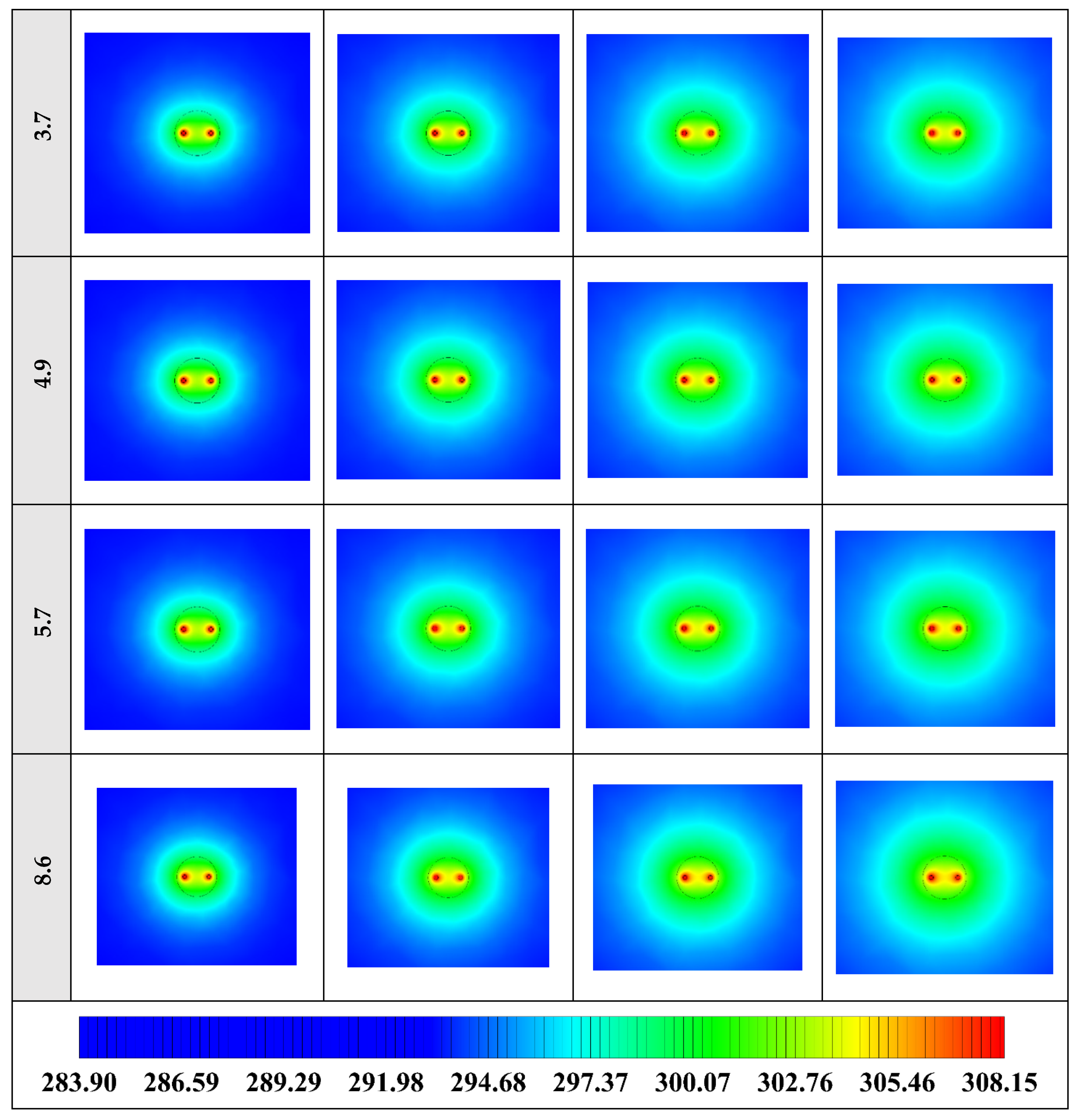
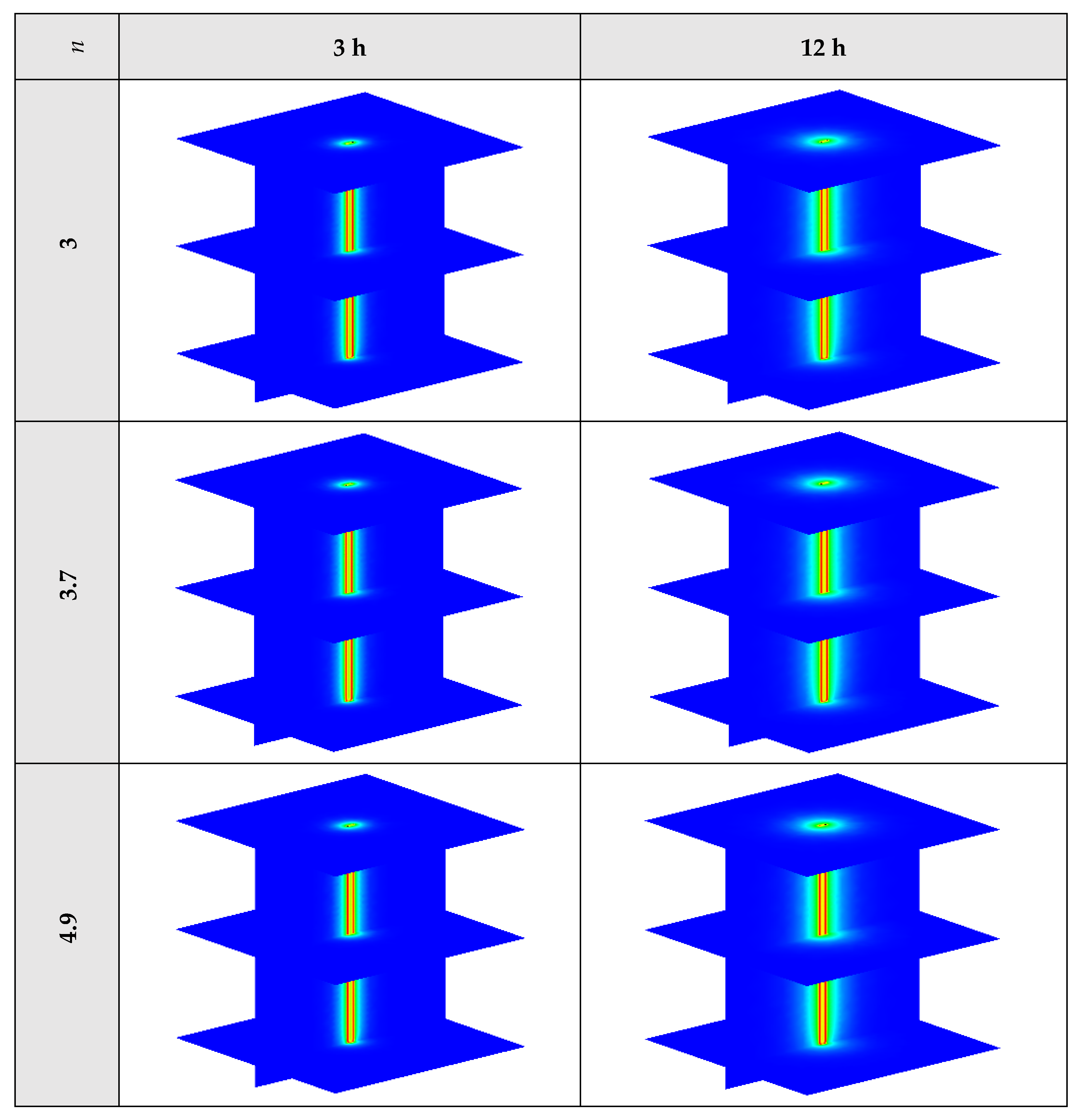
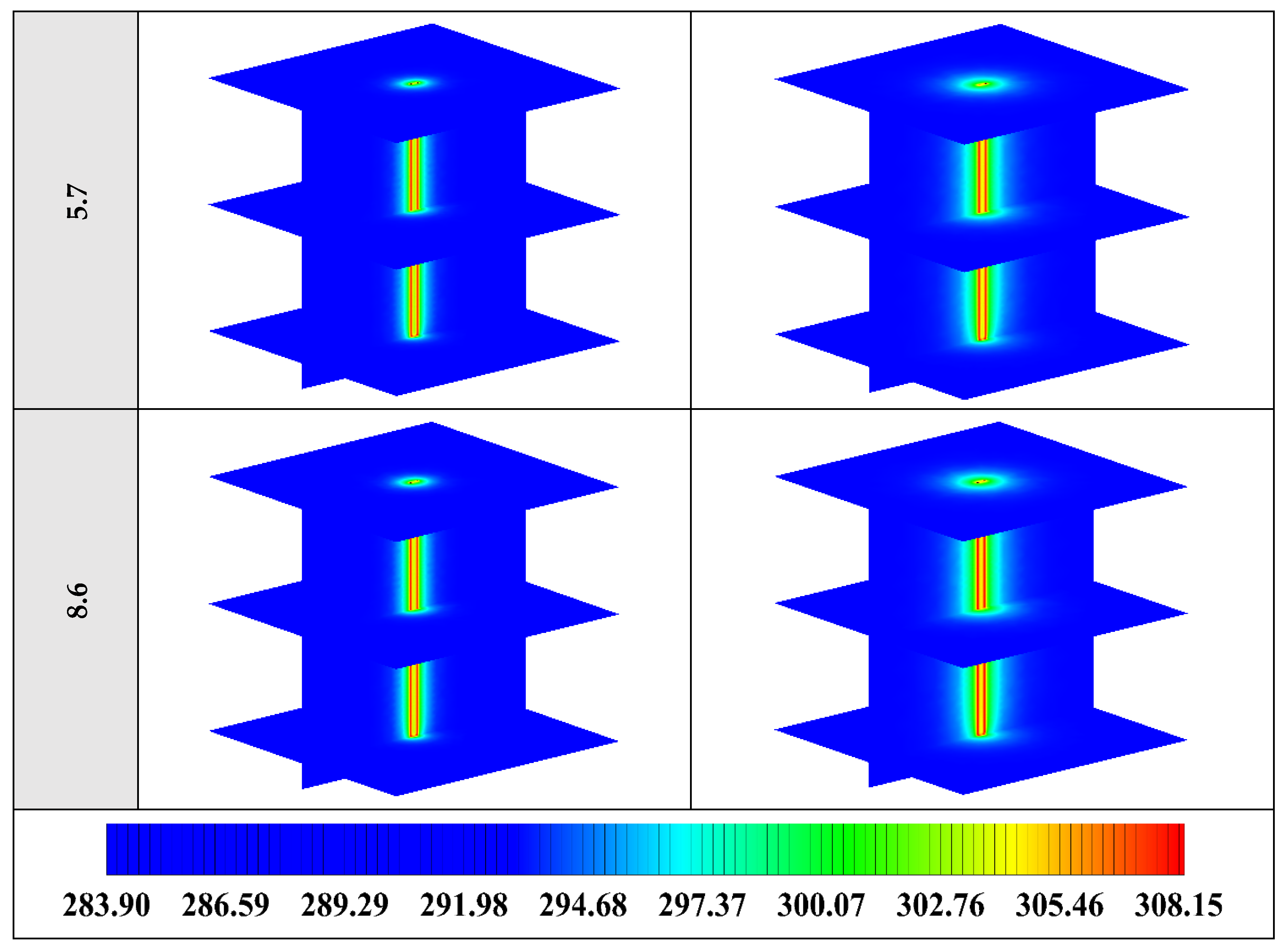
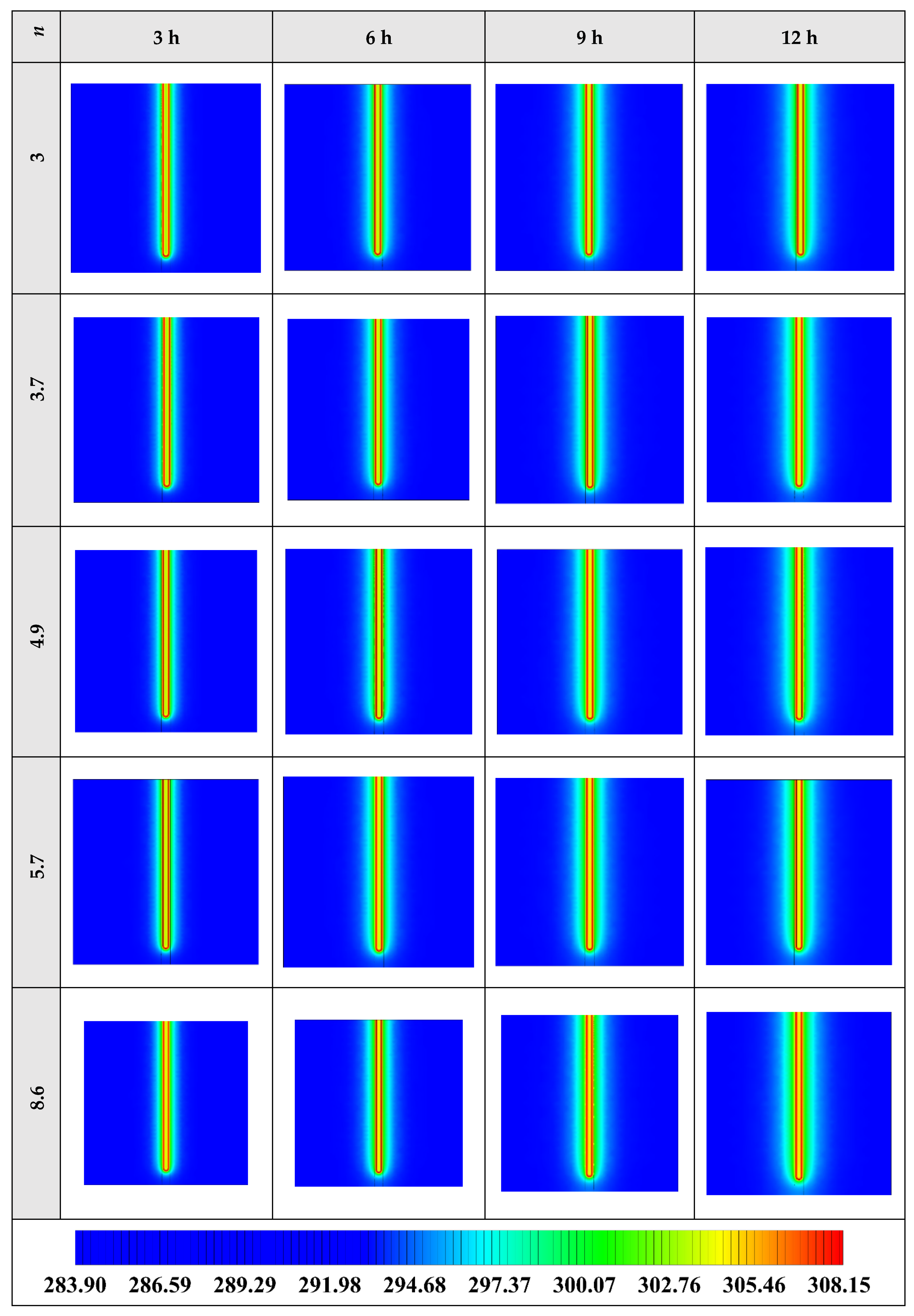
5.3. Impact of Nano-Enhanced Phase Change Material Shape Factor (n)

The variation of the liquid fraction with operating time at various shape factors of Cu nanoparticles is presented in Figure 13. The considered shape factors are 3, 3.7, 4.9, 5.7, and 8.6, as provided in Table 5, which have impacts on the thermal conductivity of the NEPCM (see Equation (5)). According to Figure 13, n = 8.6 is by far the most appropriate shape factor of the Cu nanoparticles which results in the melting of about 85% of the NEPCM. This means that the blade shape of Cu nanoparticles should be dispersed to the pure Paraffin to enhance remarkably the heat storage capacity of the NEPCM. By changing the shape factor from 8.6 to 3, the liquid fraction of the NEPCM decreases almost 27%. The contours of liquid fraction for various volume fractions at four different operating times such as 3, 6, 9, and 12 h are depicted in Figure 14.
Figure 14 illustrates that as the nanoparticle shape factor rises, the heat transfer and melting rate increase which proves the results presented in Figure 13. Figure 15 demonstrates the variation of the outlet temperature with operating time at various shape factors of Cu nanoparticles. The NEPCM containing the blade shape of Cu nanoparticles (n = 8.6) has better potential to absorb thermal energy from the working fluid and subsequently could reduce noticeably the outlet water temperature (almost 0.48 K) in comparison with the other shapes of Cu nanoparticles dispersed into the pure PCM.
2D contours of the temperature distribution of the BHE at various hours of operating using NEPCM containing Cu nanoparticles with different shape factors when ϕ = 0.20 are illustrated in Figure 16. It is shown that by using NEPCMs with a higher value of nanoparticle shape factor, the heat transfer rate between the fluid in the U-tube and the NEPCM and consequently between the NEPCM and surrounding ground can be improved markedly. For a better understanding of the melting process and heat exchange of BHE components, 3D contours of temperature distribution and 2D contours of temperature distribution (front view, middle plane) of the BHE are presented in Figure A3. (Appendix A) and Figure A6. (Appendix B), respectively.

6. Conclusions and Future Scope

In this study, a 3D numerical model of a single U-tube borehole heat exchanger is investigated by means of commercial computational fluid dynamics code, ANSYS Fluent 18.2, to simulate ground source heat pump cooling operation. The objectives of the research are first to analyze the application of seven kinds of nano-enhanced phase change material made from the addition of Cu, CuO, Al2O3, TiO2, SiO2, multi-wall carbon nanotube, and graphene nanoparticles to the Paraffin as backfill in the borehole heat exchanger; then, to study the effects of volume fraction of nanoparticles which varies from 0.05 to 0.20 on the thermal performance of the borehole heat exchanger; and finally, to evaluate the role of nanoparticles’ shape such as the sphere, brick, cylinder, platelet, and the blade on the melting rate of nano-enhanced phase change material. The obtained results are as follows:
  • The nano-enhanced phase change materials with Cu and SiO2 nanoparticles demonstrated to be the best and worst nanoparticles in improving the thermal performance of the single U-tube borehole heat exchanger, respectively. Therefore, Cu nano-enhanced phase change material was selected for further investigation.
  • In terms of volume fraction, it was founded that the increase in the volume fraction of Cu nanoparticles enhanced considerably the melting rate of nano-enhanced phase change material, being 0.20 the most suitable volume fraction which increased up to 55% the thermal conductivity of the nano-enhanced phase change material in comparison with the pure phase change material.
  • Concerning the shape of nanoparticles, the blade shape was by far the best shape of the Cu nanoparticles which resulted in about 85% melting of the nano-enhanced phase change material.
To sum up, the nano-enhanced phase change material with Cu nanoparticles in the blade shape at 20% of volume fraction showed to have notable potential to absorb thermal energy from the heat transfer fluid and decrease the outlet water temperature compared to the other nanoparticles which were used as the addition to the Paraffin.
It is worth mentioning that this is the first time that a nano-enhanced phase change material is implemented in a borehole heat exchanger; therefore, more numerical studies are necessary to extend the flow solver to model the melting and solidification processes in the proposed borehole heat exchanger. Also, performing experimental tests for both the charging/discharging process are required to see how the borehole heat exchanger equipped with nano-enhanced phase change material works in a real project.

Author Contributions

Investigation, Software, Validation, Writing—original draft, H.J.; Funding acquisition, Supervision, Writing—review & editing, J.F.U.; Formal analysis, Methodology, Validation, Writing—review & editing, S.S.M.A.; Writing—review & editing, B.B. All authors have read and agreed to the published version of the manuscript.

Funding

This research work has been supported financially by the European project GEOCOND (funded by the European Union’s Horizon 2020 research and innovation program under grant agreement No 727583) and by the European project GEO4CIVHIC (funded by the European Union’s Horizon 2020 research and innovation program under grant agreement No 792355).

Conflicts of Interest

The authors declare no conflict of interest.

Nomenclature

CpSpecific heat (J·kg−1·K−1)
CmushMushy zone constant
g Gravitational acceleration (m·s−2)
hEnthalpy (J·kg−1)
kThermal conductivity (W·m−1·K−1)
nShape factor
LLatent heat of nano-enhanced phase change material (J·kg−1)
PPressure (Pa)
rRadius (m)
S Source term of momentum equation
tTime (Second)
TTemperature (K)
V Velocity vector (m·s−1)
Greek Symbols
βThermal expansion coefficient (K−1)
λLiquid fraction
μDynamic viscosity (Pa·s)
ρDensity (kg·m−3)
ϕVolume fraction of nanoparticle
Subscripts
0Original
refReference
totTotal
latLatent heat
sensSensible heat
mMelting
Abbreviation
GSHPGround source heat pump
GHEGround heat exchanger
BHEBorehole heat exchanger
TESThermal energy storage
CFDComputational fluid dynamics
PCMPhase change material
NEPCMNano-enhanced phase change material
SSPCMShape-stabilized PCM
MWCNTMulti-wall carbon nanotube

Appendix A

3D contours of the temperature distribution of the BHE at various hours of operating for different cases are listed in the present Appendix A.
Figure A1. 3D contours of the temperature distribution of the BHE at various hours of operating for different NEPCMs when ϕ = 0.20, n = 3.
Energies 13 05156 g0a1aEnergies 13 05156 g0a1bEnergies 13 05156 g0a1c
Figure A2. 3D contours of the temperature distribution of the BHE at various hours of operating for NEPCM containing Cu nanoparticles with different volume fractions when n = 3.
Energies 13 05156 g0a2aEnergies 13 05156 g0a2b
Figure A3. 3D contours of the temperature distribution of the BHE at various hours of operating for NEPCM containing Cu nanoparticles with different shape factors when ϕ = 0.20.
Energies 13 05156 g0a3aEnergies 13 05156 g0a3b

Appendix B

2D contours (front view, middle plane) of the temperature distribution of the BHE at various hours of operating for different cases are shown in the present Appendix B.
Figure A4. 2D contours of the temperature distribution of the BHE at various hours of operating for different NEPCMs when ϕ = 0.20, n = 3 (Front view, middle plane).
Energies 13 05156 g0a4aEnergies 13 05156 g0a4bEnergies 13 05156 g0a4c
Figure A5. 2D contours of the temperature distribution of the BHE at various hours of operating for NEPCM containing Cu nanoparticles with different volume fractions when n = 3 (Front view, middle plane).
Energies 13 05156 g0a5
Figure A6. 2D contours of the temperature distribution of the BHE at various hours of operating for NEPCM containing Cu nanoparticles with different shape factors when ϕ = 0.20 (Front view, middle plane).
Energies 13 05156 g0a6

References

  1. Javadi, H.; Ajarostaghi, S.S.M.; Rosen, M.A.; Pourfallah, M. Performance of ground heat exchangers: A comprehensive review of recent advances. Energy 2019, 178, 207–233. [Google Scholar] [CrossRef]
  2. Javadi, H.; Ajarostaghi, S.S.M.; Pourfallah, M.; Zaboli, M. Performance analysis of helical ground heat exchangers with different configurations. Appl. Therm. Eng. 2019, 154, 24–36. [Google Scholar] [CrossRef]
  3. Javadi, H.; Ajarostaghi, S.S.M.; Ajarostaghi, S.S.M.; Pourfallah, M. Thermal analysis of a triple helix ground heat exchanger using numerical simulation and multiple linear regression. Geothermics 2019, 81, 53–73. [Google Scholar] [CrossRef]
  4. Javadi, H.; Ajarostaghi, S.S.M.; Rosen, M.A.; Pourfallah, M. A Comprehensive Review of Backfill Materials and Their Effects on Ground Heat Exchanger Performance. Sustainability 2018, 10, 4486. [Google Scholar] [CrossRef] [Green Version]
  5. Quaggiotto, D.; Zarrella, A.; Emmi, G.; De Carli, M.; Pockelé, L.; Vercruysse, J.; Psyk, M.; Righini, D.; Galgaro, A.; Mendrinos, D.; et al. Simulation-Based Comparison Between the Thermal Behavior of Coaxial and Double U-Tube Borehole Heat Exchangers. Energies 2019, 12, 2321. [Google Scholar] [CrossRef] [Green Version]
  6. Serageldin, A.A.; Radwan, A.; Sakata, Y.; Katsura, T.; Nagano, K. The Effect of Groundwater Flow on the Thermal Performance of a Novel Borehole Heat Exchanger for Ground Source Heat Pump Systems: Small Scale Experiments and Numerical Simulation. Energies 2020, 13, 1418. [Google Scholar] [CrossRef] [Green Version]
  7. Sapińska-Śliwa, A.; Sliwa, T.; Twardowski, K.; Szymski, K.; Gonet, A.; Żuk, P. Method of Averaging the Effective Thermal Conductivity Based on Thermal Response Tests of Borehole Heat Exchangers. Energies 2020, 13, 3737. [Google Scholar] [CrossRef]
  8. Janiszewski, M.; Hernández, E.C.; Siren, T.; Uotinen, L.; Kukkonen, I.T.; Rinne, M. In Situ Experiment and Numerical Model Validation of a Borehole Heat Exchanger in Shallow Hard Crystalline Rock. Energies 2018, 11, 963. [Google Scholar] [CrossRef] [Green Version]
  9. Patil, M.S.; Seo, J.-H.; Kang, S.-J.; Lee, M.-Y. Review on Synthesis, Thermo-Physical Property, and Heat Transfer Mechanism of Nanofluids. Energies 2016, 9, 840. [Google Scholar] [CrossRef] [Green Version]
  10. Cao, S.-J.; Kong, X.-R.; Deng, Y.; Zhang, W.; Yang, L.; Ye, Z.-P. Investigation on thermal performance of steel heat exchanger for ground source heat pump systems using full-scale experiments and numerical simulations. Appl. Therm. Eng. 2017, 115, 91–98. [Google Scholar] [CrossRef]
  11. Li, B.; Zheng, M.; Shahrestani, M.; Zhang, S. Driving factors of the thermal efficiency of ground source heat pump systems with vertical boreholes in Chongqing by experiments. J. Build. Eng. 2020, 28, 101049. [Google Scholar] [CrossRef]
  12. Wang, J.L.; De Zhao, J.; Liu, N. Numerical Simulation of Borehole Heat Transfer with Phase Change Material as Grout. Appl. Mech. Mater. 2014, 577, 44–47. [Google Scholar] [CrossRef]
  13. Lei, H.Y.; Dai, C.S. Heat transfer analysis of centric borehole heat exchanger with different backfill materials. In Proceedings of the World Geothermal Congress, Melbourne, Australia, 19–25 April 2015. [Google Scholar]
  14. Li, X.; Tong, C.; Duanmu, L.; Liu, L. Research on U-tube Heat Exchanger with Shape-stabilized Phase Change Backfill Material. Procedia Eng. 2016, 146, 640–647. [Google Scholar] [CrossRef] [Green Version]
  15. Li, X.; Tong, C.; Duanmu, L.; Liu, L. Study of a U-tube heat exchanger using a shape-stabilized phase change backfill material. Sci. Technol. Built Environ. 2017, 23, 1–11. [Google Scholar] [CrossRef]
  16. Qi, D.; Pu, L.; Sun, F.; Li, Y. Numerical investigation on thermal performance of ground heat exchangers using phase change materials as grout for ground source heat pump system. Appl. Therm. Eng. 2016, 106, 1023–1032. [Google Scholar] [CrossRef]
  17. Chen, F.; Mao, J.; Chen, S.; Li, C.; Hou, P.; Liao, L. Efficiency analysis of utilizing phase change materials as grout for a vertical U-tube heat exchanger coupled ground source heat pump system. Appl. Therm. Eng. 2018, 130, 698–709. [Google Scholar] [CrossRef]
  18. Chen, F.; Mao, J.; Li, C.; Hou, P.; Li, Y.; Xing, Z.; Chen, S. Restoration performance and operation characteristics of a vertical U-tube ground source heat pump system with phase change grouts under different running modes. Appl. Therm. Eng. 2018, 141, 467–482. [Google Scholar] [CrossRef]
  19. Zhang, M.; Liu, X.; Biswas, K.; Warner, J. A three-dimensional numerical investigation of a novel shallow bore ground heat exchanger integrated with phase change material. Appl. Therm. Eng. 2019, 162, 114297. [Google Scholar] [CrossRef]
  20. Yang, W.; Xu, R.; Yang, B.; Yang, J. Experimental and numerical investigations on the thermal performance of a borehole ground heat exchanger with PCM backfill. Energy 2019, 174, 216–235. [Google Scholar] [CrossRef]
  21. Bottarelli, M.; Georgiev, A.; Aydin, A.A.; Su, Y.; Yousif, C. Ground-source heat pumps using phase change materials. In Proceedings of the European Geothermal Congress, Pisa, Italy, 3–7 June 2013. [Google Scholar]
  22. Michele, B.; Bortoloni, M.; Su, Y.; Yousif, C.; Aydın, A.A.; Georgiev, A. Numerical analysis of a novel ground heat exchanger coupled with phase change materials. Appl. Therm. Eng. 2015, 88, 369–375. [Google Scholar] [CrossRef]
  23. Michele, B.; Bortoloni, M.; Su, Y. Heat transfer analysis of underground thermal energy storage in shallow trenches filled with encapsulated phase change materials. Appl. Therm. Eng. 2015, 90, 1044–1051. [Google Scholar] [CrossRef]
  24. Rabin, Y.; Korin, E. Incorporation of phase-change materials into a ground thermal energy storage system: Theoretical study. J. Energy Resour. Technol. 1996, 118, 237–241. [Google Scholar] [CrossRef]
  25. Hüseyin, B.; Durmuş, A. Evaluation of ground-source heat pump combined latent heat storage system performance in greenhouse heating. Energy Build. 2009, 41, 220–228. [Google Scholar] [CrossRef]
  26. Hüseyin, B. Energetic performance analysis of a ground-source heat pump system with latent heat storage for a greenhouse heating. Energy Convers. Manag. 2011, 52, 581–589. [Google Scholar] [CrossRef]
  27. Dehdezi, P.K.; Hall, M.R.; Dawson, A.R. Enhancement of soil thermo-physical properties using microencapsulated phase change materials for ground source heat pump applications. Appl. Mech. Mater. 2011, 110, 1191–1198. [Google Scholar] [CrossRef]
  28. Eslami-nejad, P.; Bernier, M. A preliminary assessment on the use of phase change materials around geothermal boreholes. ASHRAE Trans. 2013, 119, 312–321. [Google Scholar]
  29. Na, Z.; Hu, P.; Lei, Y.; Jiang, Z.; Lei, F. Numerical study on ground source heat pump integrated with phase change material cooling storage system in office building. Appl. Therm. Eng. 2015, 87, 615–623. [Google Scholar]
  30. Jun-Seo, J.; Lee, S.R.; Kim, M.J. Benefit of phase change material on the performance of horizontal ground heat exchanger: A numerical study. In Proceedings of the World Congress on Advances in Civil, Environmental, and Materials Research, Jeju Island, Korea, 28 August–1 September 2016. [Google Scholar]
  31. Alkhwildi, A.; Elhashmi, R.; Chiasson, A. Parametric modeling and simulation of Low temperature energy storage for cold-climate multi-family residences using a geothermal heat pump system with integrated phase change material storage tank. Geothermics 2020, 86, 101864. [Google Scholar] [CrossRef]
  32. Pu, L.; Xu, L.; Zhang, S.; Li, Y. Optimization of ground heat exchanger using microencapsulated phase change material slurry based on tree-shaped structure. Appl. Energy 2019, 240, 860–869. [Google Scholar] [CrossRef]
  33. Khodadadi, J.M.; Hosseinizadeh, S.F. Nanoparticle-enhanced phase change materials (NEPCM) with great potential for improved thermal energy storage. Int. Commun. Heat Mass Transf. 2007, 34, 534–543. [Google Scholar] [CrossRef]
  34. Kalaiselvam, S.; Parameshwaran, R.; Harikrishnan, S. Analytical and experimental investigations of nanoparticles embedded phase change materials for cooling application in modern buildings. Renew. Energy 2012, 39, 375–387. [Google Scholar] [CrossRef]
  35. Pahamli, Y.; Hosseini, M.J.; Ranjbar, A.; Bahrampoury, R. Effect of nanoparticle dispersion and inclination angle on melting of PCM in a shell and tube heat exchanger. J. Taiwan Inst. Chem. Eng. 2017, 81, 316–334. [Google Scholar] [CrossRef]
  36. Ramakrishnan, S.; Wang, X.; Sanjayan, J.; Wilson, J. Heat transfer performance enhancement of paraffin/expanded perlite phase change composites with graphene nano-platelets. Energy Procedia 2017, 105, 4866–4871. [Google Scholar] [CrossRef]
  37. Rufuss, D.; Winfred, D.; Suganthi, L.; Iniyan, S.; Davies, P.A. Effects of nanoparticle-enhanced phase change material (NPCM) on solar still productivity. J. Clean. Prod. 2018, 192, 9–29. [Google Scholar] [CrossRef] [Green Version]
  38. Farzanehnia, A.; Khatibi, M.; Sardarabadi, M.; Passandideh-Fard, M. Experimental investigation of multiwall carbon nanotube/paraffin based heat sink for electronic device thermal management. Energy Convers. Manag. 2019, 179, 314–325. [Google Scholar] [CrossRef]
  39. Yang, L.; Huang, J.-N.; Zhou, F. Thermophysical properties and applications of nano-enhanced PCMs: An update review. Energy Convers. Manag. 2020, 214, 112876. [Google Scholar] [CrossRef]
  40. Tariq, S.L.; Ali, H.M.; Akram, M.A.; Janjua, M.M.; Ahmadlouydarab, M. Nanoparticles enhanced phase change materials (NePCMs)-A recent review. Appl. Therm. Eng. 2020, 176, 115305. [Google Scholar] [CrossRef]
  41. Leong, K.Y.; Rahman, M.R.A.; Gurunathan, B. Nano-enhanced phase change materials: A review of thermo-physical properties, applications and challenges. J. Energy Storage 2019, 21, 18–31. [Google Scholar] [CrossRef]
  42. Dhaidan, N.S.; Khodadadi, J.; Al-Hattab, T.; Al-Mashat, S.M. Experimental and numerical investigation of melting of NePCM inside an annular container under a constant heat flux including the effect of eccentricity. Int. J. Heat Mass Transf. 2013, 67, 455–468. [Google Scholar] [CrossRef]
  43. Khodadadi, J.M.; Fan, L. Expedited freezing of nanoparticle-enhanced phase change materials (NEPCM) exhibited through a simple 1-D stefan problem formulation. In Proceedings of the Heat Transfer Summer Conference, San Francisco, CA, USA, 19–23 July 2009. [Google Scholar]
  44. Babapoor, A.; Karimi, G. Thermal properties measurement and heat storage analysis of paraffinnanoparticles composites phase change material: Comparison and optimization. Appl. Therm. Eng. 2015, 90, 945–951. [Google Scholar] [CrossRef]
  45. Shadab, S.; Lafdi, K.; Hallinan, K. Carbon nanoadditives to enhance latent energy storage of phase change materials. J. Appl. Phys. 2008, 103, 94302. [Google Scholar] [CrossRef] [Green Version]
  46. Karunesh, K.; Shukla, A.; Sharma, A.; Biwole, P.H. Heat transfer study of phase change materials with graphene nano particle for thermal energy storage. Sol. Energy 2017, 146, 453–463. [Google Scholar] [CrossRef]
  47. Hamilton, R.L.; Crosser, O.K. Thermal conductivity of heterogeneous two-component systems. Ind. Eng. Chem. Fundam. 1962, 1, 187–191. [Google Scholar] [CrossRef]
  48. Timofeeva, E.V.; Routbort, J.L.; Singh, D. Particle shape effects on thermophysical properties of alumina nanofluids. J. Appl. Phys. 2009, 106, 014304. [Google Scholar] [CrossRef]
  49. Shi, X.; Jaryani, P.; Amiri, A.; Rahimi, A.; Malekshah, E.H. Heat transfer and nanofluid flow of free convection in a quarter cylinder channel considering nanoparticle shape effect. Powder Technol. 2019, 346, 160–170. [Google Scholar] [CrossRef]
  50. Ajarostaghi, M.; Soheil, S.; Poncet, S.; Sedighi, K.; Delavar, M.A. Numerical modeling of the melting process in a shell and coil tube ice storage system for air-conditioning application. Appl. Sci. 2019, 9, 2726. [Google Scholar] [CrossRef] [Green Version]
  51. Afsharpanah, F.; Ajarostaghi, S.S.M.; Sedighi, K. The influence of geometrical parameters on the ice formation enhancement in a shell and double coil ice storage system. SN Appl. Sci. 2019, 1, 1264. [Google Scholar] [CrossRef] [Green Version]
  52. Khashayar, P.; Ajarostaghi, S.S.M.; Sedighi, K. Numerical simulation of solidification process in an ice-on-coil ice storage system with serpentine tubes. SN Appl. Sci. 2019, 1, 1258. [Google Scholar] [CrossRef] [Green Version]
  53. Ajarostaghi, M.; Soheil, S.; Sedighi, K.; Delavar, M.A.; Poncet, S. Numerical study of a horizontal and vertical shell and tube ice storage systems considering three types of tube. Appl. Sci. 2020, 10, 1059. [Google Scholar] [CrossRef] [Green Version]
  54. Ajarostaghi, M.; Soheil, S.; Sedighi, K.; Delavar, M.A.; Poncet, S. Influence of geometrical parameters arrangement on solidification process of ice-on-coil storage system. SN Appl. Sci. 2019, 2, 109. [Google Scholar] [CrossRef] [Green Version]
  55. Ajarostaghi, M.; Soheil, S.; Delavar, M.A.; Dolati, A. Numerical investigation of melting process in phase change material (PCM) cylindrical storage considering different geometries. Heat Transf. Res. 2017, 48, 1515–1529. [Google Scholar] [CrossRef]
Figure 1. Schematic of the studied BHE: (a) 3D view, and (b) 2D view (Ground surface).
Energies 13 05156 g001aEnergies 13 05156 g001b
Figure 2. The meshing of the studied BHE: (a) 3D view, and (b) 2D view (Ground surface).
Energies 13 05156 g002
Figure 3. Three different radiuses selected for validation.
Energies 13 05156 g003
Figure 4. Validation of the numerical backfill and soil temperatures at different radiuses to the experimental results of Yang et al. [20].
Energies 13 05156 g004
Figure 5. Variation of the liquid fraction with operating time using different NEPCMs at ϕ = 0.20 and n = 3.
Energies 13 05156 g005
Figure 6. 2D contours of the liquid fraction of different NEPCMs at various hours of operating when ϕ = 0.20 and n = 3 (Top view at Z = 0).
Energies 13 05156 g006aEnergies 13 05156 g006b
Figure 7. Variation of the outlet temperature with operating time when using different NEPCMs at ϕ = 0.20 and n = 3.
Energies 13 05156 g007
Figure 8. 2D contours of the temperature distribution of the BHE at various hours of operating using different NEPCMs when ϕ = 0.20 and n = 3. (Top view at Z = 0).
Energies 13 05156 g008aEnergies 13 05156 g008b
Figure 9. Variation of the liquid fraction with operating time at various volume fractions of the NEPCM containing Cu nanoparticles when n = 3.
Energies 13 05156 g009
Figure 10. 2D contours of the liquid fraction of NEPCM containing Cu nanoparticles with different volume fractions at various hours of operating when n = 3 (Top view at Z = 0).
Energies 13 05156 g010
Figure 11. Variation of the outlet temperature with operating time at various volume fractions of the NEPCM containing Cu nanoparticles when n = 3.
Energies 13 05156 g011
Figure 12. 2D contours of the temperature distribution of the BHE at various hours of operating when using NEPCM containing Cu nanoparticles with different volume fractions at n = 3 (Top view at Z = 0).
Energies 13 05156 g012aEnergies 13 05156 g012b
Figure 13. Variation of the liquid fraction with operating time at various shape factors of Cu nanoparticles when ϕ = 0.20.
Energies 13 05156 g013
Figure 14. 2D contours of the liquid fraction of NEPCM containing Cu nanoparticles with different shape factors at various hours of operating when ϕ = 0.20 (Top view at Z = 0).
Energies 13 05156 g014
Figure 15. Variation of the outlet temperature with operating time at various shape factors of Cu nanoparticles when ϕ = 0.20.
Energies 13 05156 g015
Figure 16. 2D contours of the temperature distribution of the BHE at various hours of operating using NEPCM containing Cu nanoparticles with different shape factors when ϕ = 0.20. (Top view at Z = 0).
Energies 13 05156 g016aEnergies 13 05156 g016b
Table 1. Thermo-physical properties of working fluid, pipe, and ground.
PropertyWorking FluidPipeGround
ρ [kg/m3]998.289781600
Cp [J/kg·K]41823811640
k [W/m·K]0.6387.60.69
μ [Pa·s]0.001003--
Table 2. Thermo-physical properties of different types of NEPCM as backfill.
PropertyPCMNanoparticles
Paraffin (n-Octadecane) [42]Cu [43]CuO [43]Al2O3 [43]TiO2 [43]SiO2 [44]MWCNT [45]Graphene [46]
ρ [kg/m3]7708933651038804175220016002200
Cp [J/kg·K]2196385540792692775796790.1
k [W/m·K]0.1484011842.348.41.3830005000
L [J/kg]243500-------
μ [Pa·s]0.00385-------
Tm [K]301.15-------
Table 3. Grid independence test.
Elements Numbers571,9241,328,8732,244,6713,476,561
Outlet temperature of working fluid (K)307.41307.55307.63307.60
Liquid fraction0.670.690.720.71
Table 4. Geometry details, simulation conditions, and considered variables.
ParametersValue
Calculation domain1.2 × 1.2 × 1.2 m3
U-tube length1.1 m
Borehole depth1.2 m
Borehole diameter0.06 m
Pipe spacing of U-tube (between centers)0.0365 m
Outer diameter of pipe0.0065 m
Inner diameter of pipe0.005 m
Inlet temperature308.15 K
Inlet velocity0.6 m/s
Operating time12 h
NEPCMsAddition of seven nanoparticles including Cu, CuO, Al2O3, TiO2, SiO2, MWCNT, and graphene to the Paraffin
Volume concentration of nanoparticles0.05, 0.10, 0.15, 0.20
Shape of nanoparticlessphere, brick, cylinder, platelet, blade
Table 5. The shape factor for various nanoparticles’ shapes [48,49].
nNanoparticle Shape
3Sphere Energies 13 05156 i001
3.7Brick Energies 13 05156 i002
4.9Cylinder Energies 13 05156 i003
5.7Platelet Energies 13 05156 i004
8.6Blade Energies 13 05156 i005

