1. Introduction
In recent years, several applications have been proposed for resonant inductive Wireless Power Transfer (WPT) [
1,
2,
3,
4]. In fact, resonant inductive WPT is an effective solution for wirelessly energizing electronic devices and several optimal design strategies have been investigated in the literature.
Usually, the goal is to recharge a single device and the focus is on maximizing either the power delivered to the load or the power transfer efficiency. In this regard, the most widely adopted scheme is that using a single transmitter, thus corresponding to a Single-Input Single Output (SISO) configuration. In a SISO configuration the link consists of just two magnetically coupled resonators: a transmitting resonator connected to the source and a receiving resonator connected to the load (i.e., the device to be recharged). SISO configurations have been widely investigated in the literature and it has been demonstrated that the link has to be terminated on its conjugate image impedances for maximizing both the power on the loads and the efficiency [
5,
6,
7].
More recently, schemes using multiple transmitters and/or multiple receivers have been also investigated. The use of Multiple Input Single Output (MISO) schemes could be adopted to obtain an almost constant performance on a given area/volume this being useful if the position of the receiver is affected by small uncertainties (as in the case of embedded devices). In this regard, some interesting results are reported in [
8] where it is demonstrated that a two-dimensional region of nearly constant power transfer efficiency can be obtained by using four transmitters. In [
9] the use of a linear array of transmitters, activated two at time, is suggested for providing a constant output voltage to a load moving along a linear path. The problem of maximizing the efficiency and the power on the load in MISO schemes has been also analyzed and some interesting results have been reported in [
10,
11]. In particular, in [
10] the solution for maximizing the efficiency has been formulated as a convex optimization problem. In [
11] the optimal loads for both the maximum power and the maximum efficiency solutions have been presented for the case of a link using either two–transmitter and a single load or a single transmitter and two–load. In [
12], a more abstract approach was used to maximize the efficiency by modeling the MISO-WPT system as a linear circuit whose input-output relationship is expressed in terms of a small number of unknown parameters that can be thought of as transimpedances and gains.
As per schemes using a Single Transmitter and Multiple Receivers (SIMO), they are adopted to recharge multiple devices with a single transmitter [
13,
14,
15,
16,
17,
18,
19,
20,
21,
22,
23,
24,
25,
26,
27,
28]. In [
20] the use of a multiple-output scheme is suggested for the recharge of electric vehicles. The problem of maximizing the power delivered to the loads has been solved in [
21], where the expressions of the optimal loads have been derived by using the maximum power transfer theorem for an
N–port.
As per the problem of efficiency maximization, in [
23] the use of suitable matching networks is suggested. In [
24], the specific case of a link using two receivers is analyzed and it is demonstrated that for some specific configurations of the receivers it is convenient to use a non-synchronous scheme with receivers resonating at a frequency different from that of the transmitter. In [
22] a SIMO system with constant output voltage and operating at
is presented. The efficiency of the proposed WPT link is optimized by tuning the input voltage at the transmitter side.
In [
25], the loads for maximizing the efficiency have been derived from the expression calculated for the case of a link using one receiver and that using two receivers. However, the analysis is performed assuming that the coupling among the receivers can be neglected, this representing a limitation for real applications. The presence of possible couplings among the receivers has been analyzed in [
26,
27]. It is demonstrated that for given loads a coupling among the receivers can be compensated by using suitable compensating reactances; however, in these papers it is assumed that the loads are given (i.e., they are not optimized).
Finally, for the problem of efficiency maximization, elegant and comprehensive analysis of all possible configurations (i.e., the SIMO, MISO and MIMO configurations) have been presented in [
29,
30]. A very elegant and general approach is presented in [
29]; where, starting from the impedance or scattering matrix of a multiport the efficiency of a generic MIMO-WPT system is expressed by the Rayleigh quotient. However, the method is not applied on an inductive WPT system and the optimal loads are only expressed as function of the port currents and impedance matrix elements. In [
30], the optimal loads are derived from the first-order necessary condition consisting of imposing the zeroing of the first-order partial derivatives of the efficiency with respect to the input and output currents. The optimal solution derived in this way is validated by checking the second order derivatives. The developed analysis is general and overcomes some limitations present in the previous literature. For instance, for the SIMO case a generic number of possibly coupled receivers is considered. Similarly, for the MISO case, the formulas are presented for a generic number of possibly coupled transmitters. However, the analysis developed in [
30] is based on the assumption that all the couplings among the transmitters and the receivers are purely inductive; this assumption limits the applicability of the approach to practical applications where the conductivity of the propagation channel is negligibly small.
In this paper, referring to the SIMO configuration, similarly to [
29], the problem of finding the optimal loads maximizing the efficiency is formulated as a generalized eigenvalue problem. The presented theory is valid for any strictly passive and reciprocal network in SIMO configuration and is applied in detail for the first time in this paper to the case of a resonant inductive WPT link. The application of the presented theory just requires the knowledge of the impedance matrix of the SIMO network that can be the result of measurements, simulations or theoretical derivation. The network must not satisfy any particular hypothesis except that of being passive and reciprocal; consequently, the proposed approach is also applicable in the case of non-purely inductive couplings (including the case of a propagation channel with non-negligible values of the conductivity).
The general theory is first presented for a generic
–port network in SIMO configuration and then applied to the specific case of a resonant inductive WPT link; the analytical expressions of the complex loads maximizing the efficiency are derived and discussed. Additionally, the importance of suitably selecting the generator impedance for maximizing the total output power corresponding to the maximum efficiency solution is discussed. The correctness of the derived expressions is validated by the results reported in [
30] and by numerical data presented in this paper.
The paper is organized as follows. In
Section 2 the problem of efficiency maximization is solved for a generic SIMO
–port network. In
Section 3 the derived equations are specialized for the case of an inductive WPT link, the optimal expressions of the loads and the generator impedances are reported. In
Section 4 theoretical formulas are validated through circuital and full-wave simulations. Finally, some conclusions are drawn in
Section 5.
2. Derivation of the Solution for the General Case
The problem analyzed in this paper is a WPT link using a Single-Input Multiple-Output (SIMO) configuration: a single transmitter is wirelessly connected to N receivers. In this section, the general case is analyzed, no specific assumption is made on the coupling mechanism among the transmitter and the receivers, it is only assumed that the network is passive and reciprocal.
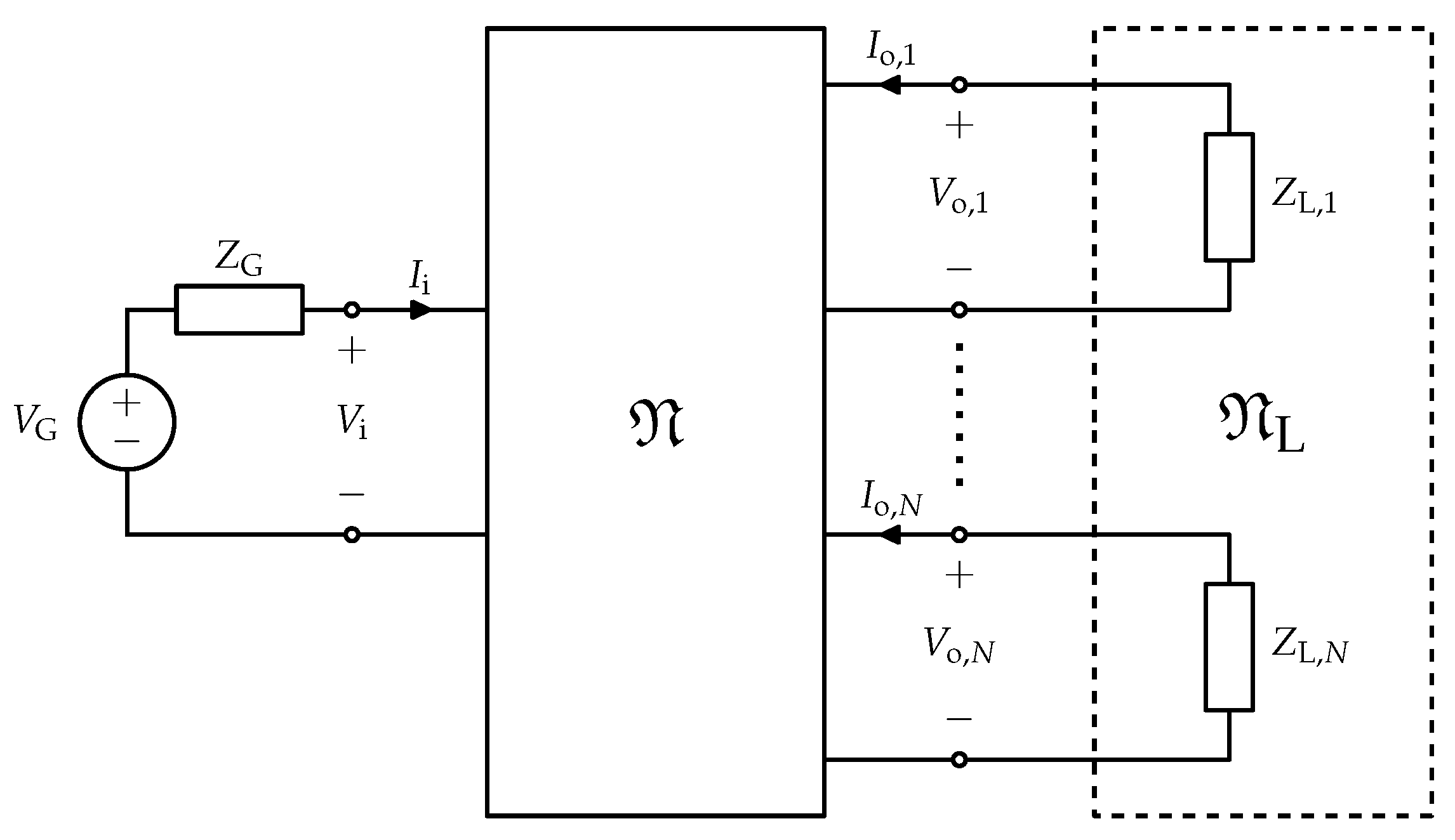
By using a network formalism, the link is modeled as an
–port network
, see
Figure 1, described by its impedance matrix
. The input port is connected to a sinusoidal source
with internal impedance
and the output ports are connected to an
N-port load
with impedance matrix
. Generally, in practical cases,
consists of a set of
N uncoupled load impedances and, consequently,
is a diagonal matrix
with
.
In real applications, the generator could be a complex network, comprising a DC-AC converter and other circuitry. Accordingly, in general, is the input impedance of the network adopted for generating the power to be provided at the input port of the network . The same consideration applies for each load. In fact, in real applications each load can be a more or less complicated network which in most cases includes a rectifier for converting the AC power at the output port of the network into a DC signal. Accordingly, the generic impedance is the input impedance of the network connected to the output port i of the link.
The vectors of voltage and current phasors at the network ports,
and
, and the matrix
can be partitioned as
where
and
represent voltage and current at the input port, while
and
are the
N-vectors of voltages and currents at the output ports.
By replacing the load equation
in (
2), and by eliminating
, the impedance seen at the input port of
can be derived as
In a similar way, by combining (
2) with the source equation
and eliminating
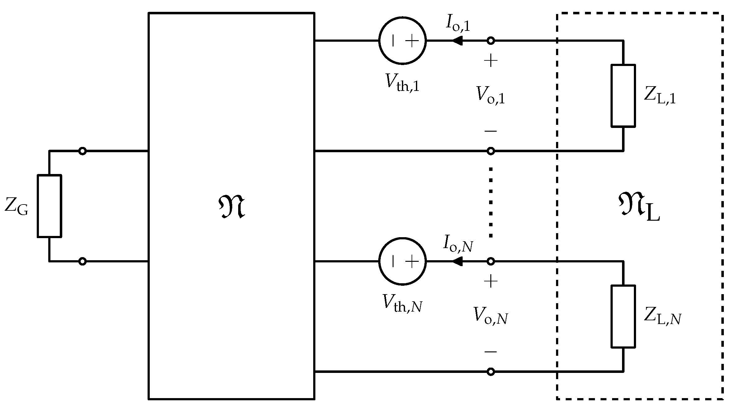
, the relation between voltages and currents at the output ports can be cast in the form
where
is a set of
N Thévenin equivalent voltage sources and
is the equivalent impedance matrix of the network
with the input port closed on the impedance
. The network
can be thus represented by the equivalent circuit of
Figure 2.
The maximum power transfer between the source and the input port of
can be achieved when the conjugate match condition
where
denotes conjugation, is satisfied. In this case, the power delivered to
is equal to the generator available power
As far as the output side is concerned, it can be proved [
31] that the power delivered by
is maximized when the output currents
assume the values
given by
where
denotes conjugate transpose, and consequently the available power at the output ports of
is
It can be noted that for
, the optimal load is not univocally defined. In fact, the optimal currents can be obtained by any impedance matrix
such that
where
are the voltages at output ports for
. Equation (
13) also shows that it is possible to realize
as a set of
N independent passive impedances provided that the possible zero elements of
corresponds to zero elements of
, and that the phase difference between any two corresponding elements of
and
is ≥
in absolute value.
According to the previous discussion, also the problem of determining the impedances and which provide the simultaneous maximum power transfer at the input and output ports has not a unique solution.
To simplify the calculation of the optimal terminations, it is convenient to determine the corresponding optimal currents, which, on the contrary, are univocally defined.
Making use of (
2), the total power delivered to the loads
, i.e., the sum of the powers delivered to each load
can be expressed as a function of the port currents as
and, similarly, the input power can be expressed as
The previous equations can be cast in the form
where the matrices
and
are defined as
The power gain of
, defined as the ratio between the output and the input power, can thus be expressed as
In the context of WPT the quantity expressed in (
20) is usually referred to as the efficiency of the link, in this paper it will be referred to as
in analogy with the terminology adopted in the context of two-port networks.
The power gain is maximized when the maximum power transfer is realized at the output port. Since is a generalized Rayleigh quotient, the maximum of can be determined by solving a generalized eigenvalue problem.
As a matter of fact, using the quotient rule and taking into account the fact that
and
are Hermitian matrices, the differential of
can be calculated as
Hence, requiring
yields
which can be rewritten as
and can be recognized as a generalized eigenvalue problem with
being the eigenvalue and
the corresponding eigenvector.
Since, by hypothesis,
is passive and the power supply is provided only at the input port, the maximum power gain,
, and the corresponding currents (up to an arbitrary factor) can be determined by solving (
23) with the constrains
After determining the optimal currents
by (
23), the corresponding voltages
can be obtained by (
2). Hence the source impedance providing maximum power transfer at the input port can be calculated by letting
while the maximum power transfer at the output port is obtained with any load
whose impedance matrix satisfies (
13). In particular, if the previously enunciated conditions are satisfied,
can be realized as a set of uncoupled loads with impedances
with
.
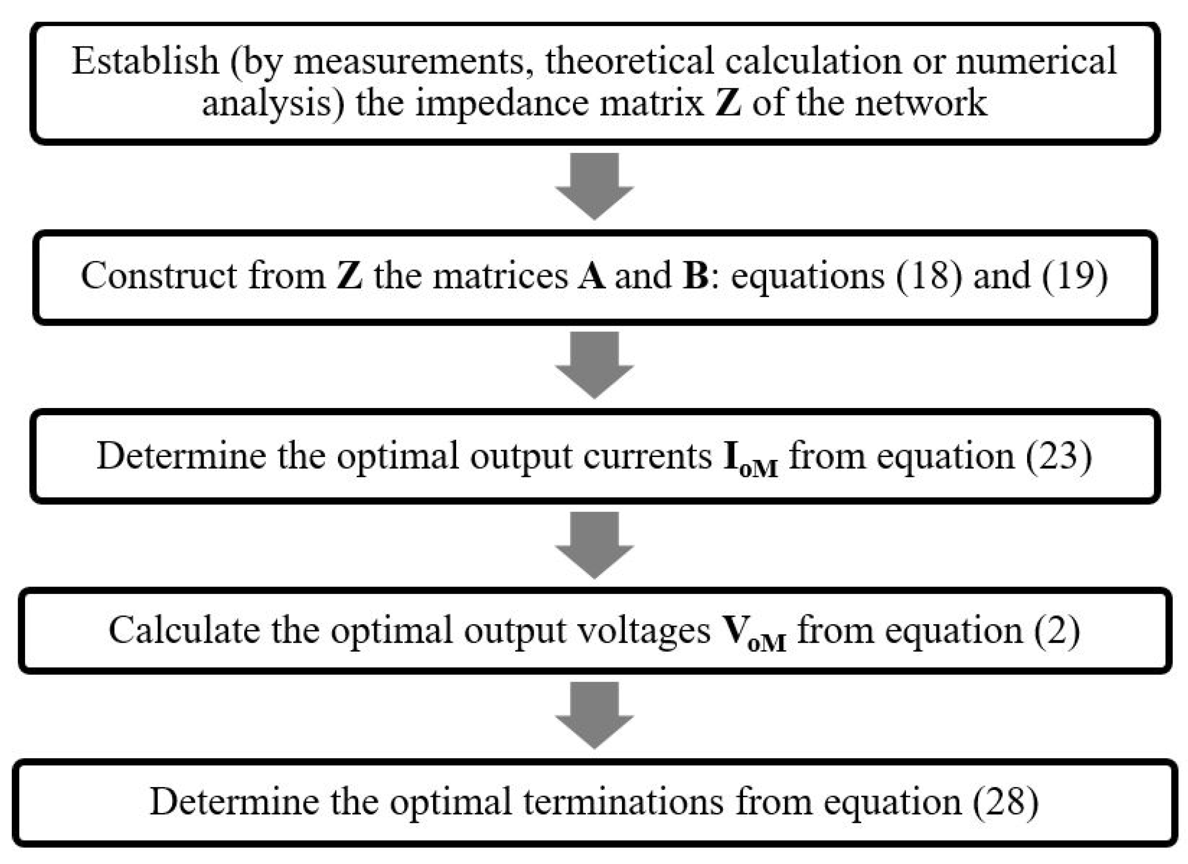
It is worth observing that the theory presented in this section is completely general, it can be applied to any passive SIMO network; moreover, for its application it is sufficient to know the impedance matrix of the network. It is possible to derive the maximum achievable power gain and the optimal loads starting from the impedance matrix, which can be the results of measurements, theoretical calculation or a numerical analysis.
Figure 3 summarizes how to apply the proposed approach for the determination of the load impedances maximizing the efficiency of a SIMO Resonant Inductive WPT Link.
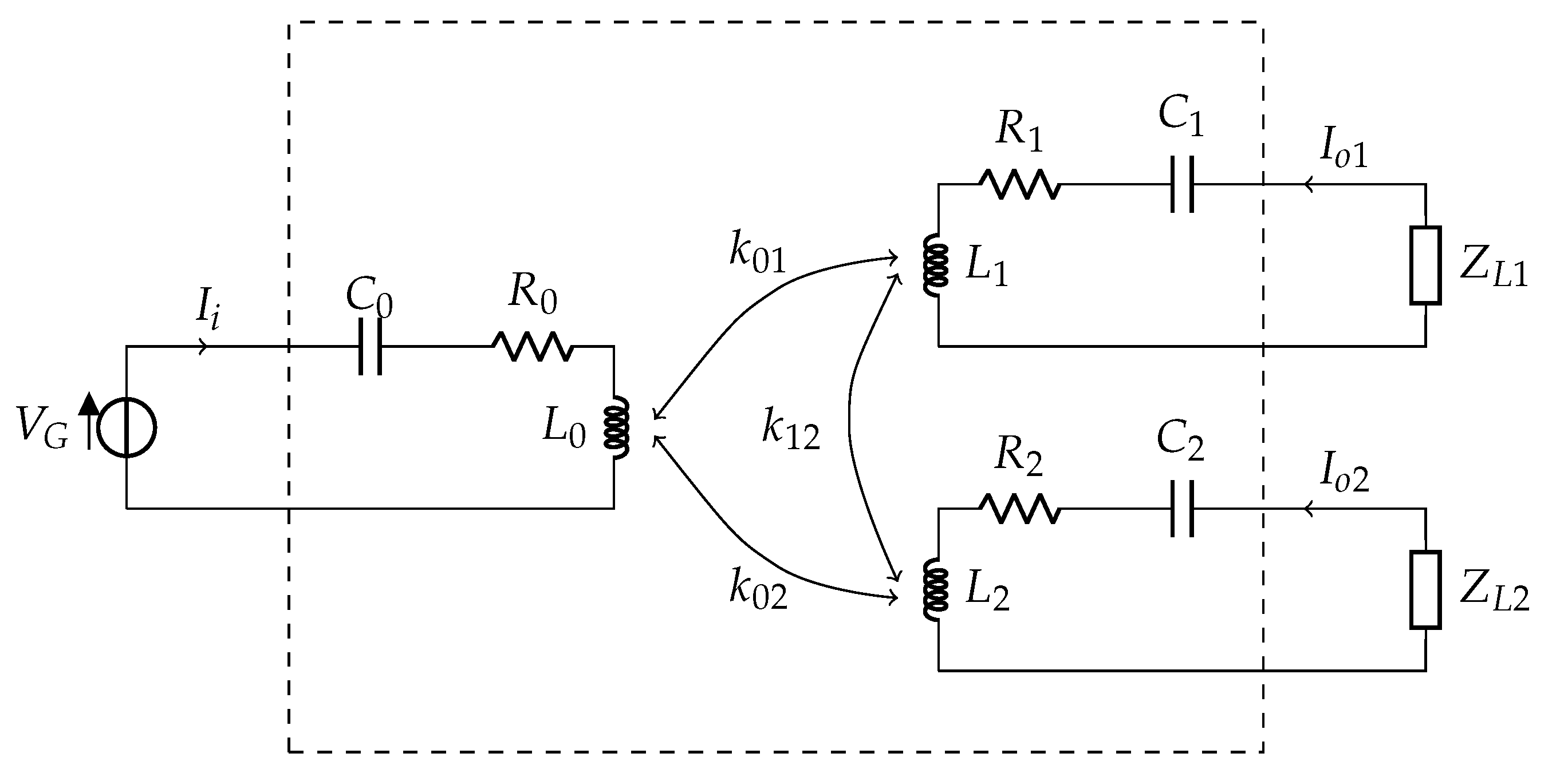
3. The Case of an Inductive Resonant Coupling
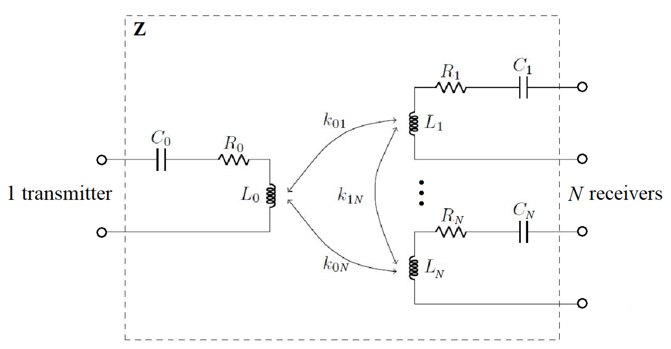
In this section, the specific case of a WPT link consisting of
magnetically coupled resonators is considered (
Figure 4). More specifically, the link consists of
magnetically coupled inductors,
, each one loaded by a suitable compensating capacitor,
, realizing the resonance condition at the operating angular frequency (i.e.,
). The inductor losses are modeled by series resistors
related to the quality factors of the coupled resonators:
The coupling between the inductors
and
is described by the coupling factor
related to the mutual inductance
Accordingly, the network is described by the following impedance matrix:
By introducing the normalization matrix
:
it is possible to obtain the following normalized expression for the impedance matrix of the network:
Referring to
Section 2 and to the
Appendix A, for the specific analyzed case it is possible to derive:
and
Accordingly, by introducing the parameter
:
for the analyzed case, the solving equation is (see the
Appendix A):
Equation (
37) has two eigenvalues:
It is evident that
; as a consequence, only
satisfies the first constrain expressed in (
24).
By choosing to normalize the input current to 1
the following normalized eigenvectors can be obtained
The corresponding normalized voltages are:
Hence the optimal normalized source impedance is given by:
however, the optimal N-port load network
can be realized as a set of uncoupled loads with normalized impedances:
The corresponding unnormalized expressions are:
Discussion of the Results
According to the above reported formulas, the following considerations can be drawn.
From (
38) it is evident that the maximum realizable efficiency of the link only depends on the quality factors of the resonators and on the couplings between the transmitting and the receiving resonators; however, it does not depend on the couplings among the receivers. This means that a possible coupling among the receivers can be always compensated.
In general, the optimal loads are complex quantities.
For identical resonators with the same quality factor the real part of the optimal loads is the same for all the loads.
The imaginary parts of the optimal loads are zero for uncoupled receiving resonators; this means that they play a role of compensation.
By comparing the expression of the reactive parts of the optimal loads with those of the optimal loads reported in [
21] for the maximum power case, it can be easily verified that they are coincident. This means that the same compensating reactances are required for both the maximum efficiency case (i.e., for maximizing the power gain) and the maximum power case.
The proposed approach also provides the optimal value of the generator impedance, see (
27); however,
does not depend on the generator. The value provided for
in (
27) is that maximizing the power entering the network, and then the power delivered to the loads, when the loads are those maximizing
.
It is worth observing that all the achieved results are in a perfect agreement with those reported in [
30]. With respect to previously proposed approaches, the theory presented in this paper has the advantage of being completely general, it is valid for any strictly passive and reciprocal network. Additionally, the application of the presented theory just needs the impedance matrix of the link that can be the result of measurements or simulations or theoretical evaluation. In fact, the optimal loads are obtained by solving the eigenvalue problem expressed in (
23). To solve the eigenvalue problem one just needs the matrices
and
that can be directly computed from the
matrix, see (
18) and (
19).
4. Validation of the Results
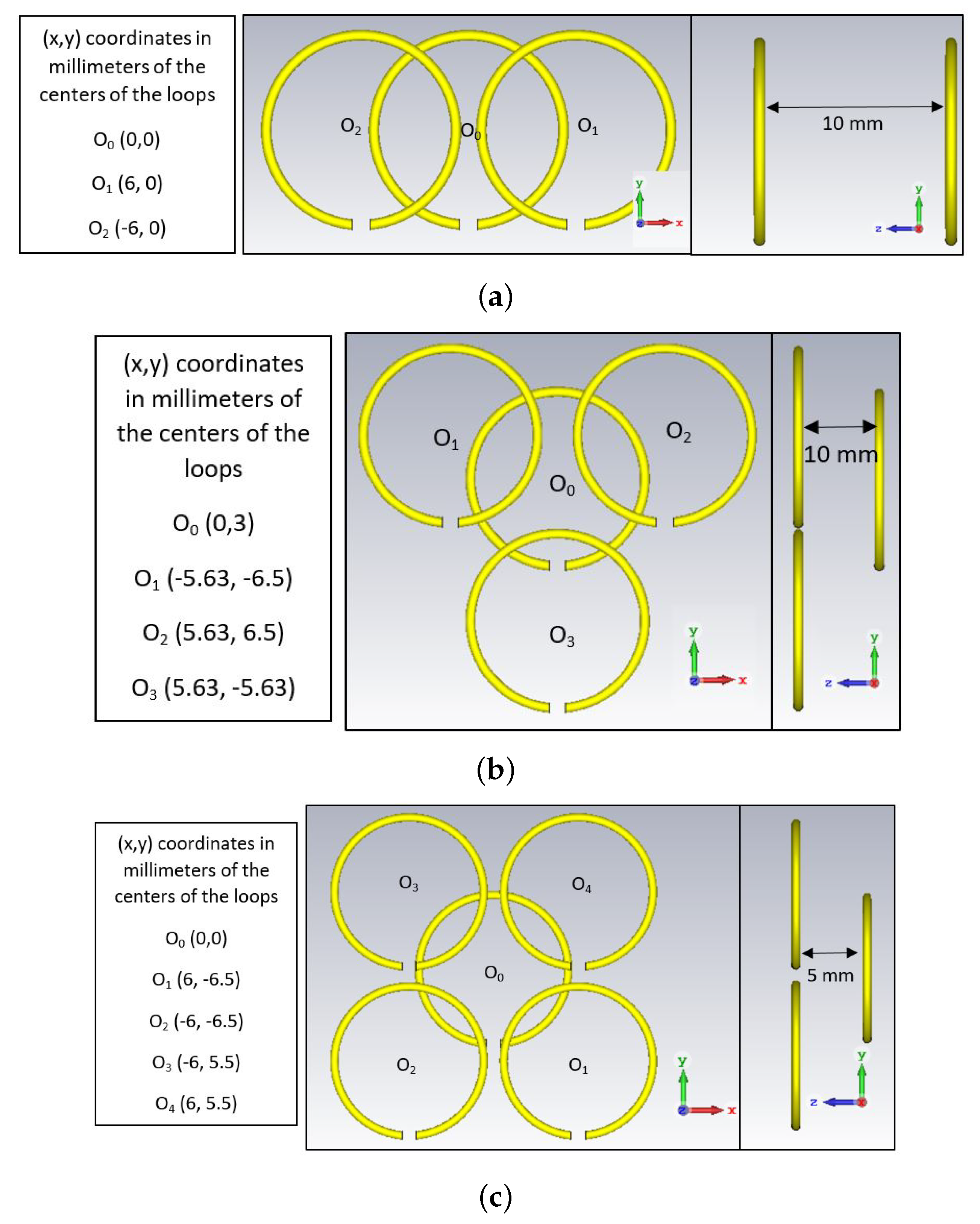
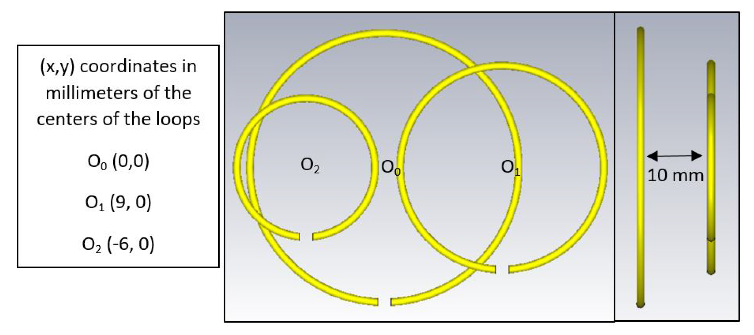
To validate the theoretical data, full-wave and circuital simulations have been performed. The commercial tool CST Microwave Studio has been used for full-wave simulations, while the NI AWR Design Environment has been adopted for circuital simulations. Four different WPT links in SIMO configuration have been analyzed. The first three analyzed cases have identical resonators and a different number of receivers, as detailed in the following.
All the analyzed coils (transmitter and receivers) have the same dimensions; they are circular loops with a radius of 5
designed by using a copper wire with a radius of
. An operating frequency
of 500
has been assumed. First, the single loop has been analyzed so to calculate the equivalent inductance. From full-wave simulations at
each loop corresponds to an inductance of about
. Accordingly, a series capacitor of
has been added to each loop so to make them resonating at
. The relative positions of the transmitting and the receiving coils assumed for the three analyzed cases are illustrated in
Figure 5.
To calculate the impedance matrices, each link has been analyzed through full-wave simulations as a multiport network. The following impedance matrices have been obtained:
By comparing the general expression of the impedance matrix of a resonant inductive WPT link given in (
31) with the numerical values calculated through circuital simulations, the values reported in
Table 1,
Table 2 and
Table 3 have been derived for the coupling coefficients. By using (
47) and (
48) it is possible to calculate the expressions of the optimal loads. The values calculated for the three analyzed examples are summarized in
Table 1,
Table 2 and
Table 3. With all the resonators the same quality factor, the resistive part of the loads is the same for all the receivers.
As per the imaginary parts, for the analyzed cases all the calculated values of are negative, thus corresponding to load impedances with an inductor in series configurations with the resistive part .
The analytical values of the optimal loads have been validated through circuital simulations.
Two different sets of circuital simulations have been performed. A first set of simulations has been performed by modeling the links with lumped elements equivalent circuits with the parameters summarized in
Table 1,
Table 2 and
Table 3;
Figure 6 illustrates the circuit analyzed for case 1. The resistors
that appear in
Figure 6 are related to the quality factors of the resonators,
, through (
29). A second set of simulations has been performed by modeling the analyzed links as
–port black–box networks described by the impedance matrices provided by full–wave simulations, being
N the number of receivers (i.e.,
for case 1,
for case 2,
for case 3). In more detail, referring to case 1, simulations have been performed by replacing the network in the dashed square of
Figure 6 with a three–port black-box component described by the impedance matrix of the link calculated through circuital simulations.
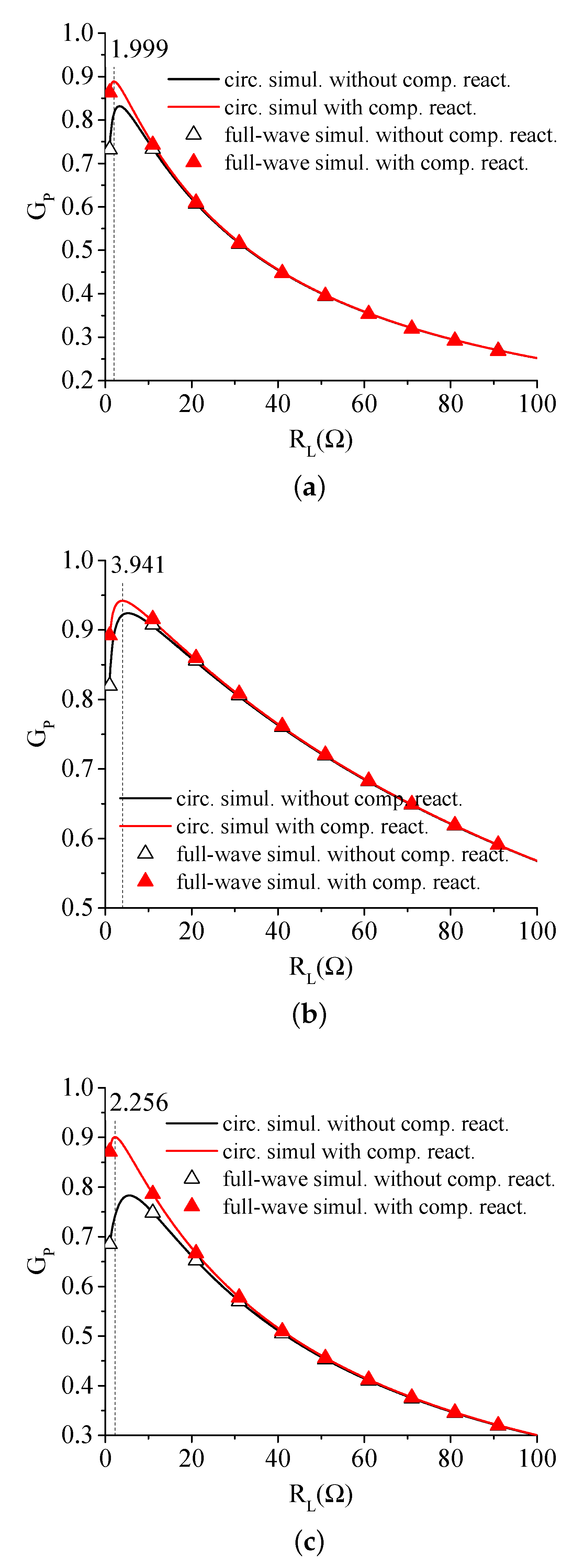
First, the optimal values provided by the theory for the resistive parts of the loads have been validated. Simulations have been performed by varying the resistive part of the loads, the values calculated for
are given in
Figure 7a–c.
The results obtained for the case of purely resistive loads (i.e.,
) are compared with those obtained for the case of loads with the compensating inductances given in
Table 3, i.e., for
. In the figures, the triangles have been used for the results obtained by modeling the link with the impedance matrix provided by full-wave simulations; however, the solid lines have been used for the results obtained by modeling the links with the lumped elements equivalent circuit. It can be seen that the results obtained for the two representations of the links are coincident.
As per the optimal values of , in each figure the value of for which is maximized is highlighted by a dashed vertical line. It can be seen that the values calculated through circuital simulations confirm the theoretical values. Finally, with regard to the compensating inductances , it seems that they play a more or less important role in maximizing depending on the analyzed case. For instance, according to the achieved results the compensating reactances play a marginal role in maximizing for case 2 while they seem to be more relevant for case 3. However, for all the three analyzed cases it is confirmed that their presence allows obtaining the maximum value of provided by the theory.
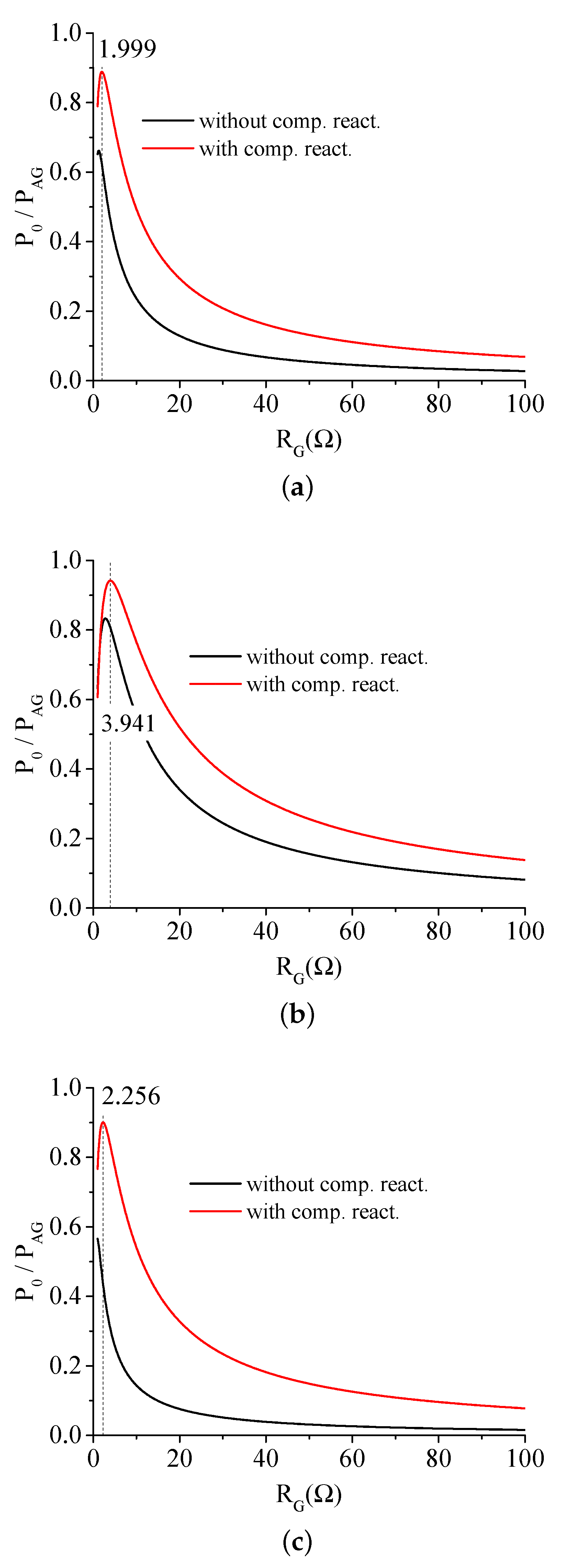
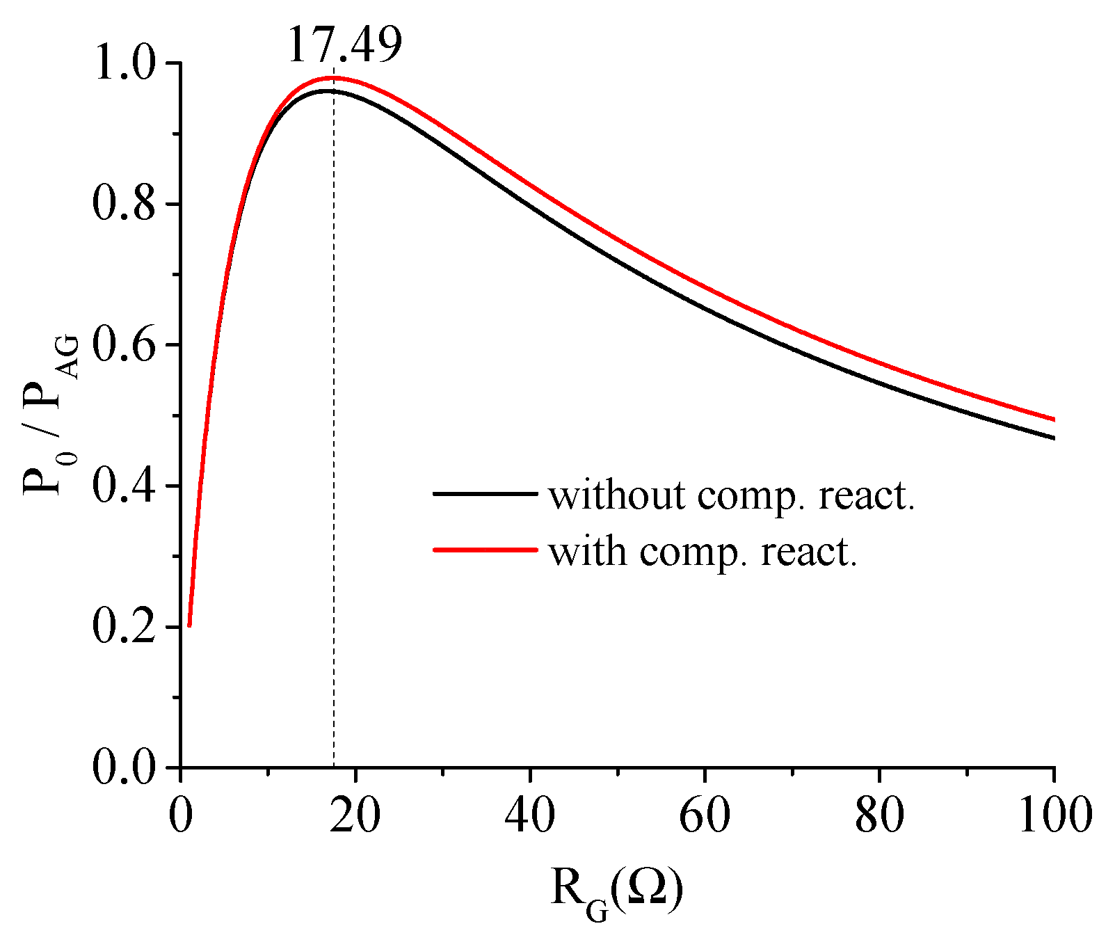
The behavior of the power delivered to the loads as function of the generator impedance has been also investigated. Simulations have been performed by using as source a voltage generator with a series impedance
. The total output power has been calculated by varying
when the loads assume the optimal values provided by the theory. The results are given in
Figure 8a–c, data obtained for
and
are compared. The dashed vertical lines highlight the values of
maximizing
for the case
. It can be verified that these values are in a perfect agreement with the optimal values provided by the theory. As it can be seen, the use of the generator impedance provided by (
43) allows maximizing the power delivered to the loads when they are set to maximize
. Additionally, it can be seen that the compensation reactances are crucial to maximize the power transferred to the loads.
It is worth observing that the output power illustrated in
Figure 8a–c is the total output power delivered (i.e., the sum of the power delivered to the loads) when the network operates at maximum
. From the figures it is evident that if
is not optimized, although the network operates with efficiency values close to one, only a small portion of the power available from the generator is delivered to the load.
Finally, the case of a link consisting of three coils with different dimensions has been analyzed (case 4). The geometry analyzed through full-wave simulations is illustrated in
Figure 9. All the coils have been designed by using a copper wire with a radius of
. The radius of the transmitting coil is 10
, those of the first and second receivers are
and 5
, respectively. Also, in this case an operating frequency
of 500
has been assumed.
The impedance matrix as calculated from full-wave simulations is:
The parameters derived for the equivalent circuit are summarized in
Table 4.
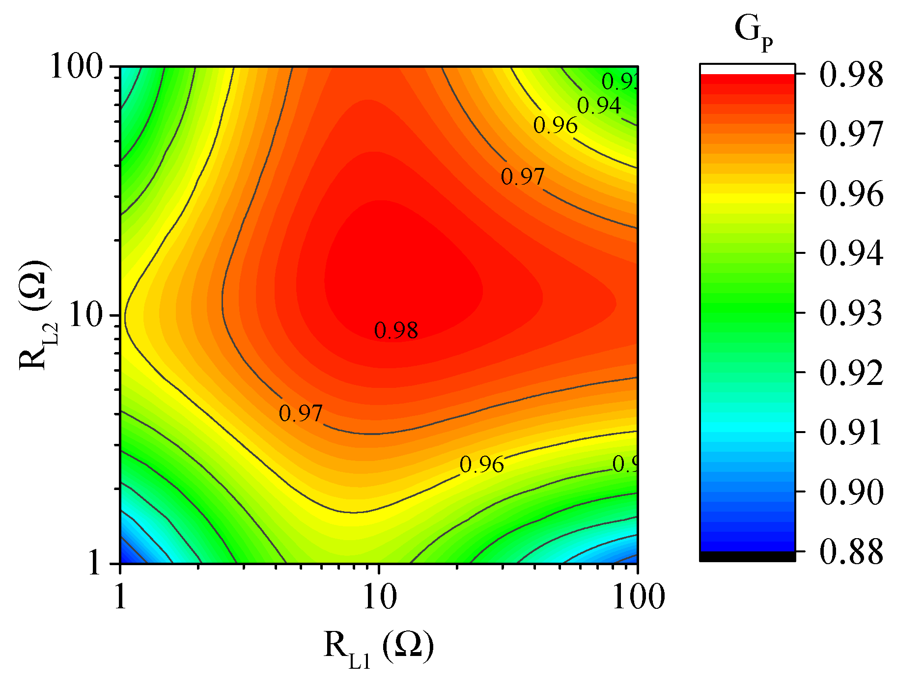
The simulated results obtained for
are illustrated in
Figure 10. Circuital simulations have been performed by modeling the link as a three–port black–box component described by the impedance matrix calculated through full–wave simulations. In this case, the two receivers have slightly different values of the quality factors; accordingly, the theory predicts slightly different values for
and
. To verify the expected optimal values, simulations have been performed by terminating the receivers ports on the impedances
and
and by varying both
and
. From
Figure 10 it can be seen that circuital simulations confirm the theory, a maximum of about 0.98 is obtained for
when
and
; however, from the figure it can also be seen that values of
very close to its maximum (i.e., values greater than 0.97) are obtained for a wide range of values of
and
.
Finally, the behavior obtained for the total output power
as function of the generator impedance is illustrated in
Figure 11. In this case, simulations have been performed by terminating the ports of the receivers on the optimal load impedances, i.e.,
and
. As for the previously analyzed cases, simulations confirm the importance of suitably selecting the generator impedance for maximizing
when the loads are those maximizing
.
5. Conclusions
In this paper, the case of a WPT link using a Single-Input Multiple-Output (SIMO) configuration is analyzed. The solution for maximizing the efficiency is derived from a generalized eigenvalue problem. The main advantage of the presented theory is its complete generality, no specific assumptions are made about the link. In fact, the proposed approach is valid for any strictly passive and reciprocal –port network. Additionally, the desired solution can be derived directly from the impedance matrix with simple algebraic operations. Theoretical formulas for the optimal loads maximizing the efficiency are derived for the case of a resonant inductive link with a generic number N of possibly coupled receivers.
The results obtained this way for the optimal loads are coincident with those reported in the previous literature were the first-order condition on the partial derivatives of the efficiency has been exploited in order to find the desired solution. As a further validation of the derived formulas, several numerical examples have been analyzed through full–wave and circuital simulations. In particular, four different links have been considered. The first three analyzed links use identical resonators for the transmitter and the receivers and differ for the number of receivers. The last analyzed case is a link using two receivers; in this case, the three resonators have been designed so to have different values of the equivalent inductance. More specifically, the transmitter has been designed so to have a larger inductance with respect to the receivers, so to obtain higher values of the couplings with respect to the previously analyzed cases. For all the investigated cases, the impedance matrix has been calculated through full-wave simulations and the presented theory applied so to determine the maximum realizable efficiency and the optimal terminating impedances. The correctness of the analytical data has been verified through simulations performed for evaluating the efficiency of the links. According to the theoretical data, simulations confirm that the maximum realizable efficiency of a resonant inductive link in SIMO configuration does not depend on the coupling among the receiving resonators. In fact, it is demonstrated that a possible coupling among the receivers can be always compensated by using suitable complex loads.
The possibility of maximizing the power delivered to the loads when they are set to maximize the efficiency has been also discussed. In fact, the presented theory provides both:
the expressions of the loads that maximize the efficiency,
the expression of the generator impedance that allows maximizing the power entering the network when the loads are those maximizing the efficiency.
Maximizing the power entering the network for a given efficiency corresponds maximizing the power delivered to the loads. The reported results highlight the importance of also optimizing the generator impedance to avoid that. Despite the high efficiency values, only a small portion of the power available from the generator is transferred to the loads.
As future developments of the presented research, experimental tests will be performed to verify the application of the proposed theory to a real application. Furthermore, in a future work the analysis presented in this paper will be extended to a generic MIMO (Multiple Input Multiple-Output) system.


 ,
, 


