Article

Online Rotor and Stator Resistance Estimation Based on Artificial Neural Network Applied in Sensorless Induction Motor Drive

1
Faculty of Electrical Engineering, Vinh University of Technology Education, 117 Nguyen Viet Xuan Street, Vinh City 890000, Vietnam
2
Faculty of Electrical Engineering, Wroclaw University of Science and Technology, 50-370 Wroclaw, Poland
3
Department of Computer Science and Engineering, Techno India NJR Institute of Technology Udaipur, Rajasthan 313003, India
4
Data Analytics and Artificial Intelligence Laboratory, Engineering-Technology School, Thu Dau Mot University, Thu Dau Mot City 820000, Vietnam
*
Author to whom correspondence should be addressed.
Energies 2020, 13(18), 4946; https://doi.org/10.3390/en13184946
Submission received: 5 September 2020 / Revised: 16 September 2020 / Accepted: 18 September 2020 / Published: 21 September 2020

Abstract

:
This paper presents a new approach method for online rotor and stator resistance estimation of induction motors using artificial neural networks for the sensorless drive. In this method, the rotor resistance is estimated by a feed-forward neural network with the learning rate as a function. The stator resistance is also estimated using the two-layered neural network with learning rate as a function. The speed of the induction motor is also estimated by the neural network. Therefore, the accurate estimation of the rotor and stator resistance improved the quality of the sensorless induction motor drive. The results of simulation and experiment show that the estimated speed tracks the real speed of the induction motor; simultaneously, the error between the estimated rotor and stator resistance using neural network and the normal rotor and stator resistance is very small.

1. Introduction

The problem of the sensorless indirect rotor flux control of induction motor (IM) is an important aspect in the study of induction motor drive systems [1]. In the sensorless control of a vector controlled three-phase induction motor drive, the rotor flux angle depends on the rotor resistance [2,3,4,5]. On the other hand, the rotor flux estimation is sensitive to the changes in the rotor and the stator resistance, especially in the case of the low rotational speed; the speed estimation of an induction motor again depends on the estimated rotor flux [6]. Therefore, the accuracy of the estimated rotor and stator resistance will improve the accuracy of the estimated speed and the estimated rotor flux, thereby improving the quality of the sensorless drive control [7]. In the operation of induction motor drives, the rotor resistance can vary up to 100% due to changes in temperature and rotor speed, so obtaining this information through a thermal model or temperature sensors is very difficult, especially for induction motors [8].
The rotor resistance estimation algorithms have been widely studied in the literature. The well-known approaches in recent studies are based on the following:
  • Model Reference Adaptive System (MRAS) [9,10,11],
  • Extended Kalman Filters [12,13,14];
  • Sliding Mode Control [15,16];
  • Fuzzy Logic Technique [17,18].
However, recently, different combinations and modifications have also been proposed. Interesting examples include the following:
  • One article [19] concerns a sensorless control approach for a five-phase induction motor drive. The sensorless scheme uses the sliding mode theory, which applies a sliding mode observer to estimate rotor resistance. The operation methodology of the proposed control technique is formulated using the mathematical model of the machine and the two-time-scale approach.
  • The author of [20] proposes the combination of parameter estimation-based observers with the dynamic regression extension and mixing parameter adaptation. The first framework is used to recast the flux observation task as a parameter estimation problem, for which the dynamic regressor extension and mixing method (DREM) technique is applied.
  • One article [21] proposes using carrier signal injection with minimized torque ripple for rotor resistance estimation. The proposed approach is based on the injection of a relatively low-frequency carrier signal into the reference of the rotor flux linkage magnitude as well as extraction of the induction machine’s response to the carrier signal, which is then used in a model reference adaptive system.
  • The author of [22] proposes the verification of rotor resistance identification in the field-oriented control-based drive system using the slip ring machine-based test bench. The paper proposes the torque calculations using the current stator and flux to propose the model reference adaptive system for online estimation of rotor resistance (without injection of the signal).
  • Other articles [23,24] propose an online estimated rotor resistance method using a neural network. However, the proposed method is still limited by the learning rate that is pre-selected and does not change during the rotor resistance estimation process. Therefore, if the learning rate is selected inappropriately, it will lead to a slow network training process and large network output errors. The choice of appropriate learning rate is mainly based on the experience of the researchers.
The literature also proposes several approaches to stator resistance estimation. The well-known approaches in recent studies are based on the following:
However, recently, different combinations and modifications have also been proposed. Interesting examples include the following:
  • One article [35] proposes a novel Power Quality Model Reference Adaptive System (PQ-MRAS) concept for stator resistance. It uses the active and reactive power of the machine, which is calculated using measurable signals, (e.g., stator voltage and current). The paper includes a detailed description of the proposed estimator.
  • The author of [36] proposes online identification of stator resistance based on the model reference adaptive system. In the article, the backpropagation is used to define the error between the measured and estimated value of stator current to adjust the weights of the neural network.
  • The author of [37] presents the IM model that is transformable into the adaptive observer form. In this method, stator resistance estimation leads to the overparameterization problem. The proposed solution uses the first-order approximation of the error dynamics to the adaptive observer.
  • The online stator resistance estimation methods using a neural network were studied and performed in [38]. However, in the proposed method, the learning rate must be selected and not changed during the estimation process. Consequently, this reduces its accuracy.
In this article, the authors propose a novel method to estimate rotor resistance and stator resistance using artificial neural networks with the learning rate as a function. This is an extension of previous research seeking to improve the control quality of the sensorless induction motor drive. This paper is arranged as follows. Section 2 presents the method to estimate rotor resistance using a two-layered neural network with the learning rate as a function. In Section 3, the rotor and stator resistance estimation method by using a two-layered neural network in which the learning rate is also a function is proposed. The experimental results in Section 4 have been proven with the proposed algorithm. The rotor and the stator resistance are accurately estimated, leading to the estimated speed of the motor being very close to the real speed, thus having the potential to improve the quality of the induction motor sensorless drive system. Finally, conclusions are given in Section 5.

2. Rotor Resistance Estimation Using Artificial Neural Networks

The rotor resistance estimator structure of the induction motor is based on MRAS [1,3], presented in Figure 1.
The outputs of the reference model (voltage model) are components of rotor leakage flux in the static frame:
{ ψ r α v m = L r L m [ ( V s α R s i s α ) d t σ L s i s α ] ψ r β v m = L r L m [ ( V s β R s i s β ) d t σ L s i s β ]
where σ = (1 − L2m/Ls Lr)—leakage coefficient.
Stator leakage flux has the following equations:
{ ψ s α = ( V s α R s i s α ) d t ψ s β = ( V s β R s i s β ) d t
Because the direct current (DC) voltage applied to the inverter is undulating, the integral stage in Equation (2) causes the stator leakage flux error. Therefore, it is necessary to adjust the stator leakage flux estimation using a multi-level low-pass filter [18]. From Equations (1) and (2), and through some transformations, we obtain equations used to estimate rotor flux according to the voltage model as follows:
{ ψ r α v m ( k ) = L r L m ψ s α ( k 1 ) L s L r L m 2 L m i s α ( k 1 ) ψ r β v m ( k ) = L r L m ψ s β ( k 1 ) L s L r L m 2 L m i s β ( k 1 )
On the other hand, the equations of the adaptive model (current model) are as follows:
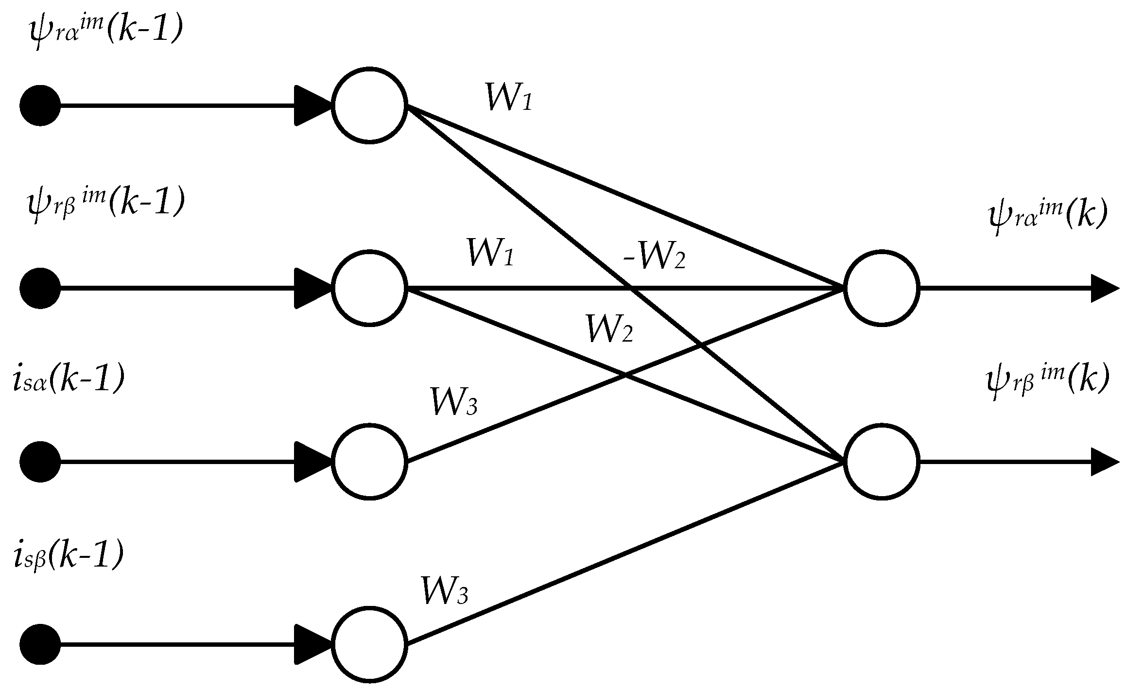
{ ψ r α i m ( k ) = W 1 ψ r α i m ( k 1 ) W 2 ψ r β i m ( k 1 ) + W 3 i s α ( k 1 ) ψ r β i m ( k ) = W 1 ψ r β i m ( k 1 ) + W 2 ψ r α i m ( k 1 ) + W 3 i s β ( k 1 )
where W 1 = 1 T s T r , W 2 = ω r T s , W 3 = T s T r L m .
Ts is the sampling time and Tr = Lr/Rr is the rotor time constant. W2 does not depend on the rotor time constant. It can be seen that the weights W1 and W3 depend on the rotor time constant. If the Lr rotor self-inductance is not changed, the weights W1 and W3 will be updated based on the rotor resistance to obtain high efficiency.
The two-layered neural network used to estimate rotor flux by the current model is illustrated in Figure 2.
The square function of rotor flux error calculated from the two models according to Equations (3) and (4) is written as follows:
E 1 = 1 2 ε ¯ 2 ( k ) = 1 2 { ψ r v m ¯ ( k ) ψ r i m ¯ ( k ) } 2
The weights of the networks W1, W3 are obtained from the network training that minimizes the square function E1 [1,9]. W1, W3 are determined as follows:
W 1 ( k ) = W 1 ( k 1 ) + η 1 Δ W 1 ( k )
W 3 ( k ) = W 3 ( k 1 ) + η 3 Δ W 3 ( k )
where
Δ W 1 ( k ) = E 1 / W 1 = [ ψ r v m ¯ ( k ) ψ r i m ¯ ( k ) ] T   ψ r i m ¯ ( k 1 )
Δ W 3 ( k ) = E 1 / W 3 = [ ψ r v m ¯ ( k ) ψ r i m ¯ ( k ) ] T   i s ¯ ( k 1 )
where the learning rates η 1 and η 3 are pre-selected constants.
The problem is to replace the constant learning rate with a function so that after each update of the weight adjustment, the error E1 value will be reduced with ς i ( k ) = Δ W i ( k ) Δ W i ( k 1 ) , where the function ς i ( k ) is the error product of the weight adjustment Wi at times k and (k−1). From this, we build the learning rate function based on the function ς i ( k ) so that the learning rate changes in the direction of reduction of the error E1 of the neural network. This means that if ς i ( k ) is positive, the neural network has a slow convergence speed and must increase the learning rate; if ς i ( k ) is negative, the learning rate must be reduced. Consider the following function:
f ( ς i ) = s i g n ( ς i ) α 0 1 + e ς i s i g n ( ς i )
The derivative of f ( ς i ) is f ( ς i ) ς i = α 0 e ς i s i g n ( ς i ) ( 1 + e ς i s i g n ( ς i ) ) 2 > 0 , where α 0 is positively identified. Here, f ( 0 ) = 0 , so ς i ( k ) f ( ς i ( k ) ) > 0 for every ς i ( k )   0 . So, the function is f ( ς i ) congruent and homologous to the error ς i . Therefore, the learning rate function can be updated according to the following rules:
η i ( k ) = η i ( k 1 ) ( 1 + f ( ς i ( k 1 ) ) )
where η i ( k 1 ) is the learning rate at (k − 1), η i ( k ) is the learning rate at k.
The learning rate determined at (11) is different from the learning rate mentioned elsewhere [1,9].
The weights of the networks W1, W3 are adjusted by training based on Equation (6) or (7). The rotor resistance is therefore estimated according to Equation (12) or (13) as follows:
R r e s = L r ( 1 - W 1 ) T s
R r e s = L r W 3 L m T s
Rotor flux estimation from Equation (1) is sensitive to changes in the stator resistance, especially in the low-speed region. Therefore, to minimize the error in the rotor resistance estimation due to the stator resistance variation, an online stator resistance estimator will be analyzed and discussed in Section 3.

3. Stator Resistance Estimation Using Artificial Neural Networks

According to [9], we have the following equation, describing components of stator currents in the static frame:
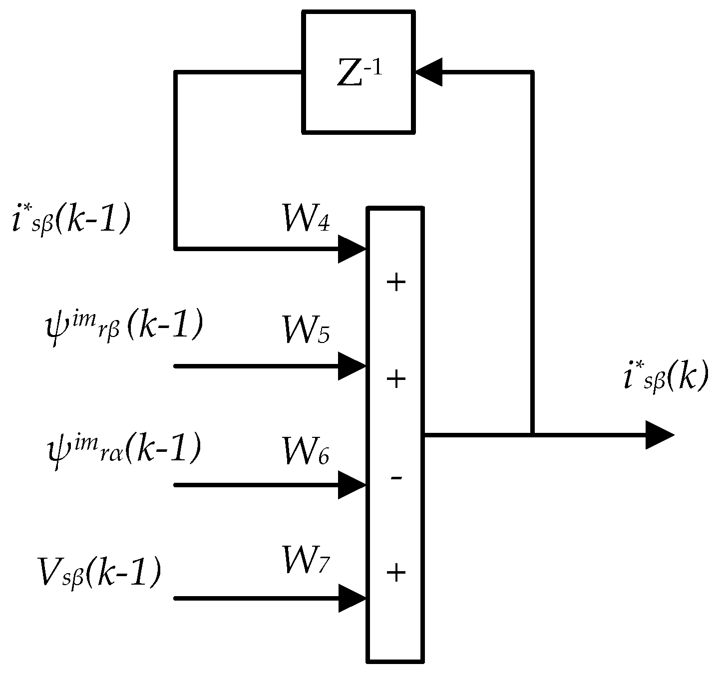
{ i s α * ( k ) = W 4 i s α * ( k 1 ) + W 5 ψ r α i m ( k 1 ) + W 6 ψ r β i m ( k 1 ) + W 7 V s α ( k 1 ) i s β * ( k ) = W 4 i s β * ( k 1 ) + W 5 ψ r β i m ( k 1 ) W 6 ψ r α i m ( k 1 ) + W 7 V s β ( k 1 )
where W 4 = [ 1 T s σ L s L m 2 L r T r T s σ L s R s ] , W 5 = T s σ L s L m L r T r , W 6 = T s σ L s L m L r ω r , W 7 = T s σ L s .
The weights W5, W6, W7 are calculated from the motor parameters, motor speed and the sampling time Ts. The weighted W4 depends on the stator resistance. The weight W4 is the adjustment weight.
Equation (14) can be represented by two layered artificial neural networks as shown in Figure 3 and Figure 4.
The error square function of the stator current measured against the estimated stator current according to Equation (14) is written as follows:
E 2 = 1 2 ε 2 ¯ 2 ( k ) = 1 2 { i s ¯ ( k ) i s * ¯ ( k ) } 2
The weight of the network W4 is derived from the training of the neural network so that the error square function E2 is minimal [9]. W4 is determined as follows:
W 4 ( k ) = W 4 ( k 1 ) + η 4 Δ W 4 ( k )
where
Δ W 4 ( k ) = E 2 W 4 = [ i s ¯ ( k ) i s * ¯ ( k ) ] T   i s * ¯ ( k 1 )
Similarly to the method of constructing the learning rate function to estimate rotor resistance in Section 2, the learning rate is updated as follows:
η 4 ( k ) = η 4 ( k 1 ) ( 1 + f ( ς 4 ) )
where
ς 4 ( k ) = Δ W 4 ( k ) Δ W 4 ( k 1 )
The learning rate determined in Equation (18) is different from the learning rate mentioned in [6,9]. Afterward, the stator resistance can be estimated as follows:
R s e s = { 1 W 4 ( T s / σ L s ) ( L m 2 R r e s / L r 2 ) } ( σ L s / T s )
The speed estimation used in sensorless drive in this paper is shown after [19], according to Expression (21) below:
ω r _ e s ( k ) = ω r _ e s ( k 1 ) + η w T s ( [ ψ r β v m ( k ) ψ r β i m ( k ) ] ψ r α i m ( k 1 ) [ ψ r α v m ( k ) ψ r α i m ( k ) ] ψ r β i m ( k 1 ) )
where η w is the learning rate for estimating rotor speed.

4. Results

4.1. Analysis

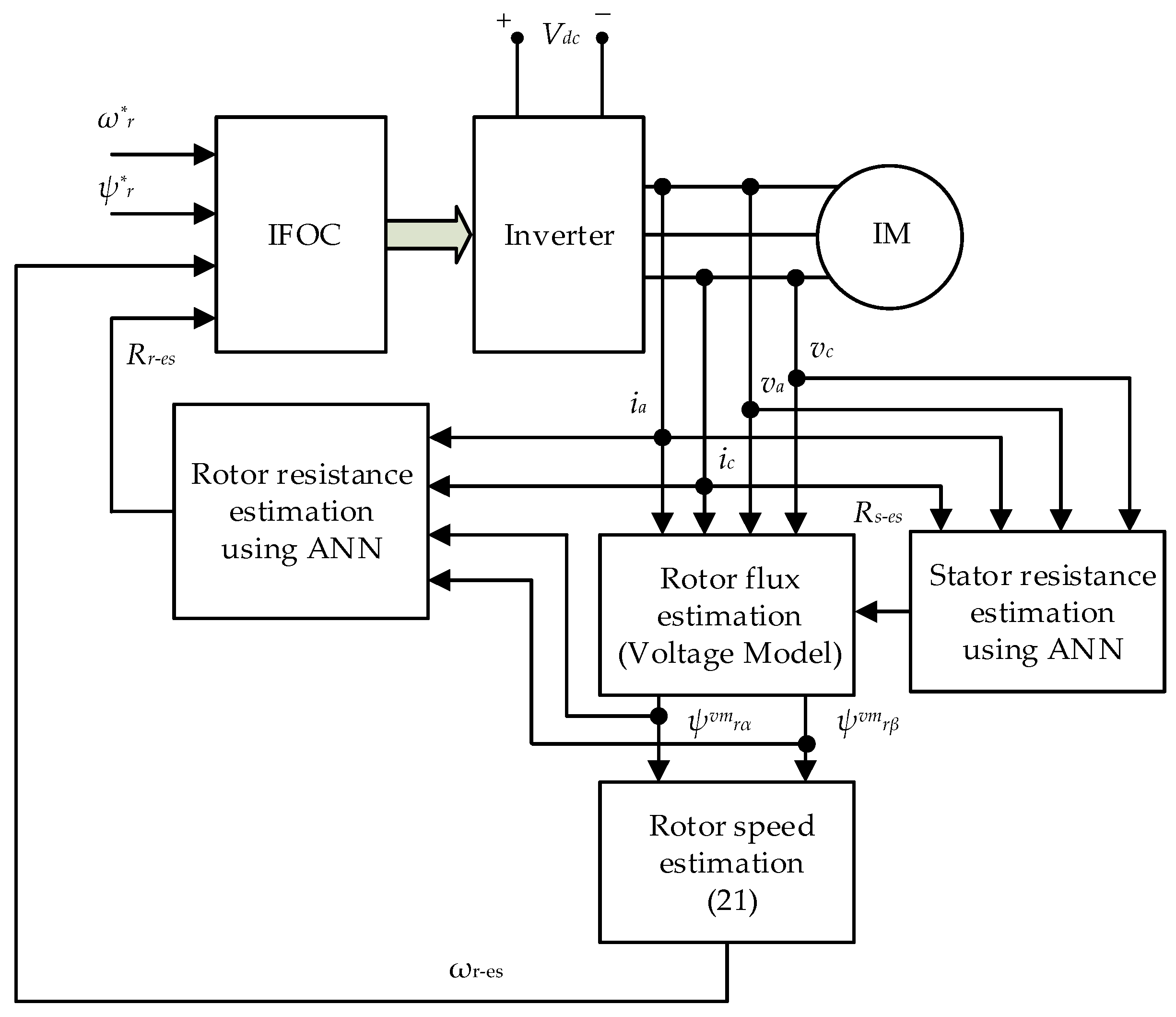
At the low-speed region, the rotor flux estimation from Equations (3) and (4) is very sensitive to stator and rotor resistance [9]. Therefore, online rotor and stator resistance estimation in Section 2 and Section 3 will improve the quality of the sensorless drive control, especially for low speeds. A diagram of the IFOC (indirect field-oriented control) sensorless drive with online rotor and stator resistance estimation is shown in Figure 5.

4.2. Results of the Simulation

To simulate a sensorless drive system with rotor and stator resistance estimation, the authors used MATLAB/Simulink software (2019a, MathWorks, Natick, MA, USA).
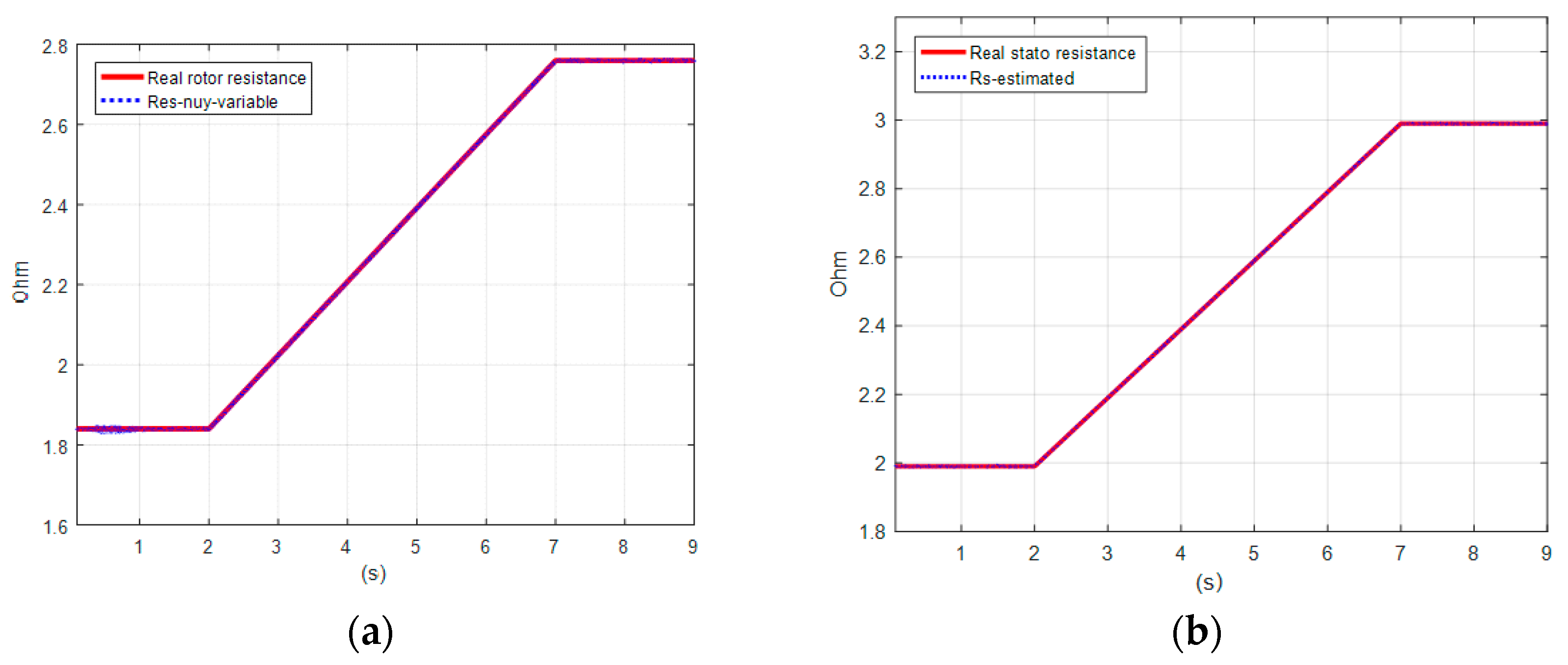
During the simulation, the rotor and stator resistances differ by 50% from the original values [1,4,9], thus leading to a discrepancy between the actual rotor and stator resistance values and real values. The rotor resistance of the induction motor varies from 1.84 to 2.76 Ω, the stator resistance of the motor varies from 1.99 to 2.99 Ω (simulation process duration 0–9 s); load TL = 2.0 Nm is applied at time t = 1.5 s. The induction motor parameters are given in Table 1.

4.2.1. Speed of Induction Motor without Rotor and Stator Resistance Estimation

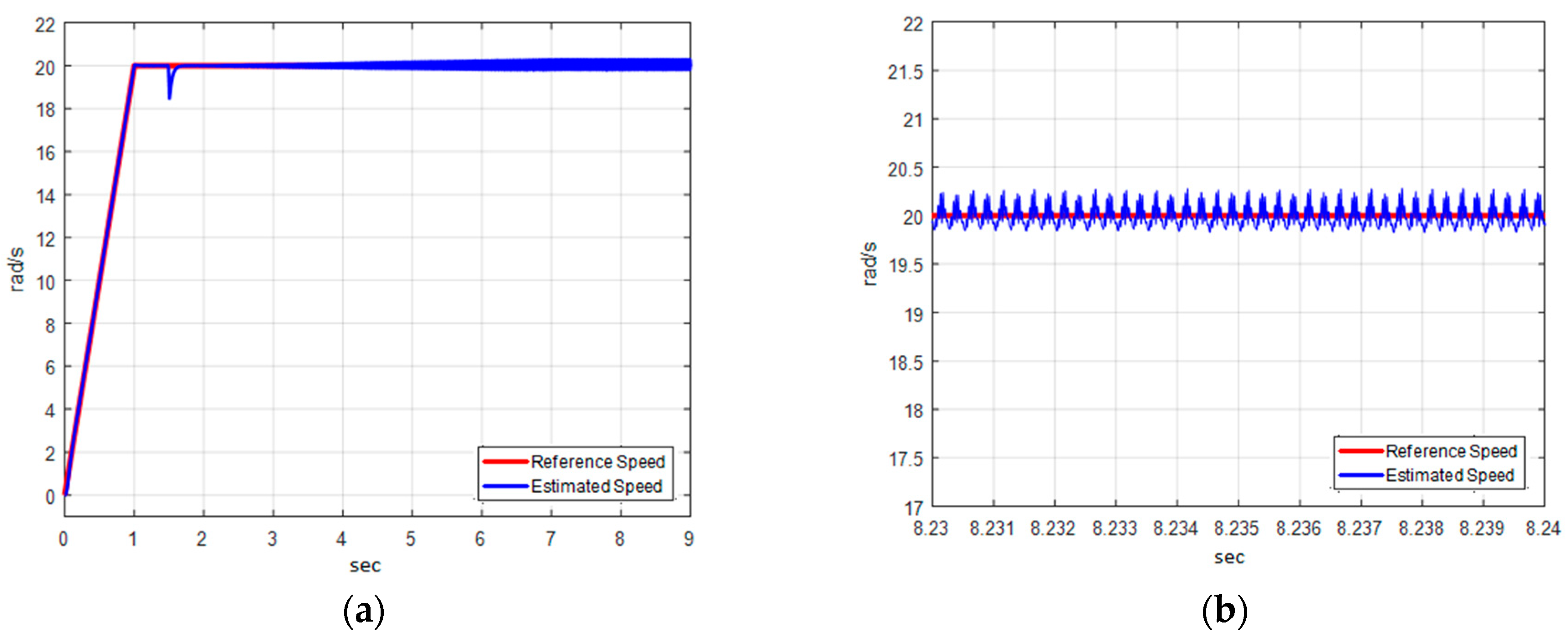
Assuming that the rotor resistance increases from 1.84 to 2.76 Ω, from 0–2 s, it remains 1.84 Ω; in 2–7 s, it increases from 1.84–2.76 Ω; at 7–9 s, the rotor resistance is 2.76 Ω. The stator resistance varies from 1.99 to 2.99 Ω for 0–2 s, it remains 1.99 Ω, at 2–7 s and it increases from 1.99–2.99 Ω for 7–9 s then stays at 2.99 Ω, but the rotor and stator resistances set for the controller retain their rated resistance values. Figure 6a indicates reference speed and estimated speed throughout the simulation time. In Figure 6b, the stator and rotor resistance values differ by 50% from the initial cold resistance values; the average estimated speed is still 20 rad/s but the pulsation of the speed is nearly 0.3 rad/s.

4.2.2. Speed of Induction Motor with Online Rotor and Stator Resistance Estimation

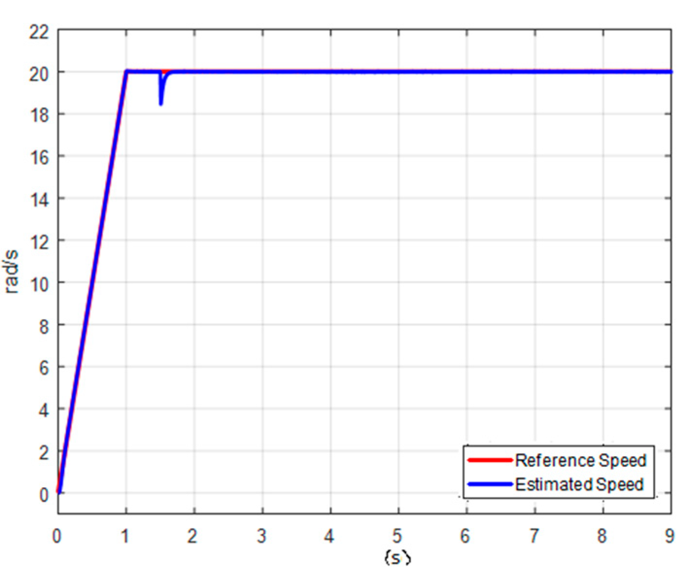
The simulation results in Figure 7a,b show that, with the resistance estimation algorithms proposed in Section 2 and Section 3, the rotor and stator resistance were accurately estimated with very small error compared to real resistance values. On the other hand, the accurate estimation of rotor and stator resistances improved the estimation of the real speed of the rotor (Figure 8), thereby improving the quality of the sensorless drive system.

4.3. Results of the Experiment

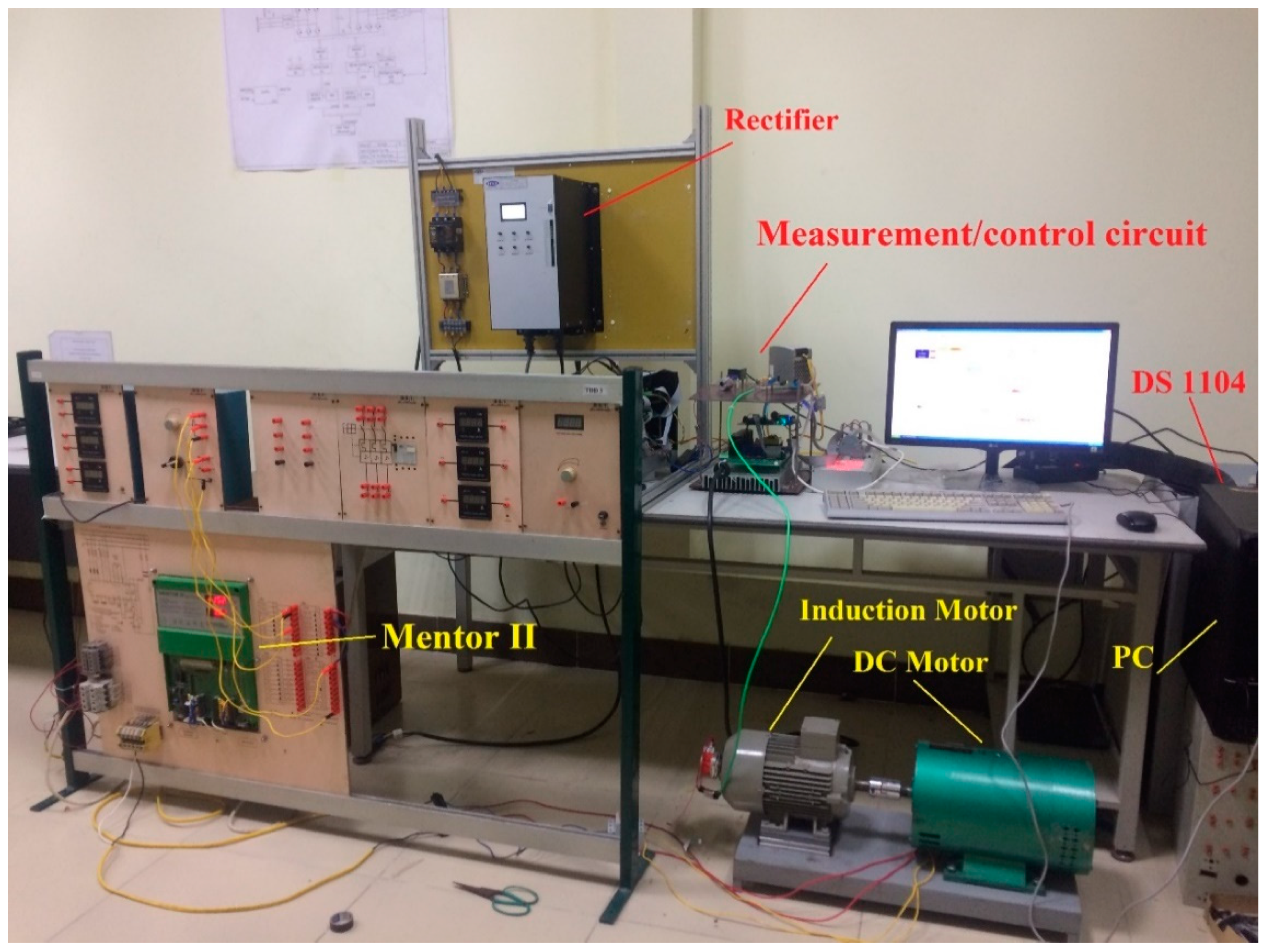
To re-examine the proposed stator and rotor resistance estimation algorithms, an experimental setup has been developed (Figure 9 and Figure 10). The experiment was performed on DS 1104 connected to the personal computer. Application of the controller is known in the literature for control of electronic converters, as in [39,40]. In this study, we use a three-phase induction motor 2.2 kW/400 V—detailed data are shown in Table 1. The motor is controlled by an inverter and is rigidly connected to a 1.5 kW dc motor—detailed data are shown in Table 2. The DC motor is controlled by a 4Q rectifier (Mentor II) in torque control mode (Torque Control) so that the load torque can be applied to the three-phase induction motor.
The current and flux controllers were implemented with a sampling time of 0.2 ms. The speed estimator using the sampling time is 2 ms, the rotor resistance estimation using the sampling time is 44 ms, the stator resistance estimation using the sampling time is 88 ms. An encoder with 5000 pulses/cycle was used to determine position and speed. The load torque is 2 Nm.
In the low-speed region, the sensorless drive is more affected by the rotor and stator resistance estimation error than in the high-speed zone [9], so in this experiment, a low speed 20 rad/s is set as the reference speed value for the controller. After a number of tests, the learning rate to estimate rotor and stator resistance was chosen as follows: ηr = 0.015; ηs = 0.022. The motor runs for some time (around 60 min or more) with a load TL = 2 Nm (approximately 30% of the rated load). The obtained results are presented as follows:
  • In Section 4.3.1, the comparison between estimation level with and without constant learning rate;
  • In Section 4.3.2, the comparison between the speed of induction motor with and without online rotor and stator resistance estimators;
  • In Section 4.3.3, the short discussion of obtained results is presented.

4.3.1. Results of Rotor and Stator Resistance Estimation

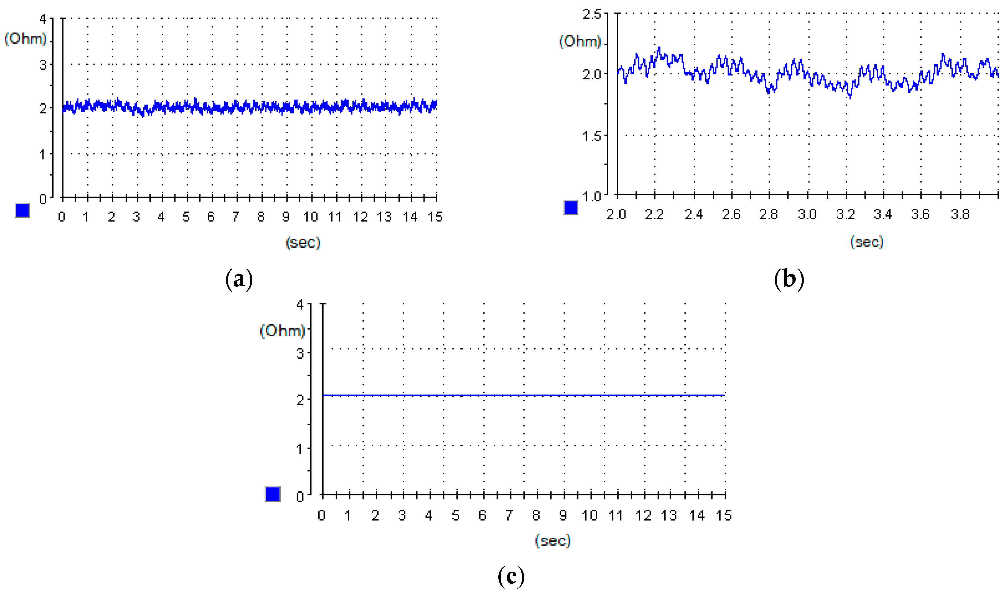
Figure 11a shows that the estimated rotor resistance with constant learning rate has an average value ≈ 2.10 Ω. Figure 11b is an enlarged image of the rotor resistance estimation with constant learning rate, the estimated rotor resistance with constant learning rate, the pulsation of estimated resistance ≈ 20%. The estimated rotor resistance using the learning rate by function (11) is almost non-pulsating, as indicated in Figure 11c. Figure 12a shows that the estimated stator resistance has an average value ≈ 2 Ω. In Figure 12b, the estimated stator resistance using the learning rate according to (18) is more accurate than using the constant learning rate (the pulsation of estimated stator resistance is ≈25% when the learning rate is constant, while with the proposed method, the pulsation of estimated stator resistance is ≈3%).

4.3.2. Impact of Online Rotor and Stator Resistance Estimation

Case study 1: Without the online rotor and stator resistance estimation.
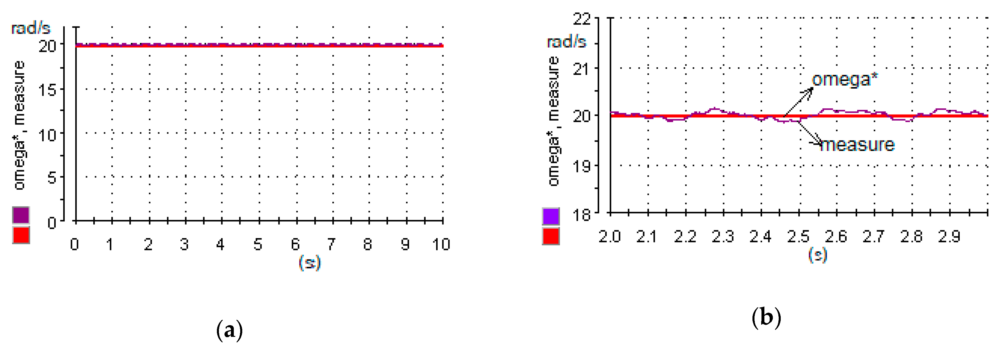
Figure 13a–d show that the measured speed is pulsating compared to the reference speed: the pulsation of measured speed is ≈5%; the estimated speed fluctuates around the reference speed; the pulsation of estimated speed is ≈6.25%.
Case study 2: With the online rotor and stator resistance estimation.
Figure 14a–d show that the measured speed is almost the same as the reference speed, and the pulsation is only ≈2%; the estimated speed also follows the reference speed, with the same pulsation of ≈2%.

4.3.3. Discussion

The results presented in the previous section indicate that
  • Estimated rotor resistance obtained from the proposed methodology ensures that the pulsation is 20% lower than with constant learning rate. Additionally, the level of pulsation of the proposed method is less than 1%, which is better than results obtained in, e.g., [16] (up to 5%);
  • Estimated stator resistance obtained from the proposed methodology ensures that the pulsation is 22% lower than with constant learning rate. Additionally, the level of pulsation of the proposed method is less than 3%, which is better than results obtained in, e.g., [35] (not exceeding 10%);
  • Application of the proposed online rotor and stator resistance estimation ensured a decrease in the value of pulsation of over 4% than with constant learning rate.
The indicated results concern the quasi-steady operating state of the drive. Analysis of other operating states is an element for future research.

5. Conclusions

This paper proposes a method for estimating the rotor and stator resistance of an induction motor using artificial neural networks with the variable learning rate determined by a function. The results show that online rotor and stator resistance estimation using the proposed method is more accurate when estimating at a constant learning rate and also demonstrate that the online estimation of rotor and stator resistance has contributed to improving the control quality of the sensorless induction motor drive. Future direction of the research will be properties evaluation of the proposed method for various operating states.

Author Contributions

Conceptualization, T.P.V. and D.V.T.; methodology, T.P.V. and D.V.T.; software, T.P.V. and D.V.T.; validation, M.J., T.S. and P.C.; formal analysis, T.P.V. and D.V.T.; investigation, T.P.V. and D.V.T.; resources, T.P.V. and D.V.T.; data curation, T.P.V. and D.V.T.; writing—original draft preparation, T.P.V. and D.V.T.; writing—review and editing, M.J. and P.C.; visualization, T.P.V. and D.V.T.; supervision, Z.L., M.J. and T.S.; project administration, Z.L.; funding acquisition, Z.L. All authors have read and agreed to the published version of the manuscript.

Funding

The APC was funded Chair of Electrical Engineering Fundamentals, Wroclaw University of Science and Technology.

Acknowledgments

The authors would like to thank the Electrical Drive Laboratory, Department of Industrial Automation, Hanoi University of Science and Technology for helping us to complete the experiments in this paper.

Conflicts of Interest

The authors declare no conflict of interest. The founding sponsors had no role in the design of the study; in the collection, analyses, or interpretation of data; in the writing of the manuscript, and in the decision to publish the results.

List of Symbols

ψ r α v m α-axis rotor flux linkages estimated by voltage model in the stator reference frame
ψ r β v m β-axis rotor flux linkages estimated by voltage model in the stator reference frame
ψ s α α-axis stator flux linkages in the stator reference frame
ψ s β β-axis stator flux linkages in the stator reference frame
ψ r α i m α-axis rotor flux linkages estimated by current model in the stator reference frame
ψ r β i m β-axis rotor flux linkages estimated by current model in the stator reference frame
V s α α-axis stator voltage in the stator reference frame
V s β β-axis stator voltage in the stator reference frame
i s α α-axis stator current in the stator reference frame
i s β β-axis stator current in the stator reference frame
Lmmagnetizing inductance
Lrrotor self-inductance
Lsstator self-inductance
Rsstator resistance
Rrrotor resistance

References

  1. Lascu, C.; Argeseanu, A.; Blaabjerg, F. Supertwisting Sliding-Mode Direct Torque and Flux Control of Induction Machine Drives. IEEE Trans. Power Electron. 2020, 35, 5057–5065. [Google Scholar] [CrossRef]
  2. Sathikumar, S.; Vithayathil, J. Digital Simulation of Field-Oriented Control of Induction Motor. IEEE Trans. Ind. Electron. 1984, IE-31, 141–148. [Google Scholar] [CrossRef]
  3. Gabriel, R.; Leonhard, W.; Nordby, C.J. Field-Oriented Control of a Standard AC Motor Using Microprocessors. IEEE Trans. Ind. Appl. 1980, IA-16, 186–192. [Google Scholar] [CrossRef]
  4. Takahashi, I.; Noguchi, T. A New Quick-Response and High-Efficiency Control Strategy of an Induction Motor. IEEE Trans. Ind. Appl. 1986, IA-22, 820–827. [Google Scholar] [CrossRef]
  5. Murata, T.; Tsuchiya, T.; Takeda, I. Vector control for induction machine on the application of optimal control theory. IEEE Trans. Ind. Electron. 1990, 37, 283–290. [Google Scholar] [CrossRef]
  6. Krishnan, R.; Doran, F.C. Study of Parameter Sensitivity in High-Performance Inverter-Fed Induction Motor Drive Systems. IEEE Trans. Ind. Appl. 1987, IA-23, 623–635. [Google Scholar] [CrossRef]
  7. Pal, A.; Das, S. Development of energy efficient scheme for speed sensorless induction motor drive. Int. Trans. Electr. Energy Syst. 2020, 30, e12448. [Google Scholar] [CrossRef]
  8. Chitra, A.; Himavathi, S. Investigation and analysis of high performance green energy induction motor drive with intelligent estimator. Renew. Energy 2016, 87, 965–976. [Google Scholar] [CrossRef]
  9. Mapelli, F.L.; Bezzolato, A.; Tarsitano, D. A Rotor Resistance MRAS Estimator for Induction Motor Traction Drive for Electrical Vehicles. In Proceedings of the 2012 XXth International Conference on Electrical Machines, Marseille, France, 2–5 September 2012; IEEE: Piscataway, NJ, USA, 2012; pp. 823–829. [Google Scholar]
  10. Basnet, B.; Lee, H.-H. Rotor Flux Estimation for Low Speed Induction Motor Sensorless Drives with MRAS. In Lecture Notes in Electrical Engineering; Springer: Singapore, 2018; pp. 509–518. [Google Scholar]
  11. Orlowska-Kowalska, T.; Korzonek, M.; Tarchala, G. Performance Analysis of Speed-Sensorless Induction Motor Drive Using Discrete Current-Error Based MRAS Estimators. Energies 2020, 13, 2595. [Google Scholar] [CrossRef]
  12. Ouhrouche, M.A. Estimation of speed, rotor flux, and rotor resistance in cage induction motor using the EKF algorithm. Int. J. Power Energy Syst. 2002, 22, 103–109. [Google Scholar]
  13. Lin, G.; Wan, Q. Estimation of rotor resistance of induction motor based on extended kalman filter. In Part of the Advances in Intelligent and Soft Computing Book Series; Springer: Berlin, Germany, 2012; pp. 193–198. [Google Scholar]
  14. Demir, R.; Barut, M.; Yildiz, R.; Inan, R.; Zerdali, E. EKF based rotor and stator resistance estimations for direct torque control of Induction Motors. In Proceedings of the 2017 International Conference on Optimization of Electrical and Electronic Equipment (OPTIM) & 2017 Intl Aegean Conference on Electrical Machines and Power Electronics (ACEMP), Fundata, Romania, 25–27 May 2017; IEEE: Piscataway, NJ, USA, 2017; pp. 376–381. [Google Scholar]
  15. Tak, R.; Kumar, S.Y.; Rajpurohit, B.S. Estimation of Rotor and Stator Resistance for Induction Motor Drives using Second order of Sliding Mode Controller. J. Eng. Sci. Technol. Rev. 2017, 10, 9–15. [Google Scholar] [CrossRef]
  16. Yang, S.; Sun, R.; Cao, P.; Xie, Z.; Zhang, X. Sliding-mode observer based rotor resistance updating method for indirect vector controlled induction motor. In Proceedings of the 2017 IEEE Transportation Electrification Conference and Expo, Asia-Pacific (ITEC Asia-Pacific), Harbin, China, 7–10 August 2017; IEEE: Piscataway, NJ, USA, 2017; pp. 1–5. [Google Scholar]
  17. Karanayil, B.; Rahman, M.F.; Grantham, C. Stator and Rotor Resistance Observers for Induction Motor Drive Using Fuzzy Logic and Artificial Neural Networks. IEEE Trans. Energy Convers. 2005, 20, 771–780. [Google Scholar] [CrossRef]
  18. Miloud, Y.; Draou, A. Fuzzy Logic Based Rotor Resistance Estimator of an Indirect Vector Controlled Induction Motor Drive. In Proceedings of the IEEE 2002 28th Annual Conference of the Industrial Electronics Society, Sevilla, Spain, 5–8 November 2002; IECON 02. IEEE: Piscataway, NJ, USA; Volume 2, pp. 961–966. [Google Scholar]
  19. Mossa, M.A.; Echeikh, H.; Iqbal, A.; Duc Do, T.; Al-Sumaiti, A.S. A Novel Sensorless Control for Multiphase Induction Motor Drives Based on Singularly Perturbed Sliding Mode Observer-Experimental Validation. Appl. Sci. 2020, 10, 2776. [Google Scholar] [CrossRef] [Green Version]
  20. Bazylev, D.N.; Doria-Cerezo, A.; Pyrkin, A.A.; Bobtsov, A.A.; Ortega, R. A New Approach for Flux and Rotor Resistance Estimation of Induction Motors. IFAC PapersOnLine 2017, 50, 1885–1890. [Google Scholar] [CrossRef]
  21. Hasanzadeh, A.; Reed, D.M.; Hofmann, H.F. Rotor Resistance Estimation for Induction Machines Using Carrier Signal Injection With Minimized Torque Ripple. IEEE Trans. Energy Convers. 2019, 34, 942–951. [Google Scholar] [CrossRef]
  22. Égető, T.; Farkas, B. Model Reference Adaptive System for the Online Rotor Resistance Estimation in the Slip-Ring Machine Based Test-bench. Period. Polytech. Electr. Eng. Comput. Sci. 2018, 62, 149–154. [Google Scholar] [CrossRef]
  23. Chitra, A.; Himavathi, S. A modified neural learning algorithm for online rotor resistance estimation in vector controlled induction motor drives. Front. Energy 2015, 9, 22–30. [Google Scholar] [CrossRef]
  24. Venkadesan, A.; Himavathi, S.; Muthuramalingam, A.; Sedhuraman, K. ANN based Flux Estimator for Rotor Resistance Estimation in Vector Controlled IM Drives. In Proceedings of the 2018 IEEE International Conference on System, Computation, Automation and Networking (ICSCA), Pondicherry, India, 6–7 July 2018; IEEE: Piscataway, NJ, USA, 2018; pp. 1–5. [Google Scholar]
  25. Bensalem, Y.; Abdelkrim, M.N. A Sensorless Neural Model Reference Adaptive Control for Induction Motor Drives. In Proceedings of the 2009 3rd International Conference on Signals, Circuits and Systems (SCS), New York, NY, USA, 6–8 November 2009; IEEE: Piscataway, NJ, USA, 2009; pp. 1–6. [Google Scholar]
  26. Mohan Krishna, S.; Febin Daya, J.L. An Improved Stator Resistance Adaptation Mechanism in MRAS Estimator for Sensorless Induction Motor Drives. In Proceedings of the First International Conference on Intelligent Computing and Communication. Advances in Intelligent Systems and Computing, West Bengal, India, 18–19 February 2016; Volume 458, pp. 371–385. [Google Scholar]
  27. Karthikeyan, A.; Prabhakaran, K.K.; Nagamani, C. Stator flux based MRAS speed and stator resistance estimator for sensorless PMSM drive. In Proceedings of the 2017 14th IEEE India Council International Conference (INDICON), Roorkee, India, 15–17 December 2017; IEEE: Piscataway, NJ, USA, 2017; pp. 1–6. [Google Scholar]
  28. Jouili, M.; Agrebi, Y.; Koubaa, Y.; Boussak, M. A Luenberger State Observer for Simultaneous Estimation of Speed and Stator Resistance in Sensorless IRFOC Induction Motor Drives. In Proceedings of the 2015 16th International Conference on Sciences and Techniques of Automatic Control and Computer Engineering (STA), Monastir, Tunisia, 21–23 December 2015; IEEE: Piscataway, NJ, USA, 2015; pp. 898–904. [Google Scholar]
  29. Djamila, C.; Yahia, M.; Ali, T. Simultaneous estimation of rotor speed and stator resistance in sensorless indirect vector control of induction motor drives using a Luenberger observer. Int. J. Comput. Sci. Issues 2012, 9, 325. [Google Scholar]
  30. Boulghasoul, Z.; Kandoussi, Z.; Elbacha, A.; Tajer, A. Fuzzy Improvement on Luenberger Observer Based Induction Motor Parameters Estimation for High Performances Sensorless Drive. J. Electr. Eng. Technol. 2020. [Google Scholar] [CrossRef]
  31. Ameur, A.; Kious, M.; Ameur, F.; Ameur, I.; Hadjadj, A. Speed sensorless direct torque control of a PMSM drive based type-2 fuzzy logic stator resistance estimator and luenberger observer. In Proceedings of the 2016 8th International Conference on Modelling, Identification and Control (ICMIC), Algiers, Algeria, 15–17 November 2016; IEEE: Piscataway, NJ, USA, 2016; pp. 219–224. [Google Scholar]
  32. Reza, C.M.F.S.; Islam, D.; Mekhilef, S. Stator resistance estimation scheme using fuzzy logic system for direct torque controlled induction motor drive. J. Intell. Fuzzy Syst. 2014, 27, 1631–1638. [Google Scholar] [CrossRef]
  33. Khadar, S.; Kouzou, A.; Benguesmia, H. Fuzzy Stator Resistance Estimator of Induction Motor fed by a Three Levels NPC Inverter Controlled by Direct Torque Control. In Proceedings of the 2018 International Conference on Applied Smart Systems (ICASS), Medea, Algeria, 24–25 November 2018; IEEE: Piscataway, NJ, USA, 2018; pp. 1–7. [Google Scholar]
  34. Karunathilake, K.R.R.D.K.; Ranathunga, D.S.; Kaushalya, K.L.S.; Abeyratne, S.G. Fuzzy logic based stator resistance compensation technique for PWM-VSI drives. In Proceedings of the 2015 IEEE 10th International Conference on Industrial and Information Systems (ICIIS), Sri Lanka, Sri Lanka, 17–20 December 2015; IEEE: Piscataway, NJ, USA, 2015; pp. 452–457. [Google Scholar]
  35. Bednarz. Dybkowski Estimation of the Induction Motor Stator and Rotor Resistance Using Active and Reactive Power Based Model Reference Adaptive System Estimator. Appl. Sci. 2019, 9, 5145. [Google Scholar] [CrossRef] [Green Version]
  36. Youlin, Y. A Speed Estimation Method with Stator Resistance Online Identification based on MRAS. In Proceedings of the 2019 Chinese Control And Decision Conference (CCDC), Nanchang, China, 3–5 June 2019; IEEE: Piscataway, NJ, USA, 2019; pp. 3697–3700. [Google Scholar]
  37. Chen, J.; Huang, J.; Sun, Y. Resistances and Speed Estimation in Sensorless Induction Motor Drives Using a Model With Known Regressors. IEEE Trans. Ind. Electron. 2019, 66, 2659–2667. [Google Scholar] [CrossRef]
  38. Karanayil, B.; Rahman, M.F.; Grantham, C. Online Stator and Rotor Resistance Estimation Scheme Using Artificial Neural Networks for Vector Controlled Speed Sensorless Induction Motor Drive. IEEE Trans. Ind. Electron. 2007, 54, 167–176. [Google Scholar] [CrossRef]
  39. Isen, E.; Bakan, A.F. Development of 10 kW Three-Phase Grid Connected Inverter. Automatika 2016, 57, 319–328. [Google Scholar] [CrossRef]
  40. Zarkov, Z. Application of dSPACE Platform in the Study of Electric Generators with RES. In Proceedings of the 2018 20th International Symposium on Electrical Apparatus and Technologies (SIELA), Bourgas, Bulgaria, 3–6 June 2018; IEEE: Piscataway, NJ, USA, 2018; pp. 1–4. [Google Scholar]
Figure 1. Rotor resistance estimator based on MRAS including a neural network trained by the error-back propagation algorithm.
Energies 13 04946 g001
Figure 2. Two-layered neural network used to estimate rotor flux by the current model.
Energies 13 04946 g002
Figure 3. α-axis stator current estimation using artificial neural network.
Energies 13 04946 g003
Figure 4. β-axis stator current estimation using artificial neural network.
Energies 13 04946 g004
Figure 5. Diagram of indirect field-oriented control (IFOC) sensorless drive with online rotor and stator resistance estimation.
Energies 13 04946 g005
Figure 6. Speed of induction motor without online rotor (a) and stator resistance (b) estimation: reference speed, real speed and estimated speed.
Energies 13 04946 g006
Figure 7. Rotor (a) and stator (b) resistances of induction motor: real resistances and estimated resistances.
Energies 13 04946 g007
Figure 8. Speed of induction motor with online rotor and stator resistance estimators: reference speed and estimated speed.
Energies 13 04946 g008
Figure 9. Experimental setup diagram.
Energies 13 04946 g009
Figure 10. Experimental table using DS 1104.
Energies 13 04946 g010
Figure 11. (a) Estimated rotor resistance with learning rate is constant; (b) zoom of estimated rotor resistance with learning rate is constant; (c) estimated rotor resistance with learning rate as a function from Equation (11).
Energies 13 04946 g011
Figure 12. (a) Estimated stator resistance with learning rate is constant; (b) estimated stator resistance with learning rate as a function from Equation (18).
Energies 13 04946 g012
Figure 13. Speed of induction motor without online rotor and stator resistance estimation: (a,b) Reference speed and measurement speed; (c,d) Reference speed and estimated speed.
Energies 13 04946 g013
Figure 14. Speed of induction motor with online rotor and stator resistance estimators: (a,b) Reference speed and measurement speed; (c,d) Reference speed and estimated speed.
Energies 13 04946 g014aEnergies 13 04946 g014b
Table 1. Induction motor parameters—Siemens (1LA 7096-2AA60-Z).
NoParametersValues
1Rated power2.2 kW
2Rated voltage400 V
3Rated frequency50 Hz
4Stator resistance1.99 Ohm
5Rotor resistance1.84 Ohm
6Magnetizing inductance0.37 H
7Poles2
8Rated speed2880 Rpm
9Rotor moment of inertia0.002159 kgm2
Table 2. DC motor parameters—Fuan LiYuan Electric, Ltd. (ZD97B-2).
NoParametersValues
1Rated power1.5 kW
2Rated frequency50 Hz
3Rated armature voltage200 V
4Rated field voltage200 V
5Rated field current1.5 A
6Rated speed1500 Rpm