Article

Model Reference Adaptive System with Finite-Set for Encoderless Control of PMSGs in Micro-Grid Systems

1
Insitute for Electrical Drive Systems and Power Electronics (EAL), Technische Universität München, 80333 München, Germany
2
Electrical Engineering Department, Faculty of Engineering, Assiut University, Assiut 71516, Egypt
3
Department of Electrical Engineering and Information Technology, Munich University of Applied Sciences, 80335 München, Germany
4
Faculty of Engineering, University Andrés Bello, Santiago 8370146, Chile
*
Author to whom correspondence should be addressed.
Energies 2020, 13(18), 4844; https://doi.org/10.3390/en13184844
Submission received: 18 August 2020 / Revised: 10 September 2020 / Accepted: 14 September 2020 / Published: 16 September 2020

Abstract

:
In micro-grid systems, wind turbines are essential power generation sources. The direct-driven surface-mounted permanent-magnet synchronous generators (SMPMSGs) in variable-speed wind generation systems (VS-WGSs) are promising due to their high efficiency/power density and the avoidance of using a gearbox, i.e., regular maintenance and noise are averted. Usually, the main goal of the control system for SMPMSGs is to extract the maximum available power from the wind turbine. To do so, the rotor position/speed of the SMPMSG must be known. Those signals are obtained by the help of an incremental encoder or speed transducer. However, the system reliability is remarkably reduced due to the high failure rate of these mechanical sensors. To avoid this problem, this paper presents a model reference adaptive system with finite-set (MRAS-FS) observer for encoderless control of SMPMSGs in VS-WGSs. The motif of the presented MRAS-FS observer is taken from the direct-model predictive control (DMPC) principle, where a certain number of rotor position angles are utilized to estimate the stator flux of the SMPMSG. Subsequently, a new optimization criterion (also called quality or cost function) is formulated to select the best rotor position angle based on minimizing the error between the estimated and reference value of the stator flux. Accordingly, the traditional fixed-gain proportional-integral regulator generally employed in the classical MRAS observers is not needed. The proposed MRAS-FS observer is validated experimentally, and its estimation response has been compared with the conventional MRAS observer under different conditions. In addition to that, the robustness of the MRAS-FS observer is tested at mismatches in the parameters of the SMPMSG.

1. Introduction

The main feature of a micro-grid, which is a decentralized group of power generation sources and loads, is its capability to work in grid-connected mode or stand-alone mode. Therefore, distributed generation systems (DGSs), particularly renewable energy systems (RESs), are easily integrated in the micro-grid [1,2,3]. Wind energy is a very important power generation source among the different RESs. In 2019, the total cumulative installed wind generation power reached 651   G W worldwide [4]. The top countries in the generation of wind power are Denmark, Ireland, Portugal, Germany, and Spain. The share of wind power in the total generated power reached 21% in Germany, and it is planned to significantly increase in the next coming years [4]. Currently, two generators are well-known in modern wind turbine applications (WTAs): the surface-mounted permanent-magnet synchronous generator (SMPMSG) and the doubly-fed induction generator (DFIG) [5,6,7,8]. The DFIG has the following advantages: (1) the ability to track the maximum power of the wind turbine, (2) flexibility and controllability, and (3) the use of partial-scale back-to-back (BTB) power converter ( 30 % of the generator nominal power). However, a gearbox to step-up the low rotational speed of the wind turbine is essential in this topology. Gearbox is noisy, requires regular maintenance, and increases the weight and size of the wind energy conversion system (WECS). Therefore, direct-driven SMPMSGs overcome such drawbacks. Furthermore, SMPMSGs have the following features: (1) high efficiency/power density, (2) low electrical losses, and (3) lower sensitivity to grid faults and voltage dips. However, a full-scale BTB power converter ( 100 % of the generator nominal power) is needed but is hindered by the higher cost. Fortunately, the price of power electronics devices is significantly decreasing, which makes SMPMSG a promising generator for the future of wind turbines.
In the current wind turbines market, the most used control techniques are based on field-oriented control (FOC). The FOC technique is simple, easy to implement, and gives good dynamic/steady-state performances [9,10,11]. However, for implementing the FOC scheme, the speed and position of the rotor must be known. Usually, incremental encoders and speed transducers have been utilized for such purposes. However, they boost the cost, increase the hardware complexity, and reduce the reliability of the drive system due to the high failure rate. For wind turbine systems, the price of incremental encoders or speed transducers is very low in comparison to the price of the whole wind generation system. However, the reliability of the WECS is a very important issue. Therefore, control of wind turbines without mechanical sensors is needed to improve the reliability of wind-generation plants [11,12].
A variety of speed and position estimation methods have been proposed for permanent-magnet synchronous machines (PMSMs) and induction machines (IMs), and recently they were applied successfully to SMPMSGs/DFIGs. The well-known observers in the literature include the following: phase-locked loop (PLL) [13,14,15], model reference adaptive system (MRAS) [16,17,18,19,20,21,22], sliding-mode observers [23,24,25], extended Kalman filter (EKF) [26,27,28], unscented Kalman filter (UKF) [29,30,31], and others. Due to the simplicity, ease of implementation, and direct physical interpretation, MRAS-based observers have received increased interest from researchers and engineers.
Proportional integral with constant-gain (PI-CG) regulators have been extensively utilized in academia and industrial systems. As a consequence, PI-CG controllers are usually used in the adaptation mechanisms of MRAS estimators to observe the rotor speed and position of the machine. Normally, MRAS is a non-linear observer. However, for tuning of the PI-CG controller, the MRAS observer must be simplified as explained in Section 3. Otherwise, the tuning process of this PI-CG regulator requires use of a trial-and-error method, which consumes a lot of time and effort to find the correct parameters for the PI-CG controllers. Furthermore, the PI-CG regulator might not achieve the desired performance due to the following reasons: (1) variations in the machine parameters (e.g., variations in the resistances, inductances, and flux linkages) and operation conditions (e.g., low/high speed/torque), (2) unmodeled dynamics of the machine (e.g., saturation effect, etc.), and (3) nonlinearities in the inverter due to dead-time, pulse shaping, etc. Therefore, various controllers have been utilized in the adaptation mechanism of MRAS observers in the literature [32,33,34,35,36,37,38,39]. In [32,33,34], a neural network based controller was suggested to displace the PI-CG adaption mechanism. In [35,36,37], the PI-FG controller was replaced by a fuzzy logic based adaption algorithm. On one hand, neural network and fuzzy logic controllers enhance the performance of the MRAS estimator. On the other hand, they need a powerful digital signal processor (DSP) for real-time implementation. In addition to that, fuzzy logic needs adjusting of some parameters in the fuzzification and defuzzification steps. In [37,38,39], a sliding mode (SM) algorithm was used in the adaption mechanism of MRAS estimator instead of the PI-CG controllers. By using the SM controller, the dynamic performance and robustness of the MRAS observer are improved. However, the chattering phenomena is the main drawback of the SM controller.
Recently, due to the availability of powerful DSPs in the market with a reasonable price, the utilization of direct model predictive control (DMPC) techniques, also called finite control set MPC (FCS-MPC), in the control of power electronics and motor drive systems have received increased interest from researchers [40,41,42,43]. DMPC strategies have been used to regulate the output currents/torque or power in a high number of applications, like three-phase and multiphase VSCs, multilevel inverters, matrix converters, IMs, PMSMs, DFIGs, SMPMSGs, and others. In these applications, DMPC algorithms are used instead of PI-CGs to regulate the output current/torque/speed. Accordingly, the dynamics of the control system are enhanced. However, the concepts of the FCS-MPC are not widely applied to observers, i.e., most of the presented observers in the literature use a PI-CG controller. Only in [44] were the principles of the DMPC utilized instead of the PI-CG regulator, which is normally employed in phase-locked loops (PLLs).
In this paper, the concept of the DMPC is extended to replace the PI-CG regulator in the adaptation mechanism of the MRAS estimator for sensor-less FOC of SMPMSGs in WECSs. Accordingly, this study, in addition to [44], opens the door for using the principles of the DMPC in observers. An algorithm is developed to obtain a certain number of angles for the rotor position of the SMPMSG. This fixed number of angles is then utilized to observe the stator-flux of the SMPMSG. After that, the error between the actual stator flux and the observed ones are obtained for each angle by defining a cost function. The best angle is the one that gives the minimum cost function, i.e., minimum error between the actual and observed stator flux. To obtain the rotor speed, this optimal angle is differentiated. However, the differentiation produces high-frequency noise on the estimated speed signal. Therefore, a low-pass filter (LPF) is employed to filter this noise. The estimations of the suggested MRAS with the finite-set (MRAS-FS) observer and classical MRAS are experimentally investigated and compared for a SMPMSG in WTAs. The obtained results indicate the superior response of the presented MRAS-FS observer at various working situations and enhanced robustness to parameter variations.
The remaining parts of the article are organized as follows: Section 2 describes the modeling and control of the SMPMSG. The classical MRAS observer for SMPMSGs is presented in Section 3, while the proposed MRAS observer for SMPMSGs is detailed in Section 4. The description of the experimental setup is given in Section 5, and the experimental results are presented in Section 6. At the end of the article, a conclusion is given in Section 7.

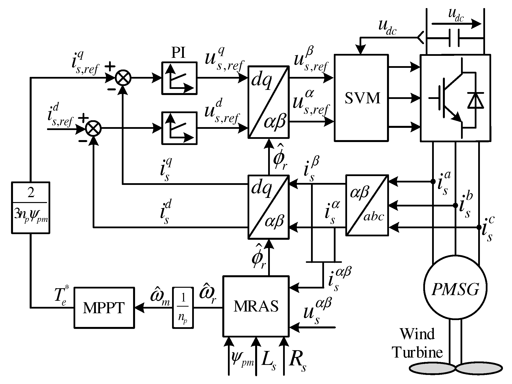
2. Modeling and Control of the SMPMSG

The variable-speed wind power generation system based on SMPMSGs is illustrated in Figure 1. As the wind speed varies with time, the generated voltage and frequency from the SMPMSG also vary. Therefore, the SMPMSG is tied to the grid by the help of power electronics. The continuous-time model of the SMPMSG in the α β -reference frame is written as [26]
u s α ( t ) = R s i s α ( t ) + d d t ψ s α ( t ) , u s β ( t ) = R s i s β ( t ) + d d t ψ s β ( t ) , }
where u s α , u s β , i s α , i s β , and ψ s α and ψ s β are the α - and β parts of the voltages, currents, and fluxes of SMPMSG stator, respectively. The stator resistance of the SMPMSG is R s . By using the rotor position ϕ r of the SMPMSG and park transformation T P ( ϕ r ) , Equation (1) can by written in the rotating reference frame as
u s d ( t ) = R s i s d ( t ) + L s d d t i s d ( t ) ω r ( t ) L s i s q ( t ) , u s q ( t ) = R s i s q ( t ) + L s d d t i s q ( t ) + ω r L s i s d ( t ) + ω r ( t ) ψ p m . }
In Equation (2), the stator inductance of the SMPMSG is L s , and the electrical angular speed of the rotor is ω r = n p ω m , where the SMPMSG has a pole pair number n p , and ω m is the rotor mechanical rotation. The permanent-magnet flux linkage is ψ p m .
The continuous-time model of the mechanical part of the SMPMSG is expressed as
d d t ω m ( t ) = 1 Θ ( T e ( t ) T m ( t ) ν ω m ( t ) ) , T e ( t ) = 3 2 n p ψ p m i s q ( t ) , }
where T e is the electro-magnetic torque, and T m is the mechanical torque. Θ is the total rotor inertia of the mechanical components, and ν is the viscous friction coefficient.
Usually, SMPMSG is controlled in the d q -reference frame, where the q-axis current regulates the electro-magnetic torque of the SMPMSG, and the d-axis current is used to fulfill the so-called maximum torque per ampere (MTPA) operation conditions (i.e., reduction of the losses in the machine to improve the conversion efficiency of the SMPMSG). In SMPMSG-based wind turbines with variable speed, the electro-magnetic torque of the SMPMSG is regulated to achieve the maximum power point tracing (MPPT) conditions. Therefore, the reference electro-magnetic torque is computed as T e ( t ) = k p ω ^ m 2 ( t ) , where k p is a positive constant and ω ^ m is the estimated mechanical speed of the rotor. Based on Equation (3), the reference q-axis current can be obtained from the reference electro-magnetic torque as i s , r e f q ( t ) = 2 3 n p ψ p m T e ( t ) . The MTPA can be recognized in the SMPMSGs by setting the d-axis reference current to zero, i.e., i s , r e f d ( t ) = 0 . Subsequently, the errors e s d ( t ) = i s , r e f d i s d ( t ) and e s d ( t ) = i s , r e f q ( t ) i s q ( t ) are fed to the PI controllers producing the actuation voltages of the SMPMSG. Finally, a modulation stage is utilized to produce the gate signals of the power converter, as illustrated in Figure 1.

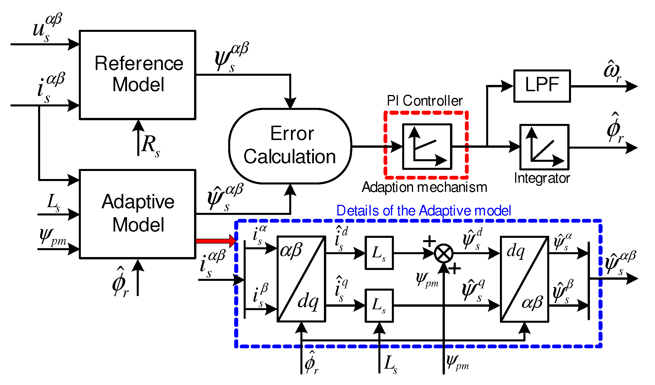
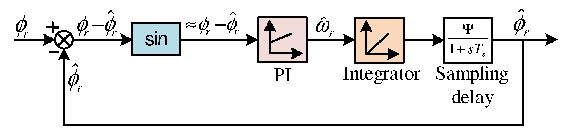
3. Classical MRAS Observer for SMPMSGs

Figure 2 depicts the structure of the classical MRAS observer for control of the SMPMSG without the use of an incremental encoder. The main components of the conventional MRAS observer are as follows [45,46]: (1) reference model, (2) adaptive model, and (3) adaptation mechanism. The reference model is not based on the rotor speed or position. Invoking Equation (1), the reference model gives the stator flux as follows
ψ s α ( t ) = 0 t ( u s α ( τ ) R s i s α ( τ ) ) d τ , ψ s β ( t ) = 0 t ( u s β ( τ ) R s i s β ( τ ) ) d τ . }
The adaptive model is based on the rotor speed and position, where the stator currents are used for observing the stator flux as illustrated in Figure 2. At first, the currents i s α and i s β are transformed to the rotating reference frame by using the observed position of the rotor ϕ ^ r . Secondly, in the d q -reference frame, the stator flux is estimated as
ψ ^ s d ( t ) = L s i ^ s d ( t ) + ψ p m   and   ψ ^ s q ( t ) = L s i ^ s q ( t ) .
Finally, the estimated flux in the d q -frame is transformed back to the α β -frame by the help of the estimated position of the rotor ϕ ^ r , as illustrated in Figure 2. The input of the adaptation mechanism is the error between the output of the reference model and adaptive model, which is expressed as
ε [ k ] = ψ ^ s α [ k ] ψ s β [ k ] ψ ^ s β [ k ] ψ s α [ k ] = | ψ ^ s α β [ k ] | | ψ s α β [ k ] | = : Ψ sin ( ϕ r [ k ] ϕ ^ r [ k ] = : Δ ϕ r [ k ] ) .
This error is handled by a fixed-gain PI controller, which updates the observed rotor position until the angle difference is zero, i.e., Δ ϕ r [ k ] : = ϕ r ϕ ^ r = 0 . In order to tune this PI controller, it is accepted to consider sin ( Δ ϕ r [ k ] ) Δ ϕ r [ k ] for small values. Accordingly, the simplified structure of the MRAS observer is illustrated in Figure 3. Considering the sampling delay and the gain Ψ , the open-loop transfer function (TF) of the traditional MRAS adaptation mechanism shown in Figure 3 can be written as
G o l ( s ) = k p i 1 + s T p i s T p i 1 1 + s T s Ψ s ,
where k p i and T p i are the PI controller parameters. Following the tuning procedure in [46], the PI controller parameters can be designed.

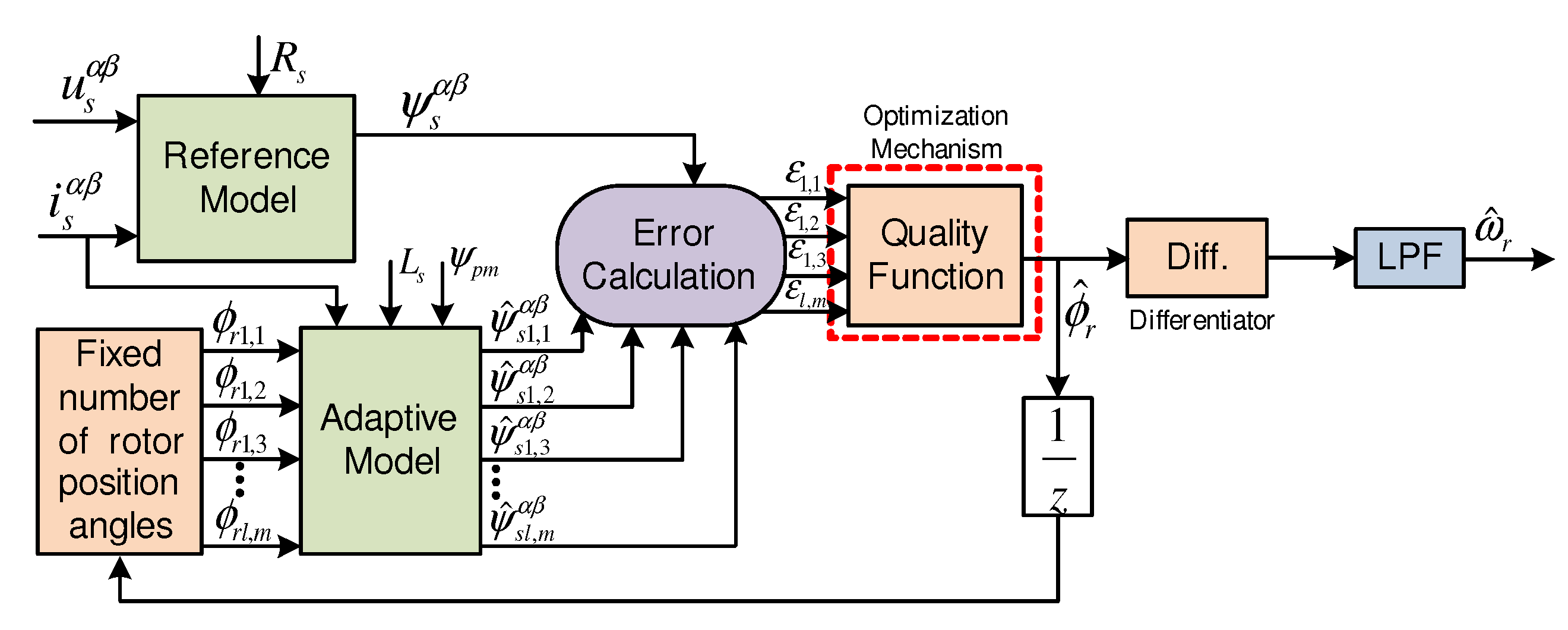
4. Proposed MRAS with Finite-Set Observer for SMPMSGs

The structure of the suggested MRAS with finite-set (MRAS-FS) observer for controlling the SMPMSG without mechanical sensors is depicted in Figure 4. The reference model of the suggested MRAS-FS is similar to the classical MRAS observer [20]. The main differences are in the adaptive model and adaption mechanism. In the adaptive model, an algorithm is developed to produce a certain number of angles for the rotor position of the SMPMSG. This idea is similar to that of the finite-control-set model predictive control (FCS-MPC), where a certain number of switching states are employed in the control algorithm. In the proposed algorithm (Algorithm 1), two loops l and m are created. Then, a displacement is formulated as
Δ ϕ l = π 4 × 2 l .
By using this displacement and
ϕ r l , m = ϕ i n , l + ( m 4 ) Δ ϕ l ,
eight angles of the rotor position can be produced at each iteration of the outer loop, which is like the eight switching vectors of the two-level voltage source converter. For example, in the first iteration of the outer loop l = 0 , then invoking Equation (8), Δ ϕ l = π 4 rad . By using m = 0 7 , eight angles are produced, which are 0, π 4 , π 2 , 3 π 4 , π , 3 π 4 , π 2 , and π 4 rad . Those eight angles are used to estimate eight values of the stator flux ψ ^ s l , m α β . Then, an optimization criteria is used instead of the fixed-gain PI regulator in the adaptation mechanism of the suggested MRAS estimator. This optimization criteria is expressed as follows:
ε l , m = ψ ^ s l , m α   ψ s β ψ ^ s l , m β   ψ s α = | ψ ^ s l , m α β [ k ] | | ψ s α β [ k ] | sin ( ϕ r [ k ] ϕ ^ r l , m [ k ] = : Δ ϕ r l , m [ k ] ) .
Algorithm 1 MRAS-FS Observer for SMPMSGs
  • Step I: Read i s α , i s β , u s α and u s β .
  • Step II: Compute ψ s α ( t ) = 0 t ( u s α ( τ ) R s i s α ( τ ) ) d τ and ψ s β ( t ) = 0 t ( u s β ( τ ) R s i s β ( τ ) ) d τ .
  • Step III:
  •   Initiate the angle ϕ i n , 0 = 0 and error ε i n =
  •   For l = 0 : 1 : 7
  •      calculate Δ ϕ l = π 4 × 2 i .
  •         For m = 0 : 1 : 7
  •            calculate ϕ l , m = ϕ i n , l + ( m 4 ) Δ ϕ l .
  •            calculate i ^ s l , m d q = T P ( ϕ l , m ) i s α β .
  •            calculate ψ ^ s d = L s i ^ s d + ψ p m and ψ ^ s q = L s i ^ s q .
  •            calculate ψ ^ s l , m α β = T P 1 ( ϕ l , m ) ψ ^ s d q .
  •            evaluate ε l , m = ψ ^ s l , m α   ψ s β ψ ^ s l , m β   ψ s α .
  •               if ε l , m < ε i n
  •                   ε i n = ε l , m
  •                   ϕ r , o p t = ϕ l , m
  •               end
  •         end
  •      set ϕ i n , l + 1 = ϕ r , o p t
  •   end
  • Step V: ϕ ^ r = ϕ r , o p t
Equation (10) represents the cross-product of the reference model output ψ s α β and adaptive model output ψ ^ s l , m α β . The value of the cost function is highly dependent on sin ( ϕ r [ k ] ϕ ^ r l , m [ k ] ) = sin ( Δ ϕ r l , m [ k ] ) . Therefore, by using Equation (10), one angle from these eight angles will be selected to be the optimal position. This angle is the one that produces the minimum error between the reference stator flux and estimated one, i.e., the minimum error between ϕ r and ϕ ^ r l , m . Furthermore, this angle will be used as the initial angle in the second iteration. Then, the algorithm will do the second iteration of the outer loop, i.e., l = 1 . Based on Equation (8), Δ ϕ l = π 8 rad . Accordingly, the accuracy, which is Δ ϕ l 2 , of the suggested algorithm is enhanced in the second iteration of the outer loop in comparison to the first iteration. After finishing all the iterations of the outer loop (i.e., l = 7 ), the accuracy of the algorithm is Δ ϕ 7 2 = 1 2 × π 4 × 2 7 = π 1024 = 0.003   rad , which is satisfactory. Note, in Algorithm 1, eight iterations of the outer loop were selected to be similar to the FCS-MPC for a two-level converter, where eight iterations are required to find the best switching action of the two-level converter.
The suggested MRAS-FS observer estimates the position of the rotor ϕ ^ r , as explained in Algorithm 1. Subsequently, this estimated angle is differentiated to estimate the speed of the rotor. However, a low-pass filter is essential to filter the estimated signal of the rotor speed, see Figure 4.

Advantages and Disadvantages of the Proposed MRAS-FS Observer

The pros of the suggested MRAS-FS observer are as follows:
  • no gains to tune, i.e., the effort and time consumed in the tuning of the fixed gain PI regulator in the conventional MRAS observer are avoided in the proposed MRAS-FS observer;
  • the dynamics of the presented MRAS-FS observer are better than the traditional dynamics due to the use of FCS-MPC principles in the design of the suggested MRAS-FS observer;
  • the suggested algorithm is not complicated and can be used in other types of machines with only small modifications.
However, the proposed MRAS-FS observer suffers from the following drawback:
  • based on Algorithm 1, 64 iterations were essential for estimating the optimal angle of the rotor position of the SMPMSG, in other words, the calculation burden of the suggested MRAS-FS observer is high. However, the current digital signal processors (DSPs) have a high calculation power, and accordingly, execution of such advanced observers can be easily realized.

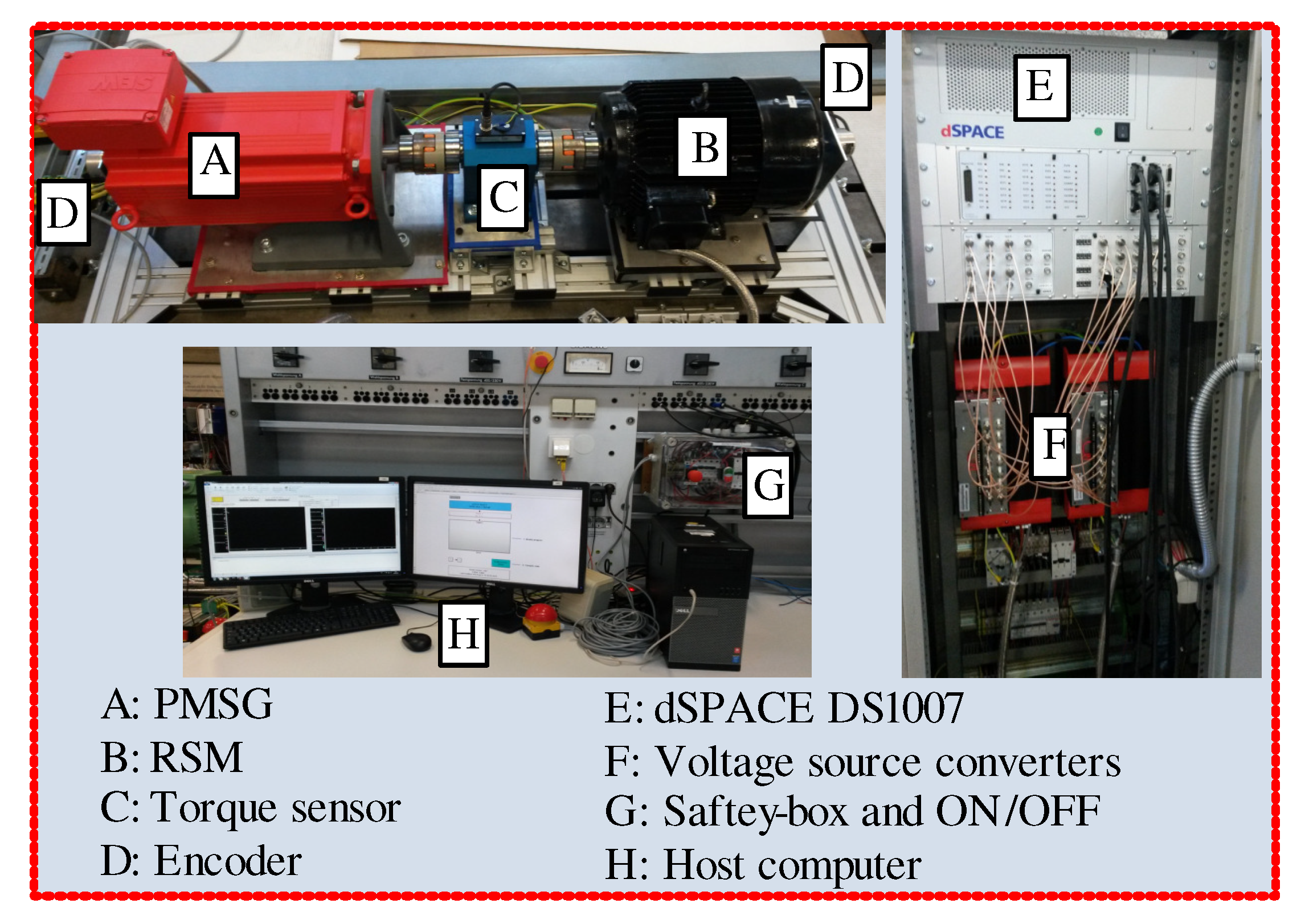
5. Description of the Laboratory Setup

The proposed MRAS-FS and traditional MRAS observers were implemented in the laboratory. The test bench was composed of a 14.5   k W SMPMSG driven by a two-level VSC, and the FOC technique was used to control it, as seen in Figure 1. A 9.5   k W reluctance synchronous machine (RSM) fed by a second two-level VSC was used to represent the dynamics and operations of the wind turbine. In real wind turbines, the mechanical rotations of the rotor ω m are regulated by the SMPMSG to fulfill the MPPT operation conditions of the wind turbine. Usually, the SMPMSG controls the speed by using a nonlinear speed controller in the form T e = k p ω m 2 , which is a very slow control scheme. Accordingly, in this work, to get quick dynamics of the speed, the RSM was controlled by a fast-speed regulation system. The SMPMSG and RSM were mechanically tied by a torque sensor as depicted in Figure 5. The control systems of the SMPMSG/RSM and MRAS observer were implemented on a dSPACE DS1007. For emulating the case of real wind turbines, 4   k Hz was selected for the switching and sampling frequency. In Figure 5 and Table 1, the constructed test bench and its parameters are given, respectively.
In order to compare the response of the MRAS observer with the real rotor position/speed, the rotor position/speed of the SMPMSG were measured by an incremental encoder. Then, a DS3002 incremental encoder board was employed to interface the measured mechanical signals with dSPACE. The voltage of the DC-link and the currents of the SMPMSG stator were measured by one voltage sensor and three current sensors, respectively. To send those signals to the dSPACE, a DS2004 analog-to-digital converter (A/D) board was utilized. In order to apply the reference voltages to the power converters, SVM was used in this work, and the switching signals were interfaced with a DS5101 pulse-width-modulation board. To practically implement the suggested MRAS-FS observer and conventional one, a low-pass filter was utilized in the reference model instead of the integrator. The PI controller proportional and integral gains of the conventional MRAS observer were selected as k p i = 667 and T p i = 9   m s , respectively. Those values give a bandwidth of 630   rad / s , which covered all speed areas of the SMPMSG under study. Consequently, the damping factor value is 2.5 , which was considered as a compromise between acceptable transient performance and sufficient bandwidth. The gain Ψ was selected to be equal to square of the permanent-magnet flux of the machine (i.e., Ψ = ψ p m 2 ) because the flux of the SMPMSG varies in a narrow range. Therefore, this assumption is valid and acceptable [46].

6. Experimental Results

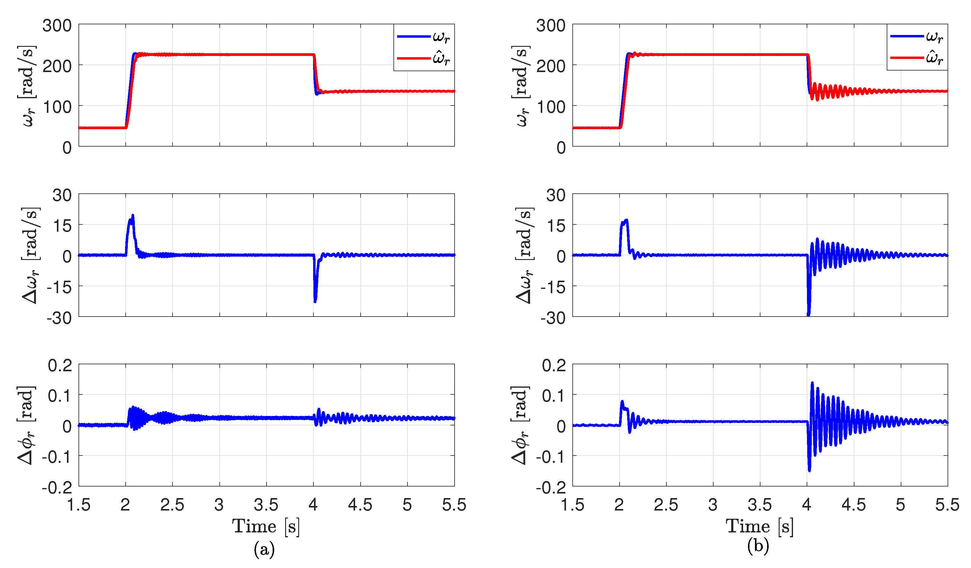
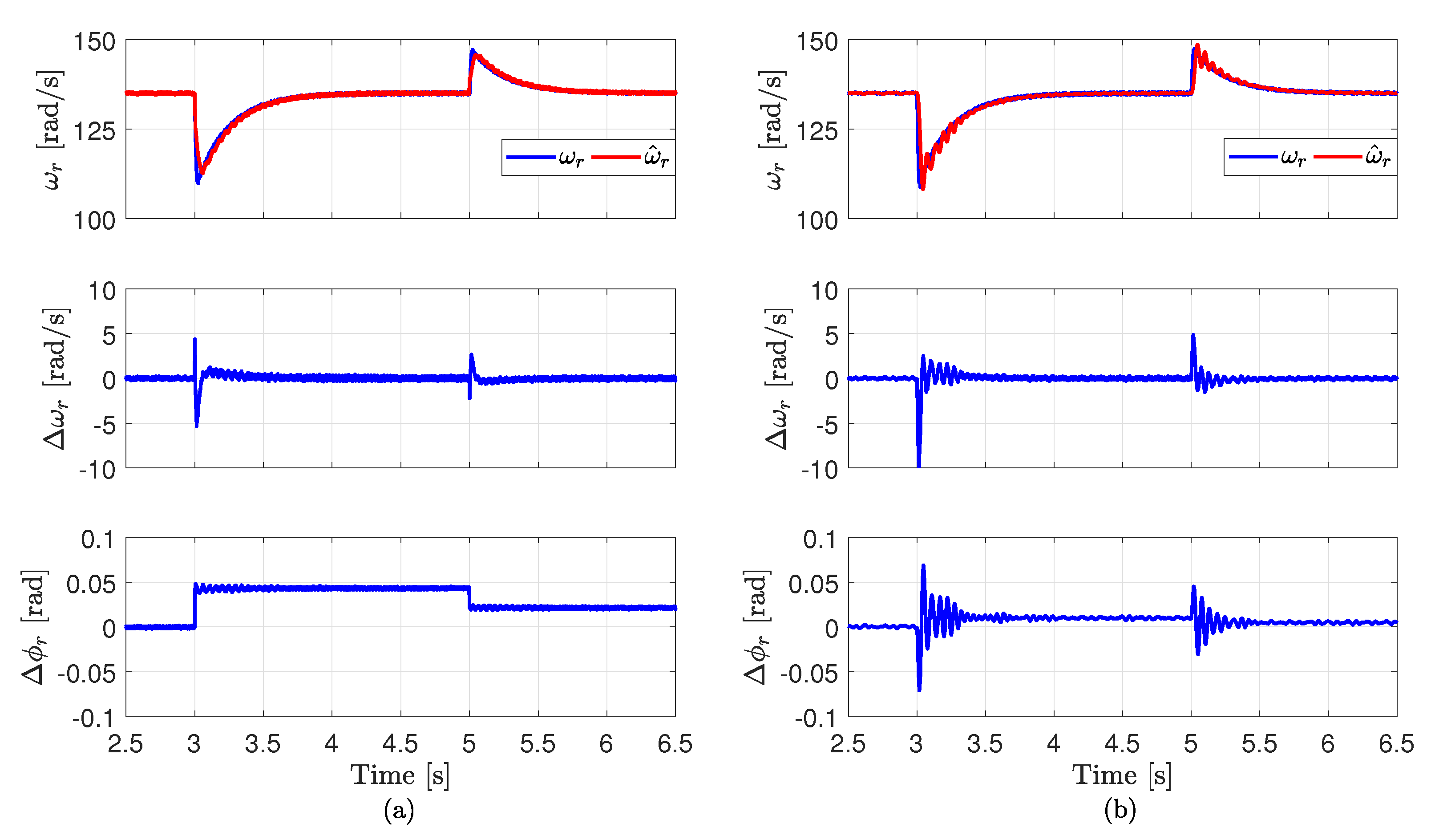
6.1. Dynamic Performance

Firstly, the dynamic performances of the presented MRAS-FS observer and the conventional one are investigated and illustrated in Figure 6 and Figure 7. In both figures, plotted waveforms from top to bottom are measured speed ω r , estimated speed ω ^ r , Δ ω r = ω r ω ^ r , and Δ ϕ r = ϕ r ϕ ^ r . The operation conditions of those two figures are detailed below.
  • In Figure 6, step changes in the reference value of the mechanical angular speed ω m , r e f from 15   rad / s to 75   rad / s and then back to 45   rad / s were applied to the RSM control system, respectively. The reference electro-magnetic torque T e is regulated to be fixed at 20   N m by the control algorithm of the SMPMSG.
  • In Figure 7, the rotor reference mechanical angular speed ω m , r e f is controlled to be constant at 45   rad / s by the RSM. Step changes in the reference electro-magnetic torque T e from 10   N m to 40   N m and then back to 25   N m were applied to the SMPMSG control scheme, respectively.
According to Figure 6 and Figure 7, the transient response of the presented MRAS-FS observer was better than that of the traditional MRAS estimator. By using the conventional MRAS estimator, high oscillations in the observed speed and position of the SMPMSG were observed during the step changes in the rotor speed and electro-magnetic torque. Those oscillations remarkably reduced or disappeared by using the proposed MRAS-FS observer. Furthermore, the proposed MRAS-FS estimator was faster than the classical one in tracking the actual rotor speed/position. Note the oscillations in the observed speed/position using the classical MRAS observer can be reduced by changing the parameters of the PI controller. However, the transient response will be very slow in this case.

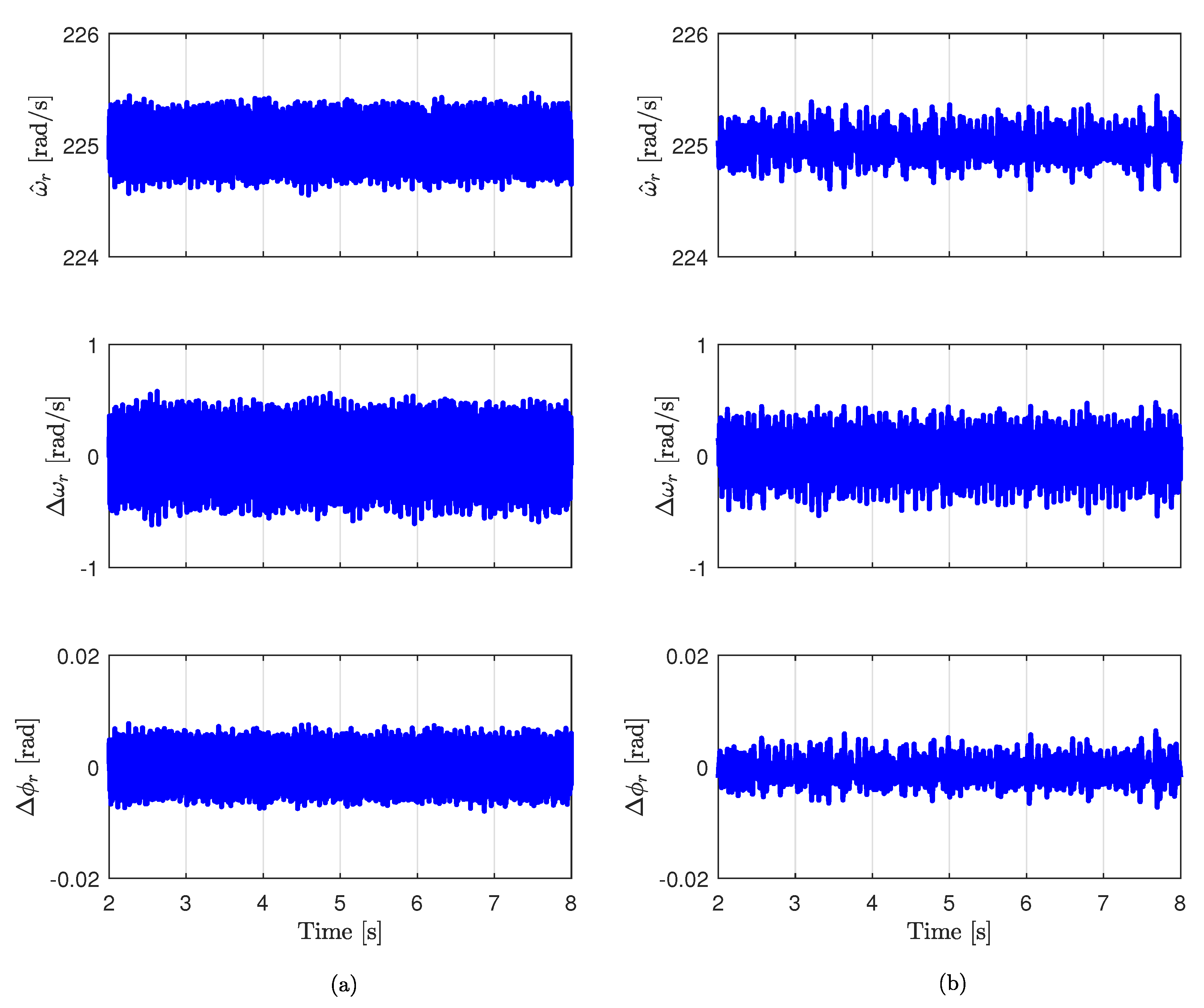
6.2. Steady-State Performance

Secondly, the steady-state performances of the presented MRAS-FS observer and the classical one are investigated and shown in Figure 8. The operation conditions at steady-state are as follows:
  • the rotor reference mechanical angular speed ω m , r e f is regulated to 75   rad / s using the RSM, and the reference electro-magnetic torque T e is regulated to be constant at 30   N m by the control algorithm of the SMPMSG.
Based on Figure 8, the ripples in the observed speed and position by the suggested MRAS-FS estimator were slightly higher than the ripples in the case of using the classical MRAS observer. This is because the suggested MRAS-FS estimator found the best position of the rotor form a limited number of angles (i.e., 64 angles), while the traditional MRAS observer estimated the rotor position from an infinite number of angles. Another reason for the slightly higher ripples is that the idea of the proposed MRAS-FS observer is taken from the FCS-MPC concept. It is well known that the FCS-MPC produces higher ripples in the output current/torque/power than those in the linear controller.
The ripples in the observed speed/position by the presented MRAS-FS observer can be reduced by increasing the number of iterations of the outer loop. However, the calculation load will significantly increase. For example, if the number of iterations of the outer loop is increased from 8 to 16 iterations, Algorithm 1 will require 16 × 8 = 128 iterations instead of 8 × 8 = 64 iterations to find the optimal rotor position. Hence, the computational burden will be doubled.

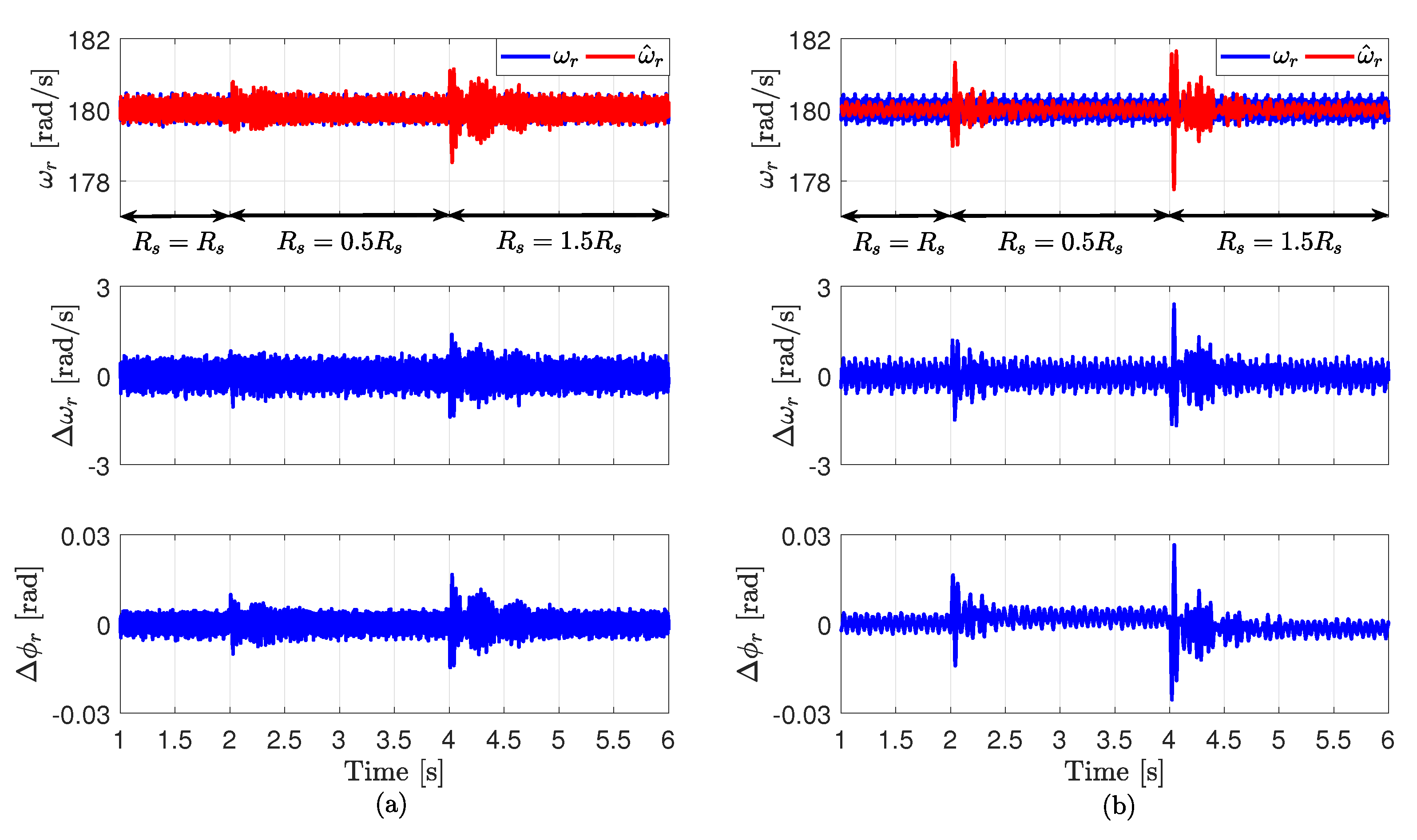
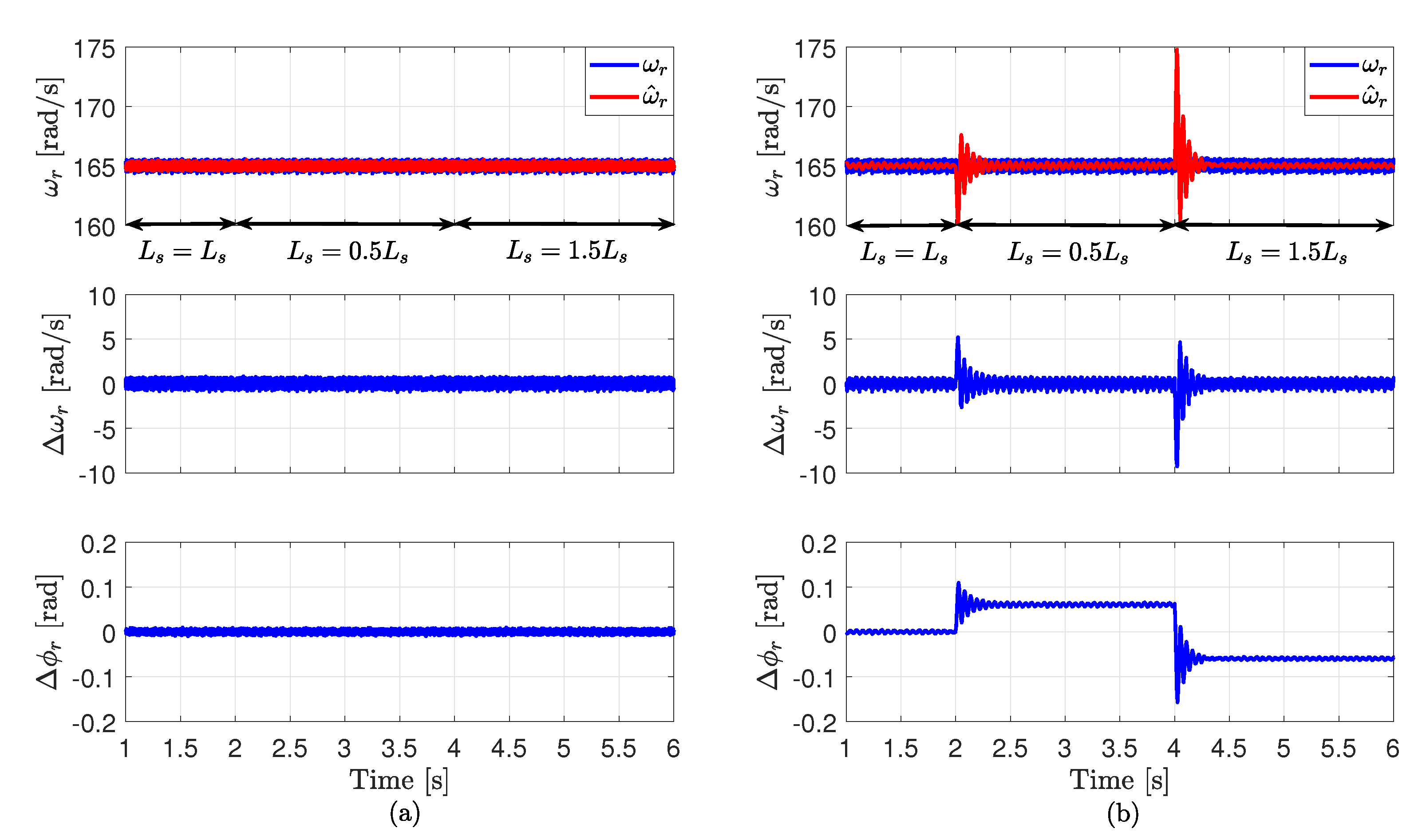
6.3. Performance at Variations of the SMPMSG Parameters

Finally, the robustness of the proposed MRAS-FS estimator and the tradational one are tested and illustrated in Figure 9 and Figure 10. The operation conditions of those two figures are as follows:
  • in Figure 9, the reference mechanical angular speed ω m , r e f of the rotor is set to 60   rad / s by the RSM control strategy, and the reference electro-magnetic torque T e is regulated to be constant at 35   N m by the control algorithm of the SMPMSG. The stator resistance R s is changed 50 % below/above its nominal value in the real-time model (i.e., within the software model);
  • in Figure 10, the reference mechanical angular speed ω m , r e f of the rotor is set to 55   rad / s by the RSM control strategy, and the reference electro-magnetic torque T e is regulated to be constant at 28   N m by the control algorithm of the SMPMSG.The stator inductance L s is changed 50 % below/above its nominal value in the real-time model (i.e., within the software model).
It is clearly seen from Figure 9 and Figure 10 that the suggested MRAS-FS observer was robust to variations of the SMPMSG parameters, while the classical MRAS estimator was highly sensitive. By using the presented MRAS-FS observer, very small oscillations appeared in the estimated speed/position of the rotor due to variations of the stator resistance R s and inductance L s , while large oscillations were seen in the response of the traditional MRAS observer.

7. Conclusions

In this paper, a model reference adaptive system with a finite-set (MRAS-FS) estimator for encoderless control of surface-mounted permanent-magnet synchronous generators (SMPMSGs) in variable-speed wind turbines has been introduced. The basic idea of the presented MRAS-FS observer is obtained from the principles of the finite-control-set model predictive control (FCS-MPC), i.e., the position of the rotor is expressed in the form of a finite set of angles. By using this limited number of angles, a certain number of values for the stator-flux of the SMPMSG can be estimated. Subsequently, an optimization criterion is formulated to select the optimal angle between those angles. This optimal angle is the one that minimizes the error between the reference stator flux and estimated one. This abolishes the necessity for a constant-gain proportional-integral in the adaptation mechanism of the MRAS estimator, i.e., no tuning work is required. The suggested MRAS-FS estimator and the conventional one were experimentally validated, and the results were analyzed and compared. The experimental results proved that the suggested MRAS-FS estimator better observed the rotor position/speed in terms of excellent transient performance. However, the steady-state performance of the presented MRAS-FS observer was slightly poorer in comparison to that of the classical one, i.e., slightly higher ripples were seen in the observed speed and position than those in the conventional MRAS estimator. Finally, unlike the traditional MRAS observer, a significant reduction in the dynamic error of the estimated rotor speed and position was seen when conducting the parameter sensitivity tests, demonstrating higher robustness against parameter variations of the SMPMSG.

Author Contributions

M.A. conceived, designed, implemented the proposed control strategy, and wrote the manuscript. C.M.H. provided the experimental platform for real-time implementation and review the manuscript. J.R. and R.K. reviewed the manuscript and were responsible for the guidance and a number of key suggestions. All authors have read and agreed to the published version of the manuscript.

Funding

This research received no external funding.

Acknowledgments

J. Rodriguez acknowledges the support of ANID through projects FB0008, ACT192013, and 1170167.

Conflicts of Interest

The authors declare no conflict of interest.

Nomenclature

u s α , u s β , u s d , u s q Stator voltagesSMPMSGSurface-mounted permanent-magnet synchronous generator
i s α , i s β , i s d , i s q Stator currentsVS-WGSVariable-speed wind generation system
ψ s α , ψ s β , ψ s d , ψ s q Stator fluxesMRAS-FSModel reference adaptive system with finite-set
R s Stator resistanceDMPCDirect-model predictive control
L s Stator inductanceDGSDistributed generation system
ψ p m PM flux-linkageRESRenewable energy system
ω r Rotor electrical speedDFIGDoubly-fed induction generator
ϕ r Rotor electrical positionBTBBack-to-back
T e Electro-magnetic torqueWECSWind energy conversion system
T m Mechanical torquePIProportional-integral

References

  1. Dasgupta, S.; Mohan, S.N.; Sahoo, S.K.; Panda, S.K. A Plug and Play Operational Approach for Implementation of an Autonomous-Micro-Grid System. IEEE Trans. Ind. Inform. 2012, 8, 615–629. [Google Scholar] [CrossRef]
  2. Kohn, W.; Zabinsky, Z.B.; Nerode, A. A Micro-Grid Distributed Intelligent Control and Management System. IEEE Trans. Smart Grid 2015, 6, 2964–2974. [Google Scholar] [CrossRef]
  3. Subramaniam, U.; Vavilapalli, S.; Padmanaban, S.; Blaabjerg, F.; Holm-Nielsen, J.B.; Almakhles, D. A Hybrid PV-Battery System for ON-Grid and OFF-Grid Applications—Controller-In-Loop Simulation Validation. Energies 2020, 13, 755. [Google Scholar] [CrossRef] [Green Version]
  4. Wind Energy in Europe in 2018, Annual Report. Available online: WindEurope.org (accessed on 7 September 2020).
  5. Datta, R.; Ranganathan, V.T. Variable-speed wind power generation using doubly fed wound rotor induction machine-a comparison with alternative schemes. IEEE Trans. Energy Convers. 2002, 17, 414–421. [Google Scholar] [CrossRef]
  6. Polinder, H.; van der Pijl, F.; de Vilder, G.; Tavner, P. Comparison of direct-drive and geared generator concepts for wind turbines. IEEE Trans. Energy Convers. 2006, 21, 725–733. [Google Scholar] [CrossRef] [Green Version]
  7. Li, H.; Chen, Z. Overview of different wind generator systems and their comparisons. IET Renew. Power Gener. 2008, 2, 123–138. [Google Scholar] [CrossRef] [Green Version]
  8. Polinder, H.; Ferreira, J.A.; Jensen, B.B.; Abrahamsen, A.B.; Atallah, K.; McMahon, R.A. Trends in Wind Turbine Generator Systems. IEEE J. Emerg. Sel. Top. Power Electron. 2013, 1, 174–185. [Google Scholar] [CrossRef]
  9. Chinchilla, M.; Arnaltes, S.; Burgos, J.C. Control of permanent magnet generators applied to variable-speed wind-energy systems connected to the grid. IEEE Trans. Energy Convers. 2006, 21, 130–135. [Google Scholar] [CrossRef] [Green Version]
  10. Li, S.; Haskew, T.A.; Swatloski, R.P.; Gathings, W. Optimal and Direct-Current Vector Control of Direct-Driven PMSG Wind Turbines. IEEE Trans. Power Electron. 2012, 27, 2325–2337. [Google Scholar] [CrossRef]
  11. Cardenas, R.; Pena, R.; Alepuz, S.; Asher, G. Overview of Control Systems for the Operation of DFIGs in Wind Energy Applications. IEEE Trans. Ind. Electron. 2013, 60, 2776–2798. [Google Scholar] [CrossRef]
  12. Zhao, Y.; Wei, C.; Zhang, Z.; Qiao, W. A Review on Position/Speed Sensorless Control for Permanent-Magnet Synchronous Machine-Based Wind Energy Conversion Systems. IEEE J. Emerg. Sel. Top. Power Electron. 2013, 1, 203–216. [Google Scholar] [CrossRef]
  13. Tong, L.; Zou, X.; Feng, S.; Chen, Y.; Kang, Y.; Huang, Q.; Huang, Y. An SRF-PLL-Based Sensorless Vector Control Using the Predictive Deadbeat Algorithm for the Direct-Driven Permanent Magnet Synchronous Generator. IEEE Trans. Power Electron. 2014, 29, 2837–2849. [Google Scholar] [CrossRef]
  14. Abdelrahem, M.; Hackl, C.; Kennel, R. Implementation and experimental investigation of a sensorless field-oriented control scheme for permanent-magnet synchronous generators. Electr. Eng. 2018, 100, 849–856. [Google Scholar] [CrossRef]
  15. Mwinyiwiwa, B.; Zhang, Y.; Shen, B.; Ooi, B. Rotor Position Phase-Locked Loop for Decoupled P-Q Control of DFIG for Wind Power Generation. IEEE Trans. Energy Convers. 2009, 24, 758–765. [Google Scholar] [CrossRef]
  16. Uddin, M.N.; Patel, N. Maximum Power Point Tracking Control of IPMSG Incorporating Loss Minimization and Speed Sensorless Schemes for Wind Energy System. IEEE Trans. Ind. Appl. 2016, 52, 1902–1912. [Google Scholar] [CrossRef]
  17. Abdelrahem, M.; Hackl, C.; Kennel, R. Model Predictive Control of Permanent Magnet Synchronous Generators in Variable-Speed Wind Turbine Systems. In Proceedings of the Power and Energy Student Summit (PESS 2016), Aachen, Germany, 19–20 January 2016. [Google Scholar]
  18. Cardenas, R.; Pena, R.; Clare, J.; Asher, G.; Proboste, J. MRAS observers for sensorless control of doubly-fed induction generators. IEEE Trans. Power Electron. 2008, 23, 1075–1084. [Google Scholar] [CrossRef]
  19. Abdelrahem, M.; Hackl, C.; Kennel, R. Encoderless Model Predictive Control of Doubly-Fed Induction Generators in Variable-Speed Wind Turbine Systems. J. Phys. Conf. Ser. 2016, 753, 1–10. [Google Scholar] [CrossRef] [Green Version]
  20. Abdelrahem, M.; Hackl, C.; Farhan, A.; Kennel, R. Finite-Set MRAS Observer for Encoderless Control of PMSGs in Wind Turbine Applications. In Proceedings of the IEEE Conference on Power Electronics and Renewable Energy (CPERE), Aswan City, Egypt, 23–25 October 2019; pp. 431–436. [Google Scholar]
  21. Abdelrahem, M.; Hackl, C.; Kennel, R. A Robust Encoderless Predictive Current Control Using Novel MRAS Observer for Surface-Mounted Permanent-Magnet Synchronous Generators. In Proceedings of the International Conference for Power Electronics, Intelligent Motion, Renewable Energy and Energy Management (PCIM), Nuremberg, Germany, 16–18 May 2017; pp. 113–120. [Google Scholar]
  22. Abdelrahem, M.; Hackl, C.; Dal, M.; Kennel, R.; Rodriguez, J. Efficient Finite-Position-Set MRAS Observer for Encoder-less Control of DFIGs. In Proceedings of the IEEE International Symposium on Predictive Control of Electrical Drives and Power Electronics (PRECEDE), Quanzhou, China, 31 May–2 June 2019; pp. 1–6. [Google Scholar]
  23. Zhang, Z.; Zhao, Y.; Qiao, W.; Qu, L. A Space-Vector-Modulated Sensorless Direct-Torque Control for Direct-Drive PMSG Wind Turbines. IEEE Trans. Ind. Appl. 2014, 50, 2331–2341. [Google Scholar] [CrossRef]
  24. Abdelrahem, M.; Catterfeld, P.; Hackl, C.; Kennel, R. A Sliding-Mode-Observer for Encoderless Direct Model Predictive Control of PMSGs. In Proceedings of the International Exhibition and Conference for Power Electronics, Intelligent Motion, Renewable Energy and Energy Management (PCIM), Nuremberg, Germany, 5–7 June 2018; pp. 1–8. [Google Scholar]
  25. Mbukani, M.W.K.; Gule, N. Comparison of high-order and second-order sliding mode observer based estimators for speed sensorless control of rotor-tied DFIG systems. IET Power Electron. 2019, 12, 3231–3241. [Google Scholar] [CrossRef]
  26. Abdelrahem, M.; Hackl, C.; Zhang, Z.; Kennel, R. Robust Predictive Control for Direct-Driven Surface-Mounted Permanent-Magnet Synchronous Generators Without Mechanical Sensors. IEEE Trans. Energy Convers. 2018, 33, 179–189. [Google Scholar] [CrossRef]
  27. Abdelrahem, M.; Hackl, C.; Kennel, R. Simplified Model Predictive Current Control without Mechanical Sensors for Variable-Speed Wind Energy Conversion Systems. Electr. Eng. 2017, 99, 367–377. [Google Scholar] [CrossRef]
  28. Abdelrahem, M.; Hackl, C.; Kennel, R. Sensorless Control of Doubly-Fed Induction Generators in Variable-Speed Wind Turbine Systems. In Proceedings of the 5th International Conference on Clean Electrical Power (ICCEP), Taormina, Italy, 16–18 June 2015; pp. 406–413. [Google Scholar]
  29. Afrasiabi, S.; Afrasiabi, M.; Rastegar, M.; Mohammadi, M.; Parang, B.; Ferdowsi, F. Ensemble Kalman Filter based Dynamic State Estimation of PMSG-based Wind Turbine. In Proceedings of the IEEE Texas Power and Energy Conference (TPEC), College Station, TX, USA, 7–8 February 2019; pp. 1–4. [Google Scholar]
  30. Azad, S.P.; Tate, J.E. Parameter estimation of doubly fed induction generator driven by wind turbine. In Proceedings of the IEEE/PES Power Systems Conference and Exposition, Phoenix, AZ, USA, 20–23 March 2011; pp. 1–8. [Google Scholar]
  31. Prajapat, G.P.; Bhui, P.; Kumar, P.; Varma, S. Estimation based Maximum Power Point Control of DFIG based Wind Turbine Systems. In Proceedings of the IEEE PES GTD Grand International Conference and Exposition Asia (GTD Asia), Bangkok, Thailand, 19–23 March 2019; pp. 673–678. [Google Scholar]
  32. Elbuluk, M.; Tong, L.; Husain, I. Neural-network-based model reference adaptive systems for high-performance motor drives and motion controls. IEEE Trans. Ind. Appl. 2002, 38, 879–886. [Google Scholar] [CrossRef]
  33. Cirrincione, M.; Pucci, M. An MRAS-based sensorless high-performance induction motor drive with a predictive adaptive model. IEEE Trans. Ind. Electron. 2005, 52, 532–551. [Google Scholar] [CrossRef]
  34. Maiti, S.; Verma, V.; Chakraborty, C.; Hori, Y. An Adaptive Speed Sensorless Induction Motor Drive with Artificial Neural Network for Stability Enhancement. IEEE Trans. Ind. Inform. 2012, 8, 757–766. [Google Scholar] [CrossRef]
  35. Gadoue, S.M.; Giaouris, D.; Finch, J.W. A new fuzzy logic based adaptation mechanism for MRAS sensorless vector control induction motor drives. In Proceedings of the IET Conference on Power Electronics, Machines and Drives (PEMD), York, UK, 2–4 April 2008; pp. 179–183. [Google Scholar]
  36. Samat, A.; Ishak, D.; Iqbal, S.; Tajudin, A. Implementation of Sugeno FIS in model reference adaptive system adaptation scheme for speed sensorless control of PMSM. In Proceedings of the IEEE International Conference on Control System, Computing and Engineering (ICCSCE), Batu Ferringhi, Malaysia, 28–30 November 2014; pp. 652–657. [Google Scholar]
  37. Gadoue, S.M.; Giaouris, D.; Finch, J.W. MRAS Sensorless Vector Control of an Induction Motor Using New Sliding-Mode and Fuzzy-Logic Adaptation Mechanisms. IEEE Trans. Energy Convers. 2010, 25, 394–402. [Google Scholar] [CrossRef]
  38. Azza, H.B.; Zaidi, N.; Jemli, M.; Boussak, M. Development and Experimental Evaluation of a Sensorless Speed Control of SPIM Using Adaptive Sliding Mode-MRAS Strategy. IEEE J. Emerg. Sel. Top. Power Electron. 2014, 2, 319–328. [Google Scholar] [CrossRef]
  39. Yan, J.; Lin, H.; Feng, Y.; Guo, X.; Huang, Y.; Zhu, Z.Q. Improved sliding mode model reference adaptive system speed observer for fuzzy control of direct-drive permanent magnet synchronous generator wind power generation system. IET Renew. Power Gener. 2013, 7, 28–35. [Google Scholar] [CrossRef]
  40. Vazquez, S.; Leon, J.; Franquelo, L.; Rodriguez, J.; Young, H.; Marquez, A.; Zanchetta, P. Model Predictive Control: A Review of Its Applications in Power Electronics. IEEE Ind. Electron. Mag. 2014, 8, 16–31. [Google Scholar] [CrossRef]
  41. Abdelrahem, M.; Hackl, C.; Kennel, R.; Rodriguez, J. Efficient Direct-Model Predictive Control with Discrete-Time Integral Action for PMSGs. IEEE Trans. Energy Convers. 2019, 34, 1063–1072. [Google Scholar] [CrossRef]
  42. Abdelrahem, M.; Kennel, R. Efficient Direct Model Predictive Control for Doubly-Fed Induction Generators. Electr. Power Compon. Syst. 2017, 45, 574–587. [Google Scholar] [CrossRef]
  43. Abdelrahem, M.; Hackl, C.; Kennel, R. Finite set model predictive control with on-line parameter estimation for active frond-end converters. Electr. Eng. 2018, 100, 1497–1507. [Google Scholar]
  44. Abdelrahem, M.; Hackl, C.; Kennel, R. Finite Position Set-Phase Locked Loop for Sensorless Control of Direct-Driven Permanent-Magnet Synchronous Generators. IEEE Trans. Power Electron. 2018, 33, 3097–3105. [Google Scholar]
  45. Schauder, C. Adaptive speed identification for vector control of induction motors without rotational transducers. IEEE Trans. Ind. Appl. 1992, 28, 1054–1061. [Google Scholar]
  46. Andreescu, G.D. Position and Speed Sensorless Control of PMSM Drives Based on Adaptive Observer. In Proceedings of the 8th European Conference on Power Electronics and Applications (EPE ’99), Lausanne, Switzerland, 7–9 September 1999; pp. 1–10. [Google Scholar]
Figure 1. Encoderless field-oriented control for surface-mounted permanent-magnet synchronous generators (SMPMSGs) in variable-speed wind turbine systems.
Energies 13 04844 g001
Figure 2. Structure of the traditional model reference adaptive system (MRAS) observer for SMPMSGs.
Energies 13 04844 g002
Figure 3. Simplified structure of the traditional MRAS observer.
Energies 13 04844 g003
Figure 4. Structure of the proposed MRAS-FS observer for control of SMPMSGs without mechanical encoders.
Energies 13 04844 g004
Figure 5. Laboratory setup utilized to validate the presented MRAS-FS observer.
Energies 13 04844 g005
Figure 6. Experimental results at step changes in the mechanical speed of the rotor ω r of the SMPMSG: (a) MRAS-FS and (b) conventional MRAS.
Energies 13 04844 g006
Figure 7. Experimental results for step changes in the electro-magnetic torque T e : (a) MRAS-FS and (b) conventional MRAS.
Energies 13 04844 g007
Figure 8. Experimental response at steady-state: (a) MRAS-FS estimator, and (b) conventional MRAS.
Energies 13 04844 g008
Figure 9. Experimental performance under step changes in the stator resistance R s of the SMPMSG: (a) MRAS-FS observer, and (b) classical MRAS.
Energies 13 04844 g009
Figure 10. Experimental performance under step changes in the stator inductance L s of the SMPMSG: (a) MRAS-FS observer, and (b) classical MRAS.
Energies 13 04844 g010
Table 1. SMPMSG parameters.
NameSymbolValue
Nominal power p r a t e d 14.5   k W
Nominal line-line voltage of the SMPMSG stator u s , r a t e d 400   V
Rated voltage of the DC-link u d c 560   V
Nominal mechanical angular speed of the rotor ω m , r a t e d 209   rad / s
Resistance of the SMPMSG stator R s 0.15   Ω
Inductance of the SMPMSG stator L s 3.4   m H
Permanent-magnet flux linkage ψ p m 0.3753   Wb
Number of pole pairs n p 3

