Abstract
Preventing the medium voltage (MV) transformer fault by protecting transformers against indirect lightning strikes plays a crucial role in enhancing the continuous service to electricity consumers. Surge arresters, if selected properly, are efficient devices in providing adequate protection for MV transformers against transient overvoltage impulses while preventing unwanted service interruptions. However, compared to other protective devices such as the spark gap, their prices are relatively high. The higher the surge arrester rating and energy absorption capacity are, the higher the prices go. This paper proposes an inductor-based filter to limit the energy pushed into the surge arrester, and consequently to prevent any unwanted failure. An energy-controlled switch is proposed to simulate the fault of the surge arrester. Surge arresters with different ratings, e.g., 12 kV, 18 kV, 24 kV, 30 kV, 36 kV, and 42 kV with two different classes of energy, namely, type a and type b, are tested under different indirect lightning impulses such as 100 kV, 125 kV, 150 kV, 175 kV, 200 kV, 250 kV, 300 kV, and 500 kV. Furthermore, these surge arresters are equipped with different filter sizes of 100 , 250 , 500 , and 1 . Results prove that equipping a surge arrester with a proper filter size enhances the performance of the surge arrester significantly such that a high rating and somewhat expensive surge arrester can be replaced by a low rating and cheap surge arrester while providing similar or even better protective performance for MV transformers. Therefore, such configurations not only enhance the protective capability of surge arrester, but also reduce the planning and operating costs of MV networks.
1. Introduction
Indirect lightning phenomena are more common than direct lightning and are considered as one of the primary sources of failures and damages in the medium voltage (MV) equipment by causing stress on their insulation system [1,2]. The MV transformers, among all the equipment, are more expensive, and thus providing adequate protection for them is of high importance. Proper protection of transformers not only enhances the system reliability as well as social welfare, but also, by controlling the transient overvoltage stress, prevents/defers extra expenses imposed by transformer failure or severe damages [3].
In practice, typically spark gaps are used to protect the transformers in MV networks against lightning impulses [4]. Although spark gaps are rather cheap protective devices, their operation yields a service interruption due to voltage chop and such voltage chopping imposes steep voltage stress across the transformer terminal [5,6]. Besides, transients may also occur due to the energization of the transformer [7] after the follow current interruption due to spark gap operation. On the other hand, surge arresters, by their charming nonlinear behavior as well as surge energy capabilities, can provide adequate protection against lightning impulses while preventing any unwanted service interruption [8]. However, utilizing a surge arrester as the protective device may not always protect the MV transformers against lightning [9,10]. A report by the Cigre Study Committee A2.37 on the failure rate of MV transformers lists the failure rate of surge arrester-protected transformers due to lightning as ~3% [11].
In the literature, there exist several works that either only conventional surge arresters are considered to protect MV transformers against lightning, or some external or internal modifications are made aiming at enhancing the protective performance of surge arresters. In internal modifications, the microstructure and electrical properties of surge arresters are optimized to withstand different overvoltage conditions [12,13,14,15]. In external modifications, which is the focus of our work, more often than not, only other protective devices are combined with surge arresters, or different sides of the transformer are chosen for installing the surge arresters aiming at enhancing the protection outcome [6]. When a conventional surge arrester is used for protecting MV transformers, several characteristics should be taken into account to prevent unwanted failures or returning to normal operating condition after absorbing surge energy [16]. Among all, the thermal energy absorption limit plays a crucial role in guaranteeing the healthy operation of the surge arrester while absorbing surge energy. Moreover, the authors of [17] showed that if the surge arrester is installed closer to the transformer, the overvoltage stress transferred to the LV side of transformer tends to increase; although, to keep the overvoltage stress as low as possible on the MV side of the transformer, the surge arrester needs to be installed as close as possible to the transformer. The authors of [18] provided adequate information on selecting the surge arresters for residential areas. In a distribution network, the placement of surge arresters is a crucial challenge [19], where installing too many surge arresters increases the probability of surge arrester failure, and consequently unwanted outages may occur [20]. One approach is to decrease the number of surge arresters in the network [20], while strengthening the surge arrester and enhancing its performance against lightning overvoltages can be another alternative. In [6], the authors concluded that instead of using a surge arrester with a rather high rating, a series connection of a spark gap and a surge arrester might provide a similar protection level, and a lower rating surge arrester can be considered. However, in this work, the thermal energy absorption limit was not thoroughly investigated. Several other combinations of the spark gap and surge arresters have been studied to enhance the protection quality. For example, in [21], the spark gaps were installed at the MV terminals of the transformer and the LV terminals were protected by low rating surge arrester, while in [22] surge arresters and spark gaps were installed at the MV and LV terminals of the transformer, respectively. In [23], experts advised installing surge arresters at both the MV and LV terminals, which will impose additional costs to the system operator. The authors of [24] proposed a novel idea in which the surge arrester wa replaced by an inexpensive LC filter, and it was shown that even by removing all surge arresters in power system, the lightning overvoltages were kept below the BIL.
According to the literature review above, and to the best of our knowledge, (a) there is a gap on modeling the failure of surge arrester due to absorbing excess energy; (b) no work, so far, considered a filter for controlling the energy pushed into the surge arrester; and (c) there is a gap in investigating the impact of series-connected spark gap on the energy absorbed by surge arresters.
Therefore, the primary contributions of this work are fourfold:
- Proposing a filtered surge arrester to mitigate lightning overvoltages by limiting the energy pushed into the surge arrester.
- Proposing an energy-controlled switch to model the fault behavior of surge arrester due to absorbing excess energy.
- Investigating the impact of the proposed filter on enhancing the protective performance of the surge arrester for protecting MV transformers against indirect lightning phenomena.
- Investigating the impact of the joint spark gap and proposed surge arrester on protecting an MV transformer against indirect lightning phenomena.
2. Simulation Setup
This section provides detailed information on the simulation set-up for testing the proposed filtered surge arrester. The components to be modeled in EMTP-RV are indirect lightning impulse, transformer, spark gap, surge arrester, and energy-controlled switch.
2.1. Indirect Lightning
In this paper, the double exponential Equation (1) is used to generate standard indirect lightning, where stands for the front-time and represents the time-to-half value. It is worth mentioning that this standard waveform is subject to a simplification since this representation assumes that the lightning current rises linearly until reaching the peak and neglects the influence of channel-base current [25,26]. In EMTP-RV, there exist a voltage surge device that takes advantage of a double exponential function to generate lightning impulses, see Figure 1.
where is the maximum voltage of the source, and and are the coefficients to adjust the front time (e.g., ) and time-to-half value (e.g., ), respectively [27]. It is worth mentioning that, in EMTP-RV, this device has two options for start time and stop time to have more control over generating the surge impulses. However, generating indirect lightning impulse in software by using a double exponential function is not always an easy task. Determining the sensitive parameters of and for the double exponential function (1) is a challenging issue. In [28], an innovative approach was used to define the parameters of and , while for the sake of facilitating the parameter adjustments, an A factor was also used. Then, all the parameters A, , and were obtained via trial and error method, and the results show some violations compared to the standard lightnng impulse. Therefore, adjusting these sensitive parameters requires utilizing some optimization model. In this work, the optimization model developed by Pourakbari-Kasmaei et al. in [29] is modified as (2)–(6).
where is the peak value of the lightning impulse, is the frontier time, is the time to half value, and is the half value. In this paper, the A factor is melted into the such that , and more often than not, to determine the desired voltage, is set a bit higher than , i.e., A is greater than or equal to 1.
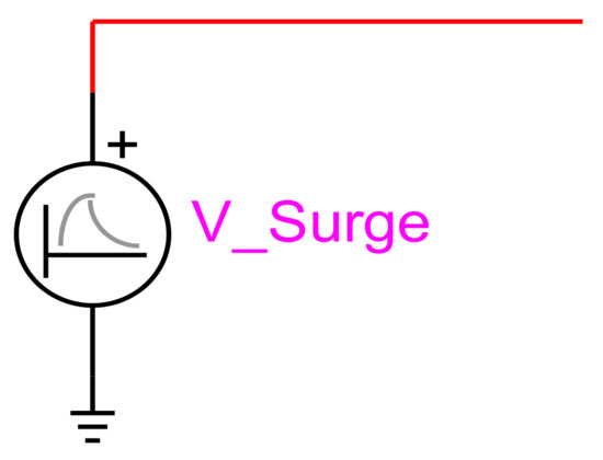
Figure 1.
Voltage surge device to generate indirect lightning impulses.
To the best of our knowledge and according to practical experiences, to generate an indirect lightning impulse, parameters and take negative values. Therefore, maximizing the summation of these negative values guarantee to find the smallest values, which is extremely beneficial in enhancing the computational efficiency in transient studies via the EMTP-RV software [30]. It is noteworthy to mention that in order to support open access, the developed GAMS code used to obtain the parameters of the double exponential function for simulating an indirect standard 100 kV lightning impulse is available in [31].
2.2. Transformer
In this work, a Delta-Star () 22/0.4 kV transformer is modeled in the EMTP-RV environment, according to Cigre Guidelines [32]. The transformer comprises three basic building blocks as Figure 2 to present the 3-phase transformer model, see Figure 3. In high voltage studies, capacities on the MV side, LV side, and between MV and LV sides play a crucial role in obtaining more realistic results. The capacitor sizes are derived from the work in [33].
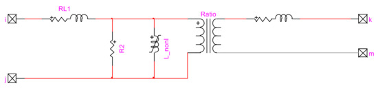
Figure 2.
Basic building block for each phase of the transformer, EMTP-RV model.
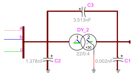
Figure 3.
-connection model of the transformer with measured capacitances.
2.3. Spark Gap
A spark gap is the most commonly used device used to protect the transformers by limiting the overvoltage amplitude (chopping the voltage at a certain level). The spark gap is triggered when the overvoltage across its terminals exceeds the critical flashover voltage [34]. In most works, for the sake of simplicity, to model the behavior of the spark gap, a voltage-controlled switch is used [6,21], which cannot take into account the nature of different surge impulses. In this paper, to avoid such shortcomings and to simulate the behavior of the spark gap as close as the practical situation, the disruptive effect (DE) method (7) is used [35]. In this formulation, the flashover occurs when the integral part becomes greater than or equal to D. The integral function enables calculating the moment that the spark gap is ready to be triggered regardless of the waveform.
where k and D are an empirical constant and the disruptive effect constant (kV µs), respectively; is the onset voltage of primary ionization (kV); and is the time corresponding to this primary ionization.
2.4. Surge Arrester
This subsection provides adequate information on the surge arrester and its fault model.
2.4.1. Frequency-Dependent Model
In order to simulate the behavior of a surge arrester, a frequency-dependent model of a metal oxide surge arrester, known as metal oxide varistor (MOV) surge arresters, is used. The modeling is done based on the guidelines provided by IEEE Working Group 3.4.11 [36]. The most commonly used frequency-dependent model is an RLC circuit with two nonlinear resistances Ao and A1 separated by an R-L filter, see Figure 4. The voltage-current (V-I) characteristics of the nonlinear resistances are derived from the work in [36], and the functionality of each type of surge arrester has been verified by performing a simulation-based test under a 10 kA current impulse (8/20 μs) and compared with the practical information obtained from [37].
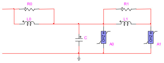
Figure 4.
Frequency-dependent metal oxide surge arrester.
Practically, a transformer is under risk if the voltage at the MV side of the transformer is above 125 kV [38,39]. Therefore, in this paper, to have a safe margin from the risky overvoltage level, the goal is to keep the overvoltage amplitude below 100 kV, and to this end, only surge arresters with residual voltage below 100 kV are studied. Detailed information of the understudy surge arresters is presented in Table 1 [37], where “a” and “b” stand for the normal and high energy discharge capabilities of surge arresters, respectively.

Table 1.
Surge arresters’ characteristics [37].
Needless to say, the lower rating surge arresters and the normal energy class, due to lower costs, are of more interest to the system operators [6]. The nominal discharge current for the arresters is 10 kA, while the rated short circuit current is 50 kA (the maximum current flowing for a duration of 200 ms), and the peak value is ~125 kA, i.e., the currents for which the surge arrester withstand without sending the fractured part outside the circle with radius H (height of surge arrester) [37,40,41].
It is noteworthy to mention that to select a suitable surge arrester, several criteria should be taken into accounts, such as continuous operating voltage and rated voltage, nominal discharge current, protective level, energy class, and protective zone. More often than not, the protection capabilities of a surge arrester are evaluated according to its residual voltage while the nominal discharge current is flowing through it. A practical method to calculate a suitable residual voltage of the surge arrester is dividing the basic insulation level of the equipment to be protected by a factor of 1.4 as in (8) [37].
where is the protective level of the surge arrester at a nominal current of 10 kA, 8/20 , and BIL is the basic insulation level of the equipment, i.e., an MV transformer in this work with a 150 kV BIL.
2.4.2. Surge Arrester Fault Model
More often than not, a failure in the arrester causes a complete short circuit. In most situations, dielectric breakdown is the source of such failure. Lightning surges, among others, are one of the most common circumstances against which an arrester faces an overvoltage beyond the withstand voltage and the dielectric breakdown results [42]. If the input energy to a surge arrester exceeds the thermal energy absorption limit, the arrester is pushed into a thermal runaway condition [43], and consequently the MOV blocks eventually become so conductive that these blocks cannot support even the maximum continuous operating voltage. More information on thermal runaway can be found in [44]. That is, the surge arrester will be completely short-circuited [42]. Therefore, to obtain more practical results, the fault behavior of surge arresters needs to be modeled. In this work, an energy-controlled switch is developed to simulate the behavior of surge arresters under fault conditions. The switch is closed once the absorbed energy of the surge arrester exceeds the thermal energy absorption limit, as in (9).
where and are the absorbed energy by surge arrester and its thermal energy absorption limit, respectively; stands for instantaneous voltage across the surge arrester; and represents the current flow through the surge arrester. The integral part of this equation stands for the area below the multiplication of the instantaneous voltage and current of the surge arrester, which is equal to energy. It is worth mentioning that the energy absorption capability of the surge arrester is not a constant value and highly depends on the microstructure (non-)uniformity and the stress conditions of the varistor [45]. However, more often than not, for the sake of simplicity, the factories provide a constant value, as presented in Table 1.
Figure 5 presents the proposed fault model of the surge arrester. An energy-controlled switch in the EMTP-RV environment is used to model the behavior of the surge arrester when excess energy is pushed into it. In this figure, for didactic purposes, alongside, below, or on top of each block, the measured signals and the utilized functions to calculate the absorbed energy of surge arrester have been presented.
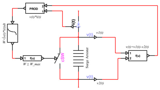
Figure 5.
Modeling surge arrester fault via an energy-controlled switch.
2.5. Arrangement of Lightning Protection Devices
Figure 6 presents the arrangements of lightning protection devices for MV transformers. In Figure 6a, the transformer is protected by a sole surge arrester, while in Figure 6b, an inductor is used as the filter. The joint surge arrester and spark gap are presented in Figure 6c, and Figure 6d shows the filtered surge arrester and spark gap.
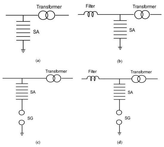
Figure 6.
Lightning protection arrangement for MV transformers with (a) surge arrester, (b) filtered surge arrester, (c) joint surge arrester and spark gap, and (d) filtered surge arrester and spark gap.
Figure 7 resents the configuration of the transformer protected by surge arrester, spark gap, or a series connection of both devices in the EMTP-RV software. In this configuration, for the sake of simplicity, only the indirect lightning impulses are applied on one terminal of the MV transformer, namely, terminal a, while all the measurements are carried out on the connection point of the protective devices, see point (a) in Figure 7. All the arrangements presented in Figure 6 can be made in the EMTP-RV model in Figure 7. Wires (b) and (c) are used for adding/eliminating the surge arrester and spark gap by disconnecting/connecting the two oval points of these wires, respectively. In this figure, the R in R_L stands for the internal resistance of the L filter. In this paper, for the sake of simplicity, an 1 internal resistance has been considered for all inductors. In case that there is no filter, a 1 resistor will be considered to take into account the resistance of the connecting wire between the lightning impulse and the transformer. The switch across the surge arrester is an energy-controlled switch, modeled in Section 2.4.2. Rd is the damping resistor, and in this paper, it is set to 200 .
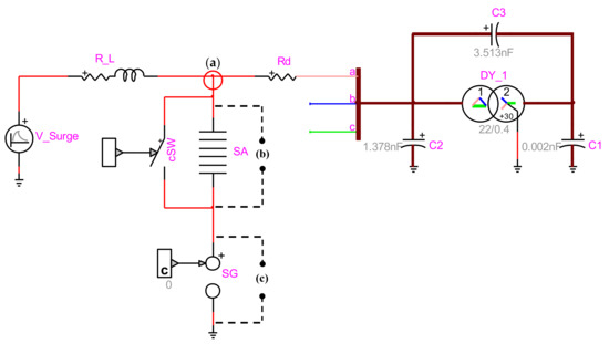
Figure 7.
Series connection of surge arrester (SA) and spark gap (SG); (a) measurement point for overvoltage stress, (b) adding/eliminating the SA by disconnecting/connecting this wire, and (c) adding/eliminating the SG by disconnecting/connecting this wire.
3. Model Validation, Case Studies, and Simulation Results
In this section, first we validate the functionality of the proposed energy-controlled switch, which is used to model the surge arrester’s fault condition due to absorbing energy higher than the thermal energy absorption limit. Then, several case studies are performed to see the potential of filtered surge arrester compared with the conventional surge arrester and series connection of surge arrester and spark gap. However, before validating the model and performing profound analyses, the lightning impulses need to be generated. Table 2 presents the optimal parameters of the double exponential model (1), obtained by solving (2)–(6). Most indirect lightning strikes have an overvoltage amplitude of less than 300 kV [46]. Therefore, in this work, we focus more on the overvoltages below 300 kV, though, a very high indirect overvoltage (500 kV) has also been introduced just to investigate the performance of protective devices under such high overvoltage stress. Table 2 can be used as a quick source for interested readers to generate the desired indirect lightning impulses.
Table 2.
Optimal parameters of the double exponential model to generate indirect lightning impulses.
3.1. Model Validation Validating the Surge Arrester Fault Model and the Spark Gap
This subsection provides adequate information and comparisons to validate the models of protective devices.
3.1.1. Validating the Surge Arrester Fault Model
In order to validate the proposed surge arrester fault model, the surge arrester with the highest thermal energy absorption limit, i.e., SA-42b (see Table 1), which can resist better than the lower rating and energy class-a surge arresters against different lightning overvoltage levels, is used.
Figure 8a–h demonstrates the measured voltage at the MV side of the transformer (see point (a) in Figure 7), the absorbed energy by surge arrester, and the current flow through the surge arrester upon the ignition under different indirect lightning impulses. The time period in which the surge arrester is active can be verified by the current curve, i.e., whenever there is a current flow, the surge arrester is active, otherwise, it is an open circuit. As can be seen in Figure 8a, by applying a 100 kV lightning impulse, the surge arrester is active only for a short period of time while the current peak is about 5 kA. The energy absorbed by the surge arrester under this lightning impulse is ~4 kJ, which is well below its thermal energy absorption limit, 294 kJ; therefore, the surge arrester works properly, and no short circuit occurs. That is, under normal conditions, the switch remains open. Similarly, in Figure 8 b–e, the absorbed energy is below 294 kJ, and the surge arrester can effectively protect the transformer while not interrupting the service to the electricity consumers. In this figure, as the applied lightning impulse increases, the amplitude of current flow through the surge arrester increases, and consequently, the surge arrester absorbs a higher amount of energy. For example, in Figure 8b, compared with Figure 8a, increasing the lightning impulse by ~25 kV results in an ~12.5 kA increase in the current flow through the surge arrester while its absorbed energy faces a 21 kJ increase. Another observation from Figure 8a–e is that although the amplitude of the lightning impulse is increased by a step of 25 kV, the increases of the current and absorbed energy do not follow a linear pattern. This is mainly due to the nonlinear characteristic of metal oxide surge arresters [47]. As an instance, under the 200 kV lightning impulse, in Figure 8e, compared with the 175 kV lightning impulse, in Figure 8d, by increasing 12.5% in the lightning impulse, the absorbed energy is increased by ~56.8% (from 143.8 kJ to 228.31 kJ), while the operating duration and the peak current flow are increased by about 10 and 19.38 kA, respectively. The appropriate operation of the surge arrester continues until its absorbed energy exceeds the thermal absorption limit, as can be seen in Figure 8f–h where the surge arrester pushed into a failure. As can be seen from these figures, under such conditions a fault occurs, and the current flow through the surge arrester shows a considerable jump due to the proper functionality of the proposed energy-controlled switch under the faulty situation. When the surge arrester is short-circuited, the voltage at the transformer terminal reaches to zero. That is, continuous service to electricity consumers will be interrupted.
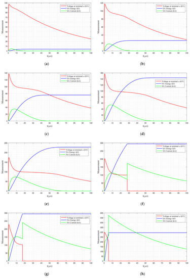
Figure 8.
Performance of surge arrester SA-42b under lightning impulse voltage (a) 100 kV, (b) 125 kV, (c) 150, (d) 175 kV, (e) 200 kV, (f) 250 kV, (g) 300 kV, and (h) 500 kV.
Moreover, Figure 8f–h shows that the higher the lightning impulse is the faster the thermal absorption limit is reached and the surge arrester fault occurs such that under the 500 kV lightning impulse, Figure 8h, the surge arrester cannot even withstand to decrease the overvoltage amplitude below the risky overvoltage level, 125 kV [38,39].
Comparing the energy levels of the surge arrester under normal operating conditions, in Figure 8a–e, and the short circuit conditions, in Figure 8f–h, it can be deduced that the energy-controlled switch is working properly. That is, the proposed fault model (see Section 2.4.2) is validated. Please note that, besides a fault occurring due to pushing higher energy into the surge arrester, the current flow through it may cause failure as well. In this paper, for the sake of simplicity, after the failure, the impedance has been set to zero, while in practice, even when the varistor failure occurs, there is a non-zero impedance. Besides, in this work, the ground resistance of the transformer and the conductive coupling of the surge arrester have not been considered.
3.1.2. Validating the Spark Gap
Although more often than not some approximation methods are used to adjust the sensitive parameters of the DE method (7), i.e., k, , and D, the best way to properly adjust these parameters is to have some experimental data. In this work, an 8 cm sphere–sphere spark gap, presented in Figure 9, is used [33].
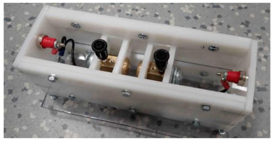
Figure 9.
Adjustable sphere–sphere spark gap [33].
The validation is done by applying a nonstandard 125 kV overvoltage impulse on the transformer terminal at the presence of a spark gap. In this work, first, the method proposed by the Cigre Working Group 01 [48] is used to estimate the (), and according to the work in [35], if is large, then is considered to be lower than or equal to 1, then a trial and error method is used to find the best values for k and D that yields to a better agreement with the laboratory results. By using this approach, the following parameter have been obtained; kV, , and 0.01. Figure 10a depicts the applied laboratory impulse (the green curve) and the simulated impulse in EMTP-RV (the blue curve). Figure 10b compares the performances of the spark gap under the laboratory test and via the DE method. As can be seen from this figure, there is a good agreement between the laboratory test and the results obtained in EMTP-RV software. Interested readers may refer to the work in [49] for obtaining a complete report on the laboratory setup, supporting figures, as well as a wide range of experimental results at the presence of spark gap, while more information regarding the applied impulses and the validation of the spark gap can be found in [33,50].
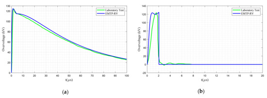
Figure 10.
(a) Applied nonstandard 125 kV lightning impulse. (b) Measured overvoltage stress at the presence of spark gap [33].
3.2. Case Studies
To perform in-depth analyses on the protective performances of surge arresters against overvoltage surges, several case studies are conducted. The primary goals of the following case studies are (a) to investigate the degree of effectiveness of considering surge arrester in protecting the MV transformers against indirect lightning phenomena; (b) showing the pros and cons of considering a series connection of surge arrester and spark gap; and (c) investigating the effectiveness of considering an inductor-based filter, as the main contribution of this work, on enhancing the functionality of surge arrester in preventing unwanted service interruption while protecting the MV transformers against indirect lightning surges. In this work, and in order to achieve the aforementioned goals, the following case studies are conducted.
- Case 1
- Transformer protected by surge arrester. The main goal of this case is to reveal the protection capability of different surge arresters in protecting MV transformers against various indirect lightning overvoltages.
- Case 2
- Transformer protected by a series connection of surge arrester and spark gap. This case is used to investigate the impact of the combined protective devices on the overvoltage stress and protection of MV transformers against indirect lightning.
- Case 3
- Transformer protected by filtered surge arrester. The primary goal of this case is to investigate the impact of an inductor-based filter on the performance and operating margin of surge arresters.
- Case 4
- Transformer protected by a series connection of filtered surge arrester and spark gap. This case investigates the role of an inductor-based filter on the protective performance of a combined surge arrester and spark gap devices, presented in Case 2.
3.3. Simulation Results and Discussions
3.3.1. Case 1. Transformer Protected by Surge Arrester
This case investigates the protection capability of various surge arresters, listed in Table 1, in protecting MV transformers against different indirect lightning overvoltages, presented in Table 2. In this work, the protection capability is defined as the overvoltage level under which the surge arrester does not experience any failure. To perform the simulation setup, the two oval points of wire (b) in Figure 7 are disconnected to keep the surge arrester in the circuit, while the two oval points of wire (c) are connected to eliminate the spark gap.
As this case focuses on finding the proper functionality margin of the surge arresters, then, for the sake of unambiguity, only the performance of the surge arrester related to the lightning impulse with the lowest overvoltage amplitude against which a fault, i.e., short circuit, occurs is reported. In other words, for lightning impulses with overvoltage amplitude lower than this fault-causing lightning impulse, the surge arrester protects the MV transformer properly. Figure 11, Figure 12, Figure 13, Figure 14 and Figure 15 present the failure occurrence of different surge arresters with two energy classes.
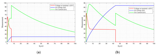
Figure 11.
Failure of (a) SA-12a under 100 kV lightning impulse and (b) SA-12b under 125 kV lightning impulse.
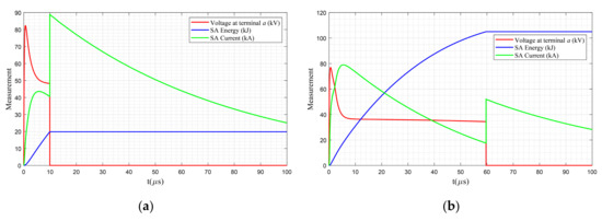
Figure 12.
Failure of (a) SA-18a under 100 kV lightning impulse and (b) SA-18b under 125 kV lightning impulse.
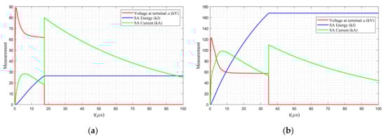
Figure 13.
Failure of (a) SA-24a under 100 kV lightning impulse and (b) SA-24b under 175 kV lightning impulse.
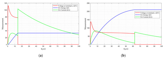
Figure 14.
Failure of (a) SA-30a under 125 kV lightning impulse and (b) SA-30b under 175 kV lightning impulse.
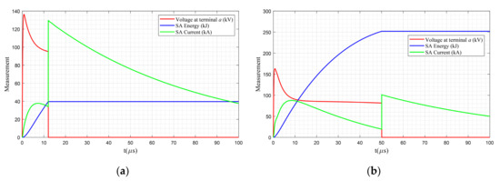
Figure 15.
Failure of 36 kV surge arrester (a) for SA-36a under 150 kV lightning impulse and (b) for SA-36b under 200 kV lightning impulse.
In Figure 11a, the surge arrester SA-12a is used, which has a lower thermal absorption capacity than the SA-12b; in Figure 11b, a 100 kV lightning impulse results in a fault within ~6.1 , while such failure for the SA-12b occurs under the 125 kV lightning impulse and within ~43.9 . Therefore, the surge arrester SA-12b can adequately protect the transformer against the 100 kV lightning impulses while guaranteeing the continuous service to the electricity consumers.
Figure 12 shows that similar to the 12 kV surge arresters, surge arresters SA-18a and SA-18b experience failures under the 100 kV and 125 kV lightning impulses, respectively. However, compared with Figure 11, the times to failure are a bit longer, which is due to higher energy absorption levels of 18 kV rating surge arresters (see Table 1). Therefore, although the surge arresters SA-18a and SA-18b, compared with the surge arrester SA-12a and SA-12b, have higher energy absorption capacity, their performance against lightning overvoltages is similar. Both the class-a surge arresters failed against a 100 kV lightning impulse, while both the class-b surge arresters could not provide proper protection against a 125 kV lightning impulse.
Figure 13 presents the performance of the 24 kV rating surge arresters under failure condition. As can be seen in Figure 13b, surge arrester SA-24b provides proper protection for the MV transformers under the 100 kV, 125 kV, and 150 kV lightning impulses, and the failure occurs under the 175 kV lightning impulse. Therefore, its performance is much better than the performance of previous surge arresters in the same energy class, i.e., surge arresters SA-12b and SA-18b (see Figure 11b and Figure 12b, respectively). However, the failure of surge arrester SA-24a, like previous type-a surge arresters (i.e., SA-12a and SA-18a in Figure 11a and Figure 12a, respectively), occurs under the 100 kV lightning impulse. The fault for the surge arrester SA-24a occurs after ~17.9 , which takes 11.8 and 7.9 longer than the failure occurrence for surge arresters SA-12a and SA-18a, respectively. Although this shows a better instantaneous performance, in total, the protection performance matters, so, from the standpoint of providing continuous service under the 100 kV lightning impulse to electricity consumers, SA-24a does not have any advantage over the SA-12a and SA-18a.
Figure 14 presents the primary measurements of the 30 kV rating surge arresters experiencing failures. Figure 14a, compared with Figure 11a and Figure 13a, shows that for providing proper protection against the 100 kV lightning impulses by energy class-a surge arresters, a surge arrester with a rating above 30 kV is required, while this goal can also be achieved by utilizing an energy class-b surge arrester with a lower rating, i.e., surge arrester SA-12b (see Figure 11b). Moreover, comparing the performances of surge arrester SA-30b in Figure 14b with performances of surge arrester SA-24b in Figure 13b shows that increasing the surge arrester rating by 6 kV although delays the failure time under the 175 kV lightning impulse by ~27.2 (due to the higher energy absorption capacity of SA-30b), still, it causes a service interruption to the electricity consumers and decreases their comfort level.
Figure 15 presents the performance of the 36 kV rating surge arresters under failure condition. Figure 15a, compared with Figure 14a, shows that by increasing the rating of the type-a surge arrester from 30 kV to 36 kV, providing continuous service to consumers is guaranteed even for the 125 kV lightning overvoltage and the fault occurs under the 150 kV lightning impulse. A system operator, depending on the network condition and the available budget, may use an energy class-b 24 kV rating surge arrester, namely, SA-24b, instead of using a class-a 36 kV rating surge arrester for protecting against the 125 kV lightning impulses. On the other hand, Figure 15b shows that by using the surge arrester SA-36b, if indirect lightning with an overvoltage amplitude of 200 kV is applied, a failure will occur after ~50 and results in an interruption on the electricity supply to consumers. Therefore, it is deduced that an energy class-b 36 kV rating surge arrester (SA-36b) can properly protect the MV transformers against the 175 kV lightning impulses while guaranteeing to provide continuous service to electricity consumers.
The performance of the 42 kV rating surge arrester, namely, SA-42b, has been presented in Figure 8. As can be seen from this figure, the best performance among all the listed surge arresters in Table 1 belongs to this surge arrester, while even by applying the 200 kV lightning impulse, there is no failure, and consequently no service interruption occurs (see Figure 8e). However, when the 250 kV lightning impulse is applied, after ~28 , a failure occurs. Moreover, it can be seen from Figure 8 that by increasing the applied impulse, the time to fault is decreased while the overvoltage stress is increased.
The current flow through the surge arresters under the highest overvoltage stress against which these protective devices can properly protect the transformer (i.e., handleable overvoltage impulse) is depicted in Figure 16. From this figure, the range of di/dt for this case is between approximately 5.7 kA/ and 11.0 kA/.
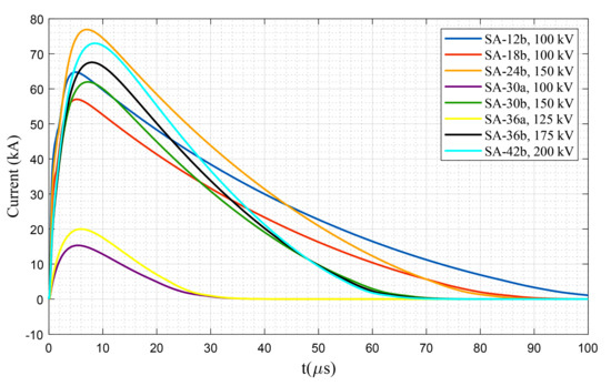
Figure 16.
Current flow through surge arresters under their highest handleable overvoltage impulse, Case 1.
3.3.2. Case 2. Transformer Protected by a Series Connection of Surge Arrester and Spark Gap
This case investigates the mutual effects of two protective devices, connected in series, on the protection of MV transformers against indirect lightning. For systems protected only by a spark gap, when this device is triggered, it acts as a short circuit, and consequently the voltage at MV terminals of the transformer reaches to zero, i.e., the voltage is chopped, and the continuous service to electricity consumers is interrupted [33]. Figure 17 presents the performance of the spark gap under different indirect lightning impulses. As can be seen from Figure 17a, the spark gap is not triggered under the 100 kV lightning impulse, and the complete waveform is transferred to the MV terminal of the transformer. However, Figure 17b shows that for the higher impulse voltages, as the triggering criteria (7) are met, the voltage is chopped, and service interruption occurs. From Figure 17b, it is deduced that the higher the lightning impulse is, the faster the spark gap is triggered to prevent complete failure. Note that to show the functionality of the spark gap upon activation and for the sake of clarity, Figure 17b only depicts the overvoltage curves for the first 5 .
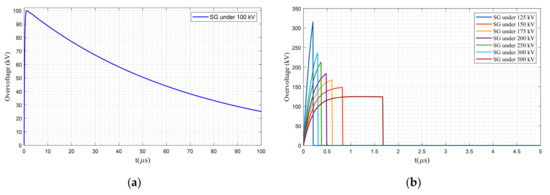
Figure 17.
Overvoltage at the spark gap (SG) terminal for (a) not triggered condition and (b) triggered condition under different lightning impulses.
However, a series connection of spark gap and surge arrester, if both are selected properly, guarantees continuous service to consumers [6]. In a series connection of spark gap and surge arrester, different conditions may occur that can be explained via the following scenarios.
- Scenario 1:Spark Gap is not triggered
In a series connection of spark gap and surge arrester, if the overvoltage at the terminal of one device is not strong enough to trigger it, the current flow through the protective devices is zero. That is, under this condition, they act as an open circuit and let the whole overvoltage pass toward the MV terminals of the transformer. This can be seen in Figure 18, in which the current through the protective devices (both the surge arrester SA-12a and spark gap) is zero during the 100 kV lightning impulse. This happens since the amplitude of lightning impulse is lower than the onset voltage of the spark gap (112 kV) and cannot trigger the spark gap. Therefore, the surge arrester does not work as well, and this can be seen by monitoring the energy absorbed by the surge arrester, which is zero during the lightning. This case shows that unlike Case 1 that the failure of surge arrester SA-12a causes a service interruption (see Figure 11a), a series combination of surge arrester and spark gap under the 100 kV lightning impulse prevents such an unwanted service interruption to the electricity consumers.

Figure 18.
Performance of surge arrester and spark gap connected in series; scenario 1, SA-12a under 100 kV lightning impulse.
- Scenario 2:Spark Gap is triggered and Surge Arrester is pushed into Failure
As in series connection of spark gap and surge arrester, the spark gap is triggered by a high voltage (above the onset voltage, which is 112 kV in this paper), a large current flows through the surge arrester and its protective role to attenuate the overvoltage stress is started. At this stage, the thermal energy absorption limit of the surge arrester is an important feature guaranteeing to provide continuous service to electricity consumers. If the failure occurs, the surge arrester will be short-circuited, and service interruption results. Point (1) in Figure 19 shows the time and corresponding overvoltage in which the spark gap is triggered, and the voltage dropped instantaneously to about 77 kV (see point (2)), where the current increased to ~48 kA. At this point, the surge arrester started its crucial role in preventing a short circuit condition. However, as can be seen in Figure 19, at point (3), the surge arrester has been pushed into a failure, and such a failure in the surge arrester caused a complete short circuit, and consequently, a service interruption resulted.
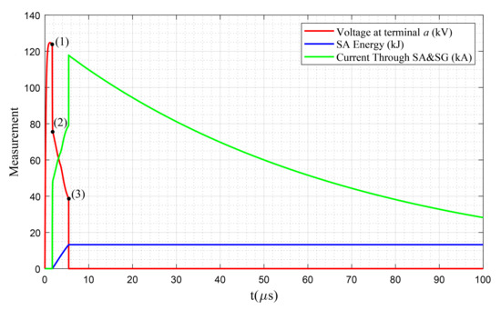
Figure 19.
Performance of surge arrester and spark gap connected in series; scenario 2, SA-12a under 125 kV lightning impulse.
It is noteworthy to mention that in some works, the thermal energy absorption limit is neglected, and consequently, an imprecise conclusion is that the spark gap always enhances the protective performance of the surges arrester since the spark gap triggers to take away the overvoltage stress from the surge arrester and surge arrester can absorb the energy without any limit, and no interruption occurs. However, as has been shown in this case, each surge arrester has a thermal absorption limit, so any extra energy results in a failure and service interruption.
- Scenario 3:Spark gap is triggered and Surge Arrester works properly
This condition is the most proper design for a series connection of a surge arrester and a spark gap, where the spark gap provides the primary protection, and after that, the surge arrester prevents any unwanted interruption. Figure 20 presents the proper protection of MV transformers under the 150 kV lightning impulse by connecting surge arresters SA-24b with the spark gap. The spark gap is triggered at point (1) when the voltage reached to about 149 kV in less than 0.82 . Then, the voltage drops rapidly to ~134 kV by discharging current through the protective devices. At point (2), the surge arrester starts its active role in protecting the transformer, and as can be seen, the absorbed energy (blue line) reaches to about 161 kJ, which is below the maximum absorption limit for this surge arrester (168 kJ). Consequently, no service interruption occurs, while in this case, the di/dt is about 9.8 kA/.
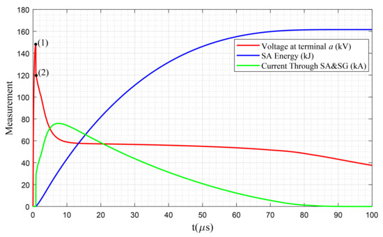
Figure 20.
Performance of surge arrester and spark gap connected in series; scenario 3, SA-24b and SA-30b under 150 kV lightning impulse.
In order to compare the performance of joint surge arrester and spark gap protection against lightning overvoltages, the proper operation of such combination is investigated. After applying different lightning impulses, the protective performance of these combined protective devices is clustered into five different categories according to the highest amplitude of lightning impulses listed in Table 2 against which proper protection is provided. The first category provides proper protection for transformers only under the 100 kV lightning impulse. This category contains six surge arresters, namely, SA-12a, SA-12b, SA-18a, SA-18b, SA-24a, and SA-30a only, and the measurements show exactly similar output as depicted in Figure 18 as they act as an open circuit and let the whole overvoltage pass toward the MV terminals of the transformer.
The second category contains only the surge arrester SA-36a that when connected with the spark gap in series, the transformer is properly protected under 125 kV lightning impulses, as presented in Figure 21. Moreover, it is evident that similar to the case with only surge arresters (see Figure 15a, a series connection of surge arrester and spark gap provide protection for 125 kV lightning impulses. In this case, the di/dt is about 3.8 kA/.
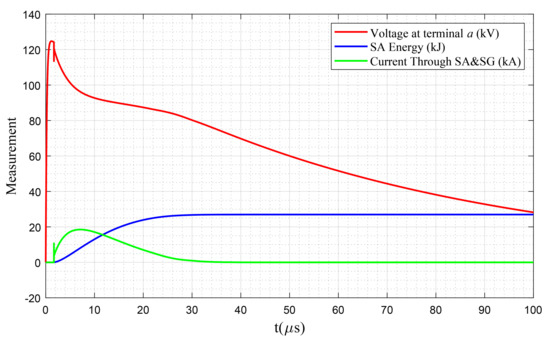
Figure 21.
Performance of surge arrester and spark gap connected in series; scenario 3, SA-36a under 125 kV lightning impulse.
Surge arresters SA-24b and SA-30b provide proper protection for MV transformers against the 150 kV lightning impulses (see Figure 20). A comparison of Figure 20 with Figure 13b and Figure 14b shows that the series combination does not provide better protective performance than utilizing only a surge arrester. Figure 22 and Figure 23 present the other two categories that provide proper protection for MV transformers against the 175 kV and 200 kV lightning impulses, respectively, with SA-36b and SA-42b. By comparing Figure 23 with Figure 8e, it can be seen that by using the spark gap, the peak of overvoltage even goes higher than utilizing only the surge arrester, which is due to triggering the spark gap. The di/dt values in Figure 22 and Figure 23 are approximately 8.7 kA/ and 8.0 kA/, respectively.
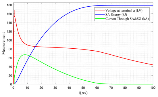
Figure 22.
Performance of surge arrester and spark gap connected in series; scenario 3, SA-36b under 175 kV lightning impulse.
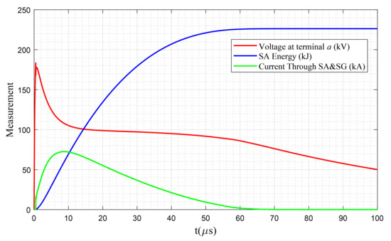
Figure 23.
Performance of surge arrester and spark gap connected in series; scenario 3, SA-42b under 200 kV lightning impulse.
From the above results, it can be seen that connecting a spark gap in series with a surge arrester prevents triggering the surge arresters for the lightning impulses with an amplitude below the onset voltage of the spark gap and therefore prevents service interruptions. However, for higher overvoltage amplitudes, it does not have a positive effect on providing better protection for the transformer. Therefore, it is required to find a better approach to control the input energy pushed into a surge arrester and thereby prolong its lifetime.
3.3.3. Case 3. Transformer Protected by Filtered Surge Arrester
A surge arrester is modeled by an RLC circuit with two nonlinear resistances Ao and A1 separated by an R-L filter, see Section 2.4.1. Therefore, using an inductor before the surge arrester may control the input energy to the surge arrester. Case 3 investigates the viability and effectiveness of this idea and reveals its pros and cons. To do so, all the surge arresters listed in Table 1 are equipped with different inductor sizes, and the absorbed energy by surge arrester, current flow through it, as well as the overvoltage stress are measured. In this paper, the inductors to be used for test purposes are 100 , 250 , 500 , and 1 .
First, the surge arrester SA-12a, which is the lowest rating surge arrester with energy class a is considered. Figure 24 a–d presents the performance of filtered surge arrester SA-12a under the 100 kV indirect lightning impulse at the presence of the aforementioned inductors. By comparing Figure 24a with Figure 11a, it can be observed that by using a 100 inductor, the high initial overvoltage (~64 kV) presented in Figure 11a has been substantially decreased to about the surge arrester residual voltage level (~31.5 kV). However, as the energy pushed into the surge arrester is higher than the thermal absorption limit, a failure, and consequently, an interruption occurs. Moreover, by using the 100 inductor, it takes ~43 until the energy pushed into the surge arrester passes the thermal absorption limit (see Figure 24a), while for the case without the inductor, the time to failure is ~6.1 . Similarly, by increasing the inductor size in Figure 24b,c, the time to failure, compared with Figure 24a, is increased. Eventually, as depicted in Figure 24d, by using an appropriate filter, i.e., 1 , the surge arrester SA-12a properly protects the MV transformer against the 100 kV lightning impulse. That is, by increasing the filter (inductor) size, the absorbed energy is reduced until which the filtered surge arrester starts functioning properly and guarantees the continuous service to the electricity consumers. The energy absorbed by the surge arrester at the presence of 1 is ~10.87 kJ, which shows a safe margin for even protecting the lightning overvoltages above 100 kV; however, it fails in providing proper protection against the 125 kV lightning impulses. The di/dt of the surge arrester under the normal condition, Figure 24d, is ~0.03 kA/.
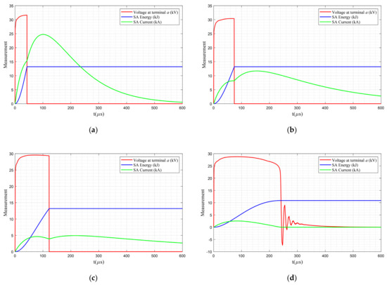
Figure 24.
Performance of filtered surge arrester SA-12a under the 100 kV lightning impulse with inductor size (a) 100 , (b) 250 , (c) 500 , and (d) 1 .
Table 3 presents the impacts of considering different filter sizes on the performance of surge arresters against indirect lightning overvoltages. This table contains the highest level of lightning impulses, among the impulses listed in Table 2, against which the surge arrester provides proper protection for MV transformers. From Table 3, it can be seen that by considering a 1 inductor to SA-12a, its performance is enhanced such that it provides similar protection as the non-filtered surge arresters SA-12b, SA-18b, and SA-30a. However, a significant improvement can be seen by considering SA-12b, where by installing only a 250 inductor, the energy pushed into the surge arrester is controlled such that it can be used instead of SA-24b and SA-30b, yet the protective performance is better than the energy class-a 36 kV rating surge arrester, i.e., SA-36a. By considering a 1 filter for SA-12b, a 100% enhancement in its protective performance is achieved. In other words, instead of using an expensive class-b surge arrester with an energy class-b 42 kV rating surge arrester, a much lower rating surge arrester with the same energy class (i.e., SA-12b) can be used.
Table 3.
Performance of surge arrester and filtered surge arrester under indirect lightning impulses.
In order to see the details of surge arrester performance enhancement, as an instance, the absorbed energy by surge arrester SA-12b under the 125 kV lightning impulse (as the risky overvoltage stress for transformers [38,39]) for different inductor sizes are compared in Figure 25. As can be seen from this figure, by using a conventional surge arrester (red curve), a voltage sag occurs at the beginning of lightning. After attenuating the voltage to ~30 kV, the surge arrester, due to absorbing more energy than its thermal absorption limit, is pushed into a failure and acts as a short circuit. Then, although even the overvoltage peak is much lower than 125 kV (~66 kV), all in all, the surge arrester is not suitable for guaranteeing a continuous service to consumers. On the other hand, it can be seen that when the surge arrester is equipped with an inductor, this newly formed filtered surge arrester provides proper protection against the 125 kV lightning surge. That is, first, the voltage sag is eliminated, and second, there will be no interruption in the supply service. Moreover, it can be deduced that by increasing the size of the filter, the peaks of the measured voltages are decreased, while the operating times of surge arrester are increased. For example, by increasing the inductor size from 100 to 250 , the peak voltage is decreased from 28.72 kV to 27.60 kV, while the operating time is increased from ~195 to ~243 .
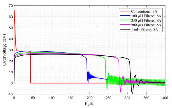
Figure 25.
Comparison of the overvoltage stress of MV transformer protected by conventional surge arrester SA-12b (no filter) and filtered surge arrester with different filter sizes under the 125 kV lightning impulse.
Table 3 can be used as a lookup table for a system operator for choosing the right surge arrester as well as to adjust the inductor size aiming at obtaining the required protection for the MV transformers. For example, if the operator decides to protect the MV transformer against a 200 kV lightning impulse, Table 3 shows several appropriate designs. The most expensive way is to install a conventional surge arrester SA-42b; however, some filtered surge arresters can also provide proper protection against lightning amplitudes similar to the 1 filtered SA-12b, 500 filtered SA-18b, 250 filtered SA-24b, 100 filtered SA-30b, and 100 filtered SA-36b. To see what is the difference among these different configurations, the overvoltage stress on the MV terminal of the transformer and the absorbed energy by surge arresters are compared.
Figure 26 shows a comparison among all the surge arresters (with or without filter) that can provide proper protection against the 200 kV lightning impulse. As can be seen from this figure, the surge arresters with lower ratings decrease the overvoltage amplitude to a greater extent than the higher rating surge arresters. For example, the 1 filtered SA-12b lowers down the overvoltage stress at the MV terminal of the transformer to about 26.9 kV (peak value), which is ~85.8% lower than the peak voltage level at the presence of 100 filtered SA-36b. However, by utilizing the lower rating filtered surge arresters, it takes more time to absorb the excess energy and attenuate the overvoltage. As an instance, in case of using the 100 filtered SA-36b, it only takes ~380 to eliminate the overvoltage stress, while for the 1 filtered SA-12b, it takes ~505 . Furthermore, this figure shows that the only conventional surge arrester (i.e., non-filtered surge arrester) that can protect the MV transformer against 200 kV lightning impulse is the SA-42b. This surge arrester, at the beginning of lightning, does not work properly, and a voltage sag with an amplitude of 174.4 kV is reached the MV terminal of the transformer. This drawback of surge arrester SA-42b can be addressed by using a 100 filter (see Figure 27), while, from Table 3, it can be seen that the proper protection against lightning amplitudes is enhanced by 50 kV (it provides proper protection against 250 kV lightning impulses). It is noteworthy to mention that for old transformers that such high overvoltage stress can be a source of failure, a filtered low rating surge arrester is even better than a high rating surge arrester since it offers a lower residual overvoltage. As an instance, the residual voltage of SA-42b is 98.7 kV, while a 500 filtered surge arrester SA-18b provides a residual voltage of 35.3 kV (see Table 1 and Figure 26).
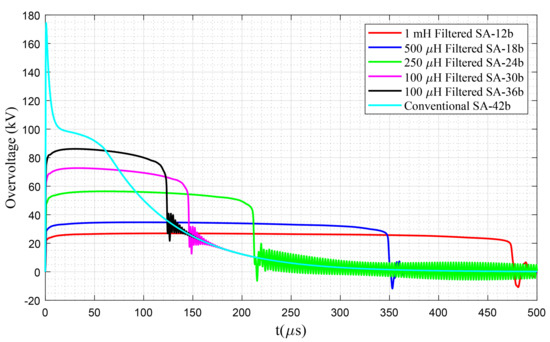
Figure 26.
Comparison of the overvoltage stress of MV transformer protected by different configurations of surge arresters against the 200 kV lightning impulse.
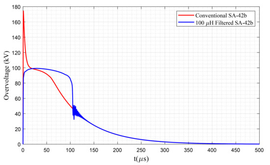
Figure 27.
Comparison of the overvoltage stress of MV transformer protected by conventional SA-42b (red curve) and 100 filtered SA-42b (blue curve) under the 200 kV lightning impulse.
Figure 28 compares the absorbed energy by different configurations of surge arresters aims at providing proper protection for MV transformers against the 200 lightning impulse. The primary conclusion of this figure is that the proper sizes of filters can significantly enhance the performance of surge arresters by preventing any unwanted failure as a result of controlling the energy pushed into the surge arrester. Note that the surge arrester SA-42b has absorbed 228.1 kJ of energy to keep the overvoltage level below the desired voltage. That is, if the other surge arresters, presented in Figure 28, had a thermal energy absorption limit above 228.1 kJ, they could have been absorbed this energy and keep the overvoltage level below their desired residual voltage level, which is way below the residual voltage of SA-42b. Such capability has been awarded to these low thermal absorption-limit surge arresters by installing a filtering device and controlling their energy level such that even SA-12b with a 1 filter can provide proper protection, yet keeping the overvoltage stress below 24.6 kV (see Figure 26), which is well below the residual voltage of SA-42b, 98.7 kV. This is an incredible achievement by which the system operators can save their equipment against lightning overvoltages with a lower rating surge arresters, and consequently save a great amount of money.
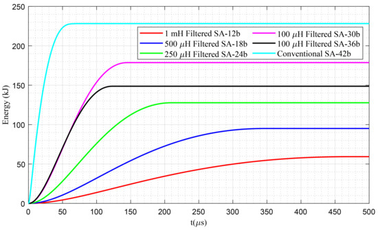
Figure 28.
Comparison of the energy absorbed by different surge arresters against the 200 kV lightning impulse.
Figure 29 presents the current flowing through the filtered surge arresters under the highest handleable overvoltage impulse, see Table 3. The range of di/dt of the filtered surge arresters under such a condition is between about 0.04 kA/ and 0.11 kA/. This range, compared with the reported di/dt in Case 1 and Case 2, shows a resounding performance of the filter in mitigating the steepness of the current, and consequently decreasing the stress over the surge arrester, which enhances the performance of this protective device.
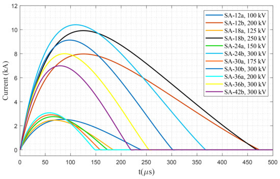
Figure 29.
Comparison of the current flow through different surge arresters against the highest handleable lightning impulse.
In order to show the impact of different filters on di/dt of the surge arrester, SA-42b is tested under the 200 kV impulse (the impulse that can be handled via the conventional SA-42b, see Table 3), and results are depicted in Figure 30. As can be seen from this figure, the current flow through the surge arrester without any filter reached to about 73 kA with a di/dt of about 8 kA/, but after considering the 100 filter, the current has been limited to ~18 kA (i.e., an ~75.3% decrement) and the di/dt has been decreased to ~0.42 kA/. By applying the 250 , 500 , and 1 mH filters, the current decrease to about 9.8 kA, 5.8 kA, and 2.5 kA, respectively, with the di/dt of about 0.19 kA/, 0.09 kA/, and 0.04 kA/. Results confirm the superiority of using filtered surge arrester over the conventional one.
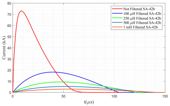
Figure 30.
Comparison of the current flow through surge arresters SA-42b against the 200 kV lightning impulse under different filtering conditions.
It is noteworthy to mention that equipping the surge arresters with an inductor-based filter does not alter the residual voltage of surge arresters. This can be seen by comparing the residual voltage presented in Figure 26 with the residual voltage of each surge arrester in Table 1. The filtering devices, by controlling the energy pushed into the surge arrester, enhance their performances against lightning surges with higher overvoltage amplitudes, and in some cases, they eliminate the unwanted voltage sags, besides, they highly decrease the steepness of the current flow through the surge arrester.
3.3.4. Case 4. Transformer Protected by the Series Connection of Filtered Surge Arrester and Spark Gap
This case investigates the impact of a joint filtered surge arrester and spark gap on the protection against indirect lightning impulses. It is worth mentioning that the same scenarios presented in Case 2 (see Section 3.3.2) are also valid for this case. However, the focus of this case is to show the impact of the spark gap on enhancing the overvoltage stress and absorbed energy by surge arrester, compared to Case 3 (see Section 3.3.3). To this end, the performances of surge arresters presented in Figure 26 (which provided proper protection against the 200 kV lightning impulse without considering the spark gap) are studied at the presence of a joint filtered surge arrester and spark gap.
Figure 31a–f provides a comparison among the protection mechanisms of the filtered surge arrester and joint filtered surge arrester and spark gap against a 200 kV lightning impulse. In this figure, the solid curves present the measurements made at the presence of filtered surge arresters, while the dashed curves stand for the measurements made at the presence of a filtered surge arrester and spark gap. Note that Figure 31f presents the protection mechanisms of protecting devices with conventional (non-filtered) surge arrester SA-42b. As can be seen from the configurations in which a filter has been used (Figure 31a–e), the main difference between the protection mechanisms of filtered surge arrester (solid curve) and the joint filtered surge arrester and spark gap (dashed curve) is the voltage sag resulted at the beginning of lightning due to triggering the spark gap, while the surge arrester alone does not cause such voltage sags. However, the spark has a small impact on decreasing the absorbed energy by surge arrester that increases the functionality margin against higher lightning impulses, although negligible. As an instance, in Figure 31a, the energy pushed into the surge arrester when no spark gap is considered is ~59.33 kJ, while for the case with the spark gap, the energy is decreased to ~57.65 kJ, which shows 2.83% enhancement. Moreover, for lower rating surge arresters connected with spark gaps, the operating time is a bit less than the time required by using only surge arresters (see Figure 31a–c). Such a situation is not valid for higher rating surge arresters (see Figure 31d–f).
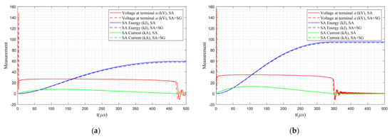
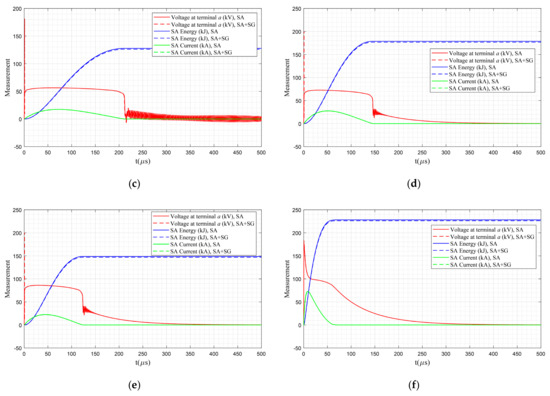
Figure 31.
Comparison of the energy absorbed by different surge arresters against the 200 kV lightning impulse: (a) 1 filtered SA-12b, (b) 500 filtered SA-18b, (c) 250 filtered SA-24b, (d) 100 filtered SA-30b, (e) 100 filtered SA-36b, and (f) non-filtered SA-42b.
Figure 31f shows the mechanism of the non-filtered surge arrester and spark gap against the 200 kV lightning impulse. Unlike Figure 31a–e, in which at the presence of the filtered surge arresters (solid lines), no voltage sag was occurring (the voltage sag was happening only at the presence of joint filtered surge arrester and spark gap), in Figure 31f, and at the presence of non-filtered surge arrester SA-42b, voltage sag is observed. To see this phenomenon more clearly, Figure 32 presents the performance of SA-42b for the first 5 of lightning impulse. As can be seen from this figure, the spark gap is triggered at ~0.5 after the lightning strike, and this results in even sharper voltage sag than the case with only surge arrester. Although triggering the spark gap decreases the energy pushed into the surge arrester (blue dashed curve), the overvoltage trends for both protection approaches (i.e., surge arrester and joint surge arrester and spark gap) after ~14 are similar (see solid and dashed red curves in Figure 31f and Figure 32).
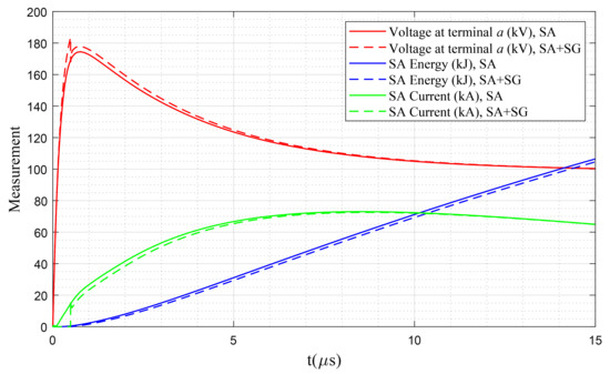
Figure 32.
Comparison of the energy absorbed by different surge arresters against the 200 kV lightning impulse.
Figure 33 presents the current flowing through the filtered surge arresters under the highest handleable overvoltage impulse, see Table 3. As can be seen, this figure resembles very much Figure 29 and just a negligible enhancement has been obtained. Therefore, in this case, the range of the di/dt is almost similar to Case 3.
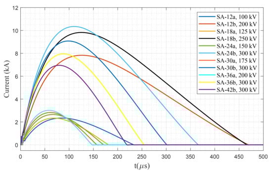
Figure 33.
Comparison of the current flow through different surge arresters against the highest handleable lightning impulse.
All in all, a limited enhancement can be achieved by considering a spark gap in series with surge arresters where the absorbed energy by the surge arrester or the current flow through them are negligibly decreased, and therefore better protection for higher lightning impulses results. It should be noted that the spark gap can play an important role during the failure of the surge arrester. Each surge arrester, if not deteriorated under overvoltage stress, needs approximately 45 to 60 min for cooling down [47], and practically it behaves as a short circuit. Therefore, the spark gap can protect the MV transformers against the lightning impulses during this cooling down period, although by interrupting the continuous service to the electricity consumers.
4. Conclusions
This work has proposed an innovative technical approach in enhancing the performance of surge arresters to protect the MV transformers against indirect lightning overvoltages. More often than not, surge arresters fail after experiencing a thermal runaway as a result of receiving higher energy than their thermal energy absorption limit. An easy way to prevent such failures is to utilize a higher rating surge arrester with a desired energy class, however, it imposes extra costs to the system operator. In this paper, an inductor has been used as a filtering device to limit the energy pushed into the surge arrester. By controlling the energy of a surge arrester, the failure is prevented, and a lower rating surge arrester can be used instead of the high rating expensive surge arresters. In order to provide in-depth analyses, the performance of eleven surge arresters with ratings from 12 kV to 42 kV with two energy classes are investigated under different lightning impulses such as 100 kV, 125 kV, 150 kV, 175 kV, 200 kV, 250 V, 30 kV, and 500 kV. The filters that have been used to control the energy levels are 100 , 250 , 500 , and 1 inductors installed before the surge arrester. Besides considering the performance of the proposed filtered surge arrester configuration, the impacts of the spark gap on the performance of this configuration have also been studied. An energy-controlled switch has been proposed to monitor the thermal energy of the surge arrester and to simulate the failure. Results show the effectiveness of equipping surge arresters with an inductor-based filter. For instance, equipping a 1 filter resulted in a considerable enhancement in the protective performance of a 12 kV rating surge arrester (i.e., SA-12b). A non-filtered surge arrester SA-12b could only protect the MV transformer against 100 kV lightning impulses, while a 1 filtered surge arrester SA-12b provides proper protection against 200 kV lightning impulses. The only non-filtered surge arrester, among the considered surge arresters in this paper, that provides proper protection against 200 kV lightning overvoltages is a 42 kV surge arrester (i.e., SA-42b), though, unlike a 1 filtered surge arrester SA-12b, it shows inappropriate protection at the beginning of 200 kV lightning overvoltages where a voltage sag is reached to the transformer terminal. Moreover, the surge arrester SA-42b can only decrease the overvoltage tension to 98.7 kV, while a 1 filtered surge arrester SA-12b keeps the overvoltage tension below 28.2 kV. It has also been shown that the spark gap installed in series with the surge arrester may help in decreasing the absorbed energy by the surge arrester only slightly. Furthermore, results confirm that by using the filtered surge arrester, the di/dt decreases significantly such that, in this work, without installing a filter, the range of di/dt used was between 5.7 kA/ and 11.0 kA/, and after considering the filtering device the range was between 0.04 kA/ and 0.11 kA/, which is yet another resounding outcome.
All in all, the results (a) show the importance of considering the thermal absorption limit of surge arrester for transient overvoltage studies, and (b) reveal that instead of using an expensive high rating surge arrester to provide proper protection for the MV transformers, a low rating surge arrester, if equipped with a proper filter, can be used. A proper filtered low rating surge arrester not only provides a similar or even better protective performance against the lightning overvoltages, but also proposes a lower residual overvoltage than the proper high rating surge arresters. Therefore, the proposed filter, by boosting the performance of surge arresters, prolongs its lifetime by limiting the energy pushed into the surge arrester and preventing any unwanted failure. Above all, installing low rating surge arresters instead of high rating surge arresters results in considerable savings for the system operator. It is noteworthy to mention that the filtering device that has been applied to modify the performance of the surge arrester might be its longitudinal withstand voltage level, limited applicability against direct lightning strikes, as well as the size. These limitations need to be studied deeply.
In future works we aim to investigate (1) the impact of the proposed filter on mitigating the effects of lead length [51] and (2) the impact of the earthing system (soil ionization) as well as the conductive coupling of the surge arresters on the performance of the proposed protective device while taking into account the aforementioned limitations.
Author Contributions
M.P.-K. proposed the main idea, developed the model, performed the simulations, and prepared the original research draft. M.L. proposed the primary modifications, validated the approach, and supervised the work. All authors have read and agreed to the published version of the manuscript.
Funding
The APC was funded by Aalto University.
Conflicts of Interest
The authors declare no conflict of interest.
References
- Visacro Filho, S. Atmospheric Discharge: An Engineering Approach (Descargas Atmosféricas: Uma abordagem de engenharia); Artliber Editora: São Paulo, Brazil, 2005; ISBN 8588098318. [Google Scholar]
- Keitoue, S.; Murat, I.; Filipović-Grčić, B.; Župan, A.; Damjanović, I.; Pavić, I. Lightning caused overvoltages on power transformers recorded by on-line transient overvoltage monitoring system. J. Energy Energ. 2018, 67, 44–53. [Google Scholar]
- Furgał, J. Influence of Lightning Current Model on Simulations of Overvoltages in High Voltage Overhead Transmission Systems. Energies 2020, 13, 296. [Google Scholar] [CrossRef]
- Sabiha, N.A.; Lehtonen, M. Overvoltage spikes transmitted through distribution transformers due to MV spark-gap operation. In Proceedings of the 2010 Electric Power Quality and Supply Reliability Conference, Kuressaare, Estonia, 16–18 June 2010; pp. 207–214. [Google Scholar]
- Heine, P.; Lehtonen, M.; Oikarinen, A. Overvoltage protection, faults and voltage sags. In Proceedings of the 2004 11th International Conference on Harmonics and Quality of Power (IEEE Cat. No.04EX951), Lake Placid, NY, USA, 12–15 September 2004; pp. 100–105. [Google Scholar]
- Mahmood, F.; Rizk, M.E.M.; Lehtonen, M. Evaluation of Lightning Overvoltage Protection Schemes for Pole-Mounted Distribution Transformers. Int. Rev. Electr. Eng. 2015, 10, 616. [Google Scholar] [CrossRef]
- Pazos, F.J.; Amantegui, J.; Ferrandis, F.; Barona, A. Overvoltages in low voltage systems due to normal medium voltage switching. In Proceedings of the 19th International Conference on Electricity Distribution (CIRED), Vienna, Austria, 21–24 May 2007; pp. 1–4. [Google Scholar]
- Meng, P.; Gu, S.; Wang, J.; Hu, J.; He, J. Improving electrical properties of multiple dopant ZnO varistor by doping with indium and gallium. Ceram. Int. 2018, 44, 1168–1171. [Google Scholar] [CrossRef]
- Opsahl, A.M.; Brookes, A.S.; Southgate, R.N. Lightning Protection for Distribution Transformers. Trans. Am. Inst. Electr. Eng. 1932, 51, 245–251. [Google Scholar] [CrossRef]
- Mikropoulos, P.N.; Tsovilis, T.E.; Koutoula, S.G. Lightning Performance of Distribution Transformer Feeding GSM Base Station. Ieee Trans. Power Deliv. 2014, 29, 2570–2579. [Google Scholar] [CrossRef]
- Cigre Working Group A2.37. Transformer Reliability Survey; Technical brochure no. 642; International Council on Large Electric Systems: Paris, France, 2015. [Google Scholar]
- Meng, P.; Yuan, C.; Xu, H.; Wan, S.; Xie, Q.; He, J.; Zhao, H.; Hu, J.; He, J. Improving the protective effect of surge arresters by optimizing the electrical property of ZnO varistors. Electr. Power Syst. Res. 2020, 178, 106041. [Google Scholar] [CrossRef]
- Meng, P.; Lyu, S.; Hu, J.; He, J. Tailoring low leakage current and high nonlinear coefficient of a Y-doped ZnO varistor by indium doping. Mater. Lett. 2017, 188, 77–79. [Google Scholar] [CrossRef]
- Meng, P.; Zhou, Y.; Wu, J.; Hu, J.; He, J. Novel ZnO Varistors for Dramatically Improving Protective Effect of Surge Arresters. In Proceedings of the 2018 34th International Conference on Lightning Protection (ICLP), Rzeszow, Poland, 2–7 September 2018; pp. 1–6. [Google Scholar]
- He, J. Metal. Oxide Varistors: From Microstructure to Macro-Characteristics; Wiley-VCH Verlag GmbH & Co. KGaA: Weinheim, Germany, 2019; ISBN 9783527684038. [Google Scholar]
- Zi-Ming, H.; Xiu-Juan, C.; Wei-Jiang, C. The Power Loss Calculation Model of Metal Oxide Resistors at Continuous Operating Voltage. In Proceedings of the 2019 11th Asia-Pacific International Conference on Lightning (APL), Hong Kong, 12–14 June 2019; pp. 1–6. [Google Scholar]
- Piantini, A.; de Carvalho, T.O.; Obase, P.F.; Janiszewski, J.M.; Santos, G.J.G.; Fagundes, D.R.; Uchoa, J.I.L.; Kunz, E.N. The effect of the distance between transformer and MV arresters on the surges transferred to the LV side. In Proceedings of the 2012 International Conference on High Voltage Engineering and Application, Shanghai, China, 17 September 2012; pp. 105–109. [Google Scholar]
- Josephine, M.M.; Ikechukwu, G.A. Performance of Surge Arrester Installation to Enhance Protection. In Proceedings of the World Congress on Engineering and Computer Science 2016 Vol I, San Francisco, CA, USA, 19–21 October 2016; pp. 1–7. [Google Scholar]
- Christodoulou, C.A.; Vita, V.; Maris, T.I. On the optimal placement of surge arresters for the efficient protection of medium voltage distribution networks against atmospheric overvoltages. In Proceedings of the 2019 54th International Universities Power Engineering Conference (UPEC), Bucharest, Romania, 3–6 September 2019; pp. 1–4. [Google Scholar]
- Firouzjah, K.G. Distribution Network Expansion Based on the Optimized Protective Distance of Surge Arresters. Ieee Trans. Power Deliv. 2018, 33, 1735–1743. [Google Scholar] [CrossRef]
- Sabiha, N.A.; Lehtonen, M. Lightning-Induced Overvoltages Transmitted Over Distribution Transformer With MV Spark-Gap Operation—Part II: Mitigation Using LV Surge Arrester. IEEE Trans. Power Deliv. 2010, 25, 2565–2573. [Google Scholar] [CrossRef]
- Somogyi, A.; Vizi, L. Overvoltage protection of pole mounted distribution transformers. Period. Polytech. Electr. Eng. 1997, 41, 27–40. [Google Scholar]
- Application Note 2.0— Metal-oxide surge arresters in medium-voltage systems. In Overvoltage Protection of Transformers; ABB Switzerland Ltd.: Baden, Switzerland, 2018.
- Piasecki, W.; Kuczek, T.; Stosur, M.; Steiger, M.; Szewczyk, M. Investigation on new mitigation method for lightning overvoltages in high-voltage power substations. Iet Gener. Transm. Distrib. 2013, 7, 1055–1062. [Google Scholar] [CrossRef]
- Visacro, S. Statistical analysis of lightning current parameters: Measurements at Morro do Cachimbo Station. J. Geophys. Res. 2004, 109, D01105. [Google Scholar] [CrossRef]
- De Conti, A.; Perez, E.; Soto, E.; Silveira, F.H.; Visacro, S.; Torres, H. Calculation of Lightning-Induced Voltages on Overhead Distribution Lines Including Insulation Breakdown. IEEE Trans. Power Deliv. 2010, 25, 3078–3084. [Google Scholar] [CrossRef]
- Kuffel, E.; Zaengl, W.S.; Kuffel, J. High. Voltage Engineering Fundamentals; Elsevier: Amsterdam, The Netherlands, 2000; ISBN 9780750636346. [Google Scholar]
- Jia, W.; Xiaoqing, Z. Double-Exponential Expression of Lightning Current Waveforms. In Proceedings of the The 2006 4th Asia-Pacific Conference on Environmental Electromagnetics, Dalian, China, 1–4 August 2006; pp. 320–323. [Google Scholar]
- Pourakbari-Kasmaei, M.; Mahmoud, F.; Krbal, M.; Pelikan, L.; Orságová, J.; Toman, P.; Lehtonen, M. Optimal Adjustment of Double Exponential Model Parameters to Reproduce the Laboratory Volt-Time Curve of Lightning Impulse. Available online: https://drive.google.com/file/d/15NgOIIbDuCZIiqTqXzC7QeMKND8O22Tj/view?usp=usp=sharing (accessed on 15 August 2020).
- Electromagnetic Transients Program-Restructured Version (EMTP-RV). Available online: https://www.emtp-software.com/ (accessed on 15 August 2020).
- Pourakbari-Kasmaei, M.; Lehtonen, M. GAMS Code for Obtaining Optimal Parameters of Double Exponential Function. Available online: https://drive.google.com/drive/folders/19IBsft1DEfb57IJ_frpmvnTRsuJn5FpN?usp=sharing (accessed on 15 August 2020).
- Cigre Working Group 02 (Internal overvoltages) Of Study Committee 33. Guidelines for Representation of Network Elements When Calculating Transients; International Council on Large Electric Systems: Paris, France, 1990; 30p. [Google Scholar]
- Pourakbari-Kasmaei, M.; Mahmood, F.; Krbal, M.; Pelikan, L.; Orságová, J.; Toman, P.; Lehtonen, M. Evaluation of Filtered Spark Gap on the Lightning Protection of Distribution Transformers: Experimental and Simulation Study. Energies 2020, 13, 3799. [Google Scholar] [CrossRef]
- Savadamuthu, U.; Udayakumar, K.; Jayashankar, V. Modified disruptive effect method as a measure of insulation strength for non-standard lightning waveforms. IEEE Trans. Power Deliv. 2002, 17, 510–515. [Google Scholar] [CrossRef]
- Darveniza, M. The generalized integration method for predicting impulse volt-time characteristics for non-standard wave shapes-a theoretical basis. IEEE Trans. Electr. Insul. 1988, 23, 373–381. [Google Scholar] [CrossRef]
- IEEE Working Group. 3.4.11: Application of Surge Protective Devices Subcommittee- Surge Protective Device Committee. Modeling of metal oxide surge arresters. IEEE Trans. Power Deliv. 1992, 7, 302–309. [Google Scholar] [CrossRef]
- Siemens Catalogue 31.1 HG Medium-Voltage Surge Arresters: Product Guide. Available online: https://assets.new.siemens.com/siemens/assets/api/uuid:a6c3362fa89bb8e6ba4c444b07ab680a87a4105a/version:0/medium-voltage-surge-arresters-catalog-hg-31-1-2017-low-resoluti.pdf (accessed on 15 August 2020).
- IEEE Standards Board. 1313-1993-IEEE Standard for Power Systems - Insulation Coordination. IEEE Std 1313-1993 1993. [Google Scholar] [CrossRef]
- Technical Specification of Transformer. Available online: https://procurement-notices.undp.org/view_file.cfm?doc_id=104038 (accessed on 15 August 2020).
- National Electrical Manufacturers Association Understanding the Arrester Datasheet. Available online: https://www.nemaarresters.org/understanding-arrester-datasheet/ (accessed on 15 August 2020).
- Göhler, R.; Hinrichsen, V. Metal-Oxide Surge Arresters in High-Voltage Power Systems: Fundamentals. Available online: https://assets.new.siemens.com/siemens/assets/api/uuid:64a37729c7408df1e15b39ca8c9cde8b957a5463/e50001-g630-h197-x-4a00-ableiterhandbuch-teil-1-a4.pdf (accessed on 15 August 2020).
- INMR Principal Failure Modes for Surge Arresters. Available online: https://www.inmr.com/principal-failure-modes-surge-arresters/#:~:text=Inmostscenarios%2Cfailureoccurs,orswitching)orlightningor (accessed on 15 August 2020).
- Novizon, N.; Malek, Z.A.; Ahmad, M.H.; Waldi, E.P.; Aulia, S.; Laksono, H.D.; Riska, N. Power loss estimation of polymeric housing surge arrester using leakage current and temperature approach. Iop Conf. Ser. Mater. Sci. Eng. 2019, 602, 012008. [Google Scholar] [CrossRef]
- Tsovilis, T.E.; Topcagic, Z. DC Overload Behavior of Low-Voltage Varistor-Based Surge Protective Devices. Ieee Trans. Power Deliv. 2020, 1. [Google Scholar] [CrossRef]
- Topcagic, Z.; Tsovilis, T.E. Varistor Electrical Properties: Microstructural Effects. In Reference Module in Materials Science and Materials Engineering; Elsevier: Amsterdam, The Netherlands, 2020. [Google Scholar]
- IEEE. 1410 IEEE guide for improving the lightning performance of electric power overhead distribution lines. IEEE Std 1410-2010 (Revision IEEE Std 1410-2004) 2011, 1–73. [Google Scholar] [CrossRef]
- Richter, B. Application Guidelines: Overvoltage Protection Metal-Oxide Surge Arresters in Medium-Voltage Systems; ABB Switzerland Ltd.: Wettingen, Switzerland, 2018. [Google Scholar]
- Cigre Working Group 01 (Lightning) of Study Committee 33 (Overvoltages and Insulation Co-ordination). Guide to Procedures for Estimating the Lightning Performance of Transmission Lines; Technical brochure no. 063; International Council on Large Electric Systems: Paris, France, 1991. [Google Scholar]
- Pourakbari-Kasmaei, M.; Mahmoud, F.; Krbal, M.; Pelikan, L.; Orságová, J.; Toman, P.; Lehtonen, M. Transformer with serial inductors and protection spark gap. Available online: https://drive.google.com/file/d/1ztdvBW2QNNZx1t6XsAY6IMTzq-nxAlVc/view?usp=sharing (accessed on 15 August 2020).
- Pourakbari-Kasmaei, M.; Mahmood, F.; Lehtonen, M. Optimized Protection of Pole-Mounted Distribution Transformers against Direct Lightning Strikes. Energies 2020, 13, 4372. [Google Scholar] [CrossRef]
- Datsios, Z.G.; Panteleimon, M.; Politis, Z.; Kagiannas, A.G.; Tsovilis, T.E. Protection of distribution transformer against arising or transferred fast-front overvoltages: Effects of surge arrester connection conductors length. In Proceedings of the 18th International Symposium on High Voltage Engineering, Seoul, Korea, 25–30 August 2013. [Google Scholar]
© 2020 by the authors. Licensee MDPI, Basel, Switzerland. This article is an open access article distributed under the terms and conditions of the Creative Commons Attribution (CC BY) license (http://creativecommons.org/licenses/by/4.0/).