Article

Image Characteristic Extraction of Ice-Covered Outdoor Insulator for Monitoring Icing Degree

1
School of Electrical and Information Engineering, Tianjin University, 92 Weijin Road, Tianjin 300072, China
2
Department of Applied Sciences, Université du Québec à Chicoutimi, Chicoutimi, QC G7H2B1, Canada
*
Author to whom correspondence should be addressed.
Energies 2020, 13(20), 5305; https://doi.org/10.3390/en13205305
Submission received: 30 August 2020 / Revised: 4 October 2020 / Accepted: 8 October 2020 / Published: 12 October 2020
(This article belongs to the Special Issue Outdoor Insulation and Gas Insulated Switchgears)

Abstract

:
Serious ice accretion will cause structural problems and ice flashover accidents, which result in outdoor insulator string operating problems in winter conditions. Previous investigations have revealed that the thicker and longer insulators are covered with ice, the icing degree becomes worse and icing accident probability increases. Therefore, an image processing method was proposed to extract the characteristics of the icicle length and Rg (ratio of the air gap length to the insulator length) of ice-covered insulators for monitoring the operation of iced outdoor insulator strings. The tests were conducted at the artificial climate room of CIGELE Laboratories recommended by IEEE Standard 1783/2009. The surface phenomena of the insulator during the ice accretion process were recorded by using a high-speed video camera. In the view of the ice in the background of the picture of fuzzy features and high image noise, a direct equalization algorithm is used to enhance the grayscale iced image contrast. The median filtering method is conducted for reducing image noise and sharpening the image edge. The maximum entropy threshold segmentation algorithm is put forward to extract the insulators and its surface ice from the background. Then, the modified Canny operator edge detection algorithm is selected to trace the boundaries of objects through the extraction of information about attributes of the endpoints of edges. After we obtained the improved Canny edge detection image for both of the ice-covered insulators and non-iced insulators, the icing thickness can be obtained by calculating the difference between the edge of the non-iced insulators image and the edge of the iced insulator image. Besides, in order to identify the icing degree of the insulators more accurately, this paper determines the location of icicles by using the region growth method. After that, the icicle length and Rg can be obtained to monitor the icing degree of the insulator. It will be helpful to improve the ability to judge the accident risk of insulators in power systems.

1. Introduction

Ice accumulation on insulator strings has been recognized as a serious threat for power systems operating in many atmospheric icing regions [1,2,3,4,5]. These hazards can be mainly divided into two categories: one is serious ice accretion, which will cause structural problems, for instance, wire breakage, tower collapse, etc., and the other is insulation problems, for instance, the icicle will change the distribution of insulators electric field significantly, which reduces its insulation performance and can lead to an ice flashover accident easily. Therefore, it is necessary to improve the ability for monitoring the operation of iced outdoor insulator strings for preventing structural accidents and icing flashover.
Over the past decades, many investigations have researched monitoring methods to reduce icing accidents [6,7,8,9,10,11,12,13,14,15,16]. In these investigations, the characteristics of iced insulators surface phenomena were extracted by image processing method for monitoring.
Liu et al. studied the performance of insulators under icing conditions, recorded the test process with a high-speed camera and analyzed the flashover characteristics of iced insulators and the growth characteristics of ice pillars based on image processing technology [17,18]. According to the characteristic value of a flashover image, the flashover process is divided into different stages, and the quantitative analysis method of flashover risk value of iced insulators is proposed. At the same time, the growth characteristics of ice pillars at different edges and the variation characteristics of surface discharge are calculated and analyzed. The research results can be used to evaluate the main hazards of iced outdoor insulators and improve the safety of iced suspension insulators. Hao et al. used the image processing method to study the natural icing of glass insulator strings in service. Based on the grab segmentation method, by identifying the convex defects of Icelandic contour, the algorithm of graphical shed spacing and graphical shed overhanging is proposed [19,20]. This method can identify the most serious icing situation when the insulator cover is completely bridged. The bridge position can also be detected, including the left, right, or both sides of the insulator string in the image. Yang et al. proposed a method for identifying the ice coating type of an in-service glass insulator based on the texture feature description operator [21]. A uniform local binary model (ULBP) and an improved uniform local binary model (IULBP) are used to extract the texture features of ice cover types. The experimental results show that, due to the different texture features of each kind of ice, IULBP has a good recognition effect on six kinds of ice. Zhu et al. proposed an image recognition algorithm for monitoring the icicle length and insulator ice bridging condition. The saliency analysis algorithm is applied to the extract region of the insulator ice layer and the length of the insulator icicle was calculated by the Fourier transform of the pixel distribution curve [22]. Pernebayeva et al. studied a Gabor filtering algorithm for extracting a set of Gabor phase congruency features from insulator images for the presence or absence of snow, ice, and water droplets by utilizing the minimum distance nearest neighbor classifier [23]. Vita, V. et al. constructed different neural network models for insulator contamination identification using different structures, learning algorithms, and transfer functions. All the models are compared and analyzed, the best model is found, and the calculation results match the experimental results [24]. Chen et al. applied digital image processing technologies such as gray level transformation, image sharpening, image segmentation, and edge detection to the research of structural images, and effectively extracted the effective information in the image [25]. Gilboa, G. et al. use the free Schrodinger equation and extended the linear and nonlinear scale space generated by the intrinsic real value diffusion equation to the complex diffusion process, thus obtaining two examples of nonlinear complex processes which play an important role in image processing: One is the regularized impact filter for image enhancement, the other is the denoising process keeping slope [26]. From comparative analysis of the research on other aspects, few investigations have been conducted on monitoring and diagnostic of insulator strings in extreme weather environments, which need further research to decrease icing accidents.
Therefore, in this paper, for improving the ability to judge the icing degree risk of outdoor insulators and reduce icing accidents caused by ice-covered insulators, the features of insulator surface performance was extracted by an image processing method in order to monitor icicle length and the ice bridging state of iced outdoor insulator strings. The tests were conducted at CIGELE Laboratories. The test specimen was the five units’ suspension ceramic insulators, which were artificially accreted with wet-grown ice in the cold-climate room of CIGELE. The procedure of ice accumulation was recommended by IEEE Standard 1783/2009. The surface phenomena of the insulators during the icing accretion were recorded by a high-speed video camera with a rate of six thousand frames per second.

2. Test Setup and Procedures

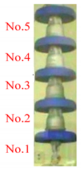
The test specimen is the five units’ suspension ceramic insulators. The picture and parameters are shown in Table 1.
The tests were conducted in an artificial climate room with a length of 4.8 m, a width of 2.8 m, and a height of 3.5 m of CIGELE Laboratories, as shown in Figure 1 [27]. By using the proportional integral and differential system, the freezing devices can make the ambient temperature drop to −12 °C after the test setup was fixed. The spray device mainly consists of a water supplying system and wind blowing equipment. Ice was formed from super-cooled droplets produced by the former system through 4 oscillating nozzles. The latter system produced a relatively uniform airflow by using a series of fans with a diffusing honeycomb panel. The test power source was supplied by an AC test transformer with a rated capacity of 240 kV·A.
The surfaces of the insulator sheds were cleaned by deionized water before the ice accretion. The insulators needed under the setting ambient temperature last about sixteen hours to give all the experimental setup enough time to reach the same temperature as that of the test environment. The AC voltage of 75 kVrms (15 kVrms per unit) was energized on insulators during ice accretion for simulating the operating environment. Meanwhile, the water supply system started to spray freezing droplets on the insulators’ surface. The water conductivity was set at 30 µS/cm by mixing deionized water and sodium chloride. The wind speed was fixed at 3.3 m/s to blow on the windward side of insulators in the ice accumulation period. When ice accumulation duration reached 90 min, the applied voltage and spray device were turned off immediately and the icing process is stopped. The ice accretion process on insulators was photographed during the whole experiment [28,29].

3. Image Processing of Ice-Covered Insulator

The iced insulator image of recording was influenced by various factors, such as the glazed icing, which is a smooth and transparent structure with unobvious transverse volume change. It is difficult to identify the overall state of iced insulators; and therefore, low quality images were attained. Therefore, in order to improve the image quality, an image processing method is proposed for recognizing the insulators’ bridged state and extracting the characteristic values for the warning of icing accidents.

3.1. Enhancement of Image

(1)
Image grayscale
Each pixel point of an iced insulator image is essentially composed of components in three directions of RGB (red, green, and blue). The grayscale is to convert the three-component value of RGB into a single gray value, so that the calculation of the subsequent image processing would be simplified. The calculation is shown in Equation (1). The result is shown in Figure 2.
M = 0.3R + 0.59G + 0.11B
here, M, R, G, and B are the values of the pixel, respectively representing gray value, red value, green value, and blue value. The coefficients in the formula are derived from the sensitivity of human eyes to color.
(2)
Gray Stretch
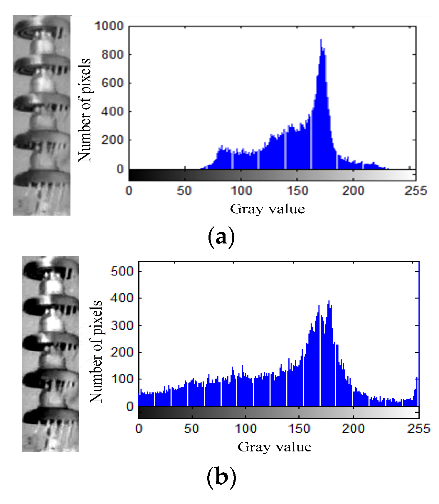
The image of the iced insulator has the characteristics of fuzziness and noise in the image background. The direct equalization method was selected to make a gray value of the image uniform distribution for enhancing contrast and highlighting the iced insulator image details. The result is shown in Figure 3.
(3)
Image denoise
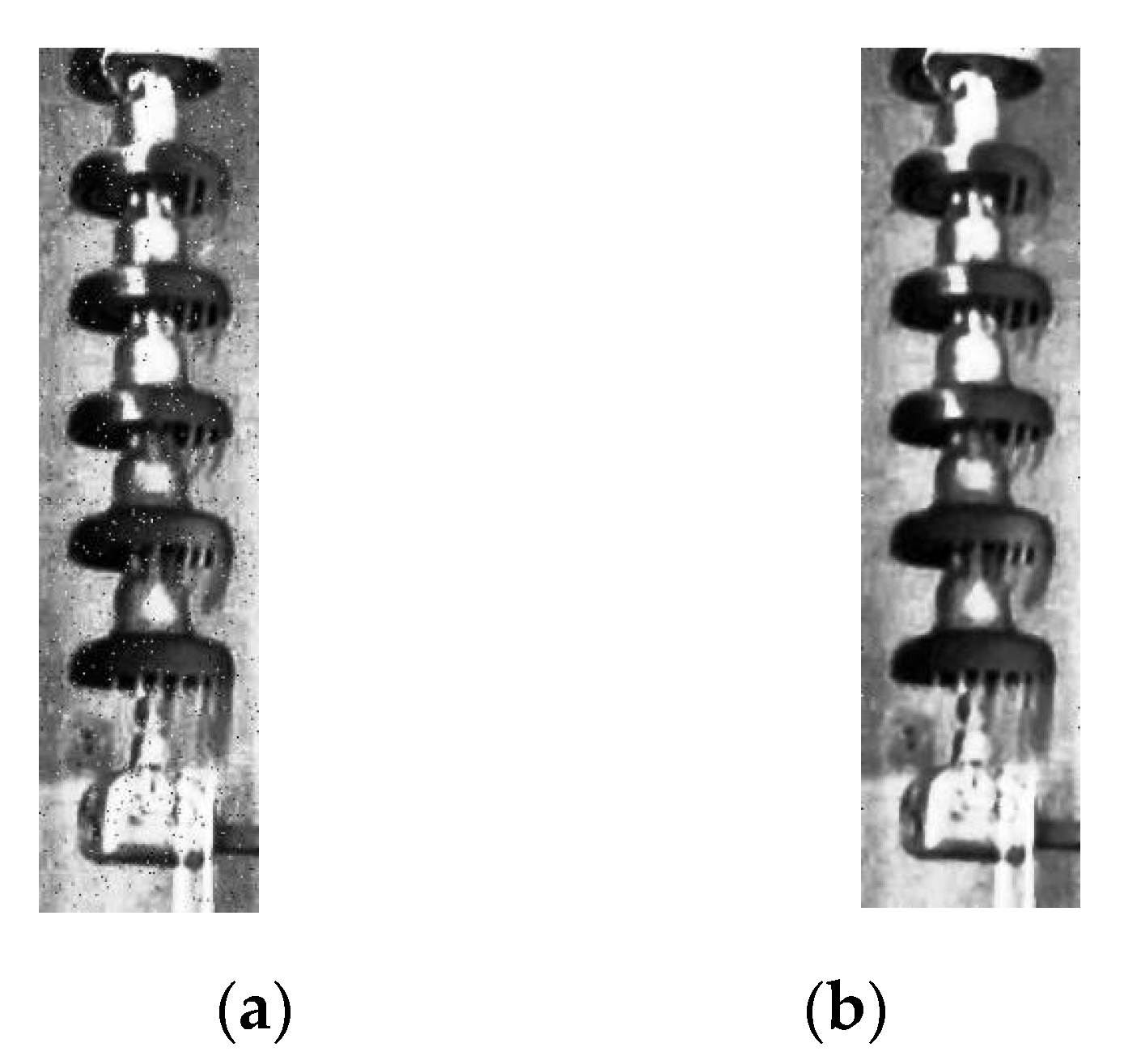
In fact, after the direct equalization processing, the noise interference is still present in the iced insulator image. To remove the small bright spot and improve the definition of image, the median filtering algorithm method was chosen to diminish the gap of the image. The iced insulator image edge can be sharpened, and the obvious background noise can be decreased through enhancing the filtering effect. The result is shown in Figure 4.

3.2. Image Segmentation

(1)
Maximum entropy threshold segmentation
The key of image processing is image segmentation, which is to segment an image into meaningful regions by extracting some target area of image characteristics, and then obtain the binarization image [16,17]. The maximum entropy threshold segmentation algorithm was proposed for acquiring excellent efficacy of segmentation and the characteristics of recorded images during the ice regime. This method is essentially using the images’ regional features to segment images based on the similarity between the pixels. The higher entropy value of the segmentation image can indicate the more information it contains, and it is beneficial to the effect of division [18]. The calculation formula of entropy is
H ( S ) = P 1 ln P 1 P 0 ln P 0
where H(s) is the statistical value of the amount of information that the binarization image contained after segmentation. P1 and P0 represent the probability that the output value of the segmentation image is one and zero, respectively.
According to the effective segment, the gray value of the image is compressed and transformed into 0 or 255 pixel values. Then, the approximate edge contours are obtained and the process of binarization is completed. The image processing result is shown in Figure 5. It can be observed that the maximum entropy threshold segmentation method can extract the object points of the image and remove the redundant information. Therefore, the proposed algorithm ensures the segmentation more efficient and segments insulator images with intensity inhomogeneity correctly.
(2)
Edge detection
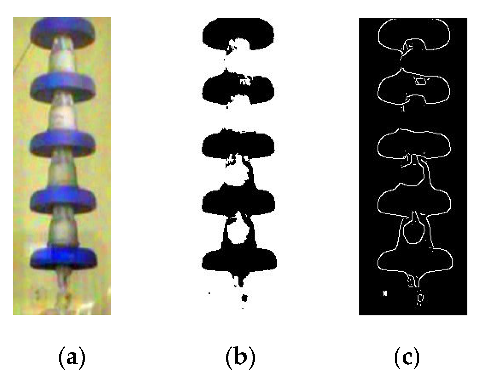
Figure 5 shows that there is still background noise in the image and the objectives and background of the segmentation image have low contrast. Thus, the modified Canny operator edge detection algorithm is selected to trace boundaries of objects through extraction of information about attributes of endpoints of edges, in particular orientation and neighborhood relationships [19,20]. In the algorithm, the image is smoothed by Gaussian filter which is used to determine the adjustable parameters based on the characteristics of the image. Most of the background is divided according to the information of the image edge for reducing imprecise background and objective. Then, the image edge can be detected by using Canny operator. The image processing result is shown in Figure 6.
The modified Canny algorithm is used to calculate the amplitude of the gradient through the directional derivatives for pixels of the image G(i,j) in the selected neighborhood. Equations (3)–(9) are as follows:
The calculation of the X directional derivative:
G x ( i , j ) = F ( i + 1 , j ) F ( i 1 , j )
The calculation of the Y directional derivative:
G y ( i , j ) = F ( i , j + 1 ) F ( i , j 1 )
The calculation of the 45° directional derivative:
G 45 ( i , j ) = F ( i + 1 , j + 1 ) F ( i 1 , j 1 )
The calculation of the 135° directional derivative:
G 135 ( i , j ) = F ( i 1 , j + 1 ) F ( i + 1 , j 1 )
The calculation of the first partial derivatives:
E x = G x ( i , j ) + G 45 ( i , j ) + G 135 ( i , j ) 2
E y = G y ( i , j ) + G 45 ( i , j ) G 135 ( i , j ) 2
The calculation of the gradient magnitude:
A ( i , j ) = E x 2 + E x 2
(3)
Region growth method
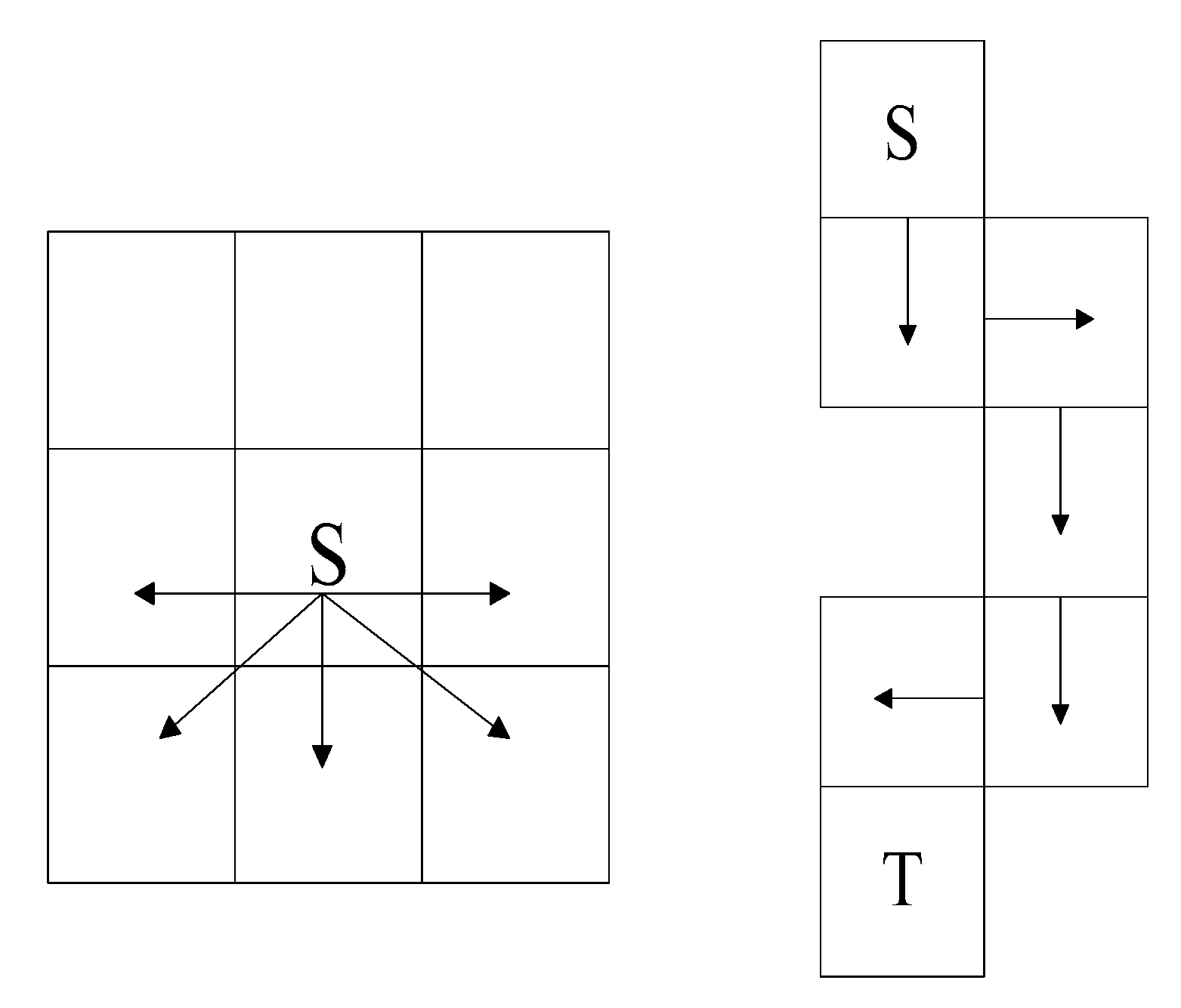
After obtaining the improved Canny edge detection images, the icing thickness can be obtained by calculating the difference between the edge of the non-iced insulator image and the edge of the iced insulator image. Besides, in order to obtain the icicles and air gap parts of the ice-covered insulators’ image for identifying the icing degree of the insulators more accurately, this paper determines the location of icicles by using the regional growth method, the schematic diagram as shown in Figure 7.
Regional growth corresponds to the process of development of a set of pixels and regions extend to a larger area. Each pixel of the edge of the non-ice shed parts of ice-covered insulators is set as the seed pixel, which is used as the starting point of growth. By inspecting the pixel value of all direction point of neighborhoods, when the pixel value of neighborhood point is the same as the pixel value of seed point, this point is defined as a new seed point. The neighborhood point will be searched continuously until it cannot satisfy the above condition. Due to the fact that the direction of the edge region of the iced insulators image is downward, the point of the top directional can be eliminated. After the process of regional growth method, it can be considered that the selected points are the tip of icicle, and then it separates the tip of icicle part and the air gaps according to the location point of the tip of icicle.
The distance between the tip of icicle and the edge of insulator is considered the air gap length. However, the pixel value of the air gap length obtained by the Canny edge detection image method needs to be transformed in millimeters for further accurate calculation. However, the air gap length cannot be used as the only parameter to indicate the icing degree of insulators because of it is impacted by the different insulator models and angles of camera recording. Thus, the icing degree is indicated by the Rg (the ratio of the air gap length to the insulator length) for avoiding the influence of these factors. Then, we can establish the relationship between the icing degree and the Rg.

4. Analyze the Results of Characteristic Extraction

The results of ice thickness, icicle length, and Rg are as shown in Table 2.
As shown in Table 2, it can be found that non-uniformity distribution of ice accretion on the surface of insulators and the ice is mainly accumulated on the windward side of insulators. When the cold room maintains the ambient temperature at −12 °C, the low-temperature droplets frozen on the surface of insulator sheds under the experimental condition. The ice thickness shows the nonlinear increasing tendency on the sheds of insulators during the process of ice accumulation. From 0 min to 20 min, the ice thickness increased slowly, only 7 mm. While from 30 min to 50 min, ice thickness increased 64 mm, the increment is about 9 times higher than the former, which indicates that the ice layer grew rapidly and the insulators’ icing degree became more serious during this period.
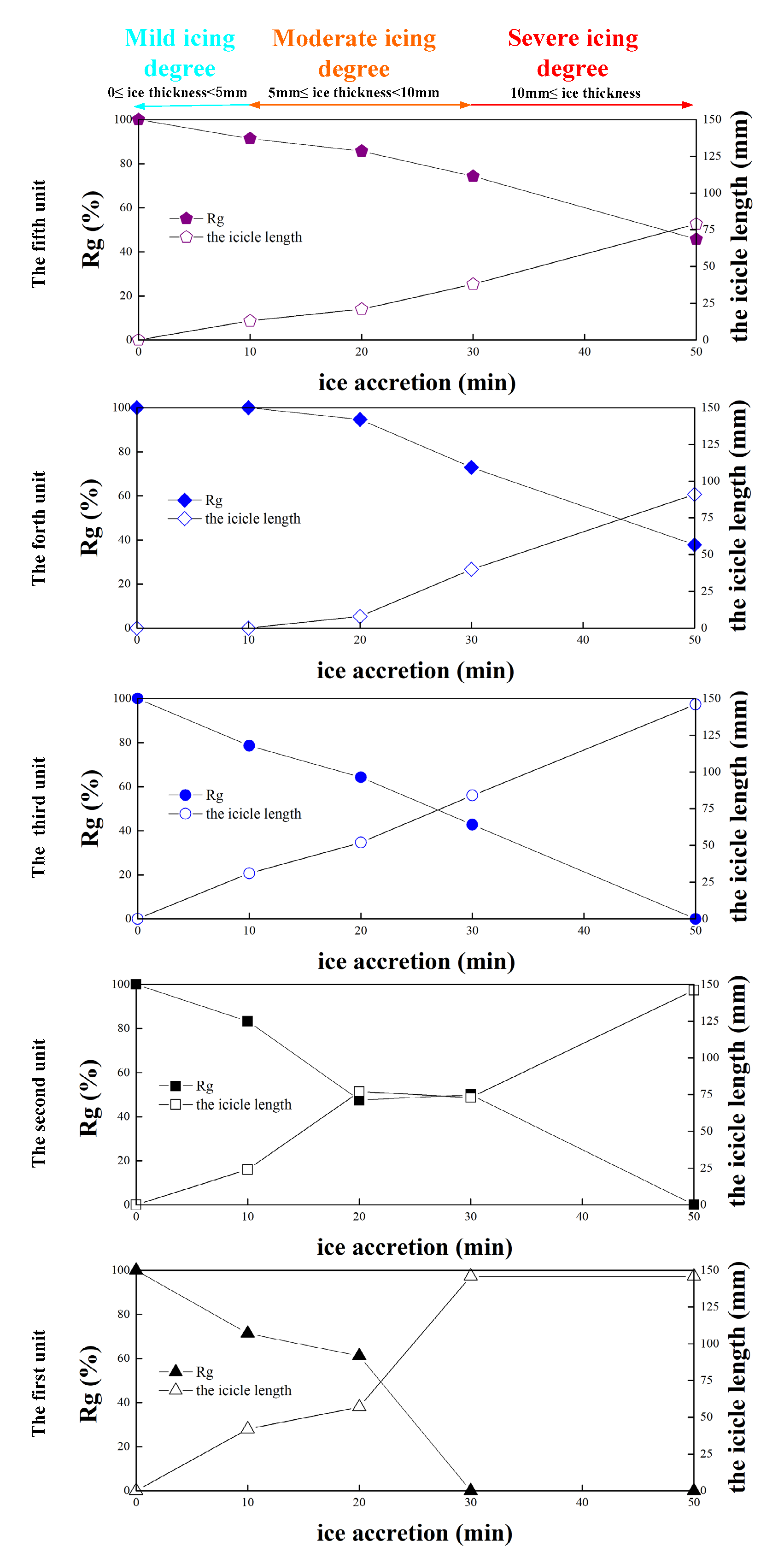
The variation of icicle length and Rg during ice accretion regime is shown in Figure 8. The super-cooled droplet formed ice, and simultaneously, the test voltage produced joule heat which can cause the melting and dripping of accreted ice. Hence, the ice accreted on the insulators is a dynamically varying phenomenon. However, each shed of the ice-covered insulators shows an obvious decreasing tendency of the variation of icicle length and Rg because of the serious degree of icing effect. Note that the icicle length of the second unit of insulators slightly decreases and Rg slightly increases between 20 min and 30 min. In this period, leakage current generated by heat energy can cause the melting of icicles and can even make some of them fall down to the ground. Although the electric field distortion of the insulator surface will increase further and the thermal effect of the arc discharge will have a negative influence on the ice accumulation, the freezing influence of precipitated droplets dominates the shed surface so the ice layer can maintain growth and the icicle length can keep increasing and Rg still can decrease at this time. Therefore, the variations of icicle length and Rg correspond well to the ice accretion process, which can be used to judge the risk of the icing degree.
In addition, from the HV (high voltage) electrode to the ground side, the shed separation between cap-and-pin insulators is significantly reduced by the increasing of icicles. Because the super-cooled droplet was subjected to the effect of gravity, the ice bridging condition of the bottom side of the insulator string units are heavy. At 30 min, the average ice thickness just reaches 24 mm, the value of the Rg between the second unit and the fifth unit of the ice-covered insulators is more than 40%, the first unit of ice-covered insulators Rg is 0%, which indicates the icing degree from the first unit to HV electrode is extremely serious. At 50 min, the first unit and the third unit are fully bridged. While the fourth and fifth units are without complete bridging, the value of Rg is 37.8 and 45.7% respectively. Meanwhile, the partial arcs constantly burn at the air gaps, which inhibits the growth of the icicles. Finally, the ice growth rate and the melting rate will reach a balance state that causes these units to be unable to be bridged completely. By analyzing the icing degree of every unit of the insulator string, we can evaluate the hazards of ice-covered insulators accurately.
In this way, through the independent analysis of the icing degree of different insulator sheds, the icing degree of insulators can be evaluated more accurately, which avoids the simple generalization of icing conditions of different types of insulators under the same environmental conditions, enhances the detailed judgment of the icing degree of insulators, and reduces the estimation error of the icing degree.
Because most of the transmission lines are exposed in the field, the monitoring equipment also needs to be exposed in the field for a long time, which will inevitably be affected by severe weather such as strong wind, high temperature, and rainstorms. There are still a series of problems in security protection, energy consumption, wireless communication, data encryption, and video image compression. In short, there will be some obstacles to the implementation of the method in this paper, but this is mainly a technical problem. With the development of science and technology, these obstacles will be solved one by one. At the same time, when dealing with different background noise, we can improve the denoising method. We can judge the type of noise by intelligent algorithms and select the corresponding denoising method automatically. The practical application of this method needs further research.

5. Conclusions

The image processing technology is used to process the icing image of the insulator, extract the characteristics of the icing degree of the iced insulator, and analyze the icing characteristics of the insulator. The proposed method will be helpful to the monitoring of the icing degree of the iced insulator. The main conclusions are as follows
(1)
Aiming at the problems of fuzzy background and noise interference of the iced insulator image, the direct equalization method, and median filter method are proposed to preprocess the image. The method can effectively reduce the noise and enhance the contrast of the image, which is of great significance for further processing the image of the iced insulator.
(2)
The maximum entropy threshold segmentation algorithm is used to extract the insulator and its surface ice from the image, and the key information is accurately screened out from the image. An improved Canny operator edge detection algorithm is used to track the edge of the non-icing insulator image and calculate the icing thickness of icing insulator image edge, which can accurately detect the insulator edge smoothly.
(3)
A regional growing method is proposed to determine the location of icicles, so as to obtain the ice column and air gap in the image of the iced insulator, and then extract the icicle length and RG as the indication value to evaluate the ice bridge state of the insulator string. The analysis results show that once the total length of ice pole exceeds 402 mm and the RG value is lower than 44.9%, the higher the accident probability of iced insulator.

Author Contributions

Y.L., Q.L. conceived and designed the study. Y.L., Q.L. analyzed the results. Q.L. drafted this article. M.F., and B.X.D. made the critical and final reviewing. All authors have read and agreed to the published version of the manuscript.

Funding

This research was funded by Chinese National Natural Science Foundation grant number 51277131, National Basic Research Program of China grant number2014CB239501 and 2014CB239506, and Natural Science Foundation of Tianjin grant number 16JCQNJC06800.

Conflicts of Interest

The authors declare no conflict of interest.

References

  1. Farzaneh, M. Insulator Flashover Under Icing Conditions. IEEE Trans. Dielectr. Electr. Insul. 2014, 21, 1997–2001. [Google Scholar] [CrossRef]
  2. Farzaneh, M. 50 Years in Icing Performance of Outdoor Insulators. IEEE Electr. Insul. 2014, 30, 14–24. [Google Scholar] [CrossRef]
  3. Jiang, X.; Meng, Z.; Zhang, Z.; Hu, J. DC Ice-Melting and Temperature Variation of Optical Fibre for Ice-Covered Overhead Ground Wire. IET Gener. Transm. Distrib. 2016, 10, 352–358. [Google Scholar] [CrossRef]
  4. Liu, Y.; Du, B. Recurrent Plot Analysis of Leakage Current on Flashover Performance of Rime-Iced Composite Insulator. IEEE Trans. Dielectr. Electr. Insul. 2010, 7, 465–472. [Google Scholar] [CrossRef]
  5. Yang, H.; Pang, L.; Li, Z.; Zhang, Q.; Yang, X.; Tang, Q.; Zhou, J. Characterization of Pre-Flashover Behavior Based on Leakage Current Along Suspension Insulator Strings Covered with Ice. IEEE Trans. Dielectr. Electr. Insul. 2015, 22, 941–950. [Google Scholar] [CrossRef]
  6. Ale-Emran, S.; Farzaneh, M. Experimental Design of Booster Shed Parameters for Post Station Insulators Under Heavy Icing Conditions. IEEE Trans. Power Deliv.. 2015, 30, 488–496. [Google Scholar] [CrossRef]
  7. Shu, L.; Shang, Y.; Jiang, L.; Hu, Q.; Yuan, Q.; Hu, J.; Zhang, Z.; Zhang, S.; Li, T. Comparison Between AC and DC Flashover Performance and Discharge Process of Ice-Covered Insulators Under the Conditions of Low Air Pressure and Pollution. IET Gener. Transm. Distrib. 2012, 6, 884–892. [Google Scholar] [CrossRef]
  8. Taheri, S.; Farzaneh, M.; Fofana, I. Empirical Flashover Model of EHV Post Insulators Based on ISP Parameter in Cold Environments. IEEE Trans. Dielectr. Electr. Insul. 2016, 23, 403–409. [Google Scholar] [CrossRef]
  9. Hu, Q.; Wang, S.; Shu, L.; Jiang, X.; Liang, J.; Qiu, G. Comparison of AC Icing Flashover Performances of 220 Kv Composite Insulators With Different Shed Configurations. IEEE Trans. Dielectr. Electr. Insul. 2016, 23, 995–1004. [Google Scholar] [CrossRef]
  10. Farzaneh, M.; Drapeau, J. AC Flashover Performance of Insulators Covered With Artificial Ice. IEEE Trans. Power Deliv. 1995, 10, 1038–1051. [Google Scholar] [CrossRef]
  11. Yan, B.; Wang, B.; Zhu, L.; Liu, H.; Liu, Y.; Ji, X.; Liu, D. A Novel, Stable, And Economic Power Sharing Scheme for an Autonomous Microgrid in the Energy Internet. Energies 2015, 8, 12741–12764. [Google Scholar] [CrossRef] [Green Version]
  12. Phan, C.; Hara, M. Leakage Current and Flashover Performance of Iced Insulators. IEEE Trans. Power Appl. Syst. 1979, 98, 849–859. [Google Scholar] [CrossRef]
  13. Hong, Y.Y.; Wei, Y.H.; Chang, Y.R.; Lee, Y.D.; Liu, P.W. Fault Detection and Location by Static Switches in Microgrids Using Wavelet Transform and Adaptive Network-Based Fuzzy Inference System. Energies 2014, 7, 2658–2675. [Google Scholar] [CrossRef] [Green Version]
  14. Meghnefi, F.; Volat, C.; Farzaneh, M. Temporal and Frequency Analysis of the Leakage Current of a Station Post Insulator during Ice Accretion. IEEE Trans. Dielectr. Electrl. Insul. 2007, 14, 1381–1389. [Google Scholar] [CrossRef]
  15. Volat, C.; Meghnefi, F.; Farzaneh, M.; Ezzaidi, H. Monitoring Leakage Current of Ice-Covered Station Post Insulator using Artificial Neural Networks. IEEE Trans. Dielectr. Electr. Insul. 2010, 17, 43–450. [Google Scholar] [CrossRef]
  16. Liu, Y.; Gao, P. Icing Flashover Characteristics and Discharge Process of 500 kV AC Transmission Line Suspension Insulator Strings. IEEE Trans. Dielectr. Electr. Insul. 2010, 17, 434–442. [Google Scholar] [CrossRef]
  17. Liu, Y.; Farzaneh, M.; Du, B. Investigation on Shed Icicle Characteristics and Induced Surface Discharges Along a Suspension Insulator String During Ice Accretion. IET Gener. Transm. Distrib. 2017, 11, 1265–1269. [Google Scholar] [CrossRef]
  18. Li, Q.; Liu, Y.; Farzaneh, M.; Du, B. Image Characteristic Extraction of Surface Phenomena for Flashover Monitoring of Ice-Covered Outdoor Insulator. In Proceedings of the International Conference on Electrical Materials and Power Equipment, Guangzhou, China, 7–10 April 2019; pp. 431–434. [Google Scholar]
  19. Hao, Y.; Wei, J.; Jiang, X. Icing Condition Assessment of in-Service Glass Insulators Based on Graphical Shed Spacing and Graphical Shed Overhang. Energies 2018, 11, 318. [Google Scholar] [CrossRef] [Green Version]
  20. Wei, J.; Hao, Y.; Fu, Y. Detection of Glaze Icing Load and Temperature of Composite Insulators Using Fiber Bragg Grating. Sensors 2019, 19, 1321. [Google Scholar] [CrossRef] [PubMed] [Green Version]
  21. Yang, L.; Jiang, X.; Hao, Y. Recognition of Natural Ice Types on in-Service Glass Insulators Based on Texture Feature Descriptor. IEEE Trans. Dielect. Elect. Insul. 2017, 24, 535–542. [Google Scholar] [CrossRef]
  22. Zhu, Y.; Liu, C.; Huang, X.; Zhang, X. Research on Image Recognition Method of Icicle Length and Bridge State on Power Insulators. Access 2019, 7, 183524–183531. [Google Scholar] [CrossRef]
  23. Pernebayeva, D.; James, A.; Bagheri, M. Live line snow and ice coverage detection of ceramic insulator using Gabor image features. In Proceedings of the IET International Conference on Resilience of Transmission and Distribution Networks, Birmingham, UK, 26–28 September 2017; pp. 1884–2021. [Google Scholar]
  24. Vita, V.; Ekonomou, L.; Chatzarakis, G.E. Design of artificial neural network models for the estimation of distribution system voltage insulators’ contamination. In Proceedings of the Wseas International Conference on Mathematical Methods. World Scientific and Engineering Academy and Society (WSEAS), Sousse, Tunisia, 3–6 May 2010; pp. 3–6. [Google Scholar]
  25. Chen, Y.; Liu, H. Study on the meso-structure image of shale based on the digital image processing technique. In Proceedings of the 2009 International Conference on Image Analysis and Signal Processing, Taizhou, China, 11–12 April 2009; pp. 150–153. [Google Scholar] [CrossRef]
  26. Gilboa, G.; Sochen, N.; Zeevi, Y.Y. Image Enhancement and Denoising by Complex Diffusion Processes. IEEE Trans. Patt. Anal. Mach. Intel. 2004, 26, 1020–1036. [Google Scholar] [CrossRef] [PubMed]
  27. IEEE. Standard 1783/2009TM, Guide for Test Methods and Procedures to Evaluate the Electrical Performance of Insulators In Freezing Conditions; IEEE: Piscataway, NJ, USA, 2009. [Google Scholar]
  28. Farzaneh, M.; Zhang, J.; Chen, X. Modeling of the AC Arc Discharge on Ice Surfaces. IEEE Trans. Power Deliv. 1997, 12, 325–338. [Google Scholar] [CrossRef]
  29. Farzaneh, M.; Baker, T.; Bernstorf, A.; Brown, K. Insulator Icing Test Methods and Procedures: A Position Paper prepared by the IEEE Task Force on Insulator Icing Test Methods. IEEE Trans. Power Deliv. 2003, 18, 1503–1515. [Google Scholar] [CrossRef]
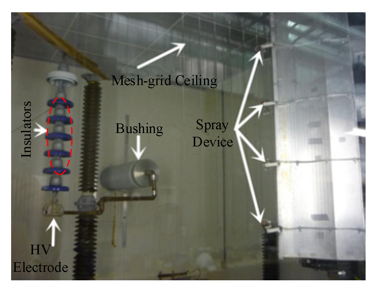
Figure 1. Artificial cold-climate room.
Energies 13 05305 g001
Figure 2. Color image and grayscale image.
Energies 13 05305 g002
Figure 3. The grayscale image and the image after direct equalization and its histogram of grayscale distribution. (a) Original grayscale image and its histogram. (b) Grayscale image and its histogram after direct equalization.
Energies 13 05305 g003
Figure 4. The image with noise interference and the image after median filtering processing. (a) The image with noise interference. (b) The image after median filtering processing.
Energies 13 05305 g004
Figure 5. The binarization image after maximum entropy threshold segmentation processing.
Energies 13 05305 g005
Figure 6. The comparison diagram of the original image and the binarization image and the image after edge detection processing. (a) Original image. (b) Binarization image. (c) Image after edge detection processing.
Energies 13 05305 g006
Figure 7. Regional growth method diagram.
Energies 13 05305 g007
Figure 8. The variation of icicle length and Rg during the ice accretion regime.
Energies 13 05305 g008
Table 1. Configuration, dimensions, and parameters of each unit of the test specimen.
Main Dimension and ParametersConfiguration
Diameter = 254 mm Energies 13 05305 i001
Height = 146 mm
Leakage distance = 305 mm
Number of units = 5 units
Arcing distance for 5 units = 809 mm
Table 2. The results of ice thickness, icicle length, and Rg.
Image of Ice-Covered Insulators Energies 13 05305 i002 Energies 13 05305 i003 Energies 13 05305 i004 Energies 13 05305 i005 Energies 13 05305 i006
Ice accretion time (min)010203050
Ice thickness (mm)0372488
NO.5Icicle length (mm)013213879
Rg(%)10091.485.774.345.7
NO.4Icicle length (mm)0084091
Rg(%)10010094.672.937.8
NO.3Icicle length (mm)0315284146
Rg(%)10078.664.342.80
NO.2Icicle length (mm)0247773146
Rg(%)10083.347.6500
NO.2Icicle length (mm)04257146146
Rg(%)10071.461.200
NO.1Icicle length (mm)0142211402624
Rg(%)10080.571.244.914.6