Article

A Definitive Model of a Small-Scale Concentrated Solar Power Hybrid Plant Using Air as Heat Transfer Fluid with a Thermal Storage Section and ORC Plants for Energy Recovery

by
Andrea Cinocca
*,
Marco Di Bartolomeo
,
Roberto Cipollone
and
Roberto Carapellucci
Department of Industrial and Information Engineering and Economics, University of L’Aquila, 67100 L’Aquila, Italy
*
Author to whom correspondence should be addressed.
Energies 2020, 13(18), 4741; https://doi.org/10.3390/en13184741
Submission received: 31 July 2020 / Revised: 2 September 2020 / Accepted: 9 September 2020 / Published: 11 September 2020

Abstract

:
The aim of this work was to propose a small-scale Concentrated Solar Power plant using conventional technologies, in order to improve their flexibility and performances, and reinforce their competitiveness compared to traditional systems. Additionally, this study analyzed the possibility of providing continuity of energy production through an optimized hybrid system, which considered thermal energy storage from a gaseous Heat Transfer Fluid, air. It also considered the possibility of recovering part of the energy of the thermodynamic cycle through an Organic Rankine Cycle system with appropriate dimensions. The final outcomes were a 170 kW CSP plant with about 805 MWh of annual electricity production with a global solar capacity of 32.5%, about 900 kWh of thermal storage daily capacity, and an ORC recovery section of 54.2 kW with a specific production of 260 MWh/y.

Graphical Abstract

1. Introduction

The increasing attention to the problems linked to global warming and related climate change are constraining, pushing the central Governments to enclose the emissions of greenhouse gases, especially CO2, with the aim of limiting the increase of Earth’s surface mean temperature within the limits proposed in 2015 [1]. It is widely accepted that the maximum CO2 concentration of 450 ppm cannot be exceeded, in order to maintain this increase below 2 °C with respect to preindustrial temperature levels—to date, atmospheric CO2 concentration reached the value of 416 ppm in June 2020 [2].
The interventions proposed to contain the effects of this temperature rise (linked to high CO2 concentrations) are mitigation and adaptation. For mitigation, the two main actions, implemented on a global scale, provide for the energy efficiency of processes and sectors of consumption and alternative production of energy using renewable energy sources. Nowadays, in fact, in spite of the promotion of energy efficiency measures and renewable energy utilization, a big part of the energy demand is still satisfied by fossil fuels. In 2019, world fossil fuel share was 84.3% with renewable energy sources (RES) accounting only for 5% if large hydro is excluded [3]. This issue implies the need for economic and scientific investment in new conversion systems, with a higher potential in terms of efficiency and industrial feasibility.
Among RES-based conversion technologies, Concentrated Solar Power ones have a great potential [4], particularly in arid and semi-arid areas where the availability of the solar energy is high. This kind of superiority with respect to other RES technologies is due to the fact that CSP, in reality, keeps a downstream conversion section almost close to the present conventional types (thermoelectric plants). This substitutes the role of the conventional hot source that is represented by a combustion gas, by concentrating the solar energy to a temperature level close to that represented by the effect of a combustion. Parabolic Trough (PT) technology represent the main option in large scale actual plants [5], which use oil as Heat Transfer Fluid (HTF), in order to feed thermoelectric power plants.
Recently, scientific research showed interests towards PT–CSP technologies [6,7], despite their development being limited in small to medium-sized units. More unconventional power generation systems with different layouts were also studied by the authors [8], to also verify the capability of small-scale units to satisfy local energy demands in areas with lower irradiation but closer to the electricity use.
This study resumed the works carried out by the authors of CSP technology in recent years. The scope was to provide a model of a new CSP plant, which makes use of air as a heat transfer fluid and a new conversion section based in a series of intercooled compression and inter-reheated expansion. Thermal storage, as well as the opportunity to recover for useful needs the energy that should be wasted was considered. From this point of view, the coupling with desalination processes (CSP+D) or with Organic Rankine Cycle (ORC) based power plants appeared to be quite suitable. In this study, the latter option was considered to be capable of recovering the mechanical energy and subsequently transforming electrical energy to a wider scenario of application. This also applies to desalination, which matches the CSP plant with fresh water production; this being of particular interest [9,10].

2. A New Concept for a CSP Plant

The critical issues in the development of CSP technology and new research areas of recent years revealed the possibility to review the old standards of technology development in favor of a new vision of power plants. The idea behind this work was to start with commercial and consolidated technologies (solar receiver, heat exchangers, turbines, compressors) and propose a new plant layout that could offer the guarantees of future development of a prototype. This would help overcome the exposed critical issues, ensure modularity in the plant sizes, and enable continuity of electrical production and heat recovery during some operational phases of the thermodynamic cycle. This would be possible, thanks to technologies tested in the Department of Industrial and Information Engineering and Economics laboratories of the University of L’Aquila (i.e., ORC systems). The evolution of these studies saw the optimization of design parameters that allows industrial complexity and reliability improvement. The new concept of the PT–CSP plants was conceived, with a focus on the real complexity of the existing plants, which in part did not favor a wide diffusion:
  • The HTFs used today are mineral oils—molten salts were studied and few experimental plants were also built, but the adoption of this fluid was far from commercial. Mineral oils have a limited operating temperature (400 °C). They are toxic, flammable, and close to the highest operating temperature that they favor for the H2 formation (degradation), which permeates inside the vacuum between the metallic hose and the transparent hose, consequently decreasing vacuums and, more generally, needing higher maintenance. Problems related to crystallization at low temperature are also present (10 °C). When molten salts are considered, higher temperature are achievable but many other critical issues are introduced—the HTF must be kept always heated, to avoid solidification. It is aggressive with respect to conventional materials and a great part of the components (valves, sealing systems, pumps, etc.) are not conventional and proven.
  • The conversion section, downstream of the solar energy capture, is done by making reference to a conventional (slightly downgraded) thermoelectrical power plant, which intrinsically introduced some complexity—steam is needed to feed the plant and its management requires some engineering care.
  • Only large plants are allowed, and this prevents a wide diffusion.
  • Eventual integrations with other very interesting needs (typical of the desert areas like, for instance, fresh water production via desalination) reduced the electrical performances of the plant, which in conventional situations operates with an average efficiency below 20%.
In the authors opinion, employing the following features could represent a technological breakthrough and open the way to a significant CAPEX and OPEX reduction, producing a lower levelized electricity cost:
  • using a gas as HTFs and preferably air;
  • making reference to a direct conversion into electricity using gas turbines and compressors instead of a thermoelectric power plant;
  • exploiting the possibility of size reduction of the plant;
  • an overall plant simplification with respect to the present technology; and
  • an integration with other territorial needs without penalizing the electrical performance of the plant;
All of these features would certainly increase the territorial plant interest of these plants and could make a difference with respect to the present technology, significantly reducing OPEX and CAPEX and also the leveled cost of the unit electrical energy.

2.1. Use of Gases as Heat Transfer Fluid

The first analysis, necessary to reach the previously exposed objectives, was to have the possibility to increase the maximum temperatures of the Heat Transfer Fluid (HTF), considering different options to overcome the problem of the relatively low temperatures of diathermic oils (till 390 °C) and molten salts (till 550 °C), which are conventional HTF for current CSP plants [11]. These temperatures, in fact, limit the efficiency of the energy conversion section from thermal to mechanical and electrical. The operation of a conventional Heat Collector Element (HCE) of conventional characteristics (Table 1) was modeled (according to the SEGs NREL model for a Solel UVAC Cermet “a” coating type, [12,13]), to simulate heat exchange with different HTF [14].
The choice to use a known technology was linked to the opportunity to have a commercially ready product, while knowing the limitations of the maximum temperatures supported by the receiver. In fact, the aim of the following work was to integrate different complex and specific models, in order provide a “system” vision of a new CSP plant that simplifies the present PT plant, both on the capture of the solar energy and on the conversion section—the most important novelty was the use of compressed air as HTF. In order to stay close to the present technology, most part of the section in which solar energy was transferred to the HTF made use of existing technology (parabolas, solar receivers, thermal storage, etc.). Moreover, the remaining part mainly referred to the conversion section that made reference to a new direct conversion system, using compressors, turbines, heat exchangers, etc., whose technology could be considered to be ready.
The solar receiver model (described in paragraph 3.1) allowed a comparison between the investigated fluids (air, CO2, Argon, Nitrogen), chosen for the analysis based on their functional characteristics of use. From the carried-out analysis (pressure variation, temperature, heat exchange coefficient, etc.), the possibility of using a gas that could be directly expanded in the turbine was considered, proposing a new plant layout, Table 2.

2.2. A New Plant Layout

The use of a gas as HTF allows us to realize a gas turbine cycle where compression, heating, and expansion take place. This layout has the advantage of strongly reducing the plant complexity with respect to the actual technology, simplifying the energy conversion section. However, the downside of this choice is that the working gas that expands inside the turbine cannot reach the characteristic temperatures of a conventional gas turbine plant due to the technological limits imposed by the solar receiver. The maximum metal temperature is close to 580 °C [11], which entrains an HTF temperature almost fifty degrees lower, due to the convective heat transfer coefficient between the metal hose and the gas (compressed air). When the HTF is a mineral oil (or a molten salt), the heat transfer coefficient is much higher, and the temperature difference under discussion is limited to few degrees.
For this reason, the conversion cycle has to approach an Ericsson cycle rather than a Joule one. In order to maximize the specific work, sequences of inter-cooled compressions and expansions inter-reheated by means of CSP receivers were considered and optimized [15]. Given the nature of the transformations, the resulting cycle was named Discrete Ericsson Cycle (DEC)—a maximum speed value inside the receivers (25 m/s) fixed the receivers length and HTF mass flow rate to prevent a breakdown of the receivers. The use of conventional PTC (Parabolic Trough Collector) length strings (12 m each), influences the maximum temperature outside the collectors and the plant layout. As a result, it is impossible to have a fixed temperature value at the output of the PTC (also caused by the variability of the solar resource). Therefore, additional external heaters, fed by biomass, are used to compensate air temperature variability outside the solar fields and define its maximum value. In this case, the maximum cycle temperature was set at the maximum value of the conventional CSP plant [11]. All parameters that affect the plant layout, including the number of compressions and expansions, the collector length, efficiencies, the solar and biomass share, and the plant power, are optimized in order to get an adequate economical-energetic compromise—collector length and plant power are considered. Section 3.2 describes the procedure used for the plant layout modeling and optimization. This plant layout allows the achievement of high overall efficiencies, close or even greater than conventional thermoelectric power plants, assuring greater simplicity that leads to lower costs and higher reliability.

2.3. Plant Additional Elements

The need to provide the optimized CSP system with continuity of operation in the hours of unavailability of the solar source has led to the implementation of an energy storage section functional to the proposed plant layout, using the same HTF of the DEC system.
In detail, the mathematical model of a thermal storage system is defined. It is based on a packed bed technology, coupled and integrated with the CSP plant; whose description is given in Section 3.3. A further element is represented by external biomass boilers. The role of these components is to help reach steady conditions during charging phases and heat the air temperature of the CSP plant to the maximum design temperature before the turbine inlet. When the solar energy is not sufficient, it results in a hybrid-biomass PT–CSP plant. Moreover, this stage is able to support the plant during the startup phases, day-night transitions and in general in every transient phase that occurs during its operation.
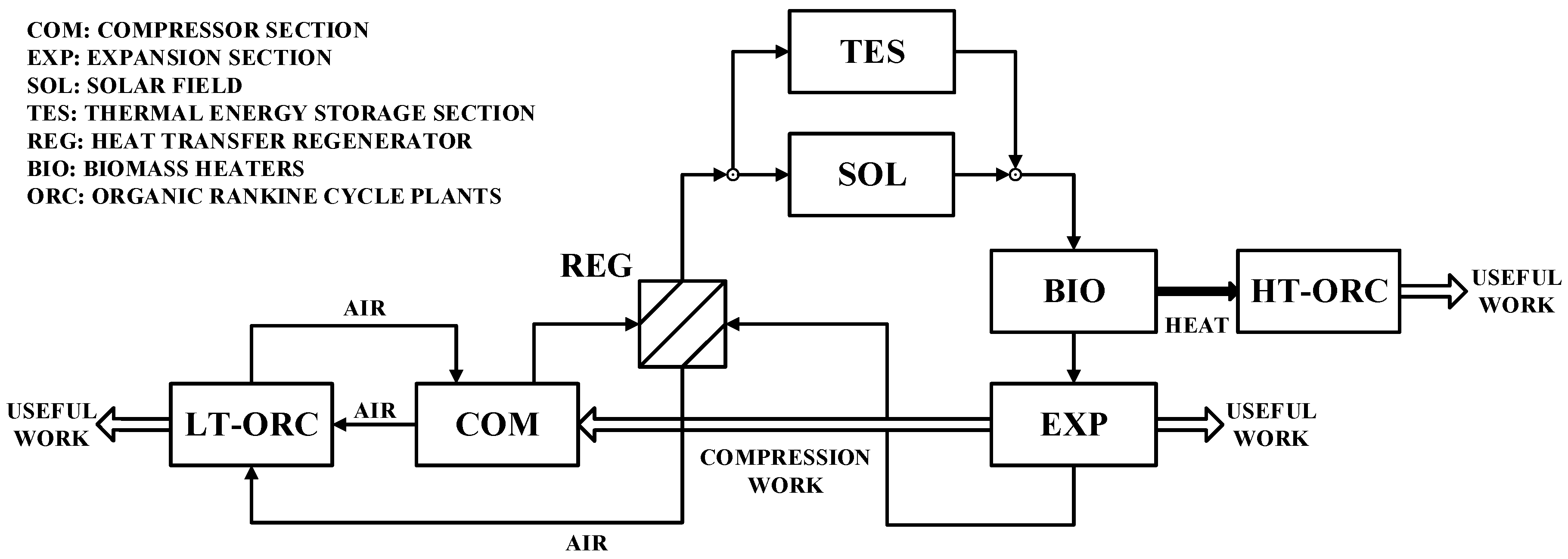
One of the downsides of the proposed plant is the thermal energy losses due to the heating and cooling needs of the HTF in the CSP-plant. In particular, these energy losses are associated with the biomass boilers (high temperature) and the intercooled compressions (low temperature). For these reasons, a further step in this study is represented by the use of Organic Rankine cycle power plants, in order to increase the overall efficiency of the whole system as well as to reduce the heat loss to the environment. With reference to the plant scheme represented in Figure 1, the available heat from the intercooled compressions, from the regenerator and from the flue gases exiting the biomass boilers are considered and the mathematical models are explained in Section 3.4.

3. Mathematical Models

3.1. Solar Receiver Model

The solar receiver represents the most important element of the solar power plant that is responsible for the collection of the solar energy. It is constituted by a metallic tube enclosed inside another co-axial tube made of glass, in which the low wavelength radiation is easily absorbed. At the same time, the glass protection shows low emissivity at long wavelength at the characteristic temperatures reached by the surface during its operation. The vacuum between the co-axial tubes lower other heat-exchange mechanisms, also assuring a protection against the oxidation of the metal surface of the absorber. Bellows are used to face the different thermal expansion between glass and metal.
The equations implemented in the model of the absorber allow the evaluation of the temperature values in five different nodes, 2 for the glass surface (internal and external), 2 for the metal surface (vacuum and fluid side), and one for the heat transfer fluid. In order to simplify the problem, thermal fields are considered to be purely radial, which, however, is a good approximation of the real thermal phenomenon that happens [12,13].
The five thermal states identified above have to satisfy the following system of equations:
h f a b s , i · D i · π · ( T a b s , i     T f ) = 2 · π · k a b s , i a b s , o · ( T a b s , i T a b s , o ) l n D a b s , o D a b s , i
q ˙ s i · τ e n v · α a b s = π · D a b s , o · h a b s , o e n v , i · ( T a b s , o T e n v , i ) + σ · π · D a b s , o   ( T a b s , o 4 T e n v , i 4 ) 1 ε a b s + ( 1 ε e n v ) · D a b s , o ε e n v · D e n v , i + 2 · π · k a b s , i a b s , o · ( T a b s , i T a b s , o ) l n D a b s , o D a b s , i
π · D a b s , o · h a b s , o e n v , i · ( T a b s , o T e n v , i ) + σ · π · D a b s , o   ( T a b s , o 4 T e n v , i 4 ) 1 ε a b s + ( 1 ε e n v ) · D a b s , o ε e n v · D e n v , i = 2 · π · k e n v ·   ( T e n v , i   T e n v , o ) l n ( D e n v , o D e n v , i )
2 · π · k e n v ·   ( T e n v , i   T e n v , o ) l n ( D e n v , o D e n v , i ) + q ˙ s i · α e n v = h e n v , o a m b · D e n v , o · π   · ( T e n v , o     T a m b ) + σ · π · D e n v , o · ε e n v · ( T e n v , o 4 T s k y 4 )
q ˙ h e a t   l o s s = h e n v , o a m b · D e n v , o · π   · ( T e n v , o     T a m b ) + σ · π · D e n v , o · ε e n v · ( T e n v , o 4 T s k y 4 )
In addition, in order to evaluate the temperature variations along the longitudinal dimension of the receiver, a 1-D model was developed to discretize the total length of the tube into n elements. For each portion of the receiver, temperatures and thermal powers exchanged are found according to the energy conservation equation, expressed as Equation (2). For this evaluation, the nodes related to the metal surface were condensed in one, considering a mean value of temperature between the inside and the outside surface:
q ˙ s i = H · cos θ · η e n v · A p = h · π · D i · [ T a b s ( x ) T f ( x ) ] [ π ( D o 2 D i 2 ) 4 d 2 ( k a b s · T a b s ) d x 2 ]
where η e n v is the effective optical efficiency at the glass envelope, expressed in Equation (3):
η e n v = ε 1 ε 2 ε 3 ε 4 ε 5 ε 6 ρ c l K
It depends on the estimated terms in Table 3:
However, it is worth noting that the processes/phenomena were not considered in this model, since they were deemed to be of secondary importance:
  • Thermal behavior of the connecting elements and sealing systems are neglected due to their much shorter dimensions with respect to the receiver. This hypothesis applies only to the connecting elements between parabolas, whose function is also to allow the mutual rotation of different strings of parabolas to allow their optimum angular positioning. The length of the strings, in fact, are of the order of hundred/thousands of meters, while the carefully insulated connecting elements are of the order of dozens of meters;
  • No temperature gradient along the circumference of the tube is considered. In fact, even if the solar irradiation incises a specific angular interval, the high thermal conductivity of the metal tends to have uniform circumferential temperature. This is also favored by the high heat transfer coefficient of the HTF, with the inner metal surfaces of the receiver.
  • The stratification of the fluid is neglected since turbulence inside the tubes allows us to reduce the thermal gradients inside them. In this case, the high Reynolds number of the HTF caused by the high air speed and density also favors a fast mixing of the fluid.
It is clear that for specific local analyses, a deeper approach could be considered by removing a part of the hypotheses mentioned before, but for a good level of modeling aimed at designing the plant, these appear to be quite acceptable. Moreover, devices exist that can further support hypotheses 2 and 3.
Among the different possibilities related to the use of a gas as heat transfer fluid, air was considered the best solution considering its availability, low cost, high safety, and good performances, potentially also allowing an open circuit plant [16]. Another important parameter is represented by the pressure drop inside the metal tubes. It can be evaluated as follows, once the collector geometry, solar radiation, initial temperature, pressure, and speed of the fluid is known:
Δ p = ψ L D ρ v 2 2 = ψ 8 L m ˙ 2 π 2 D 2 ρ
Considering the temperature dependency of the density and speed, Equation (4) could be simplified to:
Δ p = p i ± p i 2 4 A ( T T a m b ) 1.1 2
where A is a coefficient, product of terms expressed in Equation (6):
A = 0.184 · P r 0.6 · 2 2.6 · π 1.8 · D 4.8 · L · μ 0 0.2 · ρ 0 1 · p 0 · m ˙ 1.8

3.2. Plant Layout Scheme

The proposal to consider air as HTF offers the possibility of revising the conventional CSP plant layout, in order to simplify and optimize it from a technological point of view with efficiency standards close to the conventional thermoelectric conversion, which represents the actual technology.
The plant layout is reported in Figure 1. Air is compressed through a series of intercooled compressors and then heated in the solar fields. Auxiliary biomass boilers are used to reach the maximum temperature of the cycle before each expansion stage. After the last expansion stage, the high temperature heat available at the turbine outlet is partially recovered in a recuperative heat exchanger, in order to increase the temperature of the air before entering the solar receivers and increasing the plant efficiency.
Once the input data of the receiver model (described in Section 3.1) is defined, the length of the solar field can be calculated so that a fixed temperature of the air at its outlet can be reached. Inlet fluid speed is calculated on the basis of the fixed air mass flow rate, air thermodynamic parameters (pressure and temperature), and receiver geometry. However, fluid speed inside the receiver tends to increase because of pressure drop and temperature rise, due to irradiation. For this reason, a maximum allowable fluid speed was fixed in order to limit pressure losses, noise, and vibration. When this condition happens, an additional receiver in parallel with respect to the previous one is considered, splitting the flowrate and consequently reducing the fluid speed inside the receivers.
Another important aspect to consider is related to the maximum temperature values of the air, going through the solar field. In fact, higher fluid temperatures correspond to the lower efficiency of the receiver, where the losses are proportional to the metal temperature. Moreover, mechanical characteristics of the metal are not guaranteed above 580 °C, even if little variations are tolerated. By fixing all of these parameters, the model allows the design of the solar receiver to be in terms of length and number of parallels. Optimal sizing is obtained, considering the efficiency of the receiver (ηtherm), as well as the thermodynamic efficiency of the cycle and that of the whole system (ηdec) [17].
η t h e r m = Q i n _ c o l l Q s o l
η c y c l e = L e x p L c o m p r Q i n c o l l + Q i n b o i l
η D E C = L e x p L c o m p r Q s o l + Q i n b o i l η b o i l
In order to increase cycle specific work and efficiencies, our focus is on the optimum number of compressions and expansions—when it changes, pressure levels also change, requiring a series of reheating processes that operate in parallel, thus increasing the overall solar receiver length and thermal efficiency. Finally, optimization is achieved by adopting the collector length per unit power (P/L ratio) as a design parameter. In fact, it is the main parameter that mostly affects investment costs.
Thanks to this setup, the valued overall plant efficiency was close, and even greater than that of the existing technologies (thermoelectric CSP plants), despite their greater simplicity, which results in cost reduction and increase of reliability. An already optimized system layout (whose characteristics are described in Section 4) shows the number of compressions, expansions and, consequently, the number of solar fields and strings used. The image relating to the plant scheme also shows an energy storage system and exchangers designed to recover heat through small ORC plants, whose descriptions and models are reported in the following paragraphs.

3.3. Thermal Storage Section

The intermittent nature of the solar source determines the need of a thermal energy storage system that is capable of extending the operating range of this kind of power plant and helping it during characteristic transient operations. In this way, the CSP system can partially work during night time and potentially speed up the start-up phases [18,19].
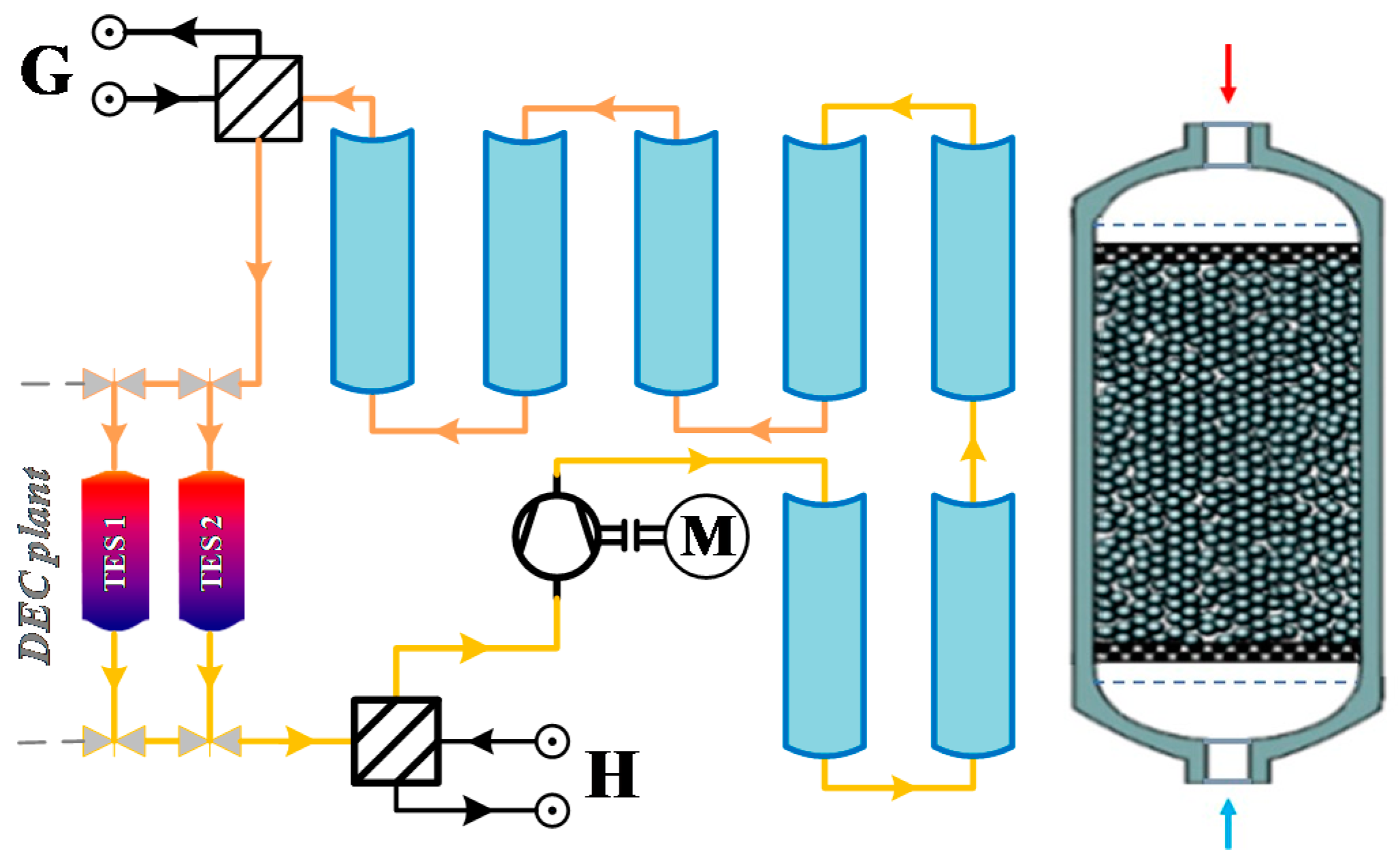
Many different technologies were studied in order to test this issue [20,21,22]. However, in the present study, a packed bed storage system was considered. In this kind of technology, a high specific heat solid in a thermally insulated tank constitutes the porous media. The solid phase is organized in spheroidal rocks whose size and quantity depends on the desired thermal characteristic of the storage system and directly influences the dimension of the tank. These rocks have the capability to store thermal energy exchange, with a heat transfer fluid, releasing it when needed.
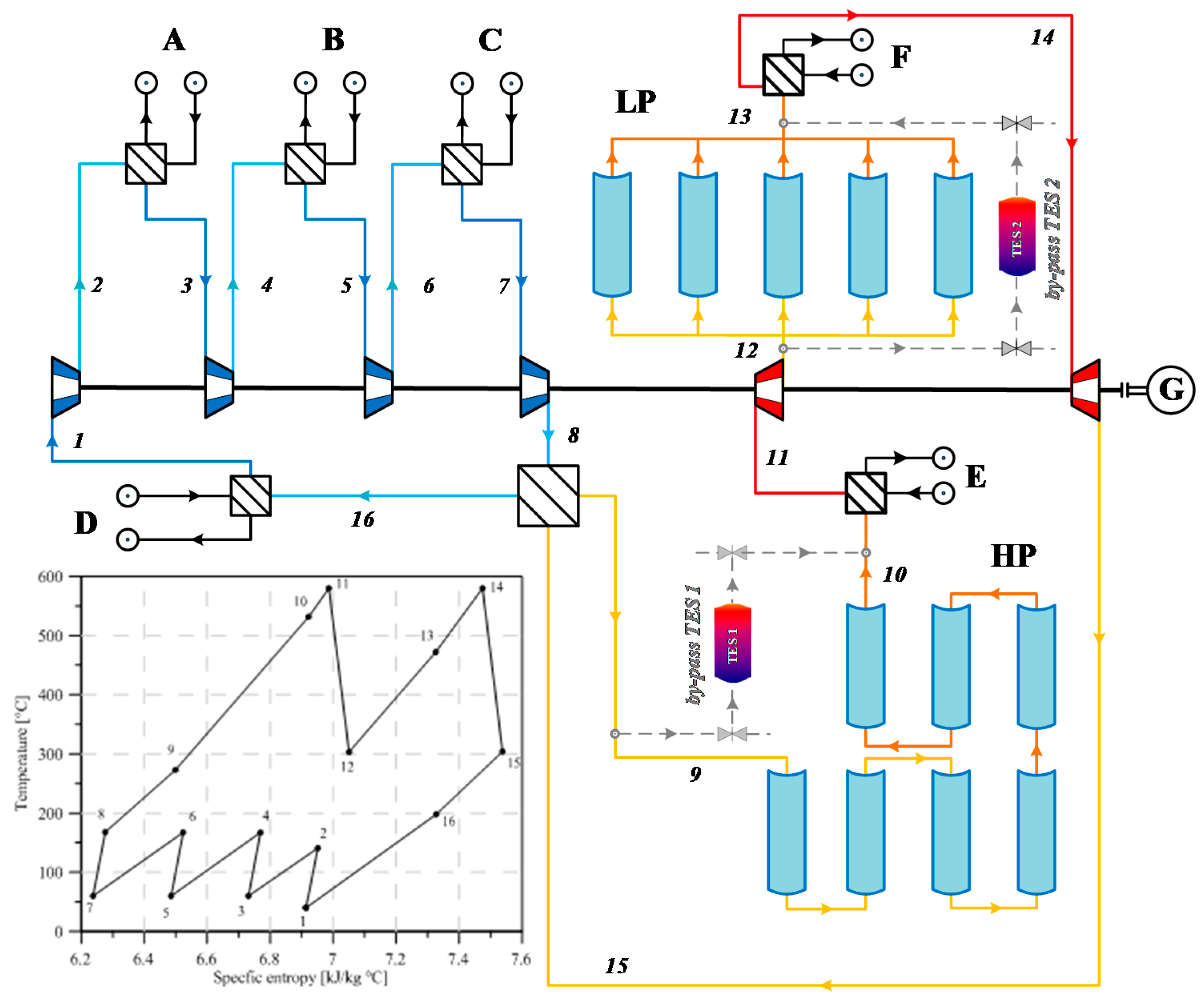
In this case, alumina rocks were considered. The storage system layout is presented in Figure 2. Two different tanks were used, one for replacing each CSP solar field, respectively, for the 9–10 and 12–13 cycle sections, Figure 5. During the charging phase, the air exiting the compressor was heated by a dedicated solar field at the same pressure. An additional heat exchanger fed by the exhaust gases of a biomass boiler was used to make the air reach the desired temperature, before passing through the porous medium from top to bottom. A second heat exchanger at the tank exit reestablished the initial temperature, upstream of the compressor, to keep low the compression work. Once charged, the tank could be connected to the DEC plant, with the compressed air moving in the opposite direction, in order to exchange heat with the rocks at higher temperature, along the flow path, and therefore, with access and in the reverse direction to the charging phase.
The main advantages of such a system are related to the possibility to set the desired maximum and minimum temperatures of the thermocline in the tank using an HTF, which did not present issues of safety and had a relatively cheap porous medium. The main downside is the compression work needed to overcome the pressure drop in the tank, ensuring the desired air flowrate.
A model based on the Shuman equations was implemented and validated, to correctly design the storage system [23]. In order to reduce the computational efforts without compromising the accuracy of the results, some assumptions were made:
  • HTF and solid phase temperatures are functions of time and the longitudinal dimension of the tank in a 1-D model. 1-D models are a usual assumption on the sector, considering that the height of the storage systems is greater than its diameter, and form a physical point of view, the traveling periods of the HTF inside them (during charging and discharging) are long enough to realize a temperature uniformity.
  • The packed bed is uniform and isotropic, considering the high filling coefficient of the concrete materials inside the storage systems—particles, in fact, that have dimensions (diameter) in the order of millimeters, and this favors a strong reduction of voids.
  • The Biot number of the spheroidal rocks is sufficiently low to consider a uniform distribution of temperature in each element. This hypothesis is further supported by the high surface to volume ratio of the elementary spheroidal rocks, which enhance the heat transfer with respect to the heat and, thus, a uniform temperature.
  • The main heat transfer mechanism is forced convection, since the contact surface area between the spheroidal elements is too small to transfer heat by conduction. Thus, the main transfer phenomenon is forced convection between HTF and concrete particles. Moreover, heat transferred by radiation and natural convection (between fluid and concrete particles) is considered to be negligible for the reduced temperature difference between mediums (radiation) with respect to forced convection (natural convection).
  • Thermal losses to the environment are neglected, since the tank is thermally insulated, in order to amplify thermal exchange between the HTF and concrete materials. A small heat transfer loss could be considered (few points percent). The results would be a slightly longer charging time and a slightly shorter discharging time; both effects could be recovered at a finer design stage.
The above assumptions, despite ignoring some phenomena that can affect the storage system performances, were made, in order to study and understand the capability of the whole plant rather than focus on the accurate description of each specific subsystem.
Given these simplifications, the governing equations of the system are represented by the energy conservation equations written below:
{ T f t · ρ f · c v · ε + T f x · G · c p = 2 T f x 2 · k e f f + h · α · ( T b T f ) T b t · ρ a l · c a l · ( 1 ε ) = h · α · ( T f T b )
The two equations represent the energy balances for the HTF and the solid phase, respectively. cv and cp are the specific heat at constant volume and pressure, respectively, while ρ represents the density and G is the air mass velocity. ε is the void fraction defined as the ratio between the volume occupied by the fluid and total control volume, to take into account the presence of the solid phase inside the tank. It also defines the effective thermal conductivity, which is the product between ε and the thermal conductivity of the gas. Regarding the heat exchange coefficient h, the Wakao correlation [24], was found to be the most appropriate:
h   = k f d ( 2 + 1.1 · P r 1 3 + R e p 0.6 )
where Pr is the Prandtl number of the fluid and Rep is the Reynolds number, referred to as the Alumina sphere diameter. α is a correction parameter defined in [25], as the ratio between the total surface of the alumina elements and the total volume. Considering the geometrical characteristics of the rocks, this could be written as:
α = 6 · ( 1 ε ) d
In the second equation of the system, which describes the energy balance of the solid phase, the same parameters appear. However, in this case, no convective term is needed, since there is no transport of the solid elements through the control volume.
The elaborated model ensures the determination of the main thermodynamic parameters (e.g., rocks and air temperature, accumulated energy) during the charging and discharging phases, at any time. Additionally, in order to define the best design parameters of the tank (spherical particle diameter, aspect ratio, air mass flow) and maximize efficiency and appropriate time of charging and discharging, a sensitivity analysis was done, whose specific characteristics are defined in Section 4.

3.4. Organic Rankine Cycle (ORC) Recovery System

The CSP layout shows efficiency improvement possibilities related to the recovery of the thermal energy wasted in the environment [26,27]. Among the available heat, two temperature levels could be distinguished. A low temperature waste heat in the inter-refrigerated compressions and at the regenerator low-pressure outlet, and a higher temperature waste heat available at the biomass boiler outlet, after the heating of the compressed air before the turbine inlet. For these reasons, two different ORC architectures were conceived, in order to have a better conversion efficiency. The Low Temperature (LT–ORC), which makes use of the air at the compressors’ and regenerator outlet as a hot source, and the High Temperature (HT–ORC), which recovers heat from the biomass boilers exhaust gases. Given the different nature of the sources, two different modeling approaches were used, in order to evaluate the performances of the two systems [28].

3.4.1. LT–ORC

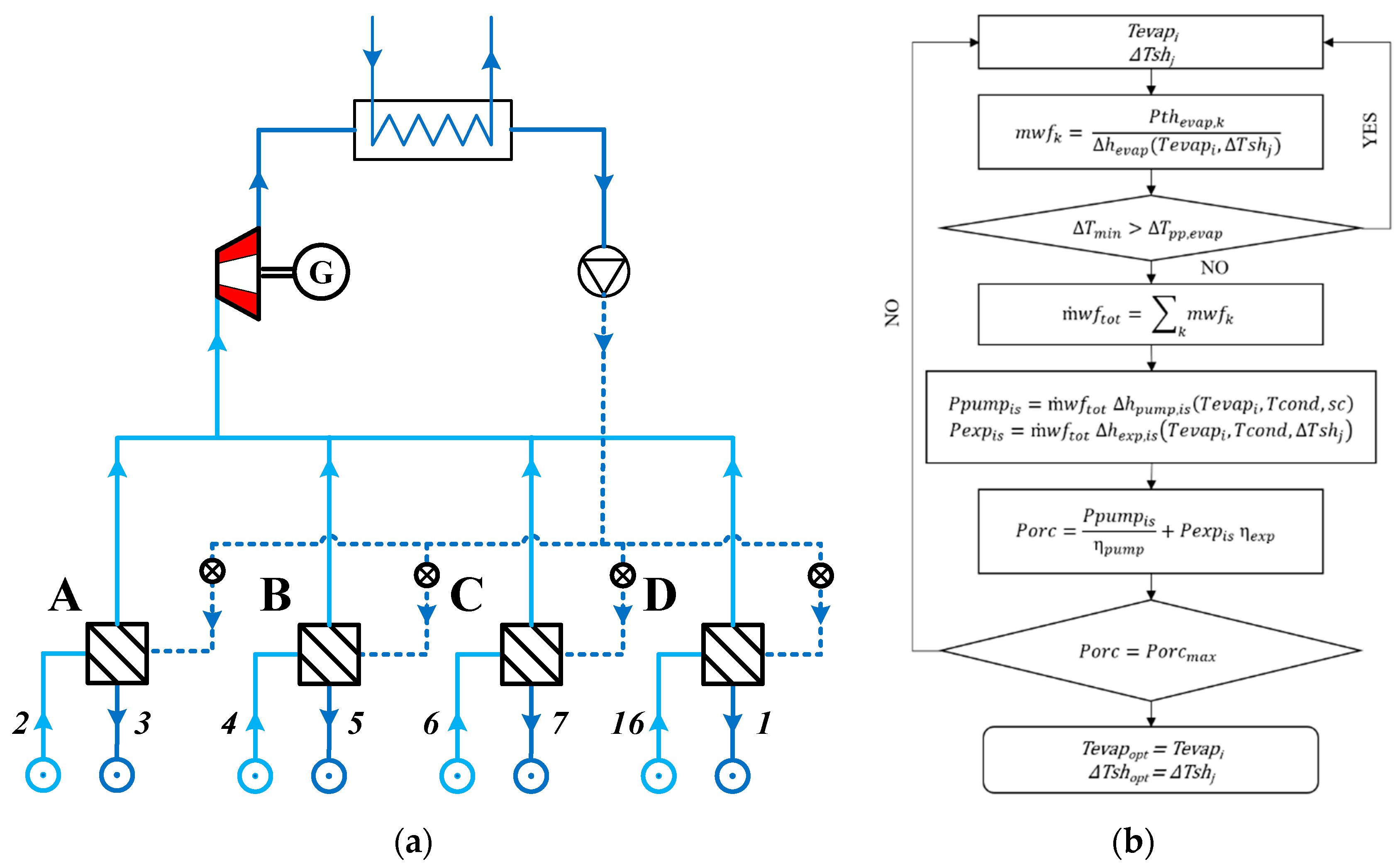
The proposed plant layout of the LT–ORC is presented in Figure 3. The heat exchangers between the compressors, and the one adopted at the regenerator outlet in the low-pressure side in order to lower the temperature down to the initial one, were substituted by 4 evaporators. No intermediate fluid was used, since it would have further lowered the hot source temperature reducing the ORC system efficiency. The organic fluid exiting the pump is split in 4 different mass flowrates, according to the available thermal power, in order to achieve the same thermodynamic conditions.
Once vaporized and superheated, in each evaporator the working fluid is collected before entering the expander and finally condensed and subcooled in the condenser, using water as a cold source. An optimization procedure described in [29] was developed, in order to evaluate the best design conditions of the ORC unit. The following simplifying assumptions were made:
  • No pressure drops in the heat exchanger: This assumption could be significantly supported by the fact that the minimization of the pressure losses inside a heat exchanger is a typical design goal, and that its length, (even if they are cumulative considered) with respect to the length of piping, is negligible;
  • Constant expander and pump efficiency with respect to operating conditions: These efficiencies depend mainly on the speed of rotation and on the mass flow rate of the working fluid. Both quantities are kept constant during usual operation, in order to maximize the recovery.
  • Thermal losses to the environment were neglected, considering that all components were carefully insulated.
Moreover, given the nature of the CSP plant in the low temperature region, the thermodynamic conditions of the hot source did not vary with the irradiation. Thus, a steady state model was considered.
The adopted optimization procedure is described in the flowchart presented in Figure 3. During the process, the evaporation temperature and the superheating degree were varied, keeping all other parameters like the condensation temperature, the subcooling degree, and the hot source inlet and outlet temperatures constant.
For each couple of values of evaporation temperature, Tevapi and superheating degree ΔThj, the working fluid mass flowrate in the evaporators (mwfk) was evaluated as follows:
m ˙ w f k = P t h e v a p , k Δ h e v a p ( T e v a p i , Δ T s h j )
where Pthevap,k is the available thermal power in the evaporator, ΔHevap is the enthalpy increase and k is the index of the heat exchanger. Once defined, the mass flowrate, the heat exchange diagram, can be evaluated together with the minimum temperature difference. If the latter (ΔTmin) is lower than the defined pinch-point temperature difference, then another couple of parameters Tevapi and ΔTshj is considered. If the relation is satisfied, the total mass flowrate entering the expander is evaluated, allowing the calculation of pump, expander, and ORC power, as:
P p u m p = m ˙ w f t o t   Δ h p u m p , i s   ( T e v a p i ,   T c o n d ,   s c ) η p u m p , i s   η p u m p , m
P e x p = m ˙ w f t o t   Δ h e x p ,   i s   ( T e v a p i ,   T c o n d ,   Δ T s h j )   η e x p , i s   η e x p , m
P O R C =   P e x p   P p u m p
where Δh represents the enthalpy change, Tcond is the condensation temperature, and sc is the subcooling degree. The optimization procedure stops when the maximum obtainable ORC power is achieved, thus defining the optimized evaporation temperature (Tevapopt) and superheating degree (ΔTshopt).

3.4.2. HT–ORC

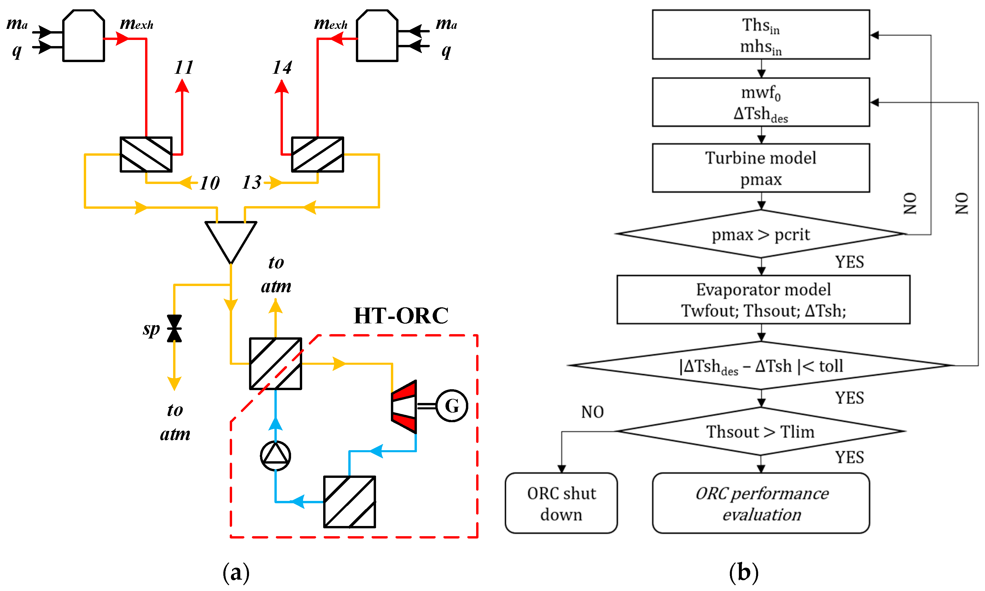
The HT–ORC recovers the mid-temperature heat available from the exhaust gases of the biomass boiler. Considering the plant layout reported in Figure 4, the flue gases coming out of the biomass boilers pass through the heat exchangers of the CSP plant, in order to raise the temperature of the compressed air up to the design value. However, the exhaust at the heat exchangers outlet still have a considerable amount of thermal energy to be recovered, before it is wasted in the environment.
As is known, the amount of this heat is strongly variable with the irradiation, producing variations of the exhaust gases, both in terms of temperature and the mass flowrate. In order to overcome this issue, a different approach was used to define the best design solution, taking into account the transient hot source. In particular, a quasi-stationary model was used to describe the behavior of the evaporator and the expander. This kind of modeling approaches are largely used when the hot source does not vary quickly and the system is able to follow its variations [30,31]. The condensation temperature and the subcooling degree were maintained, fixed at the design point. Variations of these parameters could be balanced, acting on the cold source flowrate. Moreover, this choice allowed not to model the condenser considerably, consequently reducing the computational effort.
In the first place, a design optimization at a fixed condition of the hot source was carried out using the same procedure described above in the LT–ORC section. Once all values of the design parameters are known, the evaluation of the HT–ORC performances for a different condition of the heat source, can be carried out.
The evaporator model can be described by the following equation:
U A O D = U A D ( m h s O D m h s D ) 0.8 ( ( T h s i n + T h s o u t ) O D ( T h s i n + T h s o u t ) D ) 0.8
where UA represents the product of the overall heat transfer coefficient and the heat transfer area of the evaporator, mhs is the heat source mass flowrate, and Ths is the heat source temperature. The subscripts od and d stands for off-design and design, respectively. The above equation implicitly attributes the off-design performances of the heat exchanger to the variations of the heat source conditions only. This approach is justified by the great difference in the heat exchange coefficient of an organic fluid during phase change, and a gas that can be higher than an order of magnitude.
Regarding the expander, given the higher power involved with respect to the LT–ORC, the use of an axial turbine is a right choice. It was modeled through the Stodola equation, corrected to also take into account the influence of the inlet temperature, as follows:
λ D = p m a x D 2 p m i n D 2 T t i n D
k p =   m ˙ w f D λ D
where pmax and pmin are the maximum and minimum pressures and Ttin is the turbine inlet temperature. Once known, the value of λd the parameter kp could be evaluated. Using the same kp, it is possible to calculate the value of λ for different working fluid mass flowrate, thus defining the correlation between mwf and pmax. As a result of the nonlinear equations and the dependence among them, iterations are needed in order to find the solutions for a given heat source mass flowrate and inlet temperature.
Making reference to the flowchart in Figure 4 for the heat source mass flowrate and inlet temperature (mhs and Thsin), an initial value of the working fluid mass flowrate mwf0 is assumed. The turbine model evaluates the corresponding maximum pressure pmax and the related evaporation temperature of the organic fluid. With these parameters, the subroutine of the evaporator could be run, thus finding the working fluid and hot source outlet temperatures. At this point, the working fluid superheating is compared to the desired one. If the difference is lower than a specified tolerance, the off-design thermodynamic parameters are found and the ORC performances could be evaluated. The turbine isentropic efficiency can be evaluated as:
η t , O D = η t , D ( Δ h t i s , D Δ h t i s , O D ( 2 Δ h t i s , D Δ h t i s , O D ) )
However, it is possible that when the thermal load is higher than that of the design, the working fluid mass flowrate needed to achieve a desired superheating degree determines a maximum pressure greater than the critical one. In this case, a partial bypass of the exhaust gases is needed and the iterations restart from a new working point, characterized by the same inlet temperature and a lower heat source flowrate. On the other hand, when the thermal load is much lower than that of the design, the heat source outlet temperature can drop below the acid dew point temperature Tlim. In this case, since the power output is low, the HT–ORC is shut down.

4. Plant Dimensioning and Results

4.1. Concentrated Solar Power Plant and Thermal Energy Storage Section

The system, optimized through the model described in previous sections, is represented in detail in Figure 5, together with the thermodynamic transformations in the T-s plane. Maximum temperature and pressure were fixed at 580 °C and 30 bar, respectively, together with suitable values for the minimum temperature difference in the heat exchanger and component efficiencies. These design data match the present performances of the most relevant components, like receivers and maximum metal temperature, which could be compensated by the metal bellows between the metallic and the glass hoses. Air inlet temperature at the first compressor stage was 40 °C, at atmospheric pressure. Mass flowrate was fixed at 1 kg/s. The optimization model led to the definition of 4 compression stages and 2 expansions. This choice was a compromise between the incremental advantage on the net power produced and a reasonable design choice. The net power increased with the number of compressions and expansions, but the incremental advantage became less and less significant, when the number of machines increased. On the other hand, the management of an increased number of machines become more and more complex, also increasing the costs, as a result.
Figure 5 represents the thermodynamic cycle concerning the integration between compression section, regeneration, first heating, expansion section and re-heating. These parameters are expressed in Table 4, including the absorbed heat, the produced power and the plant efficiency. These provided interesting values when compared with the existing technology for conventional CSP plants, which use oils and salts as HTF, i.e., net plant efficiency at 17.1%, (in line with 14–20% of PTC plants, [11]). The thermodynamic data reported in Figure 5 are the result of the calculation of the correspondent discrete Ericsson cycle with four optimized compressions (up to 30 bars as maximum pressure) and two expansions, assuming most relevant data (efficiencies of machines, pinch points, etc.). When a maximum temperature for the air as HTF is fixed (i.e., the thermal power that must be exchanged toward the compressed air) (thanks to the model of the solar receivers—Equations (1a–e), (2), and (3)), the overall length for each pressure level (after the compression and during the two expansions) can be calculated, increasing it till the data desired from the thermodynamic analysis is reached. In this sense, the overall modeling is used as design tool, by iterating it until the desired performances are reached.
The definition of the DEC layout and modeling and the sizing of all components, allowed us to simulate the plant electrical production and the operating conditions in a solar year, for any location, in order to quantify the different contributions (solar, biomass, TES), and potentially compare this production with that of a conventional CSP plant, using oils and salts as HTF.
The TES section is dimensioned in order to give 3 h of additional autonomy to the DEC plant, with the following parameters: 84 m solar plant with the same characteristics as that of the DEC, with a tank whose design is briefly presented in Table 5, and charging and discharging phases, quantified in [17,28]. The charge of the two tanks is exerted at the same pressure, while the discharge is done at different ones. This aspect does not influence the discharging time, which still remains the same for both tanks. The 3 h capacity is allowed, as a result of the two charged tank that operates in parallel, each for every expansion section, for 6 h of total charging phase. For each tank, outlet temperature is about 270 °C and output temperature at 550 °C. Air mass flowrate can be increased, in order to achieve a shorter charging and discharging time. However, in this case, the solar collector length would be greater due to the need for splitting the flowrate in different solar receivers operating in parallel, when the air velocity tends to exceed the maximum allowable speed. In this case, the modeling reported in Equations (8) is also used as a design tool to get the desired time period of the additional continuous autonomy. After having chosen the most relevant parameters for the thermal energy storage (see data reported in Table 5), the design found the height and the diameter of the thermal storage system, which fulfilled the two data referred to the energy accumulated (894 kWh and 815 kWh returned to the HTF).
Assuming the operation of the plant only when the solar source provides a sensible contribution (from 6.00 am to 18.00 pm) and the contribution of the TES section, the annual global energy production is evaluated for a specific location (Priolo Gargallo, in Sicily; the same location as that of the “Archimede” project, [32]).
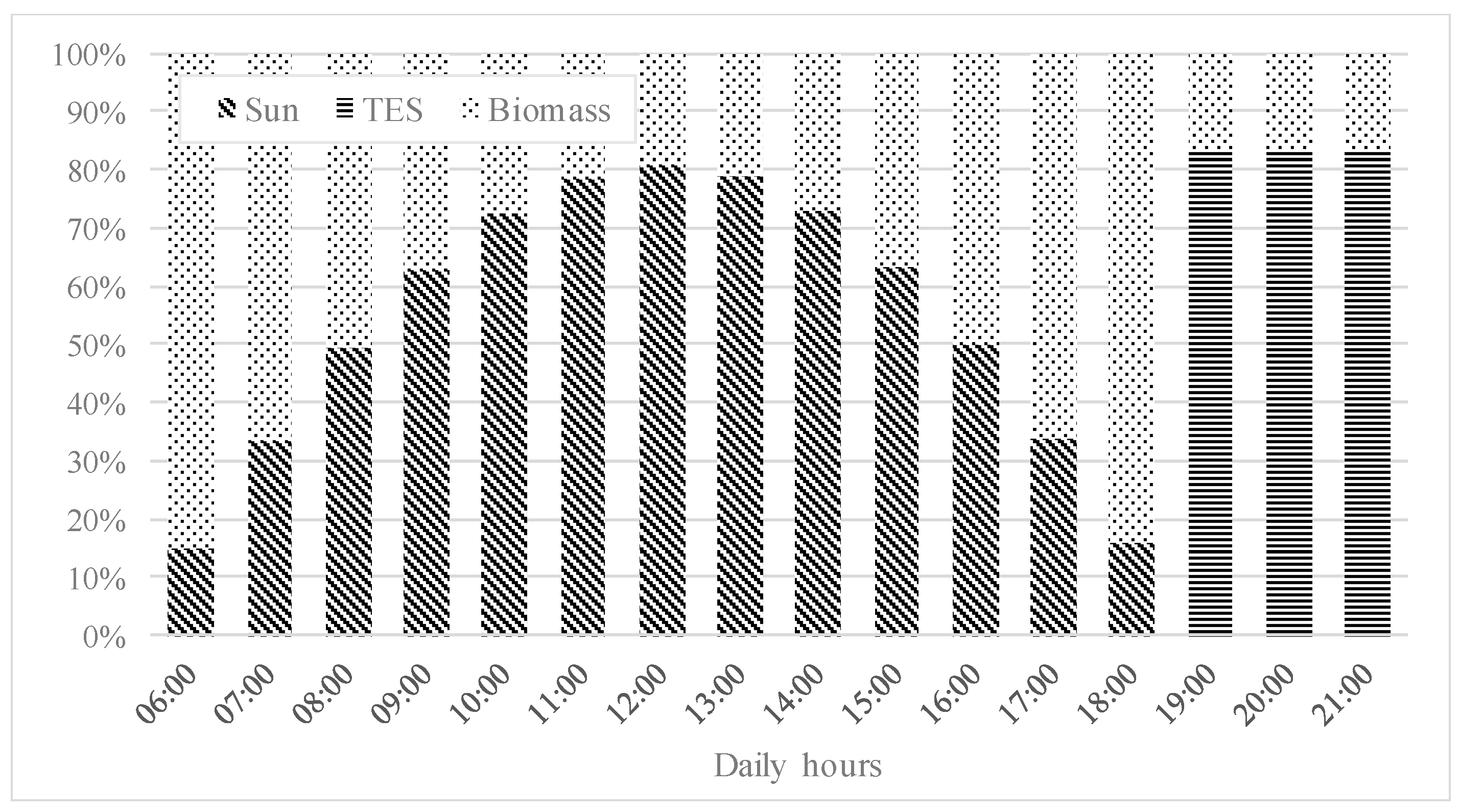
As an example, a daily percentage division of the different contributions is expressed in Figure 6, for the 21st of June, in which, for the TES section and considering the best irradiation hours, the contribution of solar field was in an order of 44.2%, with a biomass at 40.1% and a TES section of 15.7%.
The annual percentage division of the same contributions is 67.5% of the biomass contribution and 32.3% of solar one, for a global energy production of 805 MWh/y for the DEC plant and a TES contribution of about 185.8 MWh/y.
The mathematical model relating to the PTC considers the monthly average daily radiation on a surface, with a given inclination and azimuth, using the UNI 8477-1 standard, [33]. The result of the procedure returns an irradiation value extended to the period of one day and a monthly average, because the calculations refer to the day of the month, which has specific characteristics. The method is not based on the exact calculation of solar gains but on the measured values of ground radiation, of over a month, which is statistically more significant than the instantaneous values. Once the hourly irradiation factor is determined, for a given location and a given day of the year, it is possible to adapt the UNI 8477-1 standard to an hourly calculation, rather than a monthly average. To quantify the energy captured on a surface in a single day, it is necessary to consider the daily variation of extra-atmospheric radiation, the variation of the reciprocal position of the Earth–Sun and the specific meteorological conditions for that day—these steps are taken by considering the meteorological studies of Gordon and Reddy [34], and the exponential model of Aguiar and Collares-Pereira [35]. From these corrections, it is possible to obtain the direct hourly irradiation value.

4.2. Waste Heat Recovery Section

As aforementioned, the CSP plant with the storage system is able to produce a mean power of 170 kW, resulting in about 805 MWh of energy produced during the year, considering the variable radiation conditions. However, the WHR sections consisting of a low temperature, and a high temperature ORC system could increase its productivity, by utilizing the different heat sources that the CSP plant makes available.
Regarding the LT–ORC, different working fluids are considered (Table 6) in the study, taking into account the thermodynamic and environmental performances.
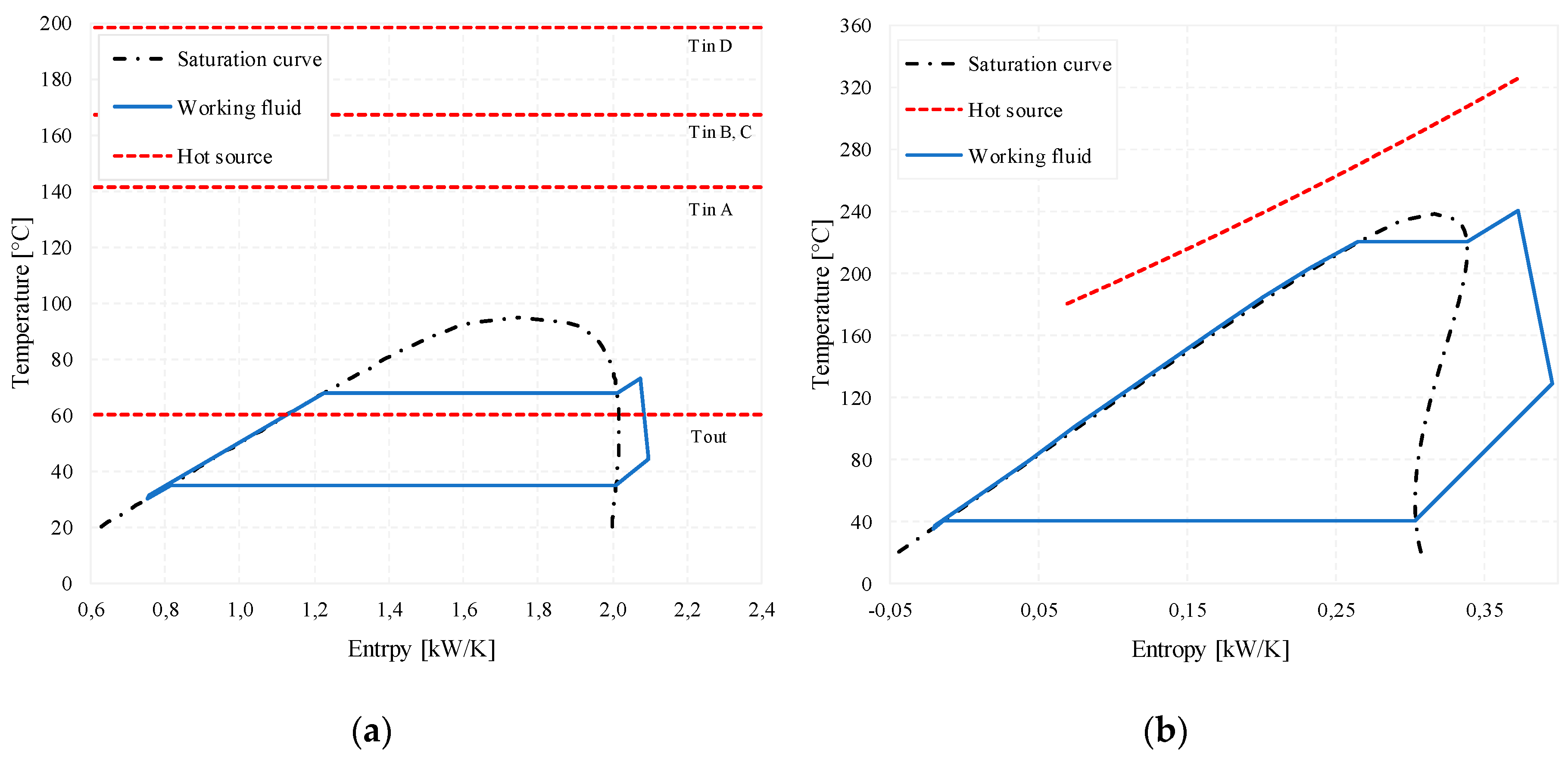
Making reference to Figure 3, the input parameter of the analysis, as well as the system constraints, are listed in Table 7. The heat source is represented by the air exiting the compressors and the regenerator at temperature Tin A, Tin B,C, and Tin D, respectively.
Best performances are achieved with R1234yf, which allows the production of 23.5 kW of output power, showing an overall plant efficiency of the LT–ORC equal to 5.4%.
The high temperature waste heat recovery section instead is characterized by higher temperature levels of the heat source, determining the need for a higher critical temperature organic fluid that can recover thermal power more efficiently. For this reason, cyclopentane is considered, which had a critical temperature of 239 °C and a critical pressure of 45 bar. Design parameters are listed in Table 7. T-s diagrams for the LT and HT–ORC at design conditions are presented in Figure 7. A different representation is chosen for the heat source in the LT–ORC, since 4 different evaporators exist in the plant layout (Figure 3). Inlet temperature and flowrate of the heat source at the design conditions correspond to the values obtained when the radiation is absent in the HT–ORC. In these conditions, in fact, much more thermal power is available because of the higher flowrate of exhaust gases needed to operate the CSP plant. The HT–ORC is able to recover 160 kW of thermal energy with an efficiency of around 20%, showing a power output equal to 30.7 kW. Table 8 resumes the different characteristics of the different sections with the single energy production for each one.
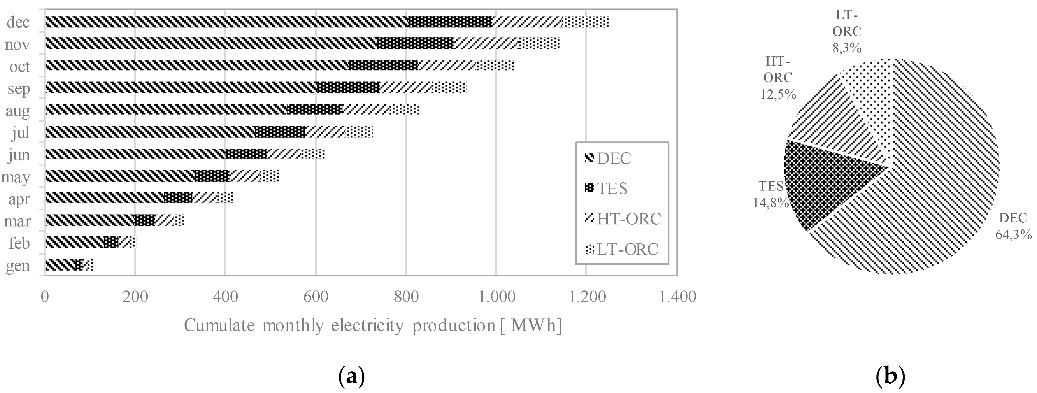
Once defined, the design parameters that influence the behavior of the system at different input conditions, on a yearly analysis, is conducted. Given the nature of the LT–ORC system, it showed a flat contribution to the energy produced over the year, which topped at 103 MWh, representing almost 8.3% of the CSP energy production; Figure 8. On the other hand, the HT–ORC system shows a variable contribution over the year. However, the chosen design point allows to limit the monthly produced energy oscillations below 20%, assuring a yearly energy production of about 157 MWh, which represents 12.5% of the CSP plant, in which, the main energy contribution is the DEC section, with 64.3% of energy production. The three-hour increase in operating hours assured by the TES system contributes to nearly 15% of the overall energy production.
5. Conclusions

A small scale 170 kW CSP-PT power plant using conventional technologies and air as heat transfer fluid was presented. Main additional components of the plant consist of a packed bed thermal energy storage, two biomass external boilers to guarantee the design conditions of the plant regardless of the available solar power, and two ORC power units operating at two different temperature levels, in order to recover heat from the intercooled compressions and the recuperative heat exchanger (LT–ORC) and from the exhaust gases of the biomass boilers (HT–ORC).
Considering a typical annual irradiation in South Italy and considering the daily operativity of the plant from 6.00 to 18.00 (and with a TES contribution for the following three hours), the system shows an annual electricity production of 991 MWh per year, with the contribution of the CSP plant being 805.3 MWh. A significant fraction of the energy production (20.8%) is due to the ORC units (260.3 MWh), where the lower operating temperature of the LT–ORC contributes for about 8.3% to this energy and the HT–ORC plant for 12.5%.

Author Contributions

Conceptualization, R.C. (Roberto Cipollone) and A.C.; methodology, R.C. (Roberto Cipollone) and A.C.; software, A.C. and M.D.B.; validation, R.C. (Roberto Cipollone), R.C. (Roberto Carapellucci) and A.C.; formal analysis, A.C. and M.D.B.; investigation, A.C. and M.D.B.; resources, R.C. (Roberto Cipollone) and A.C.; data curation, A.C. and M.D.B.; writing—original draft preparation, A.C. and M.D.B.; writing—review and editing, A.C., M.D.B., R.C. (Roberto Cipollone) and R.C. (Roberto Carapellucci); visualization, A.C.; supervision, R.C. (Roberto Cipollone); project administration, R.C. (Roberto Cipollone). All authors have read and agreed to the published version of the manuscript.

Funding

This research received no external funding.

Conflicts of Interest

The authors declare no conflict of interest.

Nomenclature

SymbolParametersSymbolParameters
Apparabolic reflector aperturevspeed
cspecific heat Wwork
Ddiameterαabsorptance
hconvection heat transfer coefficientβpressure ratio
henthalpy Δppressure drop
Kincident angle modifierεemissivity
Llengthηefficiency
mass flow rateθsolar incident angle from the normal to the projected collector area
ppressureκthermal conductance
PrPrandtl numberμdynamic viscosity
Qheatρdensity
q’heat flux per unit lengthσStefan-Boltzmann constant
ReReynolds numberτtransmittance
Ttemperatureνkinematic viscosity
SubscriptParametersSubscriptParameters
absabsorber pipeffluid
alaluminahshot source
ambatmosphereHTHigh Temperature
bbediinner
boilboilerininlet
collcollectorisisentropic
comprcompressionLTLow Temperature
condcondensation/condensermmetal/mechanical
condconduction processodoff-design
convconvention processoptoptical
critcriticalORCOrganic Rankine Cycle
CSPConcentrated Solar Poweroutoutlet
cyclecycleradradiation process
ddesignscsubcooling
decDiscrete Ericsson Cycleshsuperheating
DECDiscrete Ericsson CyclesiSolar irradiance
envglass envelopeskySky
evapevaporation/evaporatorsolsolar
expexpansionththermal
expexpanderthermthermal

References

  1. Rhodes, C.J. The 2015 Paris Climate Change Conference: COP21. Sci. Prog. 2016, 99, 97–104. [Google Scholar] [CrossRef]
  2. NOAA trends in Atmospheric Carbon Dioxide. Available online: https://www.esrl.noaa.gov/gmd/ccgg/trends/ (accessed on 14 July 2020).
  3. BP Statistical review of World Energy. Available online: https://www.bp.com/en/global/corporate/energy-economics/statistical-review-of-world-energy.html (accessed on 12 July 2020).
  4. Teske, S. Global and regional 100 percent renewable energy scenarios. In Achieving the Paris Climate Agreement Goals; Springer: Cham, Switzerland, 2019. [Google Scholar] [CrossRef] [Green Version]
  5. Weinstein, L.A.; Loomis, J.; Bhatia, B.; Bierman, D.M.; Wang, E.N.; Chen, G. Concentrating Solar Power. Chem. Rev. 2015, 115, 12797–12838. [Google Scholar] [CrossRef]
  6. Ahmed, K.A.; Natarajan, E. Numerical investigation on the effect of toroidal rings in a parabolic trough receiver with the operation of gases: An energy and exergy analysis. Energy 2020, 203, 117880. [Google Scholar] [CrossRef]
  7. Bellos, E.; Tzivanidis, C.; Daniil, I.; Antonopoulos, K.A. The impact of internal longitudinal fins in parabolic trough collectors operating with gases. Energy Convers. Manag. 2017, 135, 35–54. [Google Scholar] [CrossRef]
  8. Cipollone, R.; Cinocca, A. Integration between gas turbines and concentrated parabolic trough solar power plants. In ASME International Mechanical Engineering Congress and Exposition; American Society of Mechanical Engineers: New York, NY, USA, 2012; Volume 45226, pp. 1639–1650. [Google Scholar]
  9. Talebbeydokhti, P.; Cinocca, A.; Cipollone, R.; Morico, B. Analysis and optimization of LT-MED system powered by an innovative CSP plant. Desalination 2017, 413, 223–233. [Google Scholar] [CrossRef]
  10. Mohammadi, K.; Saghafifar, M.; Ellingwood, K.; Powell, K. Hybrid concentrated solar power (CSP)-desalination systems: A review. Desalination 2019, 468, 114083. [Google Scholar] [CrossRef]
  11. Islam, M.T.; Huda, N.; Abdullah, A.B.; Saidur, R. A comprehensive review of state-of-the-art concentrating solar power (CSP) technologies: Current status and research trends. Renew. Sustain. Energy Rev. 2018, 91, 987–1018. [Google Scholar] [CrossRef]
  12. Forristall, R. Heat Transfer Analysis and Modeling of a Parabolic Trough Solar Receiver Implemented in Engineering Equation Solver; NREL-U.S. Department of Energy Laboratory: Golden, CO, USA, 2003.
  13. Burkholder, F.; Kutscher, C. Heat Loss Testing of Schott’s 2008 PTR70 Parabolic Trough Receiver; Technical Report; National Renewable Energy Lab. (NREL): Golden, CO, USA, 2009.
  14. Rodrìguez-Garcìa, M.M.; Marquez-Payes, J.M.; Biencinto, M.; Adler, J.P.; Díez, L. First experimental results of a solar PTC facility using gas as the heat transfer fluid. In Proceedings of the 15th SolarPACES Conference, Berlin, Germany, 15–18 September 2009. [Google Scholar]
  15. Cipollone, R.; Cinocca, A.; Gualtieri, A. Gases as working fluid in parabolic trough CSP plants. Procedia Comput. Sci. 2013, 19, 702–711. [Google Scholar] [CrossRef] [Green Version]
  16. Cipollone, R.; Cinocca, A.; Gualtieri, A. A new conversion section for Parabolic Trough-Concentrated Solar Power (CSP-PT) plants. Energy Procedia 2014, 45, 61–70. [Google Scholar] [CrossRef] [Green Version]
  17. Cinocca, A.; Cipollone, R.; Carapellucci, R.; Iampieri, R.; Rivo, M. CSP-PT gas plant using air as Heat Transfer Fluid with a packed-bed storage section. Energy Procedia 2018, 148, 852–859. [Google Scholar] [CrossRef]
  18. Cascetta, M.; Cau, G.; Puddu, P.; Serra, F. Numerical investigation of a packed bed thermal energy storage system with different heat transfer fluids. Energy Procedia 2014, 45, 598–607. [Google Scholar] [CrossRef]
  19. Cascetta, M.; Serra, F.; Arena, S.; Casti, E.; Cau, G.; Puddu, P. Experimental and numerical research activity on a packed bed TES system. Energies 2016, 9, 758. [Google Scholar] [CrossRef] [Green Version]
  20. Zanganeh, G.; Pedretti, A.; Zavattoni, S.; Barbato, M.; Steinfeld, A. Packed-Bed thermal storage for concentrated solar power-Pilot-scale demonstration and industrial-scale design. Sol. Energy 2012, 86, 3084–3098. [Google Scholar] [CrossRef]
  21. Hänchen, M.; Brückner, S.; Steinfeld, A. High-Temperature thermal storage using a packed bed of rocks–heat transfer analysis and experimental validation. Appl. Therm. Eng. 2011, 31, 1798–1806. [Google Scholar] [CrossRef]
  22. Zhang, H.; Baeyens, J.; Caceres, G.; Degreve, J.; Lv, Y. Thermal energy storage: Recent developments and practical aspects. Prog. Energy Combust. Sci. 2016, 53, 1–40. [Google Scholar] [CrossRef]
  23. Schumann, T. Heat transfer: A liquid flowing through a porous prism. J. Frankl. Inst. 1929, 208, 405–416. [Google Scholar] [CrossRef]
  24. Wakao, N.; Kaguei, S.; Funazari, T. Effect of fluid dispersion coefficients on particle-to-fluid heat transfer coefficients in packed beds. Chem. Eng. Sci. 1979, 35, 325–336. [Google Scholar] [CrossRef]
  25. Dullien, F.A.L. Porous Media Fluid Transport and Pore Structure; Academic Press: New York, NY, USA, 1979. [Google Scholar]
  26. Petrollese, M.; Cocco, D.; Cau, G. Small-Scale CSP plant coupled with an ORC system for providing dispatchable power: The ottana solar facility. Energy Procedia 2017, 129, 708–715. [Google Scholar] [CrossRef]
  27. Petrollese, M.; Cau, G.; Cocco, D. The Ottana solar facility: Dispatchable power from small-scale CSP plants based on ORC systems. Renew. Energy 2020, 147 Pt 3, 2932–2943. [Google Scholar] [CrossRef]
  28. Cinocca, A.; di Bartolomeo, M.; Cipollone, R.; Carapellucci, R. A CSP plant using air as working fluid with a thermal storage section and an ORC-based energy recovery system. In AIP Conference Proceedings; AIP Publishing LLC: Melville, NY, USA, 2019; p. 020047. [Google Scholar] [CrossRef]
  29. Di Battista, D.; Cipollone, R.; Villante, C.; Fornari, C.; Mauriello, M. The potential of mixtures of pure fluids in ORC-based power units fed by exhaust gases in Internal Combustion Engines. Energy Procedia 2016, 101C, 1264–1271. [Google Scholar] [CrossRef]
  30. Imran, M.; Haglind, F.; Lemort, V.; Meroni, A. Multi-objective optimization of organic Rankine cycle power systems for waste heat recovery on heavy-duty vehicles. In Proceedings of the ECOS 2018-The 31th International Conference on Efficiency, Cost, Optimization, Simulation and Environmental Impact of Energy, Guimarães, Portugal, 17–22 June 2018. [Google Scholar]
  31. Mondejar, M.E.; Ahlgren, F.; Thern, M.; Genrup, M. Quasi-Steady state simulation of an organic Rankine cycle for waste heat recovery in a passenger vessel. Appl. Energy 2017, 185, 1324–1335. [Google Scholar] [CrossRef]
  32. Manzolini, G.; Giostri, A.; Saccilotto, C.; Silva, P.; Macchi, E. Development of an innovative code for the design of thermodynamic solar power plants part B: Performance assessment of commercial and innovative technologies. Renew. Energy 2011, 36, 2465–2473. [Google Scholar] [CrossRef]
  33. UNI 8477-1:1983. Energia Solare—Calcolo Degli Apporti per Applicazioni in Edilizia—Valutazione Dell’energia Raggiante Ricevuta; Ente Nazionale Italiano di Unificazione: Milan, Italy, 1983. [Google Scholar]
  34. Gordon, J.M.; Reddy, T.A. Stationary Statistics and Sequential Properties of Normal Beam Solar Radiation on Tilted Surfaces. Sol. Energy 1989, 42, 35–44. [Google Scholar] [CrossRef]
  35. Aguiar, R.; Collares-Pereira, M. Statistical properties of hourly global radiation. Solar Energy 1992, 48, 157–167. [Google Scholar] [CrossRef]
Figure 1. Schematic plant layout.
Energies 13 04741 g001
Figure 2. Thermal energy storage layout and tank fluxes representation.
Energies 13 04741 g002
Figure 3. LT–ORC layout (a) and optimization algorithm flowchart (b).
Energies 13 04741 g003
Figure 4. HT–ORC and bottoming system layout (a) and off-design (b).
Energies 13 04741 g004
Figure 5. Discrete Ericsson Cycle (DEC) plant layout and T-s cycle.
Energies 13 04741 g005
Figure 6. Hourly percentage division of the solar, biomass, and TES contribution for the 21st of June.
Energies 13 04741 g006
Figure 7. Temperature—Entropy diagram of LT–ORC (a) and HT–ORC (b) at design conditions.
Energies 13 04741 g007
Figure 8. Cumulate monthly electricity production for each plant section (a) and percentage annual distribution (b).
Energies 13 04741 g008
Table 1. Geometrical data of the Heat Collector Element (HCE) [12].
Parabolic Focus f 1.61m
Parabolic reflector aperture A p 2.88m
Outer envelope diameter D e n v , o 0.070m
Inner envelope diameter D e n v , i 0.064m
Outer absorber diameter D a b s , o 0.114m
Inner absorber diameter D a b s , i 0.108m
Focus axis deviation d −0.030m
Table 2. Comparison between Heat Transfer Fluid (HTF).
HTFToxicityFlammabilityCorrosivityStability Limit
Therminol VP1ToxicFlash point (110 °C)Copper corrosive<400 °C
Dowtherm QToxicFlash point (120 °C)Non corrosive<400 °C
Hitec XLNon toxicNon flammableLow Corrosivity<550 °C
HeNon toxicNon flammableNon corrosive>550 °C
CO2Non toxicNon flammableNon corrosive>550 °C
AirNon toxicNon flammableNon corrosive>550 °C
ArNon toxicNon flammableNon corrosive>550 °C
N2Non toxicNon flammableNon corrosive>550 °C
Table 3. Estimates of optical efficiency terms [13].
Terms Terms ExplicationValue
ε 1 HCE Shadowing (bellows, supports)0.974
ε 2 Tracking Error0.994
ε 3 Geometry Error (mirror alignment)0.980
ε 4 Dirt on Mirrors0.965
ε 5 Dirt on HCE0.982
ε 6 Unaccounted0.960
ρ c l Clean Mirror Reflectance0.935
Table 4. DEC-based plant parameters.
ParameterValueUnit
Temperature levels40–580°C
Pressure levels1–30bar
Mass flow rate1kg/s
Pinch point at the inter-cooling heat exchanger Δ T p p ,   c o o l 20 °C
Pinch point at the regenerator Δ T p p ,   r e g e n 30 °C
Compressor (adiabatic) efficiency η c o m p 0.85
Turbine (adiabatic) efficiency η t u r b 0.89
Collector length12m
Number of collector modules12-
SF total length144m
Number of compressions4-
Number of expansions2-
Plant power170kW
Cycle efficiency26.9%
DEC efficiency17.1%
Solar share75.2%
Biomass boiler efficiency70%
P/L ratio1175kW/m
Table 5. Storage section parameters.
ParameterValue
Mass flow rate (m)1 kg/s
Tank inlet temperature (Tmax)550 °C
Tank outlet temperature (Tmin)270 °C
Pressure (p)30 bars
Diameter tank (D)2 m
Tank height (H)3 m
Diameter of Alumina rocks (d)4 mm
Void Fraction (ε)0.39
Charging time for each tank (Tch)3 h
Discharging time for each tank (Tdis)3 h
Energy accumulated (Estore)894 kWht
Energy returned in discharge (Eout)815 kWht
Table 6. Working fluids properties and performances of the LT–ORC.
Working FluidCritical Temperature [°C]Critical Pressure [bar]GWPPower Output [kW]
R1234yf94.733.8423.5
R1234ze109.436.4617.2
R1233zdE166.536.2112.3
Table 7. LT–ORC and HT–ORC parameters.
LT–ORC
ParameterValueUnit
Tin A141°C
Tin B, C167.2°C
Tin D198°C
Tout A, B, C, D60°C
mhs1kg/s
Tcond35°C
Tcsin20°C
DTpp, evap, min20°C
HT–ORC
ParameterValueUnit
Working fluidcyclopen-
Tcond40°C
DTsc5°C
pmin0.74bar
pmax,d35.4bar
Tevap,d220°C
DTsh,d20°C
mhs,d1.06kg/s
Table 8. Expected plant performances.
ParameterValueUnit
CSP energy production805.3MWh/y
CSP solar energy share32.5%
CSP biomass energy share67.5%
Biomass consumption930ton/y
TES energy production185.6MWh/y
Mean HT–ORC power level30.7kW
Mean HT–ORC efficiency18.3%
HT–ORC power production156.9MWh/y
HT–ORC running time4228h/y
LT–ORC power level23.5kW
LT–ORC efficiency5.3%
LT–ORC power production103.4MWh/y
HT–ORC running time4380h/y