Abstract
The article offers a systematic approach to the method of developing mathematical models of a chemical-technological system (CTS) in conditions of deficit and fuzziness of initial information using available data of various types. Based on the results of research and processing of the collected quantitative and qualitative information, mathematical models of the reactor are constructed. Formalized and obtained mathematical statements of the control problem for choosing effective modes of operation of technological systems are based on mathematical modeling. Based on the obtained expert information, linguistic variables were described and a database of rules describing the operation of the input parameters of the reactor unit of the catalytic cracking unit was obtained.
1. Introduction
Catalytic cracking is the most important process in refining oil to produce gasoline. The catalytic cracking unit is designed for processing vacuum distillate to produce a component of high-octane gasoline. The results of catalytic cracking are generally determined by such indicators as the of conversion raw materials, the yield of target products and their quality.
The cracking reaction is mainly represented by a break in the “carbon-carbon” bond, which refers to an endothermic reaction—the higher the temperature, the higher the reaction rate. The cracking reaction is one of the most important types of reactions in the process of catalytic cracking. The higher molecular weight of hydrocarbon in the homological series, the higher the reaction rate. Catalytic cracking is a process whose technological mode depends on the characteristics of raw materials and catalysts, atmospheric air, etc., not all of which can be measured or measured in the laboratory, which requires the experience of experts in control systems. A technological process is subject to strict restrictions on the ranges of temperature, concentration and pressure values in the reactor unit apparatus. One of the ways to use the experience of operational personnel is to use the mathematical apparatus of fuzzy set theory for algorithmization of control problems. For effective research and optimization of processes and units of oil refining, it is necessary to build their mathematical models that take into account the nature and state of the process, the type and other features of objects [1,2,3,4].
Ultra-high-silica ZSM-5 zeolites are now most commonly used. An important feature of the zeolite structure is the presence of a three-dimensional anion framework constructed from SiO and AlO tetrahedra interconnected by strong Si-O-Si and Si-O-Al bridges. This creates a system of intracrystalline pores and cavities, where occlusion and molecule formation of the appropriate size can easily occur. The presence of pores and cavities in the framework of anhydrous zeolite is associated with important molecular sieve properties of zeolites—the ability to selectively adsorb and desorb molecules of certain sizes. Among the most important properties of zeolites with respect to their use as catalysts is their application as solid acids. The acid-base character of the catalytic surface is due to the presence of Lewis and Brønsted acid sites (Figure 1) [5].
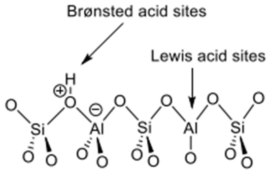
Figure 1.
Brønsted and Lewis acid sites in zeolites [5].
Zeolites also contain aprotic or Lewis acid centers with electron-acceptor properties (Figure 1). These include various coordination-unsaturated atoms or lattice ions that have a vacant p-orbital, as well as exchange cations with a positive charge. When hydrogen forms of zeolites are dehydroxylated, AlO tetrahedra are formed, devoid of a proton that compensates for their charge, which have the properties of Lewis bases. ZSM-5 increased the electrophilicity of the metal and therefore increased the oxidation stage in the catalytic cycle during the CPOM reaction, increasing the reaction rate accordingly [6].
When developing mathematical models in order to solve problems related to control of operating modes of actual chemical/technological systems (CTS), fuzziness problems associated with lack and fuzziness of initial information often occur. The most effective way to solve such fuzziness problems is to use systematic approach based on availability of various information [7,8]. Methods of system analysis play a significant role in designing and improvement of complex systems and process control [9]. However, these methods can not be applied if uncertainty is combined with fuzziness of initial information and this is often the case in the real working conditions. In these conditions statistical information is either not available or insufficient under such conditions and probability theory axioms (statistical stability of researched object, repeatability of experiments under identical conditions) are not performed. Available information is sometimes uncertain that is person’s (person making decisions—PMD, expert) knowledge (experience, intuition, judgment). Effective formalization of uncertain information representing knowledge of experts on CES may be obtained based on methods for expert evaluations and fuzzy set theory (FST) [10,11,12,13].
If PMDs, experts are competent and there is proper organization for their questioning, collecting and processing of uncertain information, models can be built that include all complex interrelations with various parameters and variable complex CES. Such models can be more informative than those developed via traditional methods plus they may accurately describe real CESs and problems.
This paper is aimed to develop a method for constructing mathematical models of reactor block of catalytic cracking based on fuzzy models and expert knowledge with membership functions for values of linguistic variables under conditions with fuzzy information.
2. Experimental Unit
One of the main upgrades of Atyrau Oil Refinery is construction of a complex for deep oil refining that will significantly increase production of high-quality light petroleum products. The presented two-stage regeneration system (R2R) processes mixed raw materials from atmospheric residue, vacuum gas oil, heavy coking gas oil, heavy gas oil (heavy recycled gas oil of atmospheric distillation), heavy raffinate, polymer kerosene. Deep oil refining complex will be integrated with existing refineries. The capacity of the catalytic cracking unit is 2,388,540 tons/year. The complex consists of the following units (Figure 2): reactor block, block for fine cleaning and recuperation of flue gases, rectification block and block for stabilization of gasoline and gas fractionation.
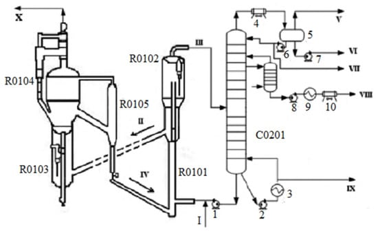
Figure 2.
General flow diagram of the catalytic cracking unit (R2R): R0101—riser, R0102—reactor-separator; R0103—stage one regenerator; R0104—stage two regenerator, R0105—section for blow off catalyst from smoke gases; C0201—distillation column; 1, 2, 3, 4, 5—pumps; 3, 9—coils; 4, 10—air cooling devices; 5—container; I—raw; II—coked catalyst; III—reaction product; IV—regenerated catalyst; V—gas; VI—acidic water; VII—petrol; VIII—light gas oil; IX—remainder of the above 343 C, X—flue gases.
The unit is designed to convert the residue of atmospheric distillation (AR, fuel oil), heavy gas oil, vacuum gas oil, heavy gas oil from (from coking unit), heavy raffinate (from plant for production of aromatics and heavy aromatic compounds) into more valuable products, such as liquefied petroleum gas, gasoline and light gas from catalytic cracking.
The catalytic cracking unit consists of two main parts: the reactor R0101, R0102 and the regenerator R0103, R0104 (Figure 2). The central part of the catalytic cracking unit is the R0101, R0102 reactor, which functions as follows: the raw material passes through the heater, mixes with the catalyst and enters a vertical pipe (riser) leading to the lower part of the large vessel (settling part of the reactor). The main task of the reactor is to separate hydrocarbons from the catalyst. This occurs in the settling zone of the reactor. The steam phase rises up and passes through the cyclones and is sent to the distillation column for further cleaning and processing. The solid phase (coked catalyst) due to the difference in the static pressure of the catalyst in the reactor and the regenerator flows by gravity along an inclined transport line to the regenerator R0103. Some of the hydrocarbons that are converted to coke during cracking are deposited on the catalyst. When the surface of the catalyst is covered with deposits, the catalyst becomes inactive (spent). To remove these carbon deposits, the spent catalyst is fed to a regenerator, where it is mixed with hot air. As a result, coke is oxidized.
Catalytic cracking process is based on splitting high molecular hydrocarbon compounds into smaller molecules together with redistribution of “carbon—carbon” bond of the hydrogen in the presence of microspherical zeolite containing a catalyst. Gas, gasoline, distillate fractions and coke on the surface of the catalyst are formed.
In order to improve the quality of raw materials for catalytic cracking, preliminary hydrotreating of raw materials has been introduced into the complex, which makes it possible to completely eliminate the influence of fluctuations in the quality of raw materials on the results of the cracking process and to stabilize the operation of the reactor-regenerator unit.
Raw material is injected into lower part of a riser where it is mixed with upstream hot catalyst. At the top of the riser, the mixture passes through a separator where hydrocarbon vapors are separated from the catalyst. Cracked products are sent to a fractionation column where reaction products are separated (Figure 3).
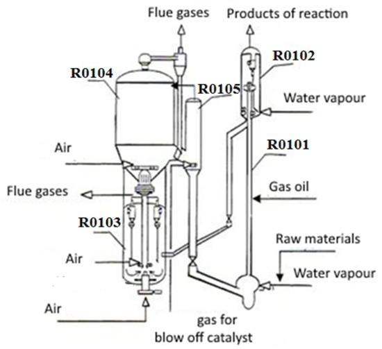
Figure 3.
Scheme of reactor block of a Fluid Catalytic Cracking (FCC) R-2-R unit: R0101—riser; R0102—reactor—separator; R0103—stage one regenerator; R0104—stage two regenerator; R0105—section for blow off catalyst from smoke gases.
Hence, regeneration proceeds in two stages and it is a distinctive feature of R2R process. Within stage one regenerator that operates at temperature not exceeding 730 C, partially burns of carbon (about 50–80% ) the rest of coke burns within the second regenerator. Combustion air is supplied by a blower through the manifold system.
There are nozzles above the zone for feeding raw materials. These nozzles are designed to feed heavy gas oil for catalytic cracking that is intended to supply a circulating hydrocarbon stream from the main fractionation column. Heavy gasoil of catalytic cracking is received to increase conversion of residue and control coke load to the regenerator. Reaction products are separated into target fractions within the primary rectification column. The main target product, catalytic cracking gasoline, passes stabilization unit and enters selective hydrogenation unit of catalytic cracking naphtha.
Distinctive features of reactor—regenerative block is the availability of two regenerators that have separate air supply and flue gas removal. The first regenerator (along the catalyst) is designed to burn 50–80% of coke at temperatures of 680–700 C without CO afterburning or its partial afterburning. At the same time, coke protective shell protects the catalyst from thermocouple deactivation. The second regenerator has temperatures up to 800 C, excess air and minor amount of water vapor that eliminate thermocouple deactivation. It is designed to burn the rest of the coke. The second regenerator is equipped with an external cyclone and a desorber (zone of catalyst for blowing off flue gases). High temperature within the mixing unit (it may be 40–100 C higher than one within the reactor) ensures fast and almost complete evaporation of raw material, reduces coke formation.
Another distinctive feature of R2R process is that there is supply of chilled circulating gas oil (fr. 360–420 C) to the riser above the feed point. It allows to control temperature within the riser regardless of temperature within the mixing unit. Temperature within the reactor is about 510 C, contact time is about 1 s. For R2R process reactor, an original device is used (distribution head), a Laval’s nozzle or Venturi pipe. These operate at speeds close to sonic ones, shock (acoustic) wave occurs that disperses raw material into drops that are comparable or smaller than particles of the catalyst (40–80 microns). Hence it results in instant heat transfer and evaporation, and together with recirculation of cold gas oil, it reduces gas and coke formation and allows deeper cracking. Rise (lift reactor) is used in the process that ends with a device for rapid separation of vapor from the catalyst. Blowing off regenerated catalyst reduces the content of inert gases content within the dry gas by 50%.
Installation blocks and aggregates are interconnected, and changes in the operating parameters of one of them lead to changes in the parameters of the other, which affect the processes.
To optimize and control catalytic cracking in a rational mode, with the purpose of its intensification, it is necessary to have structured (linked) mathematical models, developed on the basis of a system approach. They should take into account the influence of technological parameters on each unit, intermediate and final products and the operation of the whole setup.
3. Results and Discussion
3.1. Development of a Method for Conducting Expert Procedures within Fuzzy Environment
After analyzing current problems in mathematical modeling for technological objects of oil refining, main characteristics and issues on increasing efficiency of their functioning according to economic and environmental criteria as well as issues on decision making (DM) for selecting optimal operating modes of objects of the complex were considered. Results of a study on various approaches for construction of models of technological objects for oil refining and optimization of their operation proved that application of traditional modeling methods and decision making under industrial conditions is often ineffective due to the lack, unavailability of reliable information on parameters of objects.
Under these conditions, the promising means of obtaining and processing initial fuzzy information (knowledge, human experience) are expert assessment methods and theory of fuzzy sets that aim at efficient modeling and selection of optimal modes for technological objects [14,15]. We have analyzed various types of models of main units within reactor block of catalytic cracking unit at Atyrau Oil Refinery. Let us consider the main results of organization and conduct of expert assessments in order to collect necessary information for development of mathematical models of technological objects of oil refining. Let us use parts of reactor block of catalytic cracking unit. The primary goal of organizing and conducting an expert assessment was to find out and select the most significant input, operating, and output parameters of an object with consideration of their degree of importance (weights). A fragment of assessment results is ranked in Table 1.

Table 1.
List of input and operating parameters of reactor block within catalytic cracking unit as well as results of expert assessment.
According to results of the survey, experts have ranked the selected parameters in numerical form. They mainly used only a few numbers from the interval of 1 to 4 for evaluation of results.
Thus, according to results of expert evaluation and research, it was revealed that main input/operational parameters that significantly affect catalytic cracking process include the following: volume and speed of loading of raw materials, temperature at input/output of R0102, R0103, R0104 reactors-regenerators, pressure within such reactors, temperature, hydrogen and feed ratio and properties of raw materials.
Due to complexity of technological processes and oil refining facilities, shortage or lack of industrial measuring and control devices, presence of human operator in the control process, information collected about their functioning is considered to be fuzzy. Under such conditions, it is necessary to conduct expert procedure within fuzzy environment to assess fuzzy parameters [16]. Development of procedures for data assessment and selection of decisions in the presence of fuzzy factors is based on the use of expert opinions and theory of fuzzy sets.
Results of work of any CES may generally be estimated via vectors of criteria of two types: volumes of produced products (oil products in our case) and quality indicators of target products. Volumes of products are defined by different indicators: general, sent, normative net product, etc. In our case the volume of target product-catalysate is measured in m/hour within the interval of [64 ÷ 80]. Some problems occur while assessing quality of target product. Quality assessment of catalysate by one number is very difficult or is impossible. In the problem below, quality of catalyst is defined by the following indicators:
- -
- octane number of a catalysate (according to motor method is not less than 86, i.e., fuzzy
- -
- fractional composition of catalysate –10% and 50% refine, and respectively at approximately 70 and 115 C,
- -
- pressure of saturated steam—no more than mm of mercury,
- -
- resin content in 100 mL. of gasoline—no more than mg.
As we can see quality indicators of target products are assessed via fuzzy criteria or restrictions such as “not less than”, “about, approximately” or “no more than”. During decision making and management processes at production place, as a rule, we want that volume of target products to be more, and product quality to be better. These criteria are often controversial, i.e., after determination of Pareto set it is impossible to improve them at the same time. Thus while management of CES taking into account the situation at production place and production schedule it is necessary to find a compromise solution that satisfies requirements of PMD. Thus, we formalize the problem on selection and management for operational modes of CES for reforming block and set it in mathematical way as follows.
Let be normalized criterion that assesses output (volume) of target product of reforming block – catalysate. Let us assume that the membership functions of accessory for each fuzzy restriction are built and they describe quality indicators of catalysate. A number of priorities for restrictions or vector of scales showing mutual importance of these restrictions are known.
In the conditions of multicriteriality and illegibility, the formalized problem can be set in the form of uncertain/fuzzy mathematical programming (FMP):
or
The optimal solution for this problem is the vector regime, entrance parameters = (, , …, ), which provide extreme values of criteriaI at compliance with imposed restrictions that consider and satisfy preferences of PMD.
Criterion , and restrictions depend on vector of entrance, regime parameters : —volume of raw materials; —temperature and pressure in reactors of reforming R-4, R-4a; —rate of volume flow for raw materials; —relation of hydrogen/hydrocarbon. These dependences are defined on the basis of mathematical models of reforming process that are developed taking into account shortage and illegibility of initial information. Let us consider the suggested system approach on development of models and modeling CES where we take the reforming block of catalytic reforming unit in the Atyrau Oil Refinery as an example.
3.2. Model Building of Main Parts of Reactor Block of Fluid Catalytic Cracking Unit
When building models of chemical and technological systems, which is a complex of interconnected aggregates of various types (technological installations) with different initial information, it is necessary to use combined information. Based on the research results, we develop a mathematical description and models of aggregates.
We specify and implement above mentioned theoretical results of the research based on development of mathematical models of main technological units of the reactor block of FCCU within Atyrau Oil Refinery. We study the main parameters of this block and their influence on technological process. Hence, they further serve as a basis for mathematical models and package of models for technological units of reactor block of fluid catalytic cracking unit (FCCU) [17].
As a result of processing experimental statistical and expert data as well as applying idea/method on sequential inclusion of regressors based on algorithms of fuzzy model (FM) [18] and logical model (LM) of synthesis of mathematical models within fuzzy environment, the following system of equations of multiple, qualitative regression and conditional inference (they are models of reactor) [19] were calculated in the form of (3, 4):
where:
- —volume of catalyst (target product) from output of reactor,
- —quality indicators of catalysate octane number —not less than 91 according to motor method),
- —raw materials, hydrogenate from discharge of hydrotreating unit, m/hour,
- —volumetric flow rate within reactors, hour,
- —temperature within reactors, C,
- —pressure within reactors, kg/cm,
- —/raw materials ratio, nm.
Hence, models that describe production volumes from output of reactor block are built according to experimental and statistical methods in the form of multiple regression models. Models that describe qualitative indicators of products are built on the basis of fuzzy information received from expert in the form of fuzzy multiple regression equations [20]. Coefficients of models (Equations (3) and (4)) were determined with well-known parametric identification methods based on the least squares method (Regress and MatLab software [21]). Results of parametric identification of models that determine volumes of catalysis from output of the reactor are given in the form of (Equations (5) and (6)):
The mathematical models describing dependence of quality indicators of catalysate on mode parameters () are identified in the following form (for —octane number of catalysate):
Simulations of reactor operation modes were performed using the developed models in order to optimize the process. To compare the obtained simulation results with results generated by other models and evaluate the adequacy of the developed models with real experimental and production data of the reactor under study, the following table is constructed (Table 2).
Table 2.
Comparison of simulation results using well-known deterministic models, based on expert information and experimental production data of the reactor of the Atyrau Oil Refinery’s catalytic cracking unit.
As can be seen from the data shown in Table 2, as a result of modeling the developed models with fuzzy information based on expert evaluation, better and more adequate results were obtained with real production data. The proposed models can be used to optimize the process of operating modes of the catalytic cracking unit reactor with a relative deviation of less than 1%.
In addition, the developed models, which take into account additional fuzzy information in the form of knowledge, experience and intuition of experts, enable determination of some important product quality indicators. These include composition of sulfur, acids and alkalis in the product, the octane numer of the product, fractional composition of catalysis, for whom deterministic models have not been defined.
In the course of research the developed model was used for calculations to study the effect of temperature of catalyst after regeneration on input and composition of cracking products. Results of research are shown in Figure 4.
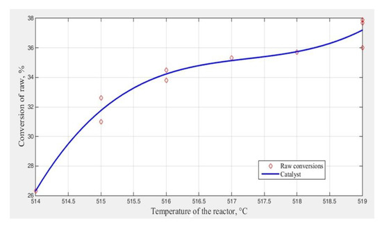
Figure 4.
Dependence of conversion of raw materials on temperature of catalyst.
According to the dependence shown (Figure 4), the increase of temperature (from 500 to 520 C) of catalyst after regeneration results in increase of process temperature. Linguistic model was built that describes the effect of temperature of cracking reactor on catalyst’s output and stability. Its designation is to determine optimal temperature of cracking process on the basis of logical rule of conditional conclusion and base of knowledge.
To determine the optimum temperature of the catalytic cracking process, based on the proposed method of developing models of technological complexes based on various types of information, linguistic models are constructed that determine the influence of the cracking reactor temperature on the output of the catalyst and the stability of the catalyst. These models describe linguistic connection and presented it in the following form:
- “If is low, is below the average, is lower than the average,
- if is average, is average, is normal,
- if is high, is above the average, is higher than the norm”.
where: —is temperature of reactor, —output of catalysate from the reactor, —stability of catalysate.
To build a membership function, i.e., fuzzification of fuzzy parameters , and , results of expert evaluation are applied:
- —reactor’s temperature is low,
- —reactor’s temperature is average,
- —reactor’s temperature is high,
- —discharge of catalysate is low,
- —discharge of catalysate is average,
- —discharge of catalysate is higher than the average,
- —stability of catalysate is lower than normal,
- —stability of catalysate is normal,
- —stability of catalysate is higher than normal.
Based on rules of logical conclusion and linguistic dependence stated above according to the method, the following linguistic models were obtained which describe temperature influence () and pressure () of reactor on discharge of catalysate () from reactors and stability of catalyst ( ).
Fuzzy reflection may be presented in the form of knowledge base or linguistic model as follows:
where: NB—negative big, NS—negative small, N—normal, PS—positive small, PB—positive big;
—input and output linguistic variables that describe temperature of reactor, output of catalysate and stability of catalysate;
are fuzzy sets that describe input and output parameters.
Using the membership functions of the MATLAB Fuzzy Logic Toolbox package [22], we set the membership function for terms of selected linguistic changes, using the experience of experts. The general view of the gbellmf membership function in the membership function Editor window is shown in Figure 5.
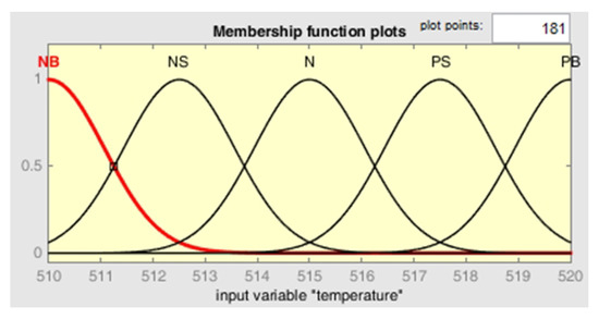
Figure 5.
Membership function for the temperature within reactor.
The fuzzy output system rule editor is designed for setting and editing individual fuzzy output system rules in a graphical mode. A fragment of the rule base for reactor temperature is shown in Figure 6.

Figure 6.
Fuzzy knowledge base for input and output parameters.
For the reactor temperature, the surface of the fuzzy output is obtained, the dependence of the output variable on the input one (Figure 7).

Figure 7.
The surface of fuzzy inference.
The results show the effectiveness of the proposed method for solving the problem of controlling the modes of operation of chemical and technological systems in a fuzzy environment, since the results of known methods and production-experimental data for all indicators show acceptable result. When solving a fuzzy control problem, fuzzy constraints are fully fulfilled: the membership functions are equal to 1, and the degrees of fuzzy constraints are improved. Optimal modes are provided at a temperature of 51 C in reactors.
4. Conclusions
The paper proposes a method for developing models of chemical and technological systems (CTS) using the example of catalytic cracking installation in conditions of scarcity and fuzziness of initial information, based on the use of methods of system theory, expert evaluation methods and fuzzy set theory. The main points of implementation of the proposed method are described. On the basis of the proposed methodology, fuzzy models can be developed that have the structure of fuzzy multiple regression equations with fuzzy coefficients, and linguistic models based on the application of logical rules for conditional inference.
Novelty of results is that tasks involving selection of optimum operating modes for the object are set and solved in uncertain environment without their preliminary transformation to determined equivalent problems. In turn it allows to describe industrial situations under uncertain environment in a more accurate way and obtain effective solutions for problems related to management of operating modes of the object. The proposed approach was implemented to develop a mathematical model to solve the problem of choosing the optimal operating mode of the catalytic cracking reactor for chemical and technological systems for the production of high-octane gasoline in a fuzzy environment.
Author Contributions
B.O.: Studied a set of mathematical models for system modeling of technological units of the catalytic cracking unit, developed a method for conducting expert procedures in a fuzzy environment. D.K.: Conducted expert procedures in a fuzzy environment and implemented software in MatLab. R.W. conducted data analysis, consulted the analyzed issue in terms of engineering and process, prepared the manuscript in terms of graphics and editing, also did final proofreading. J.K. consulted the analyzed issue in terms of engineering and process. All authors have read and agreed to the published version of the manuscript.
Funding
This research received no external funding.
Conflicts of Interest
The authors declare no conflict of interest.
Abbreviations
The following abbreviations are used in this manuscript:
| CTS | Chemical-technological system |
| DM | Decision making |
| FCC | Fluid catalytic cracking |
| FCCU | Fluid catalytic cracking unit |
| FM | Fuzzy model |
| FST | Fuzzy set theory |
| LM | Logical model |
| PMD | Person making decisions |
| R2R | Vacuum, two-stage regeneration system |
References
- Nazarova, G.R.; Burumbaeva, G.J.; Seytenova, G.J. The testing of a kinetic model of FCCU in the “C-200” section of the KT-1/1 installation of oil refining plants in Kazakhstan—Chemistry and chemical technology in the XXI century. In Proceedings of the XVII International Scientific and Practical Conference 2016, Tomsk, Russia, 17–20 May 2016; pp. 513–515. [Google Scholar]
- Orazbayev, B.B.; Ospanov, Y.A.; Orazbayeva, K.N.; Makhatova, V.E.; Urazgaliyeva, M.K.; Shagayeva, A.B. Development of mathematical models of R-1 reactor hydrotreatment unit using available information of various types. J. Phys. Conf. Ser. 2019, 1399, 044024. [Google Scholar] [CrossRef]
- Pashayeva, B. Mathematical Model of the Fluid Catalytic Cracking for Work in Testing Control Systems for the Cracking Plant; PCI: Baku, Azerbaijan, 2010; pp. 328–331. [Google Scholar]
- Mircea, C.; Agachi, S.; Marimoiu, V. Simulation and model predictive control of a UOP fluid catalytic cracking. Chem. Eng. Process. 2003, 42, 42–67. [Google Scholar] [CrossRef]
- Yidi, B.S. TAI, Research Project. In Lignin Fast Pyrolysis: Towards Enhanced Product Selectivities by Varying Particle Sizes of H-ZSM5 Zeolites; Swiss Federal Institute of Technology Zurich (ETH Zurich): Zurich, Switzerland, 2016; p. 72. [Google Scholar]
- Osman, A.I. Catalytic hydrogen production from methane partial oxidation: Mechanism and kinetic study. Chem. Eng. Technol. 2020, 43, 641–648. [Google Scholar] [CrossRef]
- Harinath, E.; Biegler, L.T.; Dumont, G.A. Predictive optimal control for thermo-mechanical pulping processes with multi-stage low consistency refining. J. Process. Control 2013, 47, 1001–1015. [Google Scholar] [CrossRef]
- Pavlov, S.Y.; Kulov, N.N.; Kerimov, R.M. Improvement of chemical engineering processes using systems analysis. Theor. Found. Chem. Eng. 2016, 53, 117–126. [Google Scholar] [CrossRef]
- Dzhambekov, A.M.; Sherbatov, I.A. Control of catalytic reforming process based expert information. Syst. Method Technol. 2014, 4, 103–111. [Google Scholar]
- Orazbayev, B.B.; Ospanov, E.A.; Orazbayeva, K.N.; Kurmangazieva, L.T. A hybrid method for the development of mathematical models of a chemical engineering system in ambiguous conditions. Math. Models Comput. Simul. 2018, 10, 748–758. [Google Scholar] [CrossRef]
- Kim, S.W.; Yeo, C.E.; Lee, D.Y. Effect of fines content on fluidity of FCC catalysts for stable operation of fluid catalytic cracking unit. Energies 2019, 12, 293. [Google Scholar] [CrossRef]
- Technological Regulations for the Catalytic Reforming Installation LG-35-11/300-95; 130c; Atyrau Oil Refinery: Atyrau, Kazakhstan, 2002.
- Roudneshin, M.; Azadeh, A. A novel multi-objective fuzzy model for optimization of oil sludge management by considering health, safety andeEnvironment (HSE) and resiliency indicators in a gas refinery. J. Clean. Prod. 2019, 206, 559–571. [Google Scholar] [CrossRef]
- Nourian, R.; Meysam Mousavi, S.; Raissi, S. A fuzzy expert system for mitigation of risks and effective control of gas pressure reduction stations with a real application. J. Loss. Prevent. Proc. 2019, 59, 77–90. [Google Scholar] [CrossRef]
- Ying, H. Fuzzy Control and Modeling: Analytical Foundations and Applications; Wiley-IEEE Press: Hoboken, NJ, USA, 2000. [Google Scholar]
- Mehran, K. Fuzzy Modeling for Process Control; School of Electrical, Electronic and Computer Engineering: Wuhan, China, 21 January 2008; p. 21. [Google Scholar]
- Zhu, B. A novel multiscale ensemble carbon price prediction model integrating empirical mode decomposition, genetic algorithm and artificial neural network. Energies 2012, 5, 355–370. [Google Scholar] [CrossRef]
- Shumsky, V.M.; Zyryanova, L.A. Engineering Tasks in Oil Refining and Petrochemistry; MPC Publ.: Moscow, Russia, 2014; p. 475. [Google Scholar]
- Tchoketch Kebir, G.F.; Larbes, C.; Ilinca, A.; Obeidi, T.; Tchoketch Kebir, S. Study of the intelligent behavior of a maximum photovoltaic energy tracking fuzzy controller. Energies 2018, 11, 3263. [Google Scholar] [CrossRef]
- Leanenkov, A.V. Fuzzy Modeling in Matlab and FuzzyTech; BHV: Sankt Petersburg, Russia, 2005; pp. 725–727. [Google Scholar]
- Shtovba, S.D. Design of Fuzzy Systems by Means of Matlab; MathWorks: Moscow, Russia, 2007. [Google Scholar]
- Fuzzy Logic Toolbox. Available online: http://www.matlab.ru (accessed on 1 September 2020).
© 2020 by the authors. Licensee MDPI, Basel, Switzerland. This article is an open access article distributed under the terms and conditions of the Creative Commons Attribution (CC BY) license (http://creativecommons.org/licenses/by/4.0/).