Article

An Improvement of Output Power in Doubly Salient Permanent Magnet Generator Using Pole Configuration Adjustment

by
Warat Sriwannarat
1,
Pattasad Seangwong
2,
Vannakone Lounthavong
2,
Sirote Khunkitti
3,
Apirat Siritaratiwat
2 and
Pirat Khunkitti
2,*
1
Department of Electrical and Computer Engineering, Kasetsart University Chalermphakiet, Sakon Nakhon 47000, Thailand
2
Department of Electrical Engineering, Faculty of Engineering, Khon Kaen University, Khon Kaen 40002, Thailand
3
Department of Electrical Engineering, Faculty of Engineering, Chiang Mai University, Chiang Mai 50200, Thailand
*
Author to whom correspondence should be addressed.
Energies 2020, 13(17), 4588; https://doi.org/10.3390/en13174588
Submission received: 15 June 2020 / Revised: 27 August 2020 / Accepted: 31 August 2020 / Published: 3 September 2020
(This article belongs to the Section F: Electrical Engineering)

Abstract

:
The doubly salient permanent magnet (DSPM) machines are very attractive for low-speed power generation. In this work, we propose a design technique to improve the output power of the DSPM generator by an adjustment of pole configuration. The number of stator and rotor poles, split ratio, as well as the stator pole arc of the generator, were proposedly adjusted and optimized. The output characteristics of the generator including the magnetic flux linkage, electromotive force, harmonic, cogging torque, electromagnetic torque, output voltage and output power were analyzed through finite element analysis. The symmetrical magnetic field distribution of all generators was firstly verified. Then, the results indicated that this particular generator was optimized at 18 stator poles and 12 rotor poles, while the split ratio and the stator pole arc should be set as 0.78 and 6.15 degrees, respectively. The proposed optimal generator could provide a significant improvement in the output voltage and the output power compared to the conventional structure. The output power of 1.28 kW can be reached by the optimal structure, which was two times higher than that of the conventional structure. The physical explanation regarding to the structural modification was also given. The proposed design technique can be applied for improving the output power of the DSPM machines.

Graphical Abstract

1. Introduction

Permanent magnet (PM) machines have received considerable research attraction over the past decades mainly due to their outstanding features, such as high torque density, high power density, high reliability, robust structure and low thermal impact [1,2]. There are two main categories of the PM machines which are the stator PM machines, in which the PMs are installed at the stator, and the rotor PM machines, in which the PMs are embedded at the rotor [3]. The stator PM machines have been extensively researched in several publications because they have many merits over the rotor PM machines, especially their significantly lower rotor weight and inertia [4,5,6]. Several studies have attempted to improve the performance of stator PM machines by using various techniques. The main proposed structures are the flux-reversal PM machines [3,7], the switched-flux PM machines [8,9] and the doubly salient permanent magnet (DSPM) machines [10,11]. In particular, the DSPM machines, in which all PMs are located at the stator slot opening, incorporate remarkable qualifications over the other machine types, such as simple configuration, high efficiency, high power density, good mechanical integrity and robustness [12,13,14]. These machines also indicate high cost efficiency, since they require less magnet volume compared with the conventional PM synchronous machines. Many studies have claimed that the DSPM machines are appropriate for low-speed power generation, which is well known as a doubly salient permanent magnet generator (DSPMG) [5,15,16]. Several outstanding properties of the DSPMG were reported afterward [5,16,17].
However, the DSPMG still suffers from the non-sinusoidal back electromotive force (EMF), high cogging torque and torque ripple [18]. Therefore, many techniques were proposed to improve the electrical performance of the DSPMG, such as designing stator teeth and rotor pole arcs, dual rotor structure and optimizing phase number [3,17,19]. Several optimization approaches have been performed in the analytical calculations of machine design, such as 2-D or 3-D finite element simulations, control-related design, system-level optimization, Fourier analysis and magnetic equivalent circuit method [20,21,22,23]. In particular, the number of stator and rotor poles were widely known as a crucial factor influencing the performance of DSPMG, as can be seen in many examples in the literature [24,25]. Recently, we proposed the stator modification technique applied to the three-phase DSPMG having 12/8 (stator/rotor poles) structure [26]. It was found that this technique could improve the performance of the DSPMG. Nevertheless, we noticed that the performance of this generator can be increasingly improved.
Therefore, the aim of this paper is to propose a novel design technique to improve the performance of the DSPMG. The pole configuration of the DSPMG was designed by optimizing the number of stator and rotor poles, split ratio and stator pole arc. The output characteristics of the DSPMG including the magnetic field distribution, magnetic flux linkage, EMF, harmonic, cogging torque, electromagnetic torque, output voltage and output power were demonstrated. The finite element method was performed in the simulations.

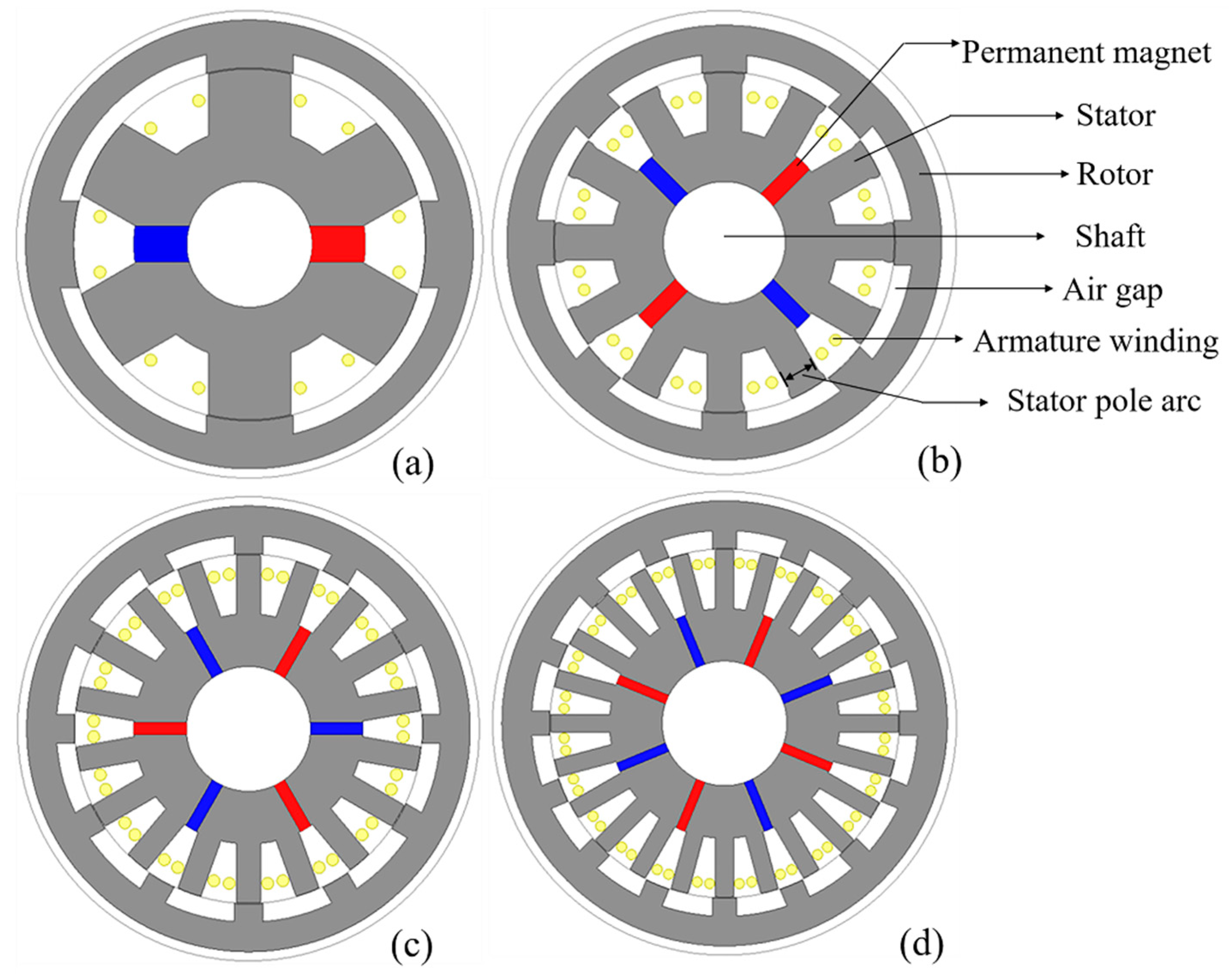
2. Structural Topology and Key Design Parameters

The conventional structure of the DSPMG focused in this work has been developed in our previous publication, as shown in Figure 1b [26]. This structure includes 12 stator poles and 8 rotor poles, written as 12/8 (stator/rotor) poles. In this work, we proposedly designed new machine structures by varying the number of stator and rotor poles, split ratio as well as optimizing the stator pole arc in order to improve the electrical performance of the DSPMG. A combination of stator and rotor poles was set based on the basic principle of the DSPM machines in which the number of stator pole should be above the number of rotor poles. The appropriate combination of stator and rotor pole number can be set from a basic operation of DSPM machines [27]. The number of stator pole, Ns, is initialized as Ns = 2mk where m is the number of generator phase and k is a positive integer. Then, the number of rotor pole, Nr, is given as Nr = Ns ± 2k. However, our analysis found that the relationship of rotor pole indicates the acceptable output for the DSPMG only by the relation Nr = Ns−2k at k = 1 to 4; other values of k yield significantly worse machine performance.
Figure 1a–d shows the proposed DSPMG structures with 6/4, 18/12 and 24/16 poles where the 12/8 poles structure is considered as a conventional structure. Since the suitable configuration of the conventional 12/8 poles structure was already made in the previous publication [26], there will be no further modification of this structure. The stator and rotor poles of all structures were a salient pole. The Nd–Fe–B permanent magnet was used to supply a magnetic field excitation, and all magnets were inserted at the stator yoke. Since the permanent magnets and armature windings are assembled at the stator, the rotor of this particular DSPMG structure could be a very low weight. The winding coils were inserted at the stator slot opening. The structural parameters of all DSPMG structures are illustrated in Table 1.
The goal to improve the performance of DSPMG in this work was to enhance the output power of the generator by adjusting the number of stator and rotor poles, split ratio, and stator pole arc. The number of stator and rotor poles normally indicates a strong influence on the magnetic field circulating behavior; meanwhile, the split ratio is generally known as the major parameter related to the performance of DSPMG. Additionally, the stator pole arc is directly related to the shape of magnetic field path as well as a stator slot opening area for installing the winding coil. Accordingly, those factors could play a crucial role in the performance of the generator. The number of stator and rotor poles was firstly adjusted as 6/4, 18/12 and 24/16 poles, then the split ratio and the stator pole arc of those structures were adjusted afterward. While adjusting the number of stator and rotor poles, the configuration of stator teeth was designed with maintaining the equality of stator teeth area and stator slot opening. The rotor configuration was then designed based on maintaining the suitable ratio between rotor and stator pole arc similarly to the conventional structure. Particularly, all structures were assumed to have the same total volume of permanent magnet. The rest of structural parameters were varied based on the linear order relation.

3. Results and Discussion

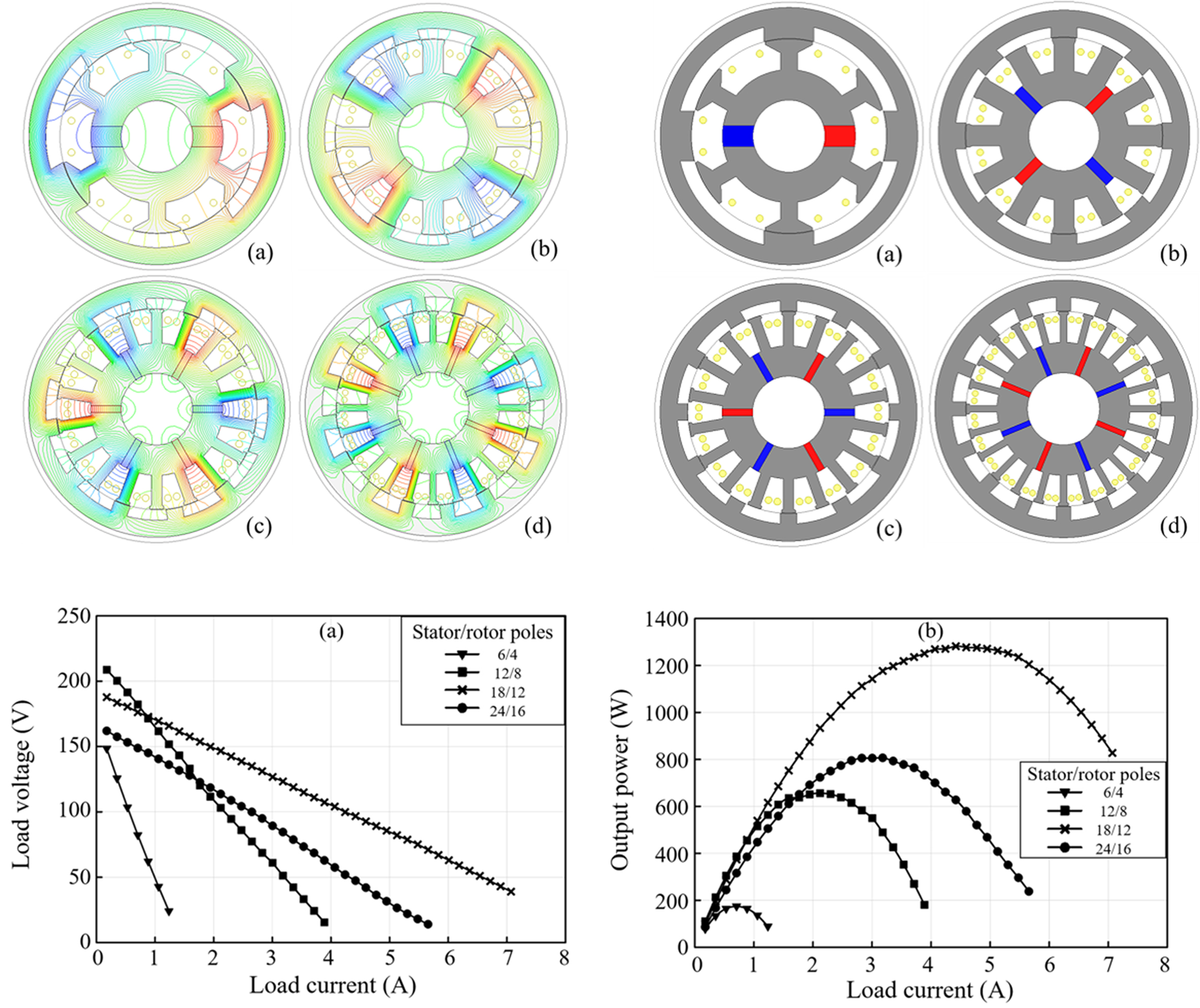
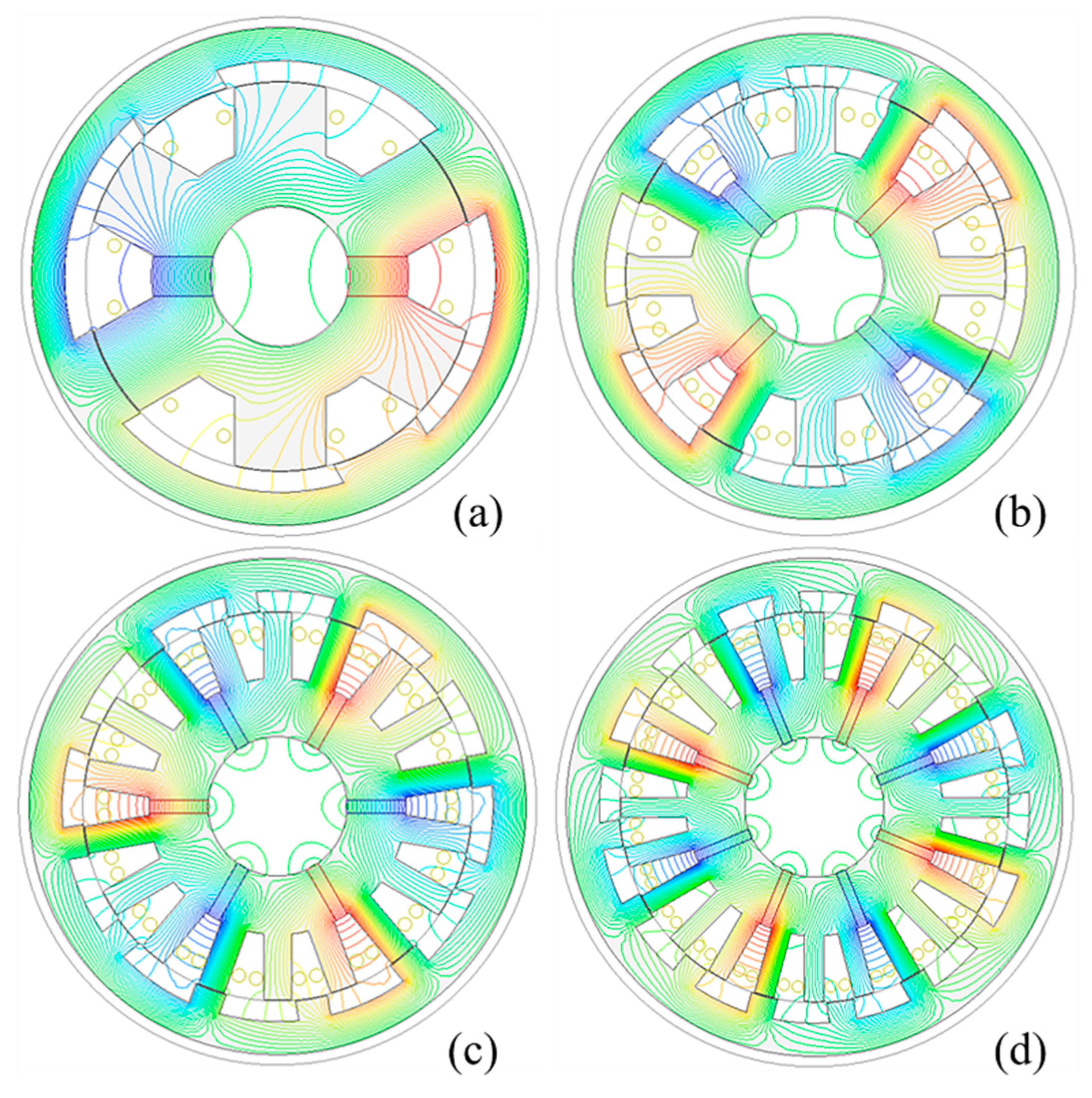
3.1. Number of Stator and Rotor Poles Influences on the Generator Outputs

In this section, the output characteristics of four generator structures, including the 6/4, 12/8, 18/12 and 24/16 poles structures were investigated. Since the number of stator poles was directly related to the stator opening slot area, the variation of the winding coil turn after adjusting the number of poles was taken into account. Table 2 demonstrates the winding turn per phase of each generator structure under the condition that the winding turn was limited by 90% of stator slot opening.

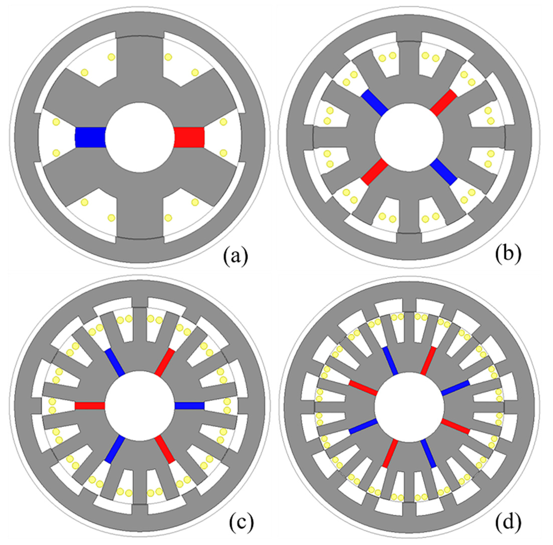
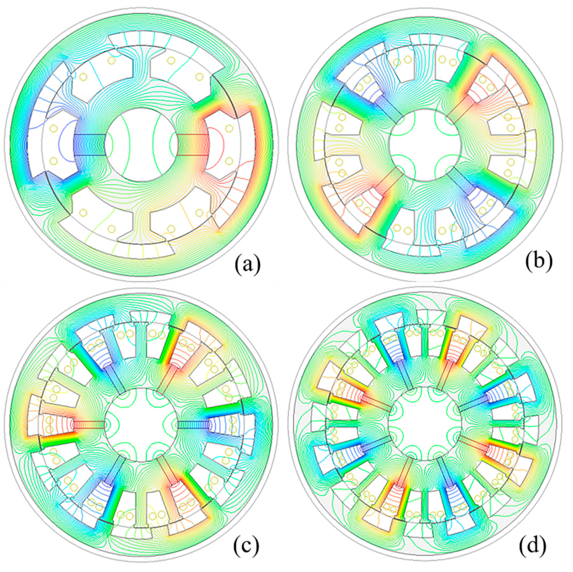
3.1.1. Magnetic Field Distribution Analysis

The magnetic field distribution in a no-load condition of the DSPMG with 6/4, 12/8, 18/12 and 24/16 stator/rotor poles are shown in Figure 2a–d, respectively. From the results, a symmetrical property of the magnetic field flowing through the generator structure was observed for all structures. The generators having a higher number of poles seem to indicate larger flux leakage due to their narrower teeth.

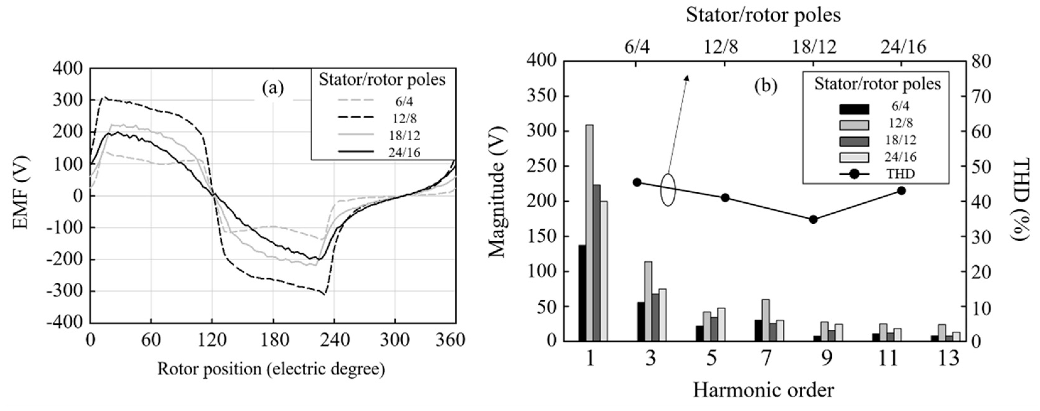
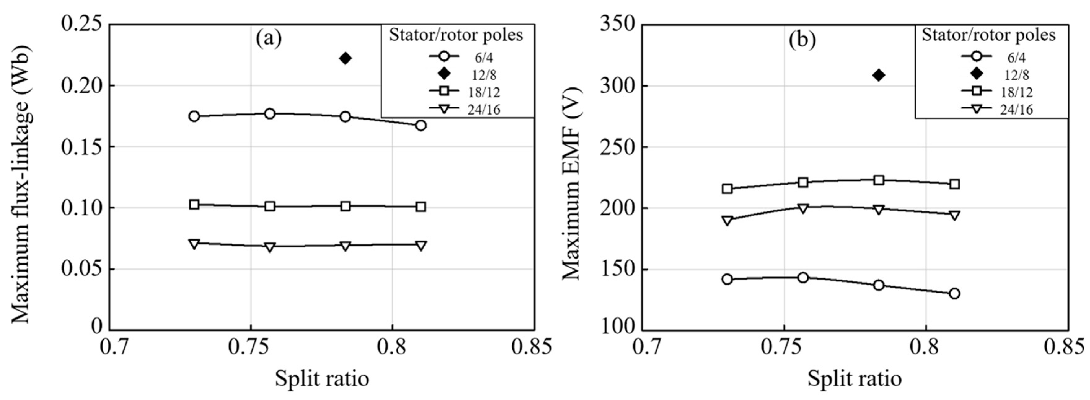
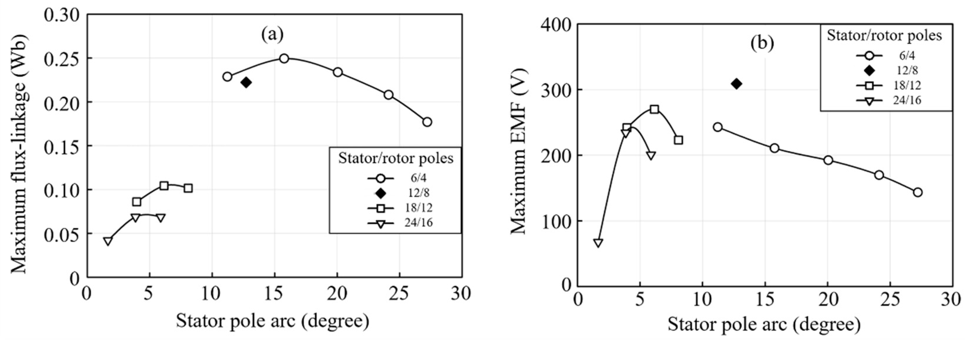
3.1.2. Phase PM Flux Linkage and EMF Analysis

Figure 3 illustrates the open circuit phase PM flux linkage waveforms of all proposed DSPMG structures. Due to the suitable configuration of magnetic flux path, the 12/8 poles structure demonstrates the highest flux linkage; followed by 6/4, 18/12 and 24/16 poles structure. The waveform of the 24/16 poles structure shows a greater symmetrical pattern than the others. The phase EMF waveforms produced by four proposed DSPMG structures are illustrated in Figure 4a, while the harmonic profiles of those structures are demonstrated in Figure 4b. The conventional 12/8 poles structure could produce the highest EMF magnitude; followed by 18/12, 24/16 and 6/4 poles structure. The harmonic profiles show that these machines could suffer from the harmonic distortion. Especially, the 18/12 poles structure indicated the smallest total harmonic distortion (THD), while the 6/4 poles structure demonstrated the worst harmonic distortion.

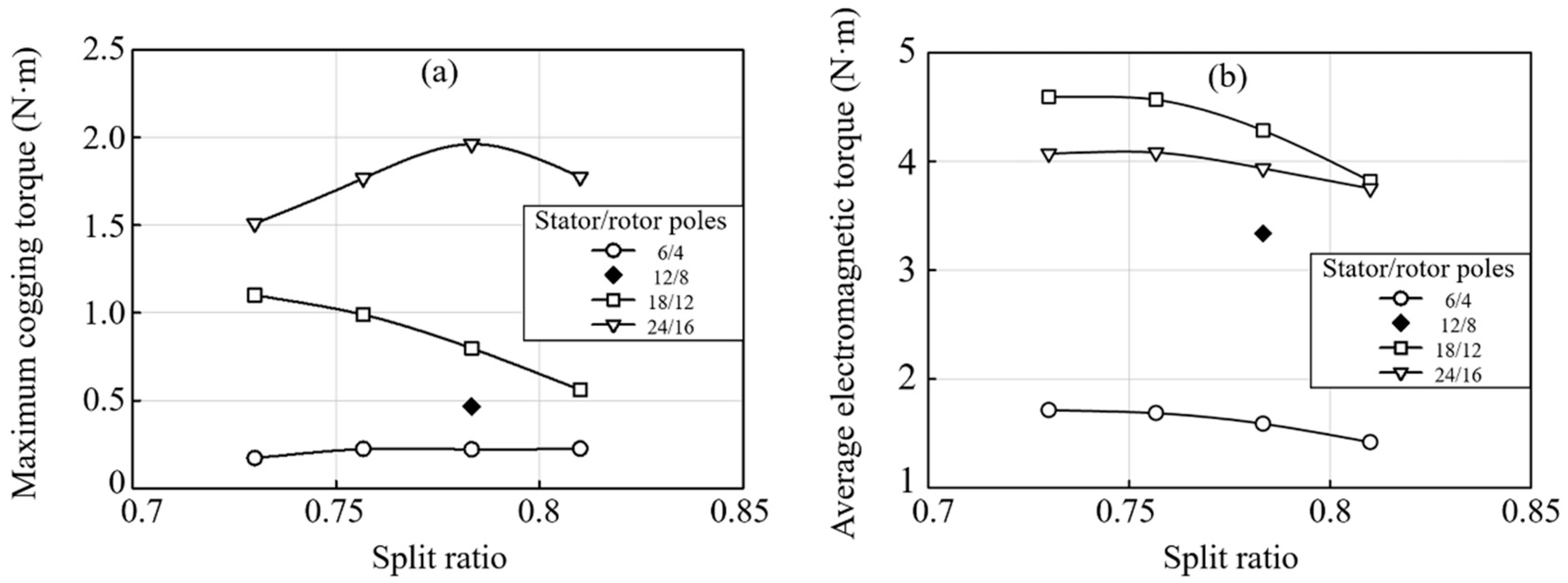
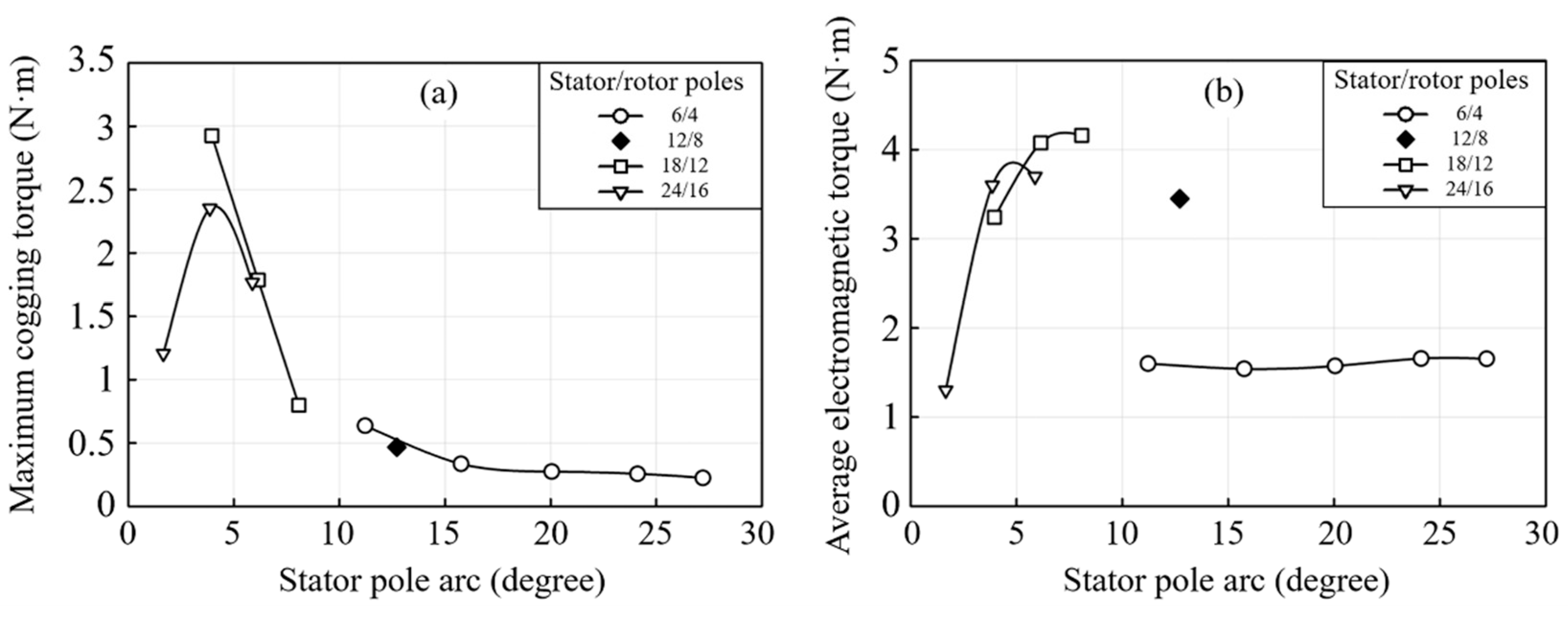
3.1.3. Analysis of Cogging Torque and Electromagnetic Torque

The cogging torque waveforms of all proposed structures are given in Figure 5a, showing that the 6/4 poles structure indicates the smallest cogging torque value; followed by 12/8, 18/12 and 24/16 poles structure. As expected, the 24/16 poles structure suffers from the highest cogging torque due to the highest number of permanent magnets attached inside the stator pole. Figure 5b demonstrates the on-load electromagnetic torque of all proposed structures calculated at the same copper loss of 82 watt. The generator with the 18/12 poles could produce the highest electromagnetic torque, followed by the 24/16, 12/8 and 6/4 poles structures, respectively. The torque waveform of the 6/4 and 12/8 poles structures contained lower ripple due to its smaller cogging torque.

3.2. Influences of Split Ratio on the Generator Outputs

The split ratio is widely known as an influential parameter strongly related to the performance of the DSPMG. It is defined as the ratio of the outer rotor radius and the outer stator radius; therefore, this parameter could significantly impact the magnetic field path of the machines. As mentioned in Table 1, the conventional value of split ratio for all structures was 0.78. In this sub-section, the split ratio influences on the generator performance was examined. The limitation of split ratio variation was the stator slot opening has to be sufficient to install the winding shown in Table 2, assuming that there was no modification on winding turn in this investigation. The step size of split ratio variation was determined by the winding diameter due to the practical reason for winding installation. The proposed DSPMG with the optimal value of split ratio is shown in Figure 6.

3.2.1. Magnetic Field Distribution Analysis

The magnetic field distribution at no-load condition of the proposed DSPMG models with the optimal split ratio is presented in Figure 7. The symmetrical distribution of the magnetic field was obviously found for all structures. When comparing the flux density at rotor yoke of the structures shown in Figure 7 with that of Figure 2, we found that optimizing the split ratio could cause the higher flux density at rotor yoke. Accordingly, this can improve the utilization of generator.

3.2.2. Magnetic Flux Linkage and EMF Analysis

The maximum value of magnetic flux linkage and EMF profiles of 6/4, 12/8, 18/12 and 24/16 poles structures at various split ratios are presented in Figure 8. The conventional structure shows the highest flux linkage and the EMF, since it was already optimized in the previous study. Additionally, it was found that the flux linkage and the EMF of the proposed structures could be enhanced after adjusting the split ratio, since this topology optimization can reduce the flux leakage occurring at the teeth. From the results, the optimal value of split ratio was selected by the criteria that the generator could produce the highest EMF, since the EMF is the major indicator strongly related to the power output of generator. Therefore, the optimal split ratio of the DSPMG having 6/4, 18/12 and 24/16 poles structures was 0.76, 0.78 and 0.76, respectively.

3.2.3. Analysis of Cogging Torque and Electromagnetic Torque

The maximum cogging torque and the average electromagnetic torque of the 6/4, 12/8, 18/12 and 24/16 poles structures at various split ratios are presented in Figure 9a,b, respectively. A variation of split ratio had a strong influence on the cogging torque of the 18/12 and 24/16 poles structures; meanwhile, the cogging torque profile of 6/4 poles structure was slightly changed with varying split ratio. In particular, the cogging torque of the structures that had an optimal split ratio was improved from the structures with conventional split ratio. In addition, the result of electromagnetic torque, calculated at the same copper loss of 82 watt, indicates that a change of split ratio could alter the magnitude of the torque. The structures having 18/12 and 24/16 poles could produce significantly higher torque than the conventional structure; meanwhile, the structure with 6/4 poles demonstrates the lowest torque magnitude. As expected, a trend of torque variation is similar to that of the EMF behavior, since it is proportional to each other. Therefore, the results of torque analysis could reasonably support the selected optimal split ratios.

3.3. Influences of Stator Pole Arc on the Generator Outputs

In this sub-section, the effects of stator pole arc variation on the generator output were examined. The stator pole arc of 6/4, 18/12 and 24/16 poles structures were decreasingly varied aiming to improve the electrical performance of the generator, while there was no modification of the conventional 12/8 poles structure due to its suitable pole arc. The optimal split ratios of 6/4, 18/12 and 24/16 poles structures were fixed to be 0.76, 0.78 and 0.76, respectively. When reducing the stator pole arc, a trapezoid outer stator tip was designed for providing an efficient magnetic flux path as well as reducing the flux-leakage. The step size for reducing the stator pole arc was determined by the arc angle in which one column of a winding coil could be further installed on each side of stator pole.
Figure 10a–d indicates the 6/4, 12/8, 18/12 and 24/16 poles DSPMG with an optimal pole arc value: the detail of this optimal value will be clarified in the Discussion. Once the stator pole arc was reduced, an area for installing an armature winding at the stator slot opening practically became larger. A relationship between the number of installed winding turns and the stator pole arc of each DSPMG structure is shown in Table 3. Then, the magnetic field distribution, magnetic flux linkage, EMF, harmonic, cogging torque, output voltage and output power of DSPMG at various stator pole arcs were analyzed.

3.3.1. Magnetic Field Distribution Analysis

The magnetic field distribution at a no-load condition of the proposed DSPMG models with optimal stator arc is presented in Figure 11. The symmetrical distribution of the magnetic field was obviously found for all structures. When comparing the flux density at rotor yoke of the structures shown in Figure 11 with that of Figure 8, it was found that the magnetic flux leakage of the structures with narrower stator pole arc were higher than the structures with conventional pole arc due to the narrower stator teeth. The flux leakage obviously appeared at the stator(rotor) slot opening and the shaft, especially in 18/12 and 24/16 poles structures.

3.3.2. Magnetic Flux Linkage and EMF Analysis

The maximum value of magnetic flux linkage and EMF profiles of 6/4, 12/8, 18/12 and 24/16 poles structures at various stator pole arcs were presented in Figure 12. The results indicated that both magnetic flux linkage and EMF were strongly impacted by a variation of stator pole arc. When reducing the stator pole arc, it was found that the magnetic flux linkage and EMF were increased until the maximum value, and then rapidly reduced at narrower stator pole arcs. The magnitude of the EMF generated by the conventional structure was still higher than all proposed structures.
The theoretical discussion regarding a change of magnetic flux linkage and EMF with varying stator pole arc is given as follows: an increase of stator pole arc normally results in the narrower stator teeth which are used as the magnetic flux path. Although the additional winding coils can be installed at narrower pole arc to raise up the EMF magnitude, the too narrow magnetic flux path could increasingly cause magnetic flux leakage within the generator structure as well as reduce the structural robustness. This accordingly yields a reduction in the magnetic flux linkage and EMF scale. From the results, it was found that the optimal stator pole arc of proposed 6/4, 18/12 and 24/16 poles structures were determined as 11.21, 6.15 and 3.86 degrees, respectively. The structures having an optimal stator pole arc could generate the maximum EMF of 243, 270 and 234 V, respectively.

3.3.3. Analysis of Cogging Torque and Electromagnetic Torque

The maximum cogging torque and average electromagnetic torque of the 6/4, 12/8, 18/12 and 24/16 poles structures at various stator pole arcs are presented in Figure 13a,b, respectively. The generator containing a higher number of permanent magnets increasingly suffers from the higher torque at the starting condition. A variation of stator pole arc demonstrates a strong influence on the cogging torque only for the 18/12 and 24/16 poles structure; meanwhile, the cogging torque profile of the 6/4 structure was slightly varied with varying stator pole arc. Although the cogging torque of the structures with optimal stator pole arc became slightly higher than the conventional pole arc, the EMF of those structures were significantly improved. In addition, the result of electromagnetic torque demonstrates that the average torque becomes smaller at narrower stator pole arcs. This was because the additional winding turns were installed at narrower stator arcs, leading to the lower required stator slot current densities applied to the generator during torque calculation. At the optimal stator arc value, the structures having the 18/12 poles could produce highest torque magnitude, followed by 24/16, 12/8 and 6/4, respectively.
In the next sub-section, the structures having the optimal stator pole arc value are selected for performance analysis under the load condition.

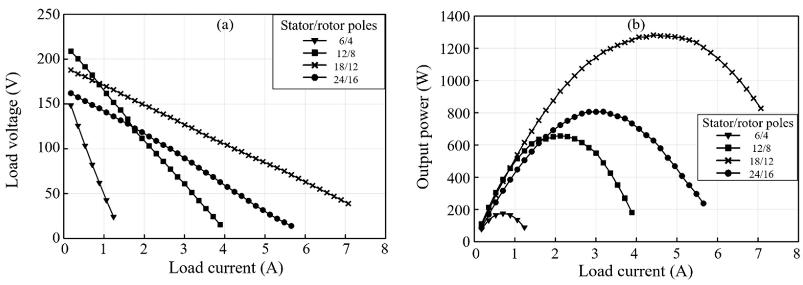
3.4. Analysis of Output Voltage and Output Power

Under the load condition, the output voltage and output power of the proposed DSPMG that has the optimal value of split ratio and stator pole arc obtained from the previous section was analyzed. The phase output voltage and three-phase output power of the generator was characterized in the situation where the generator is supplying the load with various current magnitudes. As illustrated in Figure 14, it was found that the 18/12 and 24/16 poles structures could be operated at a significantly wider load current range than the other two structures. The 12/8 poles conventional structure could produce high-output voltage only at small-load currents. By considering the output power, the 24/16 poles structure could produce the highest output power at most load current values. Especially, the two proposed structures, namely the 18/12 and 24/16 poles structures, demonstrated a remarkably better output power than the conventional structure. In general, the output voltage of the electrical generator is supposed to be dropped with increasing load current due to an increase of current-induced magnetic flux. Our analysis found that the proposed 18/12 and 24/16 poles structures indicated the smaller voltage drop at higher load currents than those of the other structures. This is mainly due to the high equilibrium property of the structure. Particularly, the DSPMG having 18/12 poles was selected as the most optimal structure in this study. The maximum output power of 1.28 kW can be reached by this optimal structure, which is two times higher than the conventional structure. The great output voltage profile of this optimal structure also implies that it can be widely used in several applications. Moreover, the electromagnetic torque produced by an optimal structure was 18% improved from the conventional structure. Although the no-load EMF of the optimal structure was 12% lower than the conventional structure during a very light-load operation, this operating range was very narrow compared with the overall operation range. Thus, the proposed pole configuration design technique can significantly improve the performance of this particular DSPMG. Lastly, it is suggested that the multi-discipline robust design optimization as well as the experimental validation may be conducted in future research.

4. Conclusions

In this work, a design technique to improve the electromagnetic performance of DSPMG was proposed by an adjustment of pole configuration. The number of stator and rotor poles, split ratio, and the stator pole arc were proposedly adjusted in order to improve the electrical performance of the generator. Then, the output characteristics of DSPMG including the magnetic field distribution, magnetic flux linkage, EMF, harmonic, cogging torque, electromagnetic torque, output voltage and output power were analyzed by finite element simulations. A symmetrical property of all proposed machines was firstly verified through the magnetic field distribution. The results showed that the pole number, split ratio and stator pole arc indicated a strong impact on the generator output profiles. The proposed 18/12 and 24/16 poles structures could significantly improve the output profiles compared to the conventional structure. Moreover, the output profiles could be further improved by adjusting the optimal split ratio and stator pole arc. The output power of 1.28 kW can be reached by the proposed optimal 18/12 poles structure, which is two times higher than the conventional structure. Meanwhile, the optimal structure produced 18% higher electromagnetic torque than the conventional structure. Thus, the proposed technique can be utilized to improve the output power of the DSPMG.

Author Contributions

Conceptualization, W.S. and P.K.; methodology, W.S. and P.K.; software, W.S.; validation, W.S. and P.K.; formal analysis, W.S., P.S., V.L., S.K., A.S. and P.K.; investigation, P.K.; resources, P.K.; data curation, V.L.; writing—Original draft preparation, W.S.; writing—Review and editing, P.K.; visualization, P.S., S.K. and A.S.; supervision, P.K.; project administration, P.K.; funding acquisition, P.K. All authors have read and agreed to the published version of the manuscript.

Funding

This research was financially supported by the Thailand Research Fund [grant numbers MRG6180010] and The National Science and Technology Development Agency -Electricity Generating Authority of Thailand Co-funding [FDA-CO-2562-10257-TH].

Conflicts of Interest

The authors declare no conflict of interest.

References

  1. Wang, Y.; Niu, S.; Fu, W. Electromagnetic performance analysis of novel flux-regulatable permanent magnet machines for wide constant-power speed range operation. Energies 2015, 8, 13971–13984. [Google Scholar] [CrossRef] [Green Version]
  2. Chau, K.-T.; Chan, C.; Liu, C. Overview of permanent-magnet brushless drives for electric and hybrid electric vehicles. IEEE Trans. Ind. Electron. 2008, 55, 2246–2257. [Google Scholar] [CrossRef] [Green Version]
  3. Cheng, M.; Hua, W.; Zhang, J.; Zhao, W. Overview of stator-permanent magnet brushless machines. IEEE Trans. Ind. Electron. 2011, 58, 5087–5101. [Google Scholar] [CrossRef]
  4. Li, H.; Chen, Z. Overview of different wind generator systems and their comparisons. IET Renew. Power Gener. 2008, 2, 123–138. [Google Scholar] [CrossRef] [Green Version]
  5. Zhang, Z.; Yan, Y.; Tao, Y. A new topology of low speed doubly salient brushless dc generator for wind power generation. IEEE Trans. Magn. 2012, 48, 1227–1233. [Google Scholar] [CrossRef]
  6. Shao, L.; Hua, W.; Dai, N.; Tong, M.; Cheng, M. Mathematical modeling of a 12-phase flux-switching permanent-magnet machine for wind power generation. IEEE Trans. Ind. Electron. 2015, 63, 504–516. [Google Scholar] [CrossRef]
  7. Gao, Y.; Qu, R.; Li, D.; Li, J.; Zhou, G. Consequent-pole flux-reversal permanent-magnet machine for electric vehicle propulsion. IEEE Trans. Appl. Supercond. 2016, 26, 1–5. [Google Scholar] [CrossRef]
  8. Zhao, J.; Yan, Y.; Li, B.; Liu, X.D.; Chen, Z. Influence of different rotor teeth shapes on the performance of flux switching permanent magnet machines used for electric vehicles. Energies 2014, 7, 8056–8075. [Google Scholar] [CrossRef] [Green Version]
  9. Hua, W.; Zhang, G.; Cheng, M. Investigation and design of a high-power flux-switching permanent magnet machine for hybrid electric vehicles. IEEE Trans. Magn. 2015, 51, 1–5. [Google Scholar] [CrossRef]
  10. Chen, H.; Aït-Ahmed, N.; Machmoum, M.; Zaim, M.E.-H. Modeling and vector control of marine current energy conversion system based on doubly salient permanent magnet generator. IEEE Trans. Sustain. Energy 2015, 7, 409–418. [Google Scholar] [CrossRef]
  11. Zhu, S.; Cheng, M.; Dong, J.; Du, J. Core loss analysis and calculation of stator permanent-magnet machine considering dc-biased magnetic induction. IEEE Trans. Ind. Electron. 2014, 61, 5203–5212. [Google Scholar] [CrossRef]
  12. Chau, K.-T.; Sun, Q.; Fan, Y.; Cheng, M. Torque ripple minimization of doubly salient permanent-magnet motors. IEEE Trans. Energy Convers. 2005, 20, 352–358. [Google Scholar] [CrossRef] [Green Version]
  13. Xu, W.; He, M. Novel 6/7 stator/rotor hybrid excitation doubly salient permanent magnet machine. IEEE Trans. Magn. 2016, 52, 1–5. [Google Scholar] [CrossRef]
  14. Yu, L.; Zhang, Z.; Chen, Z.; Yan, Y. Analysis and verification of the doubly salient brushless DC generator for automobile auxiliary power unit application. IEEE Trans. Ind. Electron. 2014, 61, 6655–6663. [Google Scholar] [CrossRef]
  15. Wang, Y.; Zhang, Z.; Yu, L. Investigation of a variable-speed operating doubly salient brushless generator for automobile on-board generation application. IEEE Trans. Magn. 2015, 51, 1–4. [Google Scholar] [CrossRef]
  16. Gong, Y.; Chau, K.-T.; Jiang, J.; Yu, C.; Li, W. Design of doubly salient permanent magnet motors with minimum torque ripple. IEEE Trans. Magn. 2009, 45, 4704–4707. [Google Scholar] [CrossRef]
  17. Wu, Z.; Zhu, Z.Q.; Shi, J.T. Novel doubly salient permanent magnet machines with partitioned stator and iron pieces rotor. IEEE Trans. Magn. 2015, 51, 1–12. [Google Scholar] [CrossRef]
  18. Cheng, M.; Chau, K.-T.; Chan, C. Characteristics of a new doubly salient permanent magnet motor. IEEE Trans. Energy Convers. 2001, 16, 20–25. [Google Scholar] [CrossRef] [Green Version]
  19. Sriwannarat, W.; Khunkitti, P.; Janon, A.; Siritaratiwat, A. An improvement of magnetic flux linkage in electrical generator using the novel permanent magnet arrangement. Acta Phys. Pol. A 2018, 133, 642–644. [Google Scholar] [CrossRef]
  20. Bottesi, O.; Alberti, L.; Gyselinck, J.J.C.; Gyselinck, J. Finite element small-signal simulation of electromagnetic devices considering eddy currents in the laminations. IEEE Trans. Magn. 2017, 53, 1–8. [Google Scholar] [CrossRef]
  21. Fasolo, A.; Alberti, L.; Bianchi, N. Performance comparison between switching-flux and IPM machines with rare-earth and ferrite PMs. IEEE Trans. Ind. Appl. 2014, 50, 3708–3716. [Google Scholar] [CrossRef]
  22. Kumar, P.; Bottesi, O.; Calligaro, S.; Alberti, L.; Petrella, R. Self-adaptive high-frequency injection based sensorless control for interior permanent magnet synchronous motor drives. Energies 2019, 12, 3645. [Google Scholar] [CrossRef] [Green Version]
  23. Buticchi, G.; Gerada, D.; Alberti, L.; Galea, M.; Wheeler, P.; Bozhko, S.; Peresada, S.; Zhang, H.; Zhang, C.; Gerada, C. Challenges of the optimization of a high-speed induction machine for naval applications. Energies 2019, 12, 2431. [Google Scholar] [CrossRef] [Green Version]
  24. Sriwannarat, W.; Siritaratiwat, A.; Khunkitti, P. Structural design of partitioned stator doubly salient permanent magnet generator for power output improvement. Adv. Mater. Sci. Eng. 2019, 2019, 2189761. [Google Scholar] [CrossRef] [Green Version]
  25. He, M.; Xu, W.; Ye, C. Novel single-phase doubly salient permanent magnet machine with asymmetric stator poles. IEEE Trans. Magn. 2017, 53, 1–5. [Google Scholar] [CrossRef]
  26. Lounthavong, V.; Sriwannarat, W.; Siritaratiwat, A.; Khunkitti, P. Optimal stator design of doubly salient permanent magnet generator for enhancing the electromagnetic performance. Energies 2019, 12, 3201. [Google Scholar] [CrossRef] [Green Version]
  27. Cheng, M.; Chau, K.-T.; Chan, C. Design and analysis of a new doubly salient permanent magnet motor. IEEE Trans. Magn. 2001, 37, 3012–3020. [Google Scholar] [CrossRef] [Green Version]
Figure 1. Cross-sectional perspective of the doubly salient permanent magnet (DSPMG) with (a) 6/4, (b) conventional 12/8, (c) 18/12 and (d) 24/16 stator/rotor poles.
Energies 13 04588 g001
Figure 2. The magnetic field distribution at a no-load condition of the DSPMG with (a) 6/4, (b) conventional 12/8, (c) 18/12 and (d) 24/16 stator/rotor poles.
Energies 13 04588 g002
Figure 3. The open circuit phase flux linkage waveform of the DSPMG having different numbers of stator and rotor poles.
Energies 13 04588 g003
Figure 4. The phase EMF of the DSPMG with different numbers of stator and rotor poles indicating (a) waveforms and (b) harmonic profile.
Energies 13 04588 g004
Figure 5. (a) The cogging torque and (b) electromagnetic torque waveforms of the DSPMG with different numbers of stator and rotor poles.
Energies 13 04588 g005
Figure 6. Cross-sectional perspective of the DSPMG at optimal split ratio of (a) 6/4, (b) conventional 12/8, (c) 18/12 and (d) 24/16 stator/rotor poles.
Energies 13 04588 g006
Figure 7. The magnetic flux distribution at no-load condition of DSPMG with (a) 6/4, (b) 12/8, (c) 18/12 and (d) 24/16 stator/rotor poles at a suitable value of split ratio.
Energies 13 04588 g007
Figure 8. The maximum value of (a) open circuit phase flux linkage and (b) phase EMF of the DSPMG having different numbers of stator and rotor poles at various split ratios.
Energies 13 04588 g008
Figure 9. (a) The maximum cogging torque and (b) the average electromagnetic torque of the DSPMG with different numbers of stator and rotor poles at various split ratios.
Energies 13 04588 g009
Figure 10. Cross-sectional perspective of the DSPMG at optimal pole arc values of (a) 6/4, (b) conventional 12/8, (c) 18/12 and (d) 24/16 stator/rotor poles.
Energies 13 04588 g010
Figure 11. The magnetic flux distribution at no-load condition of DSPMG with (a) 6/4 (b) 12/8 (c) 18/12 and (d) 24/16 stator/rotor poles at a suitable value of stator pole arc.
Energies 13 04588 g011
Figure 12. The maximum value of (a) open circuit phase flux linkage and (b) phase EMF of the DSPMG having different numbers of stator and rotor poles at various stator pole arcs.
Energies 13 04588 g012
Figure 13. (a) The maximum cogging torque and (b) the average electromagnetic torque of the DSPMG with different numbers of stator and rotor poles at various stator pole arcs.
Energies 13 04588 g013
Figure 14. (a) Output voltage and (b) output power of the DSPMG with different numbers of stator and rotor poles at the optimal stator pole arc.
Energies 13 04588 g014
Table 1. The structural parameters of DSPMG.
Structural Parameters (Unit)Value
The Proposed 6/4 Poles StructureThe 12/8 Poles
Conventional Structure [26]
The Proposed 18/12 Poles StructureThe Proposed 24/16 Poles Structure
Stator pole number6121824
Rotor pole number481216
Outer diameter of rotor (mm)150
Inner diameter of rotor (mm)118
Air gap length (mm)0.45
Outer diameter of stator (mm)117.5
Inner diameter of stator (mm)42
Stator pole depth (mm)19.8
Rotor pole depth (mm)6
Stator pole arc (°)27.2212.728.085.88
Rotor pole arc (°)32.1815.049.536.93
Number of permanent magnets2468
Permanent magnet thickness (mm)12643
Split ratio0.78
Permanent magnet typeNd–Fe–B
Radius of winding coil (mm)0.56
Table 2. The number of winding turns of each DSPMG structure.
Stator/Rotor PolesWinding Turn (Turns)
6/4346
12/18572
18/12378
24/16374
Table 3. The number of winding turns of each DSPMG structure at stator various pole arcs.
Machine StructureMachine Parameters
The proposed 6/4 poles structureStator pole arc (degrees)27.2124.1120.1015.7611.21
Winding turn per phase (turn)346404456502544
The 12/8 poles conventional structureStator pole arc (degrees)12.72
Winding turn per phase (turn)572
The proposed 18/12 poles structureStator pole arc (degrees)8.086.153.96
Winding turn per phase (turn)378464545
The proposed 24/16 poles structureStator pole arc (degrees)5.883.861.66
Winding turn per phase (turn)374490598

