Abstract
For the problem of poor accuracy of the existing multi-rate simulation methods, this paper proposes a multi-rate real-time simulation method based on the Norton equivalent, compared with multi-rate simulation method based on the ideal source equivalent. After the Norton equivalence of the fast subsystem and the slow subsystem are established, they are solved simultaneously at the junction nodes. In order to reduce the amount of the simulation calculation, the Norton equivalent circuit is obtained by incremental calculation. The data interaction between the fast subsystem and the slow subsystem is realized by extrapolation method. For ensuring the real-time performance of the simulation, the method of the slow subsystem calculates ahead of the fast subsystem is given for the slow subsystem with a large amount of calculation. Finally, the AC/DC hybrid power system was simulated on the real-time simulation platform (FPGA-based Real-Time Digital Solver, FRTDS), and the simulation results were compared with the single-rate simulation, which verified the correctness and accuracy of the proposed method.
1. Introduction
China has built the world’s largest AC/DC hybrid power system with the highest voltage level, and the regional power grids have been interconnected through ultra-high voltage AC/DC transmission lines [1,2]. The control and protection systems play an important role in the safe and reliable operation of the AC/DC hybrid power system, and the real-time simulation technology based on hardware in the loop can be used to verify the correctness of the protection device action and the effectiveness of the control strategy [3,4].
Large-scale AC/DC hybrid power system contains a large number of power electronic devices. Compared with traditional AC power systems, these devices have a small time scale and their dynamic characteristics have a great impact on the safe and stable operation of the power system. In order to simulate power electronic devices more accurately, the simulation step size is required to be smaller and smaller [5]. This is a challenge for the simulation of the AC/DC hybrid power system. For improving the speed of the simulation, two aspects are generally considered: one is to reduce the amount of the simulation calculation, the other is to use the parallel calculation technology. Reference [6] proposed a multi-layer topology hybrid model of power electronic switching components, which allows the modeling of converter topologies with an arbitrary number of output voltage levels with only two diodes and controlled voltage and current sources. It greatly reduces the number of switching combinations and the size of the generated code, and improves the speed of the simulation calculation. Reference [7] proposed a GPU-based parallel matrix exponential algorithm method for large-scale power system electromagnetic transient simulation, which significantly improves the speed of the simulation calculation. However, the GPU cannot independently complete the process control and data scheduling in the simulation calculation process, so it needs to cooperate with the CPU to complete the simulation calculation [8]. The above methods are all single-rate electromagnetic transient simulation methods, ignoring the differences of the time scale of electric power equipment in power system. The selection of the simulation step size can only be based on the system with the smallest time scale of electric power equipment, which will cause a serious waste of computing resources [9].
In view of the above problems, scholars at home and abroad have proposed the concept of parallel multi-rate electromagnetic transient computing, and different simulation steps are adopted for different systems according to the time scale of electric power equipment in power systems [10,11,12]. Reference [13] proposed a multi-rate electromagnetic transient simulation method based on Latency technology, in which the external part of the subnet was modeled as an ideal source. The ideal source model could not guarantee that the node signals (voltage and current) on both sides of the interface were equal, reducing the simulation accuracy. Reference [14] proposed a node splitting interface (NSI) multi-rate parallel technology. It solves the state space equations of the fast and slow subnets simultaneously, avoiding data prediction and signal delay, and improving the simulation accuracy, but the method cannot be used for real-time simulation. The above multi-rate simulations are all offline simulations and cannot be used for hardware-in-the-loop experiments. Reference [15] proposed a multi-rate real-time simulation method based on a joint simulation platform of real-time digital simulator (RTDS) and field programmable gate array (FPGA). It uses the asynchronous interaction method that FPGA data transmission is appropriately earlier than RTDS data transmission, which reduces a certain communication delay. But the communication delay of data interaction between different platforms still exists, which causes the reduction of simulation accuracy. In [16], a multi-rate real-time simulation of MMC-HVDC grids based on FPGA is proposed. The MMC system is decoupled by the stubline, and each MMC valve is implemented on one FPGA. The time steps can be flexibly chosen to meet the requirement of the time constraints. However, using multiple FPGA blocks for the simulation calculation will not only cause the data synchronization problem and decrease the simulation accuracy, but also waste the hardware resources of FPGA.
For the problem of poor accuracy of the existing multi-rate simulation methods, this paper proposes a multi-rate real-time simulation method based on the Norton equivalent, compared with multi-rate simulation method based on the ideal source equivalent. After the Norton equivalence of the fast subsystem and the slow subsystem, they are solved simultaneously at the junction nodes. In order to reduce the amount of the simulation calculation, the Norton equivalent circuit is obtained by incremental calculation. The data interaction between the fast subsystem and the slow subsystem is realized by extrapolation method. Finally, the AC/DC hybrid power system was simulated on the real-time simulation platform (FRTDS), which verified the correctness and accuracy of the proposed method.
2. Multi-Rate Simulation Calculation Timing
In the AC/DC hybrid power system, the power electronic equipment with fast control characteristics and the AC large-scale power grid are intertwined in different time scale processes, which makes the operation and control characteristics of the AC/DC hybrid power system more complicated [17]. Therefore, in the simulation of the AC/DC hybrid power system, various time scale processes in the AC/DC hybrid power grid should be considered. The simulation must be able to simulate the fast electromagnetic transient process (time scale of a few microseconds) of power electronic equipment such as converters and static synchronous compensators. It is also necessary to be able to simulate the switching process of the converter valve of the DC power system and the electromagnetic transient process of the AC power system (time scale of tens of microseconds to hundreds of microseconds) [18,19]. When using a single simulation step to simulate an AC/DC hybrid power system, if the simulation step is too small, the amount of calculation that needs to be completed within a single step is too large to complete, and if the simulation step size is too large, the dynamic characteristics of the power electronic components cannot be simulated, which reduces the accuracy of the simulation. For balancing the accuracy and the scale of the simulation, the entire system is decoupled into multiple subsystems. According to the time scale of electric power equipments in the subsystem, different step sizes are used for simulation calculation, that is multi-rate simulation.
There are two types of multi-rate simulation calculation timing: the serial calculation timing and the parallel calculation timing. Figure 1 shows the serial calculation timing and the parallel calculation timing of the two subsystems. Among them, Subsystem 1 uses a larger simulation step size , and Subsystem 2 uses a smaller simulation step size , where ( is a positive integer).
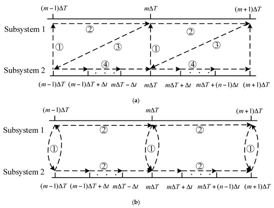
Figure 1.
The simulation calculation timing. (a) The serial calculation timing. (b) The parallel calculation timing.
In multi-rate simulation, the calculation tasks of the serial calculation timing need to be completed in sequence. In Figure 1a, ① at the time of , subsystem 2 transmits the data to subsystem 1 through the interface; ② Subsystem 1 carries out the simulation calculation through the received data; ③ Subsystem 1 transfers the data to Subsystem 2 through the interface; ④ Subsystem 2 carries out the simulation calculation through the received data. In serial calculation, the calculation tasks ①, ② ③ and ④ need to be completed in sequence, which seriously affects the speed of the simulation calculation. Therefore, the serial calculation sequence can generally only be used for offline simulation, not for real-time simulation calculation.
The calculation task of the parallel calculation timing can be completed at the same time, which improves the calculation speed. In Figure 1b, ① at the time of , subsystem 1 and Subsystem 2 conduct data interaction; ② Subsystem 1 carries out the simulation calculation through the received data, while Subsystem 2 carries out n times of the simulation calculation through the received data. In Subsystem 2, the data required by the simulation calculation is not known and more prediction data is required, so the parallel multi-rate simulation accuracy is low. However, for ensuring the real-time nature of multi-rate simulation, only parallel calculation timing can be used.
3. Multi-Rate Real-Time Simulation Based on the Norton Equivalence
3.1. Multi-Rate Real-Time Simulation Method Based on the Ideal Source Equivalence
In the multi-rate real-time simulation of the power system, the inductance and capacitor elements can be equivalent to the ideal source and the system is decoupled into multiple independent subsystems by taking advantage of the fact that the inductance current and capacitance voltage in the circuit cannot be suddenly changed. For example, the circuit with inductance L is equivalent as shown in Figure 2.
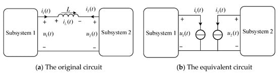
Figure 2.
The equivalent diagram of the inductance branch. is the current with inductance L. , is the voltage across the inductance L. At this time, the inductance L is equivalent to an ideal current source, and the system is decoupled into two independent subsystems, as shown in Figure 2b.
The relationship between current and voltage , with inductance L is as follows in Figure 2a:
Assume that Subsystem 1 uses a larger simulation step size , and Subsystem 2 uses a smaller simulation step size , where ( is a positive integer). By using the Euler method to difference Equation (1), then we can find that:
At the time of , Subsystem 1 and Subsystem 2 exchange and synchronize information. The voltage and of Subsystem 1 is sent to Subsystem 2, and the voltage (k = 1, 2, …, n) of Subsystem 2 is sent to Subsystem 1. Then perform data synchronization according to the substitution theorem, namely . After that, the calculation can be divided into two parallel tasks. The voltage and current of the equivalent current source of Subsystem 1 and Subsystem 2 are solved simultaneously.
For Subsystem 1, the current of the equivalent current source can be represented as:
According to the current of Subsystem 1, calculate the voltage of Subsystem 1. For subsystem 2, the current of the equivalent current source can be represented as:
where and are the voltage and current of the equivalent current source in Subsystem 2 and they are known. However, the current in Subsystem 1 is unknown, but it can be estimated by extrapolation. Then the extrapolation formula is:
According to the current of Subsystem 2, calculate the voltage of Subsystem 2. After that, the simulation of the next moment will continue. Similarly, the calculation process of multi-rate simulation method with capacitor C can be obtained. The multi-rate simulation method based on the ideal source equivalence takes advantage of the fact that the state variables of the inductors and capacitors in the system cannot be changed suddenly, and they are equivalent to the ideal source model. Then, the whole system is decoupled by the substitution theorem. However, in the simulation calculation, the voltage and current of the ideal source are all predicted, so the accuracy of this method is very low. It is necessary that the capacitance and inductance in the circuit must be relatively large, otherwise it will cause the reduction of simulation accuracy and even the decoupling system will be unstable.
3.2. Multi-Rate Real-Time Simulation Method Based on the Norton Equivalence
For the problem of the accuracy with the ideal source equivalent method, the idea of the Norton equivalent is used to replace the ideal source equivalent. After the Norton equivalence of the fast subsystem and the slow subsystem, they are solved simultaneously at the junction nodes, and then the state variables in the subsystems are obtained.
There are two linear sources-containing subsystems. One subsystem has a small time scale, represented by the subscript f. The other subsystem has a larger time scale, represented by subscript s. The two subsystems are connected to each other through k nodes, as shown in Figure 3.
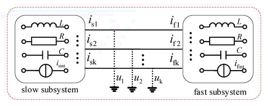
Figure 3.
The diagram of the power system. The input of the slow subsystem and the fast subsystem consists of two parts, the independent current source inside the subsystem, and the voltage or current at the interface. Where and are the current vectors at the subsystem interface; is the voltage vector at the subsystem interface; and are the independent current source vectors inside the subsystem.
The Norton equivalent is applied to the slow subsystem and the fast subsystem, and the simulation diagram based on the Norton equivalent is as shown in Figure 4.
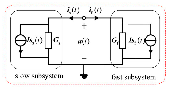
Figure 4.
The simulation diagram based on the Norton equivalent circuit.
Assume that the slow subsystem uses a larger simulation step size , and the fast subsystem uses a smaller simulation step size , where ( is a positive integer). The Norton equivalent circuit of the slow subsystem and the fast subsystem can be expressed as:
where, is(t) and if(t) are the current vectors at the Norton equivalent circuit interface; are the voltage vector at the Norton equivalent circuit interface; and Gf are the admittance
matrix of the Norton equivalent circuit, which are related to the state of the dynamic
elements in the slow subsystem and the fast subsystem. and are the current sources of the Norton equivalent circuit, and they are linear combinations of individual current sources and historical current sources.
Thus the current sources of the Norton equivalent circuit and can be represented as:
On the interface between the slow subsystem and the fast subsystem, there is:
From Equations (6), (7) and (10), we can find:
where Equation (11) is called the voltage equation of the interface nodes. From Equation (11), the voltage vector of the interface between the slow subsystem and the fast subsystem is obtained. After that, the state variables xs and xf in the slow subsystem and the fast subsystem can be solved.
When ( is a positive integer), the state of the dynamic elements in the two subsystems and the state variables and at the previous moment of the two subsystem are known. Then
the Norton equivalent is applied to the two subsystems, and calculate Gs, Iss(t), Gf and Isf(t). The voltage of the interface nodes can be obtained by the Equation (11). Finally, the state variables of the whole network are obtained.
When (k = 1, 2, …, n − 1), the state of the dynamic elements in the two subsystems and the state variables at the previous moment of the fast subsystem are known. However, the state variables of the slow subsystem are unknown. We can calculate it as followed by extrapolation method:
For the slow subsystem, the parameter matrix Gs corresponds to the
state of the dynamic elements at time of to , which spans two periods. To simplify the calculation, the state of the dynamic elements at time is used to solve the Norton equivalent of the slow subsystem, namely . When solving the current sources of the Norton
equivalent circuit, for reducing the amount of calculation, the current source is obtained by interpolation through and , instead of . The current source can be expressed as:
where the increment of equivalent current source can be represented as:
It is obvious that the current source of the Norton equivalent circuit only needs be calculated once in a large simulation step size, and the remaining current source can be obtained by the increment of equivalent current source. Therefore, does not need to use parameter matrix frequently calculate them, which greatly reduces the amount of calculation.
It can be seen from the previous analysis that the
solution of the voltage equation of the interface nodes requires the Norton
equivalent of the fast subsystem and the slow subsystem. Therefore, the
conductance and current source with the Norton equivalent of the slow subsystem
need to be sent to the fast subsystem to solve the voltage of the interface
nodes. After the voltage of the interface nodes is solved, it needs to be sent
to the slow subsystem to solve the internal state variables. When t = mΔT, summarizing the
above solution process, the process of the multi-rate real-time simulation
method based on the Norton equivalent is as follows:
- (1)
- Calculate the Norton equivalent circuit of the slow subsystem and the fast subsystem at the kth (k = 0, 1, 2, …, n − 1) period:
- (2)
- According to , , and , write the voltage equation of the interface nodes:
- (3)
- Solve the voltage equation of the interface nodes to get the voltage of the interface nodes
- (4)
- According to , the state variable xf(t + kΔt) of the fast subsystem can be obtained, and the state variable xs(t) of the slow subsystem can also be obtained.
3.3. The Data Interaction of Multi-Rate Real-Time Simulation
For hardware-in-the-loop simulation, all calculations of a
step size must be completed within the specified time. Otherwise, the real-time
performance of the simulation cannot be guaranteed. In the multi-rate real-time
simulation method based on the Norton equivalent, the Norton equivalent circuit
parameters of the slow subsystem and the fast subsystem are used to solve the
voltage of interface nodes. However, compared with the fast subsystem, there
are many nodes in the slow subsystem. The calculation amount of solving the
Norton equivalent circuit is very large, and it is difficult to complete in a
small step size. Since the slow subsystem is the AC power system, it is not
very important for the moment of state change of the dynamic elements. In order
not to delay the solution of the voltage of interface nodes, the calculation of
the slow subsystem can be earlier than the fast subsystem. For the time ΔS of the earlier
solving the slow subsystem, it can be assumed that ΔS = 0.5ΔT. If the calculation
of the slow subsystem cannot be completed, we should gradually increase ΔS. Otherwise, gradually
decrease until the optimal ΔS is found.
It can be seen from Figure 5 that within a smaller simulation step size, the Norton equivalent circuit of the fast subsystem, the voltage of the interface nodes, and the state variables of the fast subsystem must be completed. The Norton equivalent circuit of the slow subsystem, the voltage of the interface nodes, and the state variables of the slow subsystem must be completed within a larger simulation step size. In each smaller simulation step size (except the node of the larger simulation step size), it is necessary to predict the Norton equivalent circuit parameters of the slow subsystem for the solution of the voltage of the interface nodes.
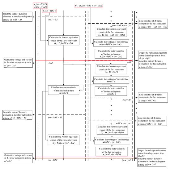
Figure 5.
The time of input and output and the logical relationship of calculation tasks with multi-rate real-time simulation method based on the Norton equivalent.
4. Case Study
4.1. Introduction to Real-Time Simulation Platform FRTDS
A field programmable gate array (FPGA) has a fully configurable parallel hardware structure, distributed memory structure and deep pipeline structure, and has the advantages of low cost and small size. These advantages make FPGA gradually participate in the real-time simulation calculation of power system as the main hardware [20]. Therefore, the Ministry of Education Key Laboratory of Smart Grids of Tianjin University has developed a real-time digital solver based on FPGA (FRTDS) [21,22,23]. It encapsulates commonly calculation formulas and functions in the microprocessor core, and converts simulation scripts into instructions that control the operation of the microprocessor core by self-developed compilation software. In order to improve the efficiency of writing simulation scripts, a graphical modeling tool for real-time simulation of power system has been developed. The power system database can be generated by using the graphical modeling tool, and then the FTRDS simulation script can be further generated, which further reduces the workload of the researchers. Users only need to generate power system database with graphical modeling tools, and do not need the capabilities of FPGA programming.
The UDP communication protocol is used between FRTDS and the host computer, and the function of the host computer is to download the simulation program and set up the simulation. IEC61850 is an international standard issued by the International Electrotechnical Commission and applied to substation communication network and system. Among the IEC61850 communication protocols, sampled value (SV) and generic object oriented substation event (GOOSE) adopt the peer-to-peer communication mode of point to multipoint, which are suitable for large data flow and high real-time requirements, so they are used between FRTDS and the real digital protection device. The Aurora communication protocol of Xilinx is a scalable lightweight link layer protocol for moving data between point-to-point serial links and it is used between FRTDS and the independently developed experimental controller. The FRTDS real-time simulation platform selects Xilinx’s Virtex-7 FPGA VC709 as the solver development board. The working frequency is 200 MHz. The compilation system, the script generation system and the operation monitoring system in the industrial PC are all developed by the QT C++ platform. The hardware-in-the-loop experimental platform based on FRTDS is shown in Figure 6.
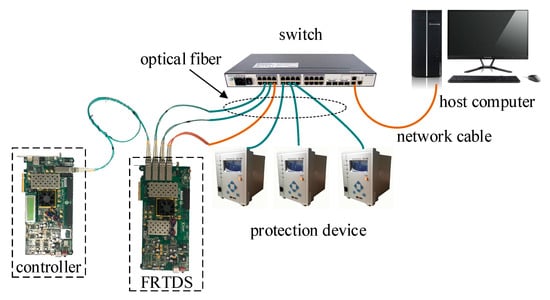
Figure 6.
The structure of hardware in the loop simulation system based on FRTDS.
4.2. Introduction to the Simulation System
The four-machine AC/DC hybrid system shown in Figure 7 is selected as the simulation example. The larger simulation step size of 50 μs is selected for the AC system, including generator, transformer, line and load, etc. The smaller simulation step size of 10 μs is selected for the DC system, including converter transformer, MMC converter station, DC line, DC filter, reactive power compensation capacitor, etc.
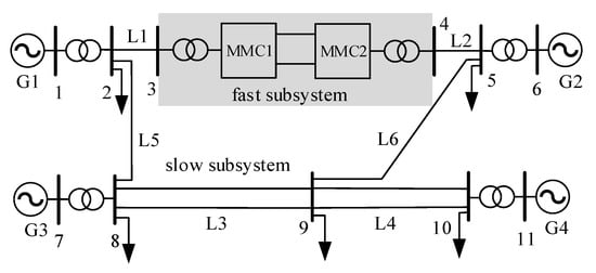
Figure 7.
The four-machine AC/DC hybrid system.
In the DC system, the converter is MMC with 77 level. The MMC is modulated by the nearest level modulation (NLM). The MMC1 is controlled by the constant active power and the constant reactive power. The MMC2 is controlled by the constant DC voltage and the constant reactive power. The relevant parameters of the DC system are shown in Table 1.

Table 1.
The relevant parameters of the DC system.
The parameters of the equipment in the AC system are shown in Table 2.
Table 2.
The parameters of the equipment in the AC system.
4.3. Simulation Result
For verifying the correctness and effectiveness of the multi-rate real-time simulation method, single-rate simulation method with the simulation step size of 10 μs (method 1) and two multi-rate simulation methods are carried out for the AC/DC hybrid system. Multi-rate real-time simulation method based on the ideal source equivalence is method 2 and multi-rate real-time simulation method based on the Norton equivalence is method 3.
(1) The verification of the simulation feasibility
For single-rate simulation, FRTDS provides 2000 maximum instruction clocks. For multi-rate simulation, the memory space is opened with the simulation step size of the slow subsystem. FRTDS provides 10,000 maximum instruction clocks. The software provided by FRTDS is used to write simulation scripts of single-rate and multi-rate methods respectively, and then the tasks are assigned. The list of instruction space occupied by the calculation task is shown in Table 3.
Table 3.
The comparison of single-rate and multi-rate instruction clocks.
As can be seen from Table 3, the instruction space occupied by the calculation task of method 1 has exceeded the allowable space, which cannot meet the requirements of real-time simulation. Both of the two multi-rate simulation methods can satisfy the real-time performance of simulation, but instruction clocks of method 3 are slightly higher than that of method 2.
(2) The verification of the simulation correctness
To prove the correctness of the simulation, three methods (method 1, 2 and 3) are used to simulate the AC/DC system. The inductance L used to decouple the AC/DC system in method 2 is 0.1H. The results of two multi-rate real-time simulation method (method 2 and 3) are compared with that of single-rate off-line simulation method (method 1) as follows.
(a) The three phase ground fault in converter bus 3
When t = 2 s, three phase metal grounding fault of converter bus 3 is set, and the fault is cleared after 0.2 s. The simulation results of the DC voltage and the AC current under single-rate and two multi-rate methods are shown in Figure 8.
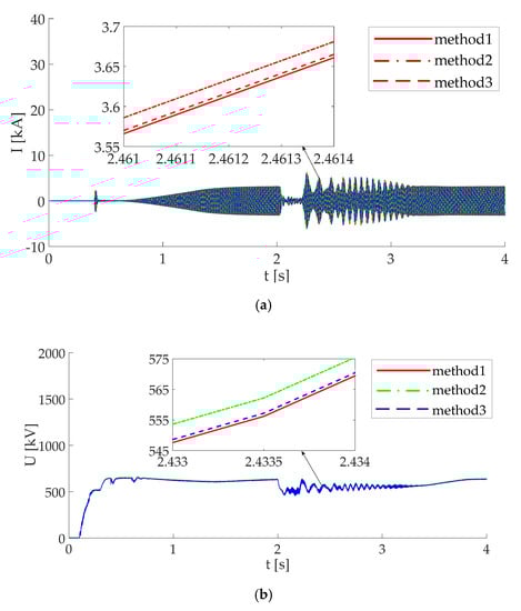
Figure 8.
The three phase ground fault in converter bus 3. (a) The AC current. (b) The DC voltage.
(b) The ground fault in DC line
When t = 2 s, the ground fault in DC line is set, and the fault is cleared after 0.2 s. The simulation results of the DC voltage and the AC current under single rate and two multi-rate methods are showed in Figure 9.
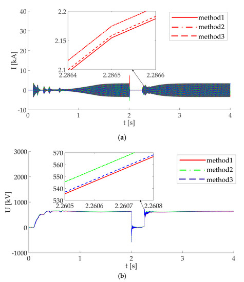
Figure 9.
The ground fault in DC line. (a) The AC current. (b) The DC voltage.
It can be seen from Figure 8 and Figure 9 that two multi rate real-time simulation methods (method 2 and method 3) have certain simulation accuracy, but the accuracy of multi rate real-time simulation method based on the Norton equivalence is higher than that based on the ideal source equivalence.
(3) The comparison of the accuracy of two multi-rate methods
Although the above simulation proves that the accuracy of method 3 is higher than that of method 2, they are not clear about the specific accuracy. In order to further study the accuracy of the simulation, the inductance used to decouple power system in method 2 is changed, and three methods are used to simulate the changed system. When the inductance L is 0.5H, 0.1H or 0.02H, the error between the simulation results of the two multi-rate simulation methods and the single rate simulation results is shown in Figure 10.
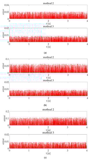
Figure 10.
The error of two multi-rate methods. (a) When the inductance L is 0.5H, the error of two multi-rate methods. (b) When the inductance L is 0.1H, the error of two multi-rate methods. (c) When the inductance L is 0.02H, the error of two multi-rate methods.
It can be seen that the maximum error of multi-rate simulation method based on the Norton equivalent is less than 1% and it has little changes from Figure 10a–c. However, with the decrease of inductance L, the maximum error of multi rate real-time simulation method based on the ideal source equivalence increases gradually. When the inductance L is 0.5H, the maximum error of method 2 is 2%. When the inductance L is 0.1H, the maximum error of method 2 is higher than 5%. When the inductance L is 0.02H, the maximum error of method 2 is up to 11%.
It can be concluded that the accuracy of the multi-rate real-time simulation method based on the Norton equivalence is higher than that based on the ideal source equivalence through the above pictures. Multi-rate real-time simulation method based on the ideal source equivalence takes the advantage of the characteristic that the inductance current and capacitance voltage in the circuit cannot be suddenly changed, and the whole system is decoupled by the method of substitution theorem. However, the accuracy of multi-rate real-time simulation method based on the ideal source equivalence is significantly affected by the inductance or capacitance used to decouple power system. There are limitations with the method and it can only be used in the circuits with the large inductance or capacitance. The conductance of the Norton equivalence circuit is the true value. It is only necessary to predict the current source of the Norton equivalent circuit of the slow system during the calculation of the fast system, so the accuracy is higher than multi-rate real-time simulation method based on the ideal source equivalent. Moreover, it can use any node to decouple a system without the need of the inductance or capacitance.
5. Conclusions
With the widespread application of MMC-based power electronic equipment in power system, multi-rate real-time simulation of the AC/DC hybrid power system has a broad application prospect in the field of power system simulation. However, the existing multi-rate simulation methods are not perfect and have poor accuracy.
This paper proposes a multi rate real-time simulation method based on the Norton equivalent, compared with multi-rate simulation method based on the ideal source equivalent. After the Norton equivalence of the fast subsystem and the slow subsystem, they are solved simultaneously at the junction nodes. In order to reduce the amount of simulation calculation, the Norton equivalent circuit is obtained by incremental calculation. The data interaction interface between the fast subsystem and the slow subsystem is realized by extrapolation method. For ensuring the real-time performance of the simulation, the method of that the slow subsystem calculates ahead of the fast subsystem is given for the slow subsystem with a large amount of calculation. Compared with the traditional multi-rate simulation methods, the paper proposed method improves the simulation accuracy without losing the simulation scale, and has important theoretical and practical significance to research on the real-time simulation of the AC/DC hybrid power system.
Author Contributions
Conceptualization, J.Z.; methodology, J.Z.; software, J.Z.; validation, J.Z.; formal analysis, J.Z.; investigation, J.Z.; resources, J.Z.; data curation, J.Z.; writing—original draft preparation, J.Z.; writing—review and editing, J.Z., B.Z.; visualization, J.Z.; supervision, B.Z.; project administration, B.Z.; funding acquisition, B.Z. All authors have read and agreed to the published version of the manuscript.
Funding
This research was funded by the National Natural Science Foundation of China, grant number 51477114.
Conflicts of Interest
The authors declare no conflict of interest.
References
- Liu, H.B.; Bian, D.; Sun, L.; Yun, Z.J.; Li, Y. Research on Electromechanical-Electromagnetic Transient Hybrid Simulation of AC/DC Hybrid System. Power Syst. Prot. Control 2019, 47, 39–47. [Google Scholar]
- Li, Y.L.; Zhang, X.; Li, Y.J.; Chen, Z.J.; Wu, M.Q. Current Situation and Challenges of Simulation Technology for AC/DC Hybrid Power Grid. Electric Power Constr. 2015, 36, 1–8. [Google Scholar]
- He, Y.Y.; Zheng, X.D.; Tai, N.L.; Hou, J.X.; Xu, J.; Huang, W.T. Overview of Modeling Methods of LCC-HVDC Converter in AC-DC Hybrid Power Grid. Proc. CSEE 2019, 39, 3119–3128. [Google Scholar]
- Dong, X.Z.; Tang, Y.; Bu, G.Q. Confronting Problem and Challenge of Large Scale AC-DC Hybrid Power Grid Operation. Proc. CSEE 2019, 39, 3107–3119. [Google Scholar]
- Zhang, M.X. Research on Real Time Multi Rate Joint Simulation Technology for Power Electronic System. Master’s Thesis, Beijing Institute of Technology, Beijing, China, 2016. [Google Scholar]
- Jost, A.; Niklaus, F.; Min, L. High Fidelity Real-Time Simulation of Multi-Level Converters. In Proceedings of the 2018 International Power Electronics Conference, Niigata, Japan, 20–24 May 2018; pp. 2199–2203. [Google Scholar]
- Zhao, J.L.; Liu, J.T.; Li, P. GPU Based Parallel Matrix Exponential Algorithm for Large Scale Power System Electromagnetic Transient Simulation. In Proceedings of the 2016 IEEE Innovative Smart Grid Technologies-Asia, Melbourne, Australia, 28 November–1 December 2016; pp. 110–114. [Google Scholar]
- Lu, F.S.; Song, J.Q.; Yin, F.K.; Zhang, L.L. Overview of CPU/GPU collaborative parallel computing research. Comput. Sci. 2011, 38, 5–9. [Google Scholar]
- Han, J.; Dong, Y.F.; Miao, S.H.; Liu, Y.L.; Liu, Z.W. MATE-based multi-rate electromagnetic transient parallel simulation method for power system sub-network. High Volt. Eng. 2019, 45, 1857–1865. [Google Scholar]
- Crow, M.L.; Chen, J.G. The method for simulation of power system dynamics. IEEE Trans. Power Syst. 1994, 9, 1684–1890. [Google Scholar] [CrossRef]
- Chen, J.G.; Crow, M.L. A variable partitioning strategy for the multi-rate method in power system. IEEE Trans. Power Syst. 2008, 23, 259–266. [Google Scholar] [CrossRef]
- Tang, Y. New Development of Research on Simulation and Modeling of Multi-time Scale Whole Process of AC/DC Power System. Power Syst. Technol. 2009, 33, 1–8. [Google Scholar]
- Moreira, F.A.; Marti, J.R. Latency techniques for time-domain power system transients simulation. IEEE Trans. Power Syst. 2005, 20, 246–253. [Google Scholar] [CrossRef]
- Mu, Q.; Liang, J.; Zhou, X.X.; Li, G.; Zhang, X. A Node Splitting Interface Algorithm for Multi-rate Parallel Simulation of DC Grids. CSEE J. Power Energy Syst. 2018, 4, 388–397. [Google Scholar] [CrossRef]
- Wang, X.; Zhang, B.D.; Chen, M. Multi-rate time Simulation Method Based on RTDS and FPGA Co-simulation Platform. Autom. Electr. Power Syst. 2016, 40, 144–150. [Google Scholar]
- Zhai, X.B.; Lin, C.; Gregoire, L.A. Multi-rate Real-time Simulation of Modular Multilevel Converter for HVDC Grids Application. In Proceedings of the IECON 2017—43rd Annual Conference of the IEEE Industrial Electronics Society, Beijing, China, 29 October–1 November 2017; pp. 1325–1330. [Google Scholar]
- Ou, K.J.; Li, P.F.; Guan, L.; Chai, Z.X.; Zhang, Y.J. Design and Research of Multi-time Scale Hybrid Real-Time Simulation System for AC and DC Power Grid. South. Power Syst. Technol. 2017, 11, 53–58, 64. [Google Scholar]
- Zhang, F.; Huang, W.C.; Li, C.D. MMC generalized fast simulation model suitable for multiple sub-module topologies. Electr. Power Autom. Equip. 2019, 39, 129–136, 143. [Google Scholar]
- Jost, A.; Niklaus, F. Sub-Cycle Average Models with Integrated Diodes for Real-Time Simulation of Power Converters. In Proceedings of the 2017 IEEE Southern Power Electronics Conference, Puerto Varas, Chile, 4–7 December 2017; pp. 6–11. [Google Scholar]
- Zhang, B.D.; Fu, S.W.; Jin, Z.; Hu, R.Z. A Novel FPGA Based Real-Time Simulator for Micro-Grids. Energies 2017, 8, 1239–1255. [Google Scholar] [CrossRef]
- Zhang, B.D.; Hu, R.Z.; Tu, S.J.; Zhang, J.; Jin, X.L.; Guan, Y.; Zhu, J.J. Modeling of Power System Simulation Based on FRTDS. Energies 2018, 11, 2749–2766. [Google Scholar] [CrossRef]
- Zhang, B.D.; Wang, Y.; Tu, S.J.; Jin, Z. FPGA-Based Real-Time Digital Solver for Electro-Mechanical Transient Simulation. Energies 2018, 11, 2650–2669. [Google Scholar] [CrossRef]
- Zhang, B.D.; Jin, X.L.; Tu, S.J.; Jin, Z.; Zhang, J. A new FPGA-based real-time digital solver for power system simulation. Energies 2019, 12, 4666. [Google Scholar] [CrossRef]


© 2020 by the authors. Licensee MDPI, Basel, Switzerland. This article is an open access article distributed under the terms and conditions of the Creative Commons Attribution (CC BY) license (http://creativecommons.org/licenses/by/4.0/).