1. Introduction
In last decade, bathroom panel radiators have become very common and are known as towel warmers. These panels are designed for bathrooms or kitchens and provide a space in which one or more towels are hung. Two types of towel warmers are shown in
Figure 1.
Many designs and many mounting methods can be found for these warmers. The latest trends have influenced the design process where in many cases the effectivity issue is lost. However, the effectivity of heat transfer, where the size and placement also play a significant role, cannot be estimated only from geometrical parameters; the surrounding area also has a significant role. It is not only the temperature and possible air flow, but also surrounding surfaces, parameters of the wall and distance to that wall. In addition, the heat transfer mechanism can be present in different forms, where for heating elements mainly the natural convection in form of buoyancy induced heat flow is present. Investigations of the buoyancy-induced heat flow around a heated cylinder can be categorized into three groups: (1) theoretical; (2) experimental; (3) computational (CFD) [
2,
3].
Theoretical solutions for natural convection, partially for laminar flow around a horizontally placed cylinder, are often less accurate than those for flat plates, due to the formation of a wake at the top of the cylinder, which affects the whole heat transfer process [
4,
5].
The first experiments in this field were focused on developing correlations between the effective heat transfer rate, uplift forces and properties of the surrounding fluid. Dimensionless quantities, the Nusselt (
Nu) and Rayleigh (
Ra) number, were used not only to simplify this correlating relationship, but also to quantify the two aforementioned problem characteristics [
6,
7]. Therefore, an array of cylinders, as for example in
Figure 2, that represents a heating source, should be described by using these criterial equations by using the geometrical parameters shown here.
2. Natural Convection from Cylindrical Surfaces
Natural convection as flow can also be classified in relation to boundary conditions, or whether the flow is bound to a surface or not [
4]. Where the bounding surface is absent, boundary free flow may occur, e.g., in the form of a plume or as buoyant jet flow. A plume is mostly formed where fluid flow is rising from a submerged heated object [
4,
5,
8]. This process and flow changes can be best observed via local Nusselt number. Corcione [
9] obtained the average Nusselt number for the
i-th cylinder in the vertical array by correlating the Rayleigh number Ra with the cylinder location relative to the center of bottom cylinder
x/
H. Corcione [
8] also obtained average Nusselt number of the whole tube-array Nua by correlating the Rayleigh number Ra, and the cylinder-spacing
S/
D, with a number (
N) of cylinders in the array. In his simulation results, Corcione [
9] did not detect the optimum heat transfer rates, which were found experimentally by the previous researchers at a given optimal values of tube spacing. He attributed this finding to the accidentally occurring disturbance which arises in the experiments, where this error cannot be accounted for exactly in his numerical simulation. The results are shown in
Table 1.
Ashjaee and Yousefi [
10] studied laminar natural convection from five aluminum horizontal isothermal cylinders of 10 mm diameter arranged in vertical arrays by carrying out experiments using a Mach-Zehnder interferometer. This experimental study covered the vertical cylinder vertical spacing range from 2 to 5 cylinder diameters (center-to-center) for vertical arrays. The Rayleigh number based on the cylinder diameter ranged between 1 × 10
3 and 3 × 10
3 in air. The authors obtained the average Nusselt number for the vertical array by correlating experimental data to the
Ra and
Py/d. The results are shown in
Table 1.
For small Rayleigh numbers, it is necessary to consider the boundary layer that forms around the cylinder [
11]. Although there are several studies on this subject, the scope of analytical, numerical and experimental data is wide. This range limitation in analytical and numerical methods exists because of used simplified boundary layer equations, boundary assumptions, and domain size solutions [
11,
12]. A detailed review of this problem can be found. For example, in Boetcher [
5,
12] there are a lot of discrepancies in experimental data for Prandtl number in the range of 0.6 to 0.8.
Another aspect that has to be considered, and for this study this is crucial, is the wall to cylinder distance. The placement of heat source and the distance to wall can affect simple free convection to change into coupled convection with conduction, but where conduction is unwanted. This process was described for example by Durst et al. [
6] and also by Lacroix and Joyeux [
7]. The main objective of this study is to examine under which conditions a simple cylinder or an array representing heating element and the main heat transfer process will become influenced by a wall. In this study, we present experimentally obtained data and a numerical model applied for this particular problem regarding the heating element’s distance to the wall.
3. Numerical Simulation
Flow velocities for natural convection are much smaller than velocities of forced convection. Thus, the convection transfer rates are also much smaller and more affected by various parameters.
In heating systems involving multimode heat transfer, natural convection forms the largest resistance to the process of heat transfer and therefore as a limitation has an important role in the process of design and later in performance of the system. In contrast, when it is desired to minimize heat transfer or to minimize operating costs, natural convection is preferred as the main heat transfer mechanism. In order to evaluate the buoyancy flow around the heated horizontal cylinders, a 2D computational model has been created using the FLUENT simulation software package.
Figure 3 shows the basic drawing of the problem geometry. The intent of this effort is to model heating element cylinders in terms of convective heat transfer and to create correlating equations for the whole tube-array. The approach taken for these models is a non-linear approximation for an array divided into four
S/D ranges and was detailed by Kapjor [
11], where the result is average Nusselt number for the whole cylinder array in relation to the changing tube-spacing parameter
S/D for a different bulk of cylinders in linear array. This is expressed as follows:
where
A,
B,
C and
E are coefficients for different
S/D ranges described in
Table 2.
The boundary layer and induced natural flow from heated horizontal cylinder starts to develop at the bottom, with increasing thickness along the surface, where a rising heat plume is formed at the top. We can assume that the local Nusselt number is higher at the bottom, and lower at the top of the cylinder if the flow remains laminar. However, the opposite is true in the case of a cold horizontal cylinder in warm medium, where the boundary layer and flow start to develop at the top of the cylinder and descending plume is formed at the bottom [
13,
14].
To quantify this phenomenon, a numerical model was set up, where the first step was creation of finite-volume mesh for each proposed geometrical configuration. For the best result and description of the effect of heat transfer problem, with possible wall restriction and its impact on heat transfer from the horizontal cylindrical surface, different geometrical ratios were selected, varying from 1.1 to 20.0. Because the description of the buoyancy-induced flow at each wall-to-cylinder distance requires an updated geometry and computational grid, parametric geometry files were used in conjunction with the aforementioned computational model. As a result, to simplify the creation of these geometry and mesh files, the modelling process started from the basic setup presented in
Figure 4, where the geometry for each selected wall-to-cylinder distance is constructed parametrically. To simplify the mesh creation procedure and to obtain a computational mesh that is as simple as possible, the rectangular geometry has areas with uniform regions.
Figure 4 also displays one example of how the pre-processing geometry was divided. Because of this, the simplification was also done by use of a cylindrical polar mesh in the proximity for each cylinder, and Cartesian mesh was used across the remainder of the integration domain. The integration domain is extended between rectangular boundaries or from the vertical wall up to rectangular boundary in defined distance from tube array, which is later represented as an imaginary boundary, or outer edge [
13].
We used the discretization technique, developed by Launder and Massey [
14], where the cylindrical polar grids and the Cartesian grid, independent one of another, overlap with no attempt at node-matching [
7]. Connection between them is provided only by a row of false nodes [
13], one for each overlapping mesh, located at their intersection, as shown in
Figure 4.
The numerical solution of heat transfer was advanced, with boundary conditions obtained from experiments. Single cylinder or cylinder array was placed in isothermal environmental chamber with thermocouples installed in the cylinder and in the wall. The scheme is shown in
Figure 5.
Measured data were used as boundary conditions and to adjust the simulation according to real conditions. In the first step, the result of the numerical solution was the temperature distribution around one cylinder. Here, in
Figure 6, as an example, the results of the numerical simulation made under steady state condition (
T∞ = 20 °C,
Ts = 40 °C) are given. In the process of natural convection, the boundary layer around the cylinder is very important and the temperature isotherms in the area around the cylinder surface are closer.
The fine mesh discretization scheme specifically used in the present study enabled us to solve the heat transfer process with the use of the numerical code and obtain the local and average Nusselt numbers for a single cylinder. The simulation focused on the heat transfer process at Rayleigh numbers of 10
3 and 10
4, where the present data are compared with the benchmark data by Saitoh [
15], as shown in
Table 3, where the results of Wang [
16], Kuehn and Goldstein [
17] are also reported.
These results confirmed the proposed numerical solution, where the difference between present solution and solutions made by other researchers was around 3%. This proposed model was later used to examine wall impact at heat transfer from the cylindrical surface. The heat flow is influenced by near placed walls, where the uplift forces are attached to the boundary. This is known as the Coanda Effect, which is named in honor of Henri Coanda, a Romanian aircraft engineer [
18,
19]. The Coanda Effect occurs mainly in situations where flowing fluid comes very close to a parallel surface [
20]. When this phenomenon occurs, the airflow itself is affected by the parallel surface, changes the expected route and flows along the surface, i.e., air clings to surfaces as it flows. The Coanda Effect is created by a pressure change at parallel surfaces, which allows the airflow to cling to the surface [
21,
22]. A significant role is played by the placement of cylindrical surface, heat source, or distance to the wall, which we have examined. Another aspect has to be mentioned. This is the practical use of this effect, where it is possible to guide the flow from the heat source with added surfaces or constructional features of the heat source.
4. Results
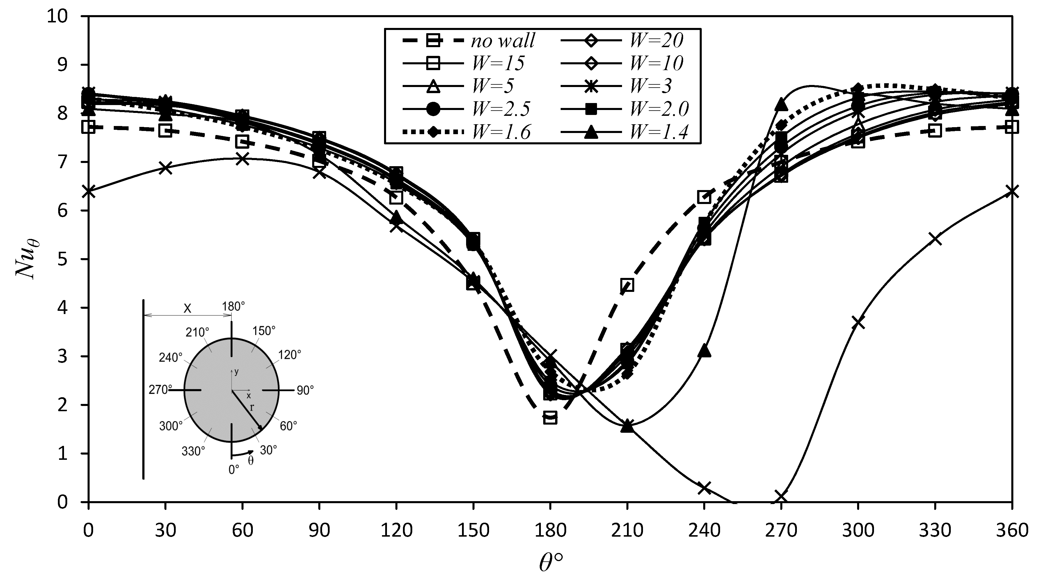
To observe the impact of the wall on the heat transfer process, we observed the most significant parameter, the Nusselt number. For prediction, we used the prepared model in the previous chapter. The results are illustrated in
Figure 7. The Nusselt number in cases without a wall is similar throughout the circle, with symmetrical attributes. For larger distances to the wall, according to the
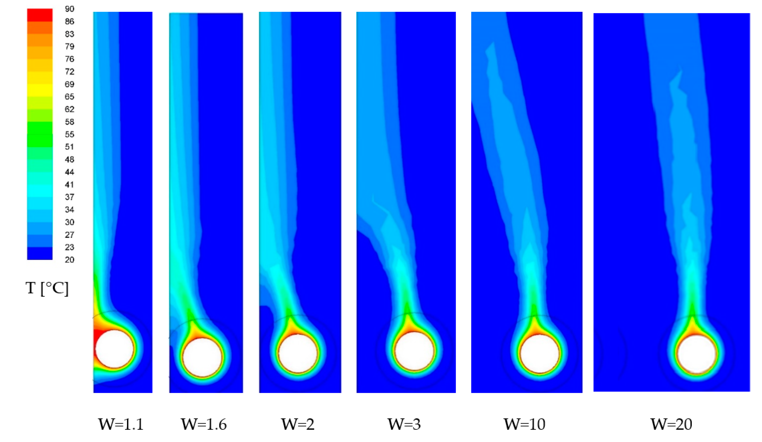
X/r ratio, the Nusselt number, and the flow are quite steady, without any unexpected exceptions. However, as the wall distance decreases, the steady symmetric flow loses its stability, yielding an asymmetric flow, which can be observed in the changing Nusselt number. The rising plume, shown in
Figure 8, with decreasing wall distance, can still be observed but is no longer symmetric with respect to the central axis. Thus, with decreasing wall distance we can see the developing of the well-known Coanda effect, which induces a withdrawal of the thermal plume towards the wall, depending on the initial conditions, as is mentioned in [
18].
The proposed model with applied boundary conditions from experiments was used for predicting a heat transfer mechanism from a cylindrical array. As shown in
Figure 8, in general, heated lighter fluid goes upward between the hot surface of the cylinders and the imaginary boundary at one side, and between the hot surface of the cylinders and the vertical wall until the cylinders get closer to the vertical wall at the other side. For the cases when the cylinder is a far from the vertical wall, the fluid moves straightforwardly, vertically upward. This is also mentioned by the authors in [
22]. As seen in the figures, where the cylinders are closer to the vertical wall, the fluid moves vertically upward in contact with the vertical wall.
As shown in
Figure 8, for
Ra = 3.5 × 10
4, when the cylinder moves closer to the wall, isotherms at the wall are lightly squeezed. When W is smaller than 1.6, the plume moves from the top of the cylinder, as shown
Figure 7 for the
θ = 210° to the side, or it is not formed.
For an array of cylinders, which represent the whole heating element, the numerical model was expanded. Results were compared to other studies in
Figure 9.
Figure 10 shows the numerical obtained, averaged Nusselt number of the array of cylinders (
Nua) as a function of wall-to-cylinder distance. Numerical results show that the average Nusselt number
Nua of the array increases when the cylinder keeps moving closer to the wall, but not in the same way as is the case with a single cylinder near a wall, as was investigated before. The main reason for this divergence is the center-to-center distance between each cylinder. As mentioned in the previous section and in [
10], the Nusselt number of the downstream cylinders increases for increasing separation distance. This phenomenon also occurs in the case of one side wall, as shown in
Figure 10, where the average Nusselt number has different characteristics with respect to the distance
S/D = from 2 to 10 for all investigated distances
W.
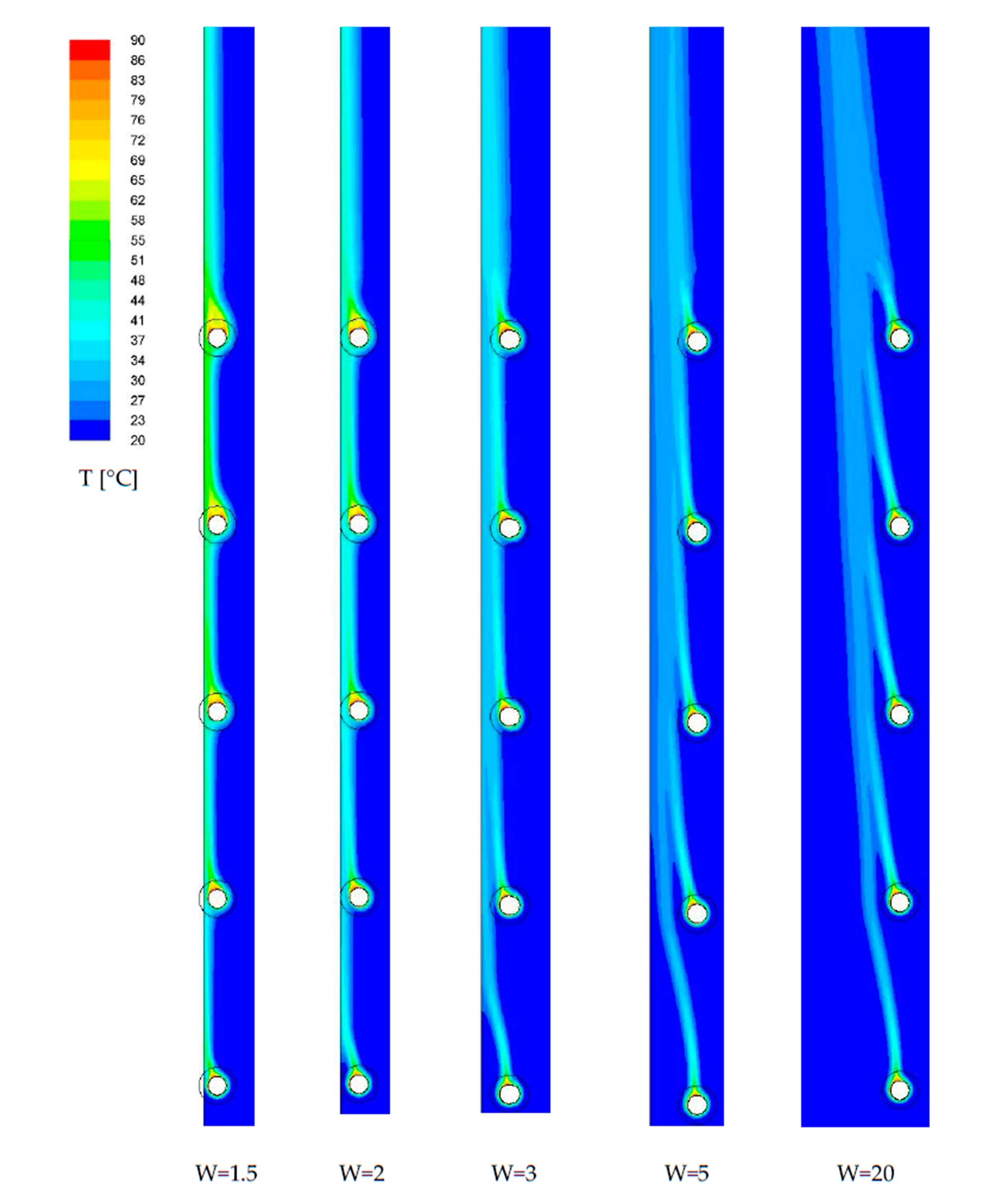
When the wall distance is decreased, the steady symmetric flow of 5 cylinders loses its stability earlier than a single cylinder, as shown in
Figure 11 by temperature fields. Comparing the temperature fields of single cylinder near a wall, the rising plume is markedly asymmetric at all W distances. The Coanda effect is considerably higher as in the case with a single cylinder, which leads to earlier deflection of the thermal plume over the cylinder array.
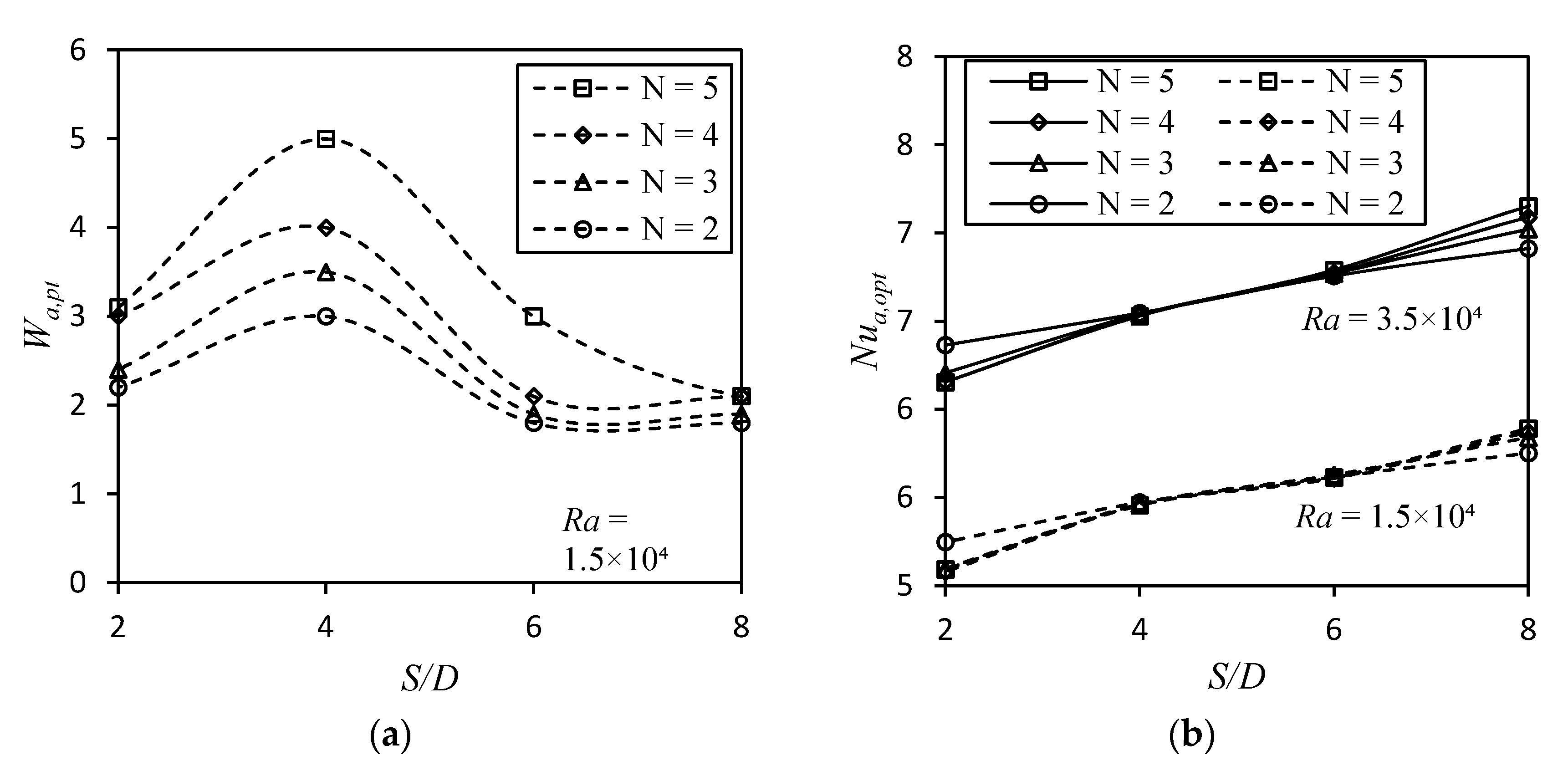
The optimal wall distance of an array of horizontal cylinders depends on the number of cylinders in the array,
S/D value, and Rayleigh number. The optimal wall spacing and the maximum average Nusselt numbers for the different array of horizontal cylinders (
N = 2 to 5), different
S/D values (
S/D = 2 to 10) and tree Rayleigh numbers (
Ra = 1.5 × 10
4, 2.9 × 10
4 and 3.5 × 10
4) are shown in
Figure 12.
The values from
Figure 12 show that there is a strong dependence on the
S/D parameter for an array of horizontal cylinders near a wall. The optimal wall-to-cylinder distance
Wa,opt changes significantly when the cylinder spacing is
S/D = 4. Thus, the optimal average Nusselt number is achieved markedly at highest
Wa,opt as a result of other
S/D spacing.
The optimal wall-to-cylinder distance
Wa,opt for an array of horizontal cylinders near a wall was also expressed as a function of the Rayleigh number and number of cylinders in the array by the following algebraic relations in
Table 4.
5. Discussion
Heat transfer from the oriented heat exchange areas of cylindrical surfaces is a complex process with many variables and different boundary conditions. A lot of research has been done in this area, with the aim of finding the relationship between heat output and boundary conditions. The relationship between heat transfer rate and character of flow around the cylinder is described by a criterion equation. This work focused on heat source placement and placement effect on average and local Nusselt number of the single horizontal cylinder in the free air, which were obtained from the experiment and from numerical simulation. Initially, the adjustment of the criterion equation was done according to previous work [
11] and new measurements. These results were compared to validate the proposed numerical model, and wall influence was studied. Consequently, heat transfer was analyzed using CFD with different boundary conditions to visualize the results. Nusselt number, which describes the nature of heat transfer, was observed at various Rayleigh numbers. It can be seen that Nusselt number decreases with
θ from the bottom surface. This was also observed in [
4] and [
17], as is compared in
Table 3. The flow forms a symmetrical plume around the tube. When the wall is present, because heating elements are installed near the wall, the plume loses symmetry. The Nusselt number, which describes the nature of heat transfer, changes, as is shown in
Figure 10. Overall, heat transfer is affected with decreasing wall to cylinder distance, which was also reported by [
4]. The decrease of Nusselt number, where the boundary layer thickness is increasing, which was mentioned by [
4,
18], causes a drop in heat transfer. The rising plume, shown in
Figure 11, with decreasing wall distance, can still be observed but is no longer symmetric with respect to the central axis. Thus, with decreasing wall distance we can see the development of the well-known Coanda effect, which induces a withdrawal of the thermal plume towards the wall, depending on the initial conditions, as is mentioned in [
17]. The results obtained from numerical simulation show that the Nusselt number increase with decreasing wall distance up to the point where the rate of heat transfer from the cylinder is at its maximum. However, at any distance to the wall and for any center to center distance, heat transfer at the bottom of cylinder remains approximately the same, which was also mentioned in [
23], and is minimally influenced by surrounding space, as is also mentioned in [
24].
6. Conclusions
Distance to wall plays a significant role, and in the case of a single cylinder, the Coanda effect strongly affects the heat transfer rate. Even at higher distances, the flow tends to stick to the nearest surface. For a cylinder array, the Nusselt number of the downstream cylinders increases with increasing distance from the wall. This phenomenon also occurs in the case with one side wall. When the wall distance is decreased, the steady symmetric flow loses its stability earlier than for the single cylinder. Comparing the temperature fields of a single cylinder near a wall, the rising plume is markedly asymmetric at all distances. The Coanda effect is considerably stronger for an array, as is the case with a single cylinder, which leads to earlier deflection of the thermal plume over the cylinder array. The optimal wall-to-cylinder distance Wa,opt for an array of horizontal cylinders near a wall was expressed as a function of the Rayleigh number and number of cylinders in the array by the algebraic relations. For some ranges, this distance can even be described in the form of linear equations, as is presented in this work.


