Article

Manufacturing Challenges of a Modular Transverse Flux Alternator for Aerospace

1
School of Engineering, Merz Court, Newcastle University, Newcastle Upon Tyne NE1 7RU, UK
2
Rolls—Royce Plc, The Derwent Building, 5000 Solihull Parkway, Birmingham B37 7YP, UK
*
Author to whom correspondence should be addressed.
Energies 2020, 13(16), 4275; https://doi.org/10.3390/en13164275
Submission received: 29 June 2020 / Revised: 12 August 2020 / Accepted: 14 August 2020 / Published: 18 August 2020
(This article belongs to the Special Issue Modular (Segmented) Electrical Machines)

Abstract

:
This paper presents the manufacturing challenges of a transverse flux alternator for an aerospace application. For fault tolerance, four independent isolated phases are required to deliver a specific power at low speeds, whilst at over speed, there is a strict limit on the short circuit current. A transverse flux machine (TFM) was selected due to its high inductance combined with the modular nature of separate phases lending itself to fault tolerance. The stator consists of pressed soft magnetic composite (SMC) segments. The authors explore the electromagnetic, mechanical, and assembly design challenges of the machine. It is shown that mechanical design aspects of the segments are of equal importance to the electromagnetic design and optimization. Simple design choices have allowed the same component to be used as all the stator segments, despite the requirement of a 90° electrical phase difference between phases and a tooth offset of 180° electrical within each phase.

Graphical Abstract

1. Introduction

Engine control electronics in civil aerospace require a dedicated fault tolerant power generation system to prevent a loss of aircraft power that might cause thrust control failure. Electrical, thermal, and mechanical isolations are required between phases, in addition to the ability to run short circuited indefinitely. Previously, it has been shown that this can be achieved through a segmented radial flux permanent magnet alternator [1,2]. Segmentation allowed for an improved assembly process and better coil fill factor compared to historical designs relying on magnetic slot wedges. The above fault tolerance requirements tends to result in the overall machine appearing oversized for its rated power.
A low-speed requirement, combined with mass and space constraints and the lack of a dedicated cooling system have led the designers to consider a transverse flux machine (TFM) in this paper. There are several advantages of TFM over traditional radial flux (PM) machines [3]. The competition for space between the electrical and magnetic loadings is mostly removed in TFMs [4]. High torque density is the main benefit of the transverse flux machines. By increasing the pole number and current loading, these machines achieve higher torques than more conventional radial flux machines [5,6]. However, TFMs are particularly suitable for low-speed applications where high torque is required [7]. Applications of TFM can include but is not limited to ships, buses, renewable energy systems as previously reported in the literature [8,9,10]. High torque dense TFMs with a higher number of rotor poles require high frequency electrical converters, implying that their speed is limited by the drive side [7]. However, this study deals with a more non-conventional application of transverse flux machines. The proposed machine in this study is a high speed, fault tolerant transverse flux alternator, employing modular (i.e., segmented) construction with some manufacturing challenges.
This class of machine is also known to have a high synchronous reactance, which for many applications causes the disadvantage of operating at a low power factor [11,12]. In this application, however, there is a fixed constraint on the allowable short circuit current at high speed, and so a high inductance is actually an advantage. In addition, the axial separation of phases makes TFMs inherently fault tolerant [13]. There may also be manufacturing advantages compared to the radial flux machines with non-overlapping windings that are usually proposed in aerospace [2]. One method of TFM assembly is the axial stacking of circumferential coils and toothed rings. A three-dimensional flux path in the toothed stator prevents the use of conventional flat laminations, and the method described here uses rings compressed from soft magnetic composite (SMC). As the rating of the SMC press required for component manufacture increases with component surface area, at large radii single component SMC rings become unpractical for many manufacturers. This paper hence considers the use of segmented SMC rings in TFMs. The resulting machine has both modular phases and a segmented stator. Modular construction is known to enable a flexible design and easy diversification of products [14], and it has been reported elsewhere that TFMs can take the advantage of this [15].
This study aims to explore assembly and manufacturing challenges of a high speed TFM for a civil aerospace application. The proposed machine has been optimized using genetic algorithm (GA) and a surface response was constituted with the results obtained through GA solutions. The alternator is investigated in terms of low speed power, cogging torque and fault tolerance. However, the authors are faced with design and assembly challenges in this machine as it includes a large number of parts. For instance, there are 32 stator segments in total and 96 rotor magnets in this machine, making it an interesting example in electrical machines under modular topologies, especially in an aerospace application.
The paper is structured as follows. Section 2 gives details of SMC and discusses its advantages and disadvantages on modular electric machines. Section 3 introduces the topology and includes initial design optimization methodology. Section 4 investigates cogging reduction techniques. Section 5 expands the machine to a modular four-phase machine. Section 6 details the design of the stator segments. Section 7 shows the overall layout of the alternator and conclusions of the study are given in the final section.

2. Modular Transverse Flux Machines Fabricated from Soft Magnetic Composites

Several advantages of TFM over traditional radial flux (PM) machines have been reported [3], such as avoiding the competition for space between the electrical and magnetic loading found in radial machines [4] and a high torque density. By increasing the pole number and current loading, these machines achieve higher torques than more conventional radial flux machines [5,6]. High speed TFMs with a high number of rotor poles will have a high electrical frequency and so their operation speed is potentially limited by the drive side [7]. In addition, iron loss is likely to be high. Hence, TFMs are generally thought to be suitable for low-speed high torque applications [7] and they have been proposed in automotive, marine, buses, and renewable energy applications [8,9,10,16].
SMC is composed of electrically insulated iron powder particles and is especially suitable for high frequency applications since eddy current losses are lower than that of electrical laminated steels at high frequencies [17,18]. Due to magnetic and thermal isotropy, SMC enables a remarkable degree of freedom on the design of three-dimensional magnetic flux electrical machines [19]. Novel topologies, such as TFM, axial flux machine, and modulated pole machines, have all been proposed using SMC cores [7,20,21].
There are several advantages of SMC core use in electrical machines. SMCs can improve power/torque density as they have relatively lower mass density than conventional electrical steels. In high frequency/speed applications, SMC cores give lower eddy current losses when compared to electrical laminations. It has also been suggested that manufacturing costs of electrical machines can be reduced by using SMC in high volume production [22]. However, lower permeability, higher hysteresis losses, and lower mechanical strength are known to be the main drawbacks in some grades of SMC compared to conventional laminated steels [19].
SMC cores are usually manufactured by compressing the iron powders in molds at very high pressures varying between 600 and 800 MPa. The molds must resist very high mechanical compressive stress and therefore, designing and building a mold (i.e., cavity) of ultra-high strength steels requires extra care and considerable cost. After the compaction process, heat treatment is usually needed to relieve the mechanical stress on the SMC components. There are no further manufacturing processes involved in building SMC components for electrical machines and the component is ready for assembly.
For prototype or low volume products, the cost of the press is likely to be prohibitive. An alternative is to use a pre pressed SMC block in a standard shape such as that shown in Figure 1. This will require further processing to obtain machine parts, such as wire eroding or milling. This however comes at the expense of potentially damaging the insulation on the SMC particles, and wire eroding of SMC blocks in particular is thought to create a conducting ‘skin’ on the surface and is not recommended.
In the literature, there are many examples of successful prototypes manufactured from the pre pressed block, either pure SMC [23,24] or some sort of material-hybrid meaning that they use both laminations and SMC components during assembly [21,25]. In this paper, the aim is to build a machine assembled in a manner that is representative of mass production and so bespoke pressed components have been designed. The diameter of the stator means it could not be compressed as a single component as the press required would be over 900 MPa press. Section 6 describes the process of segmenting the SMC components.

3. Machine Design

3.1. Machine Topology

A single pole pair of a single phase of the machine topology is shown in Figure 2. The rotor is flux concentrating with circumferentially magnetized permanent magnets separated by SMC pole pieces. The stator consists of toothed SMC rings surrounding a circumferential hoop coil. The sequential numbers given in Figure 2 can explain how the stator winding is linked with the rotor magnetic circuit. The permanent magnets (1) deliver flux into the SMC rotor pole (2). The flux concentrating pole delivers flux into a stator tooth (3) through the air gap. The flux moving into the stator core back (4) splits between the two teeth of the stator (5) in the bottom layer of stator core. Finally, the magnetic circuit is completed through a second air gap and the flux returns to an SMC pole (6).
The rotor poles and stator core are of Somaloy 700 HR 5P and a hoop coil with rectangular magnet wires is located between the stator’s top and bottom layers. A carbon fiber retaining sleeve is necessary as it is a high-speed machine with a rated speed of 15,000 rpm. The machine’s shaft and rotor hub must be of a non-magnetic material since the rotor core is not a part of the magnetic circuit.
Due to computational costs of 3D FE electromagnetic simulations, throughout this paper only one pole-pair has been modelled and with an even symmetric boundary condition on the model edges. The model is used to optimize all flux carrying components of the rotor and stator to achieve the machine’s power requirements within given dimensional constraints. The principal geometric variables of the TFM are tooth width, stator core back thickness, magnet height, coil volume, rotor outer diameter, and stator outer diameter. In terms of power delivery at the output, the motor constant ( K m ) defined as rotor outside radius divided by stator outside radius ( K m =   R r o t o r / R s t a t o r ) is of importance to optimize. The key machine specifications are tabulated in Table 1.
As given in Table 1, the alternator consists of four independent phases, all of which should satisfy low speed power of 40 Watts at 400 rpm. Due to fault tolerant requirements, the short circuit current at higher speeds is limited to 25 A rms. The high-speed power when the alternator is cascaded with a passive full-wave rectifier is minimum of 1200 Watts at 15,000 rpm. In order to achieve the given key specifications, one phase of the machine has been parametrized to be able to control the principal machine dimensions. This gives a degree of freedom in the selection of optimal machine geometry as depicted in Figure 3.

3.2. Initial Optimization

An objective function given in Equation (1) for 1/12 of the TFM phase with even periodic boundary was set to maximize the power at 400 rpm applying the dimensional constraints given in Table 1 to the parametric model shown in Figure 3. A genetic algorithm and response surface were used to create a quadratic equation relating the machine geometry to the output power at 400 rpm.
Maximize   { F o b j ( z )   = k P 400   rpm M a x P r e f }
where k = 1 is a weighting factor and F o b j ( z ) is a vector of optimization variables, subject to the constraints:
23.25   A I ^ s h o r t   c i r c u i t   35.5   A   at   15000   rpm 2400   mm 3   C o i l   v o l u m e   3500   mm 3 V ^ o c   15.625   V   where   V ^ o c   stands   for   peak   open   circuit   back   EMF
with variables
106   mm     Rotor   Outer   Diameter     116   mm 140   mm     Stator   Outer   Diameter     148   mm 2.5   mm     Magnet   thickness     6   mm 2.5   mm     A   half   of   tooth   width     4   mm 3.5   mm     Stator   Yoke   thickness     4.8   mm 26   N o   o f   T u r n s 41   ( Discrete   step   increase :   1 )
The final FE model with the highest output power is shown in Figure 4b. It is not an ideal design as it exhibits high cogging torque and was developed considering only one phase of the machine - ignoring mutual effects such as inductance variation, power factor change etc. A response surface was created in Minitab [26] with both linear and quadratic interaction terms of design variables in order to find the levels of variables that optimize a response. Pure GA convergence with a smaller search tolerance in 3D machine topologies is computationally very costly. Therefore, the selected successful GA solutions have been extended by a response surface design.
In Figure 5, effect of quadratic terms such as magnet height × tooth width, rotor outer diameter × stator outer diameter etc. on the alternator output power is shown for one phase of the alternator. The given contour plots in Figure 5 are of importance as it informs the designer regarding the machine performance in terms of geometrical variables. After finding out important design variables though a response surface to achieve the initial machine specifications, the parametric TFM model was further optimized considering the cogging torque and the machine is extended into a 4-phase TFM as will be discussed in the following sections. As with any machine that requires manufacture, and for segmental machines in particular, this initial optimization process is only one part of the design process. The proceeding sections consider the practical and operational constraints.

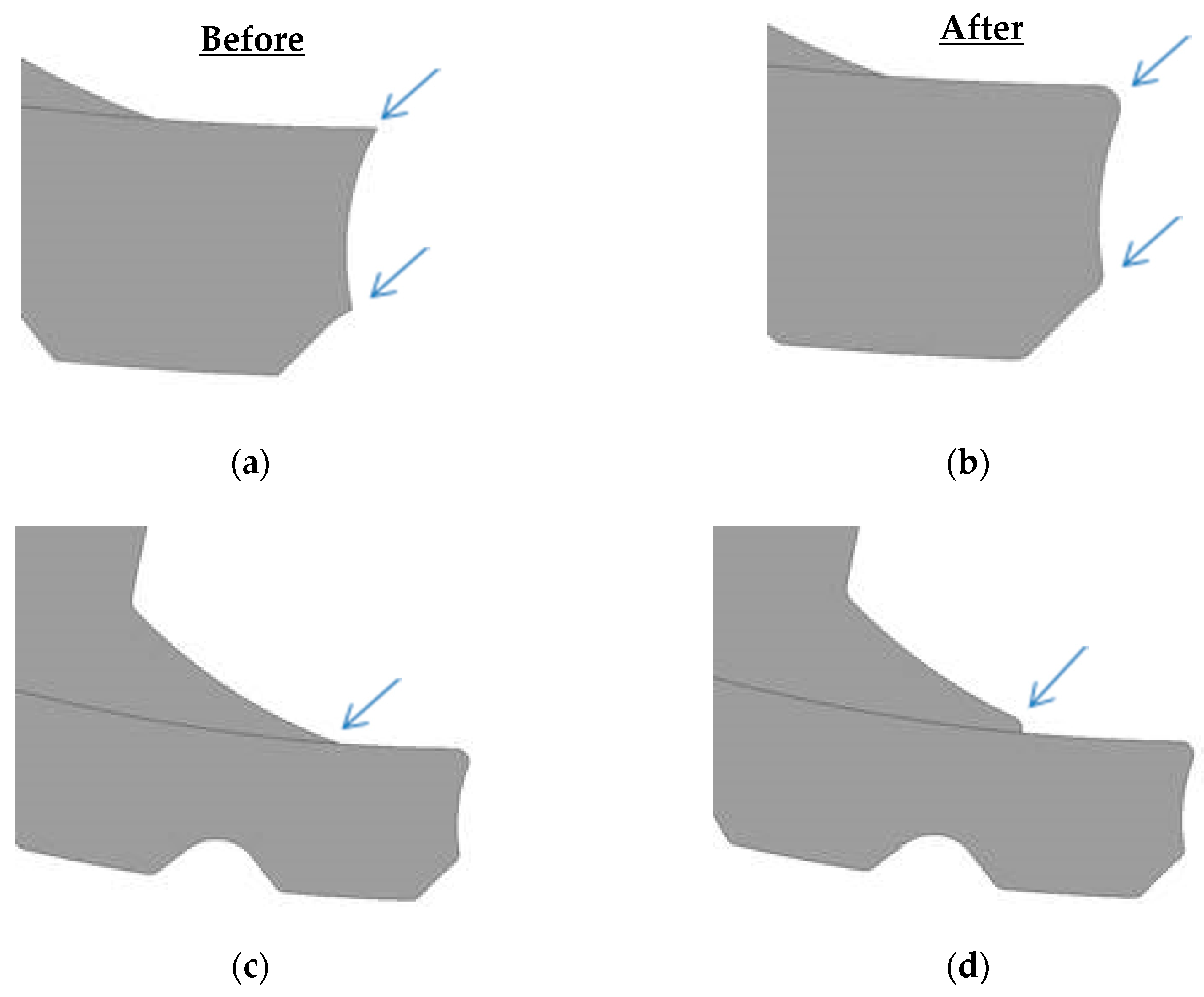
4. Cogging Torque Reduction

Maximizing output power in TFMs leads to a design with huge cogging torque and there are several methods suggested in the literature to reduce cogging torque in these machines [27,28]. Two techniques are considered in this section:
  • Tooth pitching (the teeth are shifted circumferentially that reduces the harmonics of back EMF and cogging torque; symmetrical and asymmetrical shifts can be applied).
  • Varying the ratio of flux concentrating pole width to stator tooth width (this approach reduces the cogging torque due to change in magnetic circuit in air gap region).

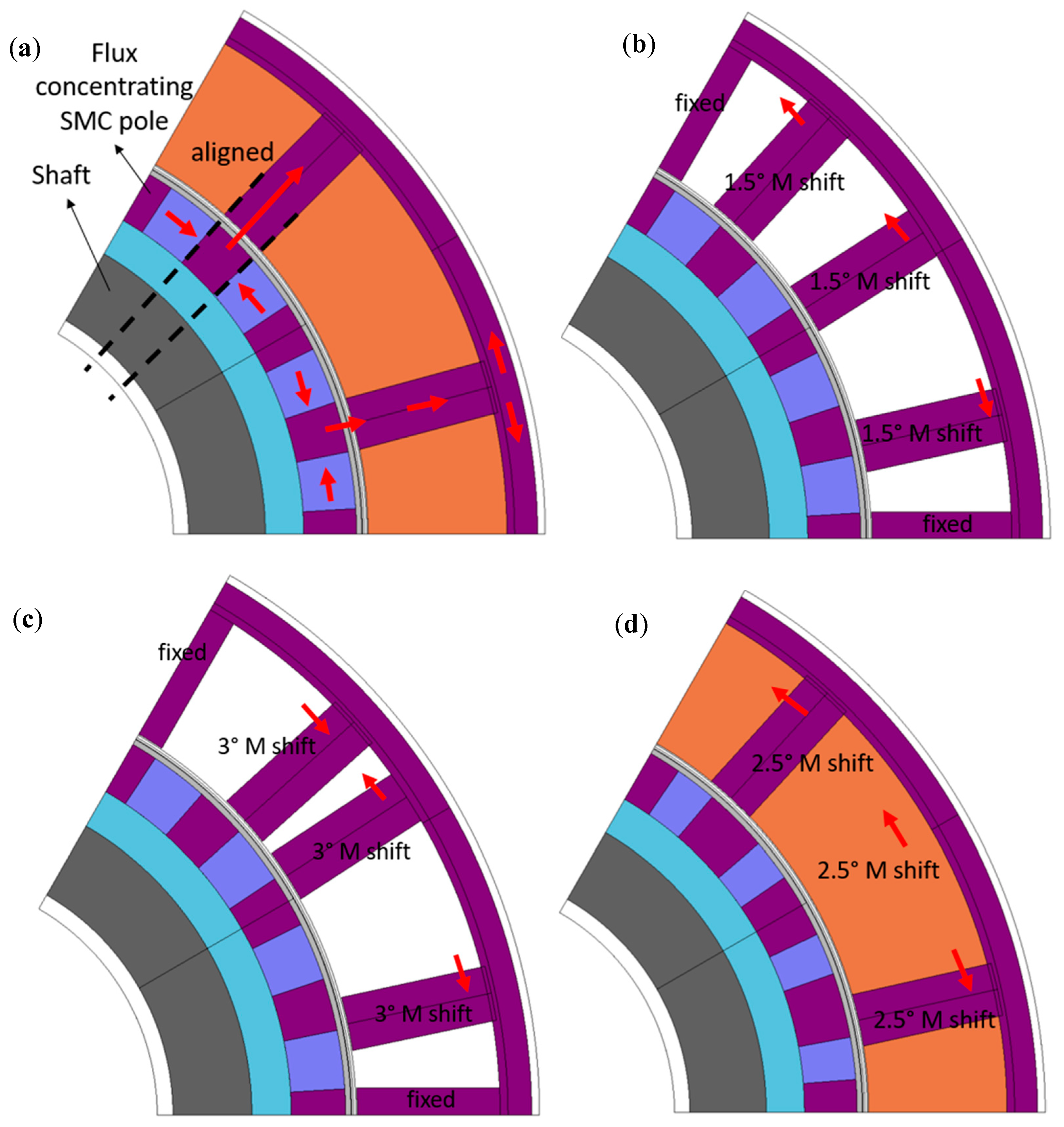
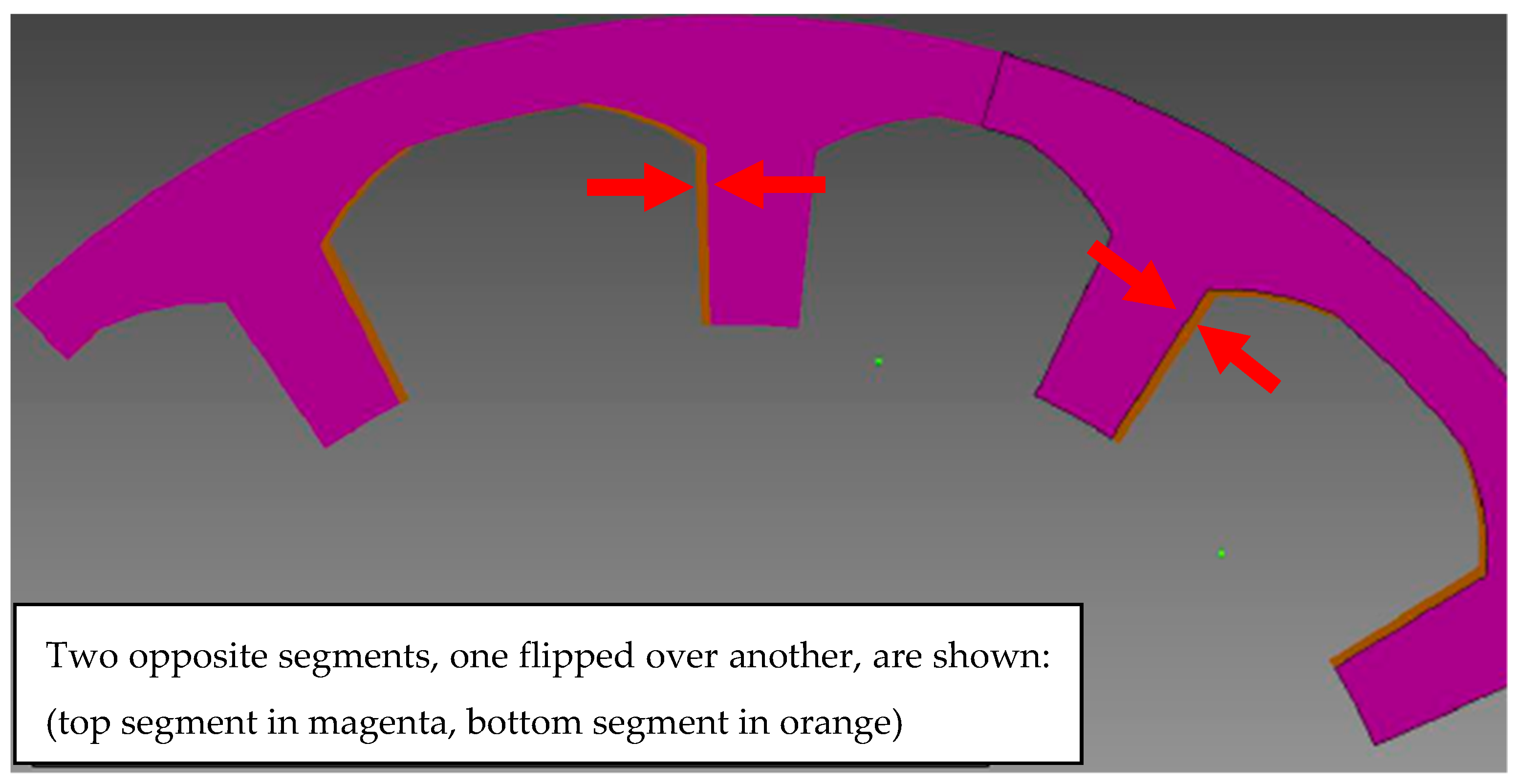
4.1. Asymmetrical Tooth Pitching

Tooth pitching in transverse flux machines is similar to coil pitching in radial flux machines. The authors investigated the effect of asymmetrical tooth pitching on the cogging torque reduction. Figure 6 shows the original geometry and the applied tooth pitching models. The cogging torque results for the single phase machine is given in Table 2.
For this application a four phase machine is required, and four axially positioned stator stacks in the complete machine would result in a higher cogging torque. Using a 90° electrical shift between the phases will, however, reduce the effect and the resulting cogging torque will not increase in the same proportion with the number of phases. 2.5° mechanical tooth pitching gives the lowest cogging torque but comes at the expense of a remarkable back EMF reduction of 34%.
From the manufacturing point of view, it is desirable to make all the stator segments identical so just one mold can be used. Asymmetrical tooth pitching given in Figure 6 requires more than one SMC pressing tool because if the stator is segmented, the segments in opposite layers will not be identical. Hence, a symmetry cannot be achieved in the stator segments. This phenomena is demonstrated in Figure 7 where the stator segments are mechanically aligned with each other. Therefore, a second cogging torque reduction method is applied in the proposed alternator as given in Section 4.2.

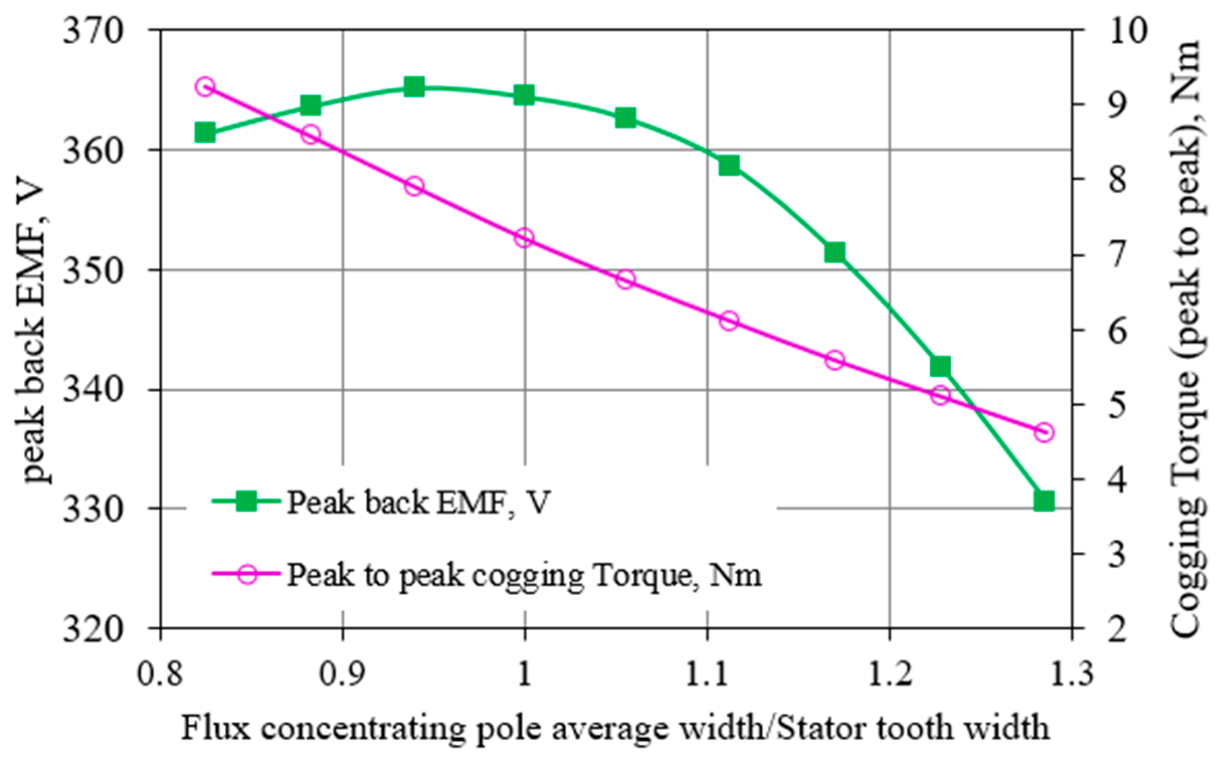
4.2. The Ratio of Flux Concentrating Pole Width to Stator Tooth Width

An alternative cogging torque reduction technique is to change the width of SMC rotor poles. This usually causes a reduction in back EMF as increasing the width of SMC rotor poles decreases the width of permanent magnets. In order to see this effect on both cogging torque and back EMF, 3D FE simulations have been performed. The results are given in Figure 8.
As shown in Figure 8, when the ratio between a rotor pole widths to stator tooth is equal to 1, back EMF reaches its maximum. By increasing this ratio (>1), the cogging torque is reduced significantly. It was chosen to be 1.28 for the optimized machine. In order to compensate the reduced back EMF, the magnet grade was changed from Recoma 30, a high temperature stable Samarium Cobalt magnet with Br = 1.12 T, to Recoma 33 (Br = 1.16 T). It is also worth mentioning that back EMF drop due to the cogging torque optimization was not considered to be an important design problem in this case since the optimized TFM satisfies the back EMF constraint, given in Section 3.1. Cogging torque reduction for the final machine in comparison to initial design is demonstrated in Figure 9. It can be seen that cogging torque for the four-phase TFM is significantly lower than a single phase TFM without an optimization study. It can be noted that the period of the cogging torque in an electrical cycle is doubled in the four phase machine. This is because the least common multiple of poles and slots is doubled for the four phase TFM.

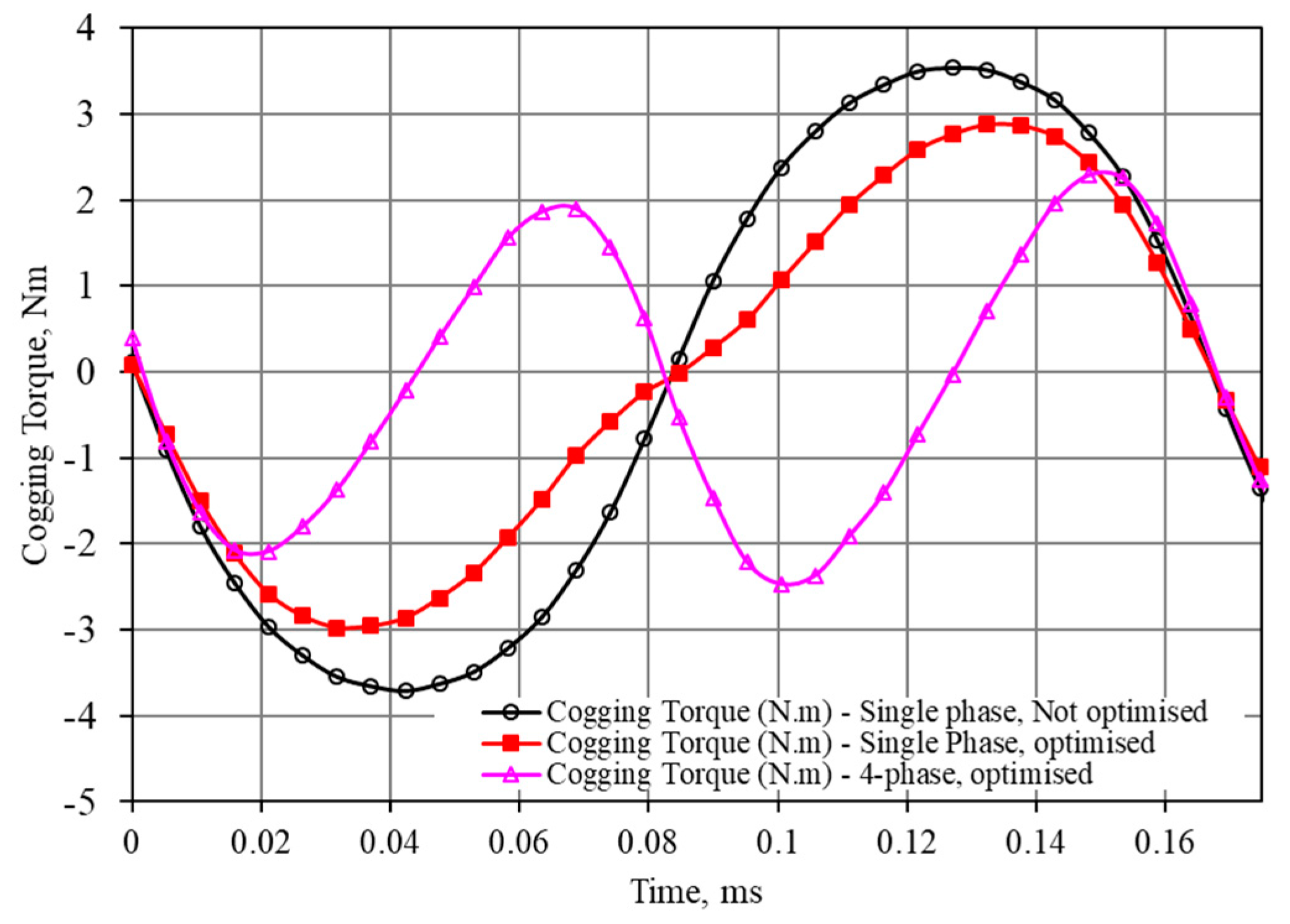
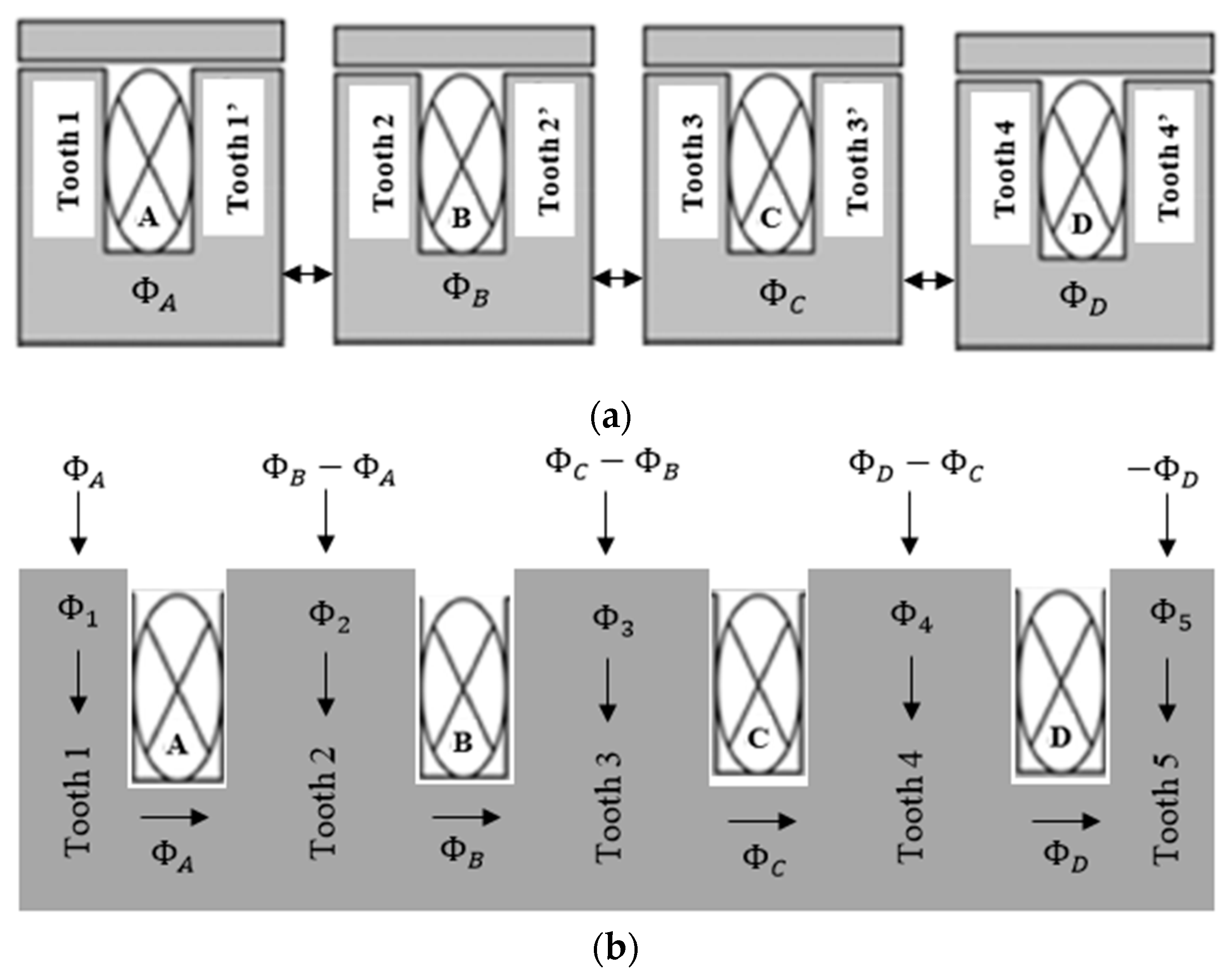
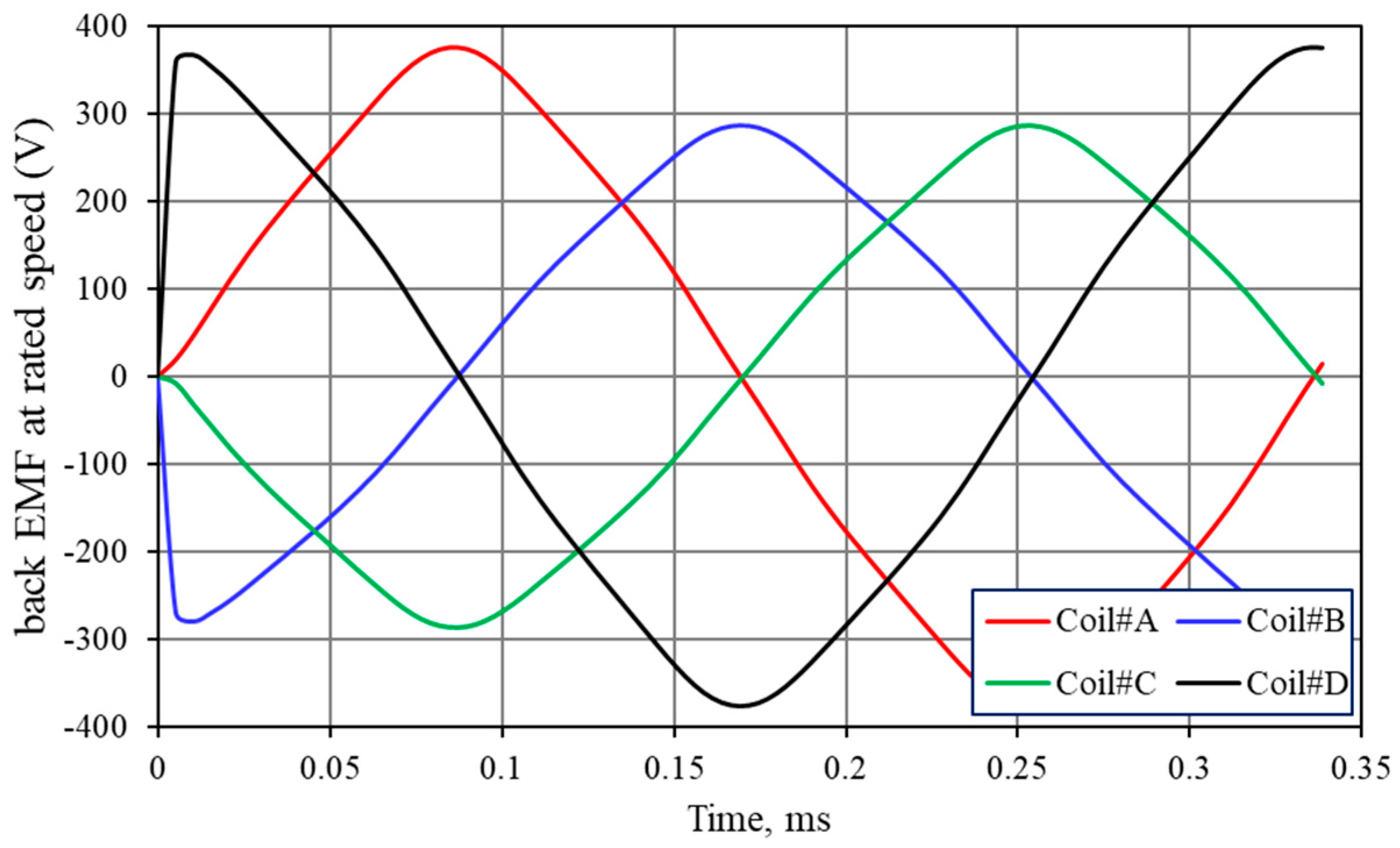
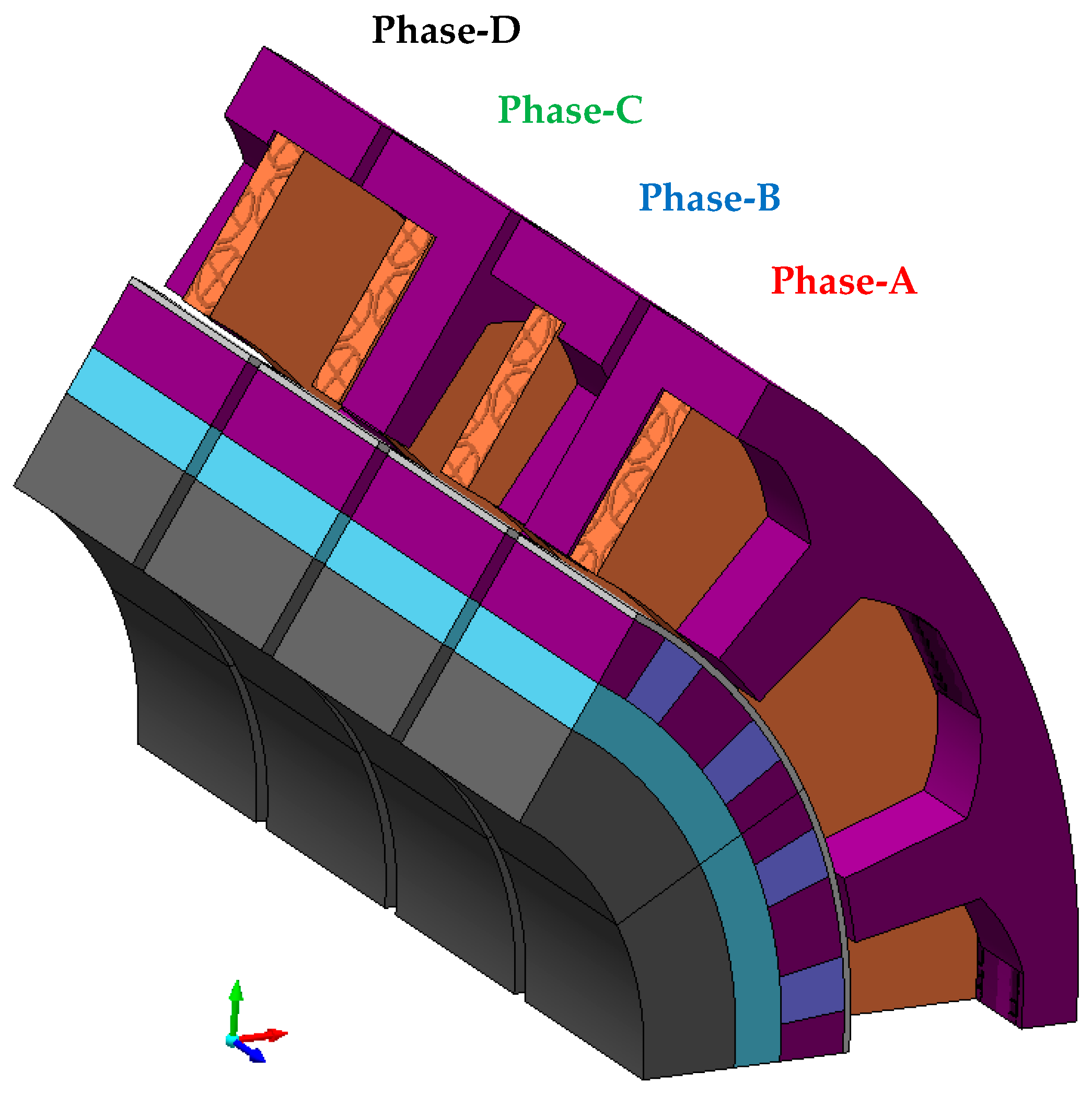
5. Four Phase Machine

Some mechanical modifications are required for the TFM stator to obtain a more mechanically robust design. Figure 10 shows the tapered stator teeth, a thicker stator yoke, and filleted tooth roots. From the electromagnetic point of view, these are not necessary to implement in such a machine topology as the authors have obtained less than 1% performance differences in the flux linkage, power, and back EMF results. However, the mechanical modifications are necessary in this case to physically produce the pressed components.
Axially stacked transverse flux machines with flux concentrating rotor poles can be designed as either physically separated modules or combined phase, where adjacent phases share teeth [7]. These concepts are shown in Figure 11 for a four phase machine. For the combined phase, shown in Figure 11b, the shared teeth need to be re-dimensioned as the magnetic loading on the central teeth increases in the combined-phase machine due to shared flux paths.
The best option for fault tolerance and high reliability is the separate-phase topology. In addition, the FEA results in Table 3 have shown that in a four phase system the separate-phase topology provides smoother back EMF (Figure 12) and less cogging torque.
In Figure 11a, central phases gives lower back EMFs as the number of turns for these phases are chosen to be 20, while the number of turns for end phases are 26 for the final design achieving the key performance targets. This is a balancing method for the machine short circuits at no-load condition. Ideally, short circuit currents must have same amplitude for a balanced three-phase machine. However, a four-phase TFM does not satisfy this condition and its short circuit currents at rated speed differ from each other. This is because the central phases (Phase-B and Phase-C) utilize higher mutual flux linkage in comparison to end phases. This causes higher phase inductance in Phase-B and Phase-C. Un-balanced power, back EMF, and flux linkage are common for the machine topologies where the machine phases are distributed axially rather than circumferentially.
The final 4-phase machine geometry is also depicted in Figure 13.

6. Assembly and Manufacturing Challenges of a Segmented Transverse Flux Alternator

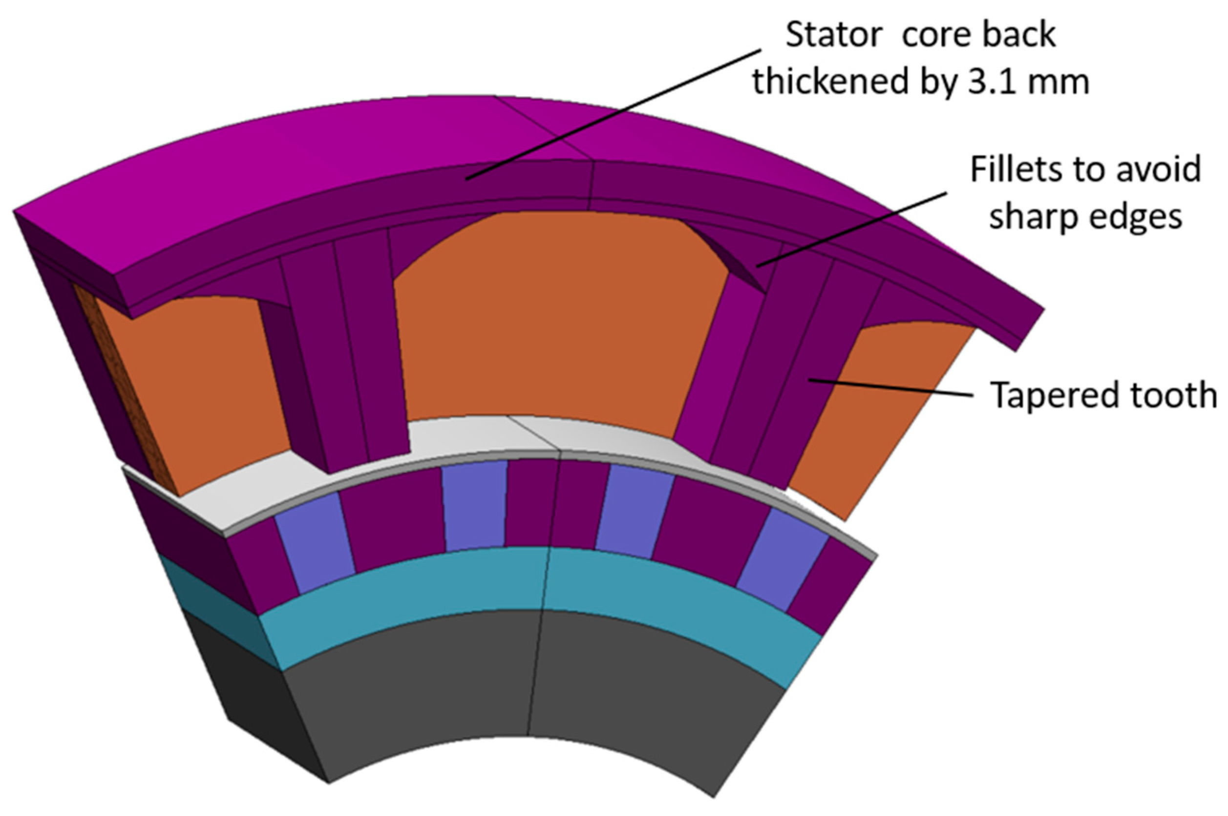
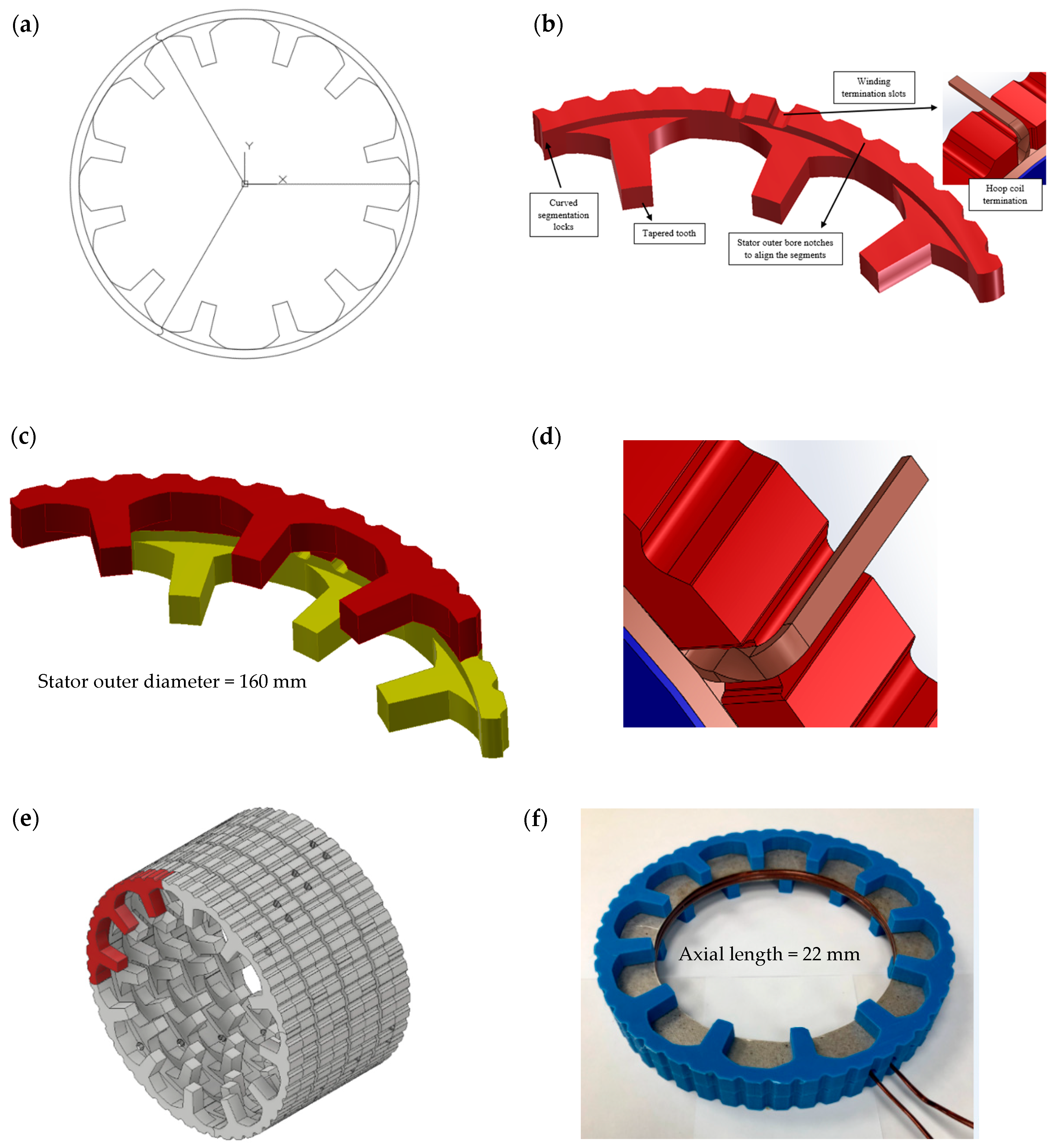
6.1. SMC Stator Segments

After electromagnetic design and optimization, mechanical design and assembly is the final part of the overall machine design process. Until now, it has been assumed that the stator teeth are a single component. However, compression of the SMC components includes many challenges and the geometrical dimensions dictate the component surface area which affects the required press force. For a machine of this radius, it was found that it was not possible to design a single component within the surface area constraints. The stator must hence be segmented as demonstrated in Figure 14. Segmentation is an important design consideration in terms of mechanical and electromagnetic aspects for a TFM. Circumferential segmentation of the stator does not significantly affect the magnetic flux flow as the modulated pole machines mostly complete the magnetic circuit via adjacent teeth pairs in opposite layers, 180° electrically apart from each other. The machine segments in opposite sides must have ignorable gap and this can be achieved through clamping the machine stator stacks inside the housing to ensure that the contact faces between the opposite segments do not cause any problems regarding electromagnetic performance of the machine. Nevertheless, the authors highlight that, due to low electrical loadings in this kind of aerospace alternator, the machine will experience relatively much lower surface forces in the magnetic air gap [1]. This usually results in lower displacement in the stator and hence low vibration and noise. The mechanical tolerances varying between 0.05 mm and 0.1 mm have been strictly considered in this study and the SMC segments will achieve tolerance figures as good as regular steel blocks in electrical machines.
In Figure 14a, the initial design is divided into three segments and circular lock features have been used to assemble the SMC segments. However, the distance between the furthest points in the three-segment machine is more than 130 mm, which again is problematic for SMC pressing, requiring a very large press with a rating of over 900 MPa. In order to make the design more feasible, the size of the TFM segments were reduced so that each ring now consists of four segments. Each phase requires two rings, and this is a four phase machine, so, in total, 32 identical SMC segments are required to form the alternator.
Figure 14b shows the final segment design, including a number of mechanical features required for machine assembly. For mechanical location, the outer perimeter requires the set of notches labelled in Figure 14b. They provide a lock feature between the stator core and housing and also enable an axial exit route for the winding terminals.
In Figure 14c, two opposite SMC segments are shown. The upper layer is shifted 15° mechanical with respect to the lower layer to achieve the 180° electrical phase shift required between the opposite layers. The rotor magnetic circuit with PMs are thus completed through stator stacks having a phase shift of one magnet pole as previously illustrated in Figure 2. The semi-circle grooves on the stator SMC segments are designed as given in Figure 14b. When the stator stacks come together, these semi-circles constitutes a full circular slot for end terminals of the hoop windings.
Figure 14d demonstrates the end terminal management. As shown, the wire cannot exit the slot without fouling on the inside surface of the slot. Therefore, the wire must be twisted to bring away from the inside of the slot into a more central position. The wire lead travels through the channels formed by semi-circular notches around the stator core. The terminals are insulated from the SMC stator core by using Kapton (by Dupont) polyimide tape.
The final mechanical design of the four-phase axially stacked TFM stator is depicted in Figure 14e. All 32 SMC stator segments in the complete machine are shown, with one highlighted for clarity. The terminal slots, centered by opposite segments of the stator, for windings can be seen around the stator outer diameter. The active length of the machine is 94 mm with 2-mm thermoplastic separators between the phases. A 3D printed stator segments and a hoop winding with 26 turns is demonstrated in Figure 14f. The winding slots for rectangular hoop coils have slot liners with a thickness of 0.5 mm resistant to a temperature up to 200 °C. It is also shown that 26 turns can be precisely fit into the TFM slots with a slot fill factor higher than 65%.
In Figure 15, sharp edges on the outer perimeter of the part lead to cracking of the carbide tooling, therefore small radii are required.
Further, the radii of 0.5 mm were added to avoid any sharp edges. Moreover, a flat and radius to each of the teeth were added as given in Figure 15c to avoid knife-edged tooling. After these geometrical modifications, the SMC parts are mechanically stable and easy to press. FEA modelling confirmed there is no noticeable effect of these geometrical modifications on the machine’s electromagnetic results.

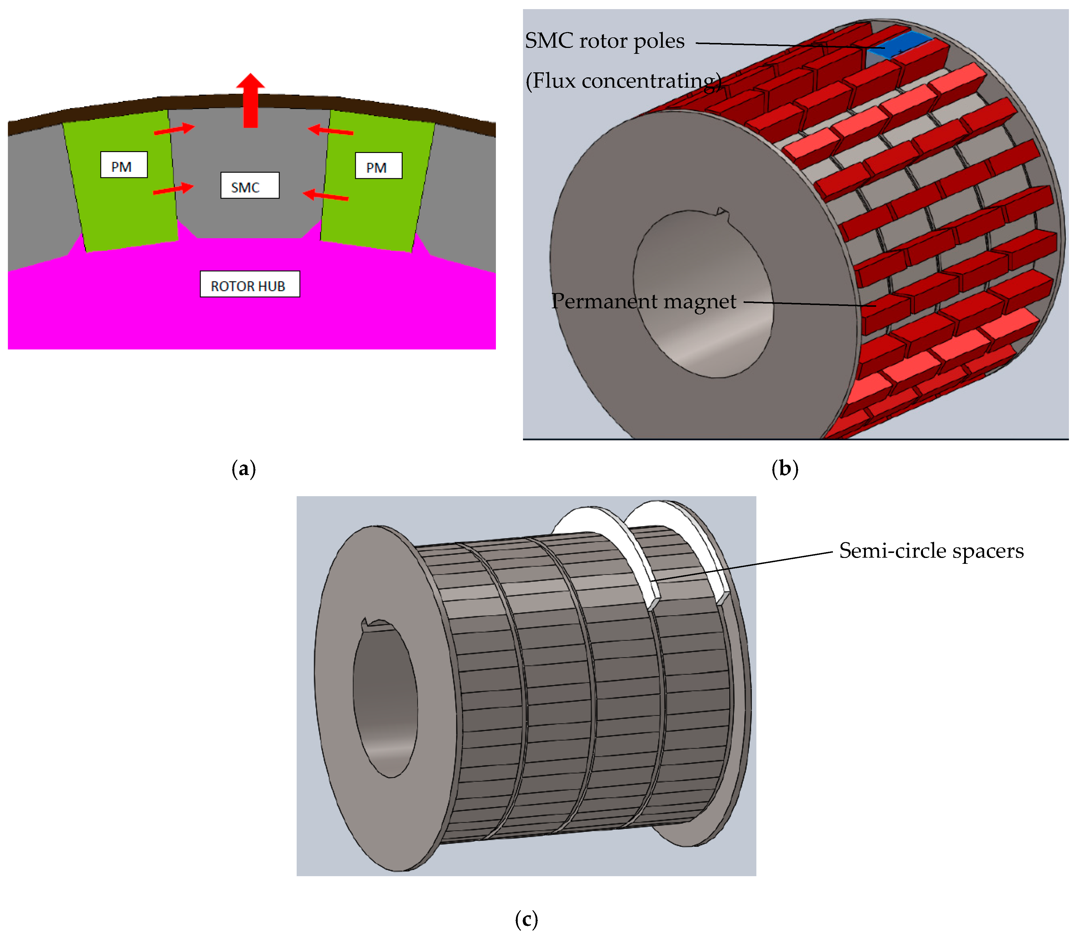
6.2. SMC Rotor Poles

The flux concentrating SMC rotor poles also require modification to make them suitable for pressing. To avoid any sharp edges 0.3 mm radii were added to all the corners. SMC rotor poles and permanent magnets (Samarium Cobalt, Recoma 33) have flat faces enabling them to be precisely located on the rotor’s polygonal outer perimeter as shown in Figure 16a. The rotor hub must be a non-magnetic material as it is not part of the magnetic circuit in rotor side. Titanium is chosen as a rotor hub due to its lightweight, mechanical and magnetic properties. A carbon fiber sleeve with a thickness of 0.7 mm ± 0.15 is sufficient to retain the rotor at higher speeds: 15,000 rpm. There are four rotor sections in total as depicted in Figure 1b. The authors propose ceramic spacers in Figure 16c with a thickness of 2 mm between the rotor sections as it is durable at high speeds in terms of thermal and mechanical aspects. The spacers must be a non-magnetic material and of a material with high electrical resistivity to reduce induced eddy currents and PM ohmic losses.

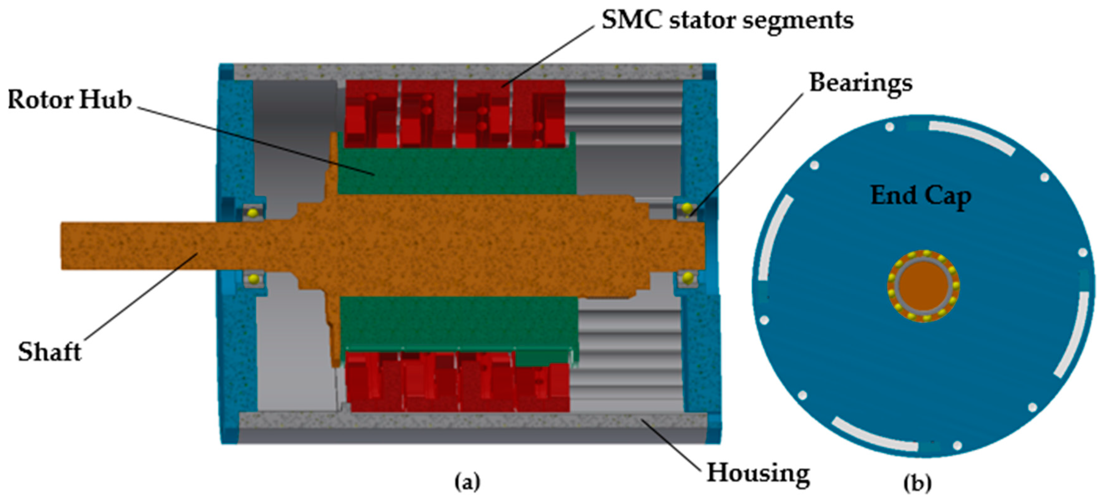
7. TFM Housing Design and Assembly

In Figure 17a, a half-section view of the complete assembly is shown. The TFM phase stacks are inserted into an aluminum housing with semi-circle notches in its inner perimeter. The winding terminals are reached through the channels formed by those notch features in the housing and SMC stator segments. The twisted magnet wires go through the channels horizontally and reach the machine’s end cap (Figure 17b). Thus, end terminal management can be achieved for the segmented TFM with hoop coils. The proposed machine also utilizes a tough grade EN24T (Smith Metal Ltd., Biggleswade, UK) stainless steel shaft possessing a keyway on it to lock the high speed shaft to the machine’s rotor.

8. Conclusions and Future Work

This paper focuses on the design, optimization, and manufacturing of a 24 pole/slot, four-single phase transverse flux alternator for an aerospace application. The machine short circuit currents at high speeds are limited during optimization to achieve fault tolerance. The machine was first optimized to achieve the required low speed power and then altered to reduce the cogging torque ripple. The total machine consists of four independent phase modules separated axially.
The proposed stator consists of a number of toothed rings, each consisting of four pressed SMC segments. The manufacturing constraints required to ensure a robust and economic machine have been described. It is shown that mechanical design aspects of the segments are of equal importance to the electromagnetic design and optimization. Segmentation of this type of machine is perhaps inevitable unless production volumes justify an investment in huge pressing tools. Simple design choices have allowed the same component to be used to all the stator segments, despite the requirement of 90° electrical between phases and a tooth offset of 180° electrical within each phase.
The authors will extend the study further in order to investigate the effect of SMC manufacturing approach on the machine losses enabling thermal characterization of the proposed machine that requires 300,000 h life expectancy as an aerospace alternator.

Author Contributions

Conceptualization, M.C.K., N.J.B., and S.T.; investigation, M.C.K. and N.J.B.; resources, N.J.B. and M.C.K.; supervision, N.J.B. and S.T.; writing—original draft, M.C.K.; funding acquisition, N.J.B. and S.T. All authors have read and agreed to the published version of the manuscript.

Funding

This work forms a part of the ENCASE project, funded by the Aerospace Technology Institute, administered by Innovate UK under application 91851-263262.

Acknowledgments

The authors gratefully acknowledge Owen Rolfe, Clive Hill and Nick Hayward from TT Electronics, Oliver Davis and Matthew Magee from SG Technologies, and finally David Terrington and Bjorn Gudmundsson from Arnold Magnetic Technologies for their contribution to the manufacture and winding of a prototype machine.

Conflicts of Interest

The authors declare no conflict of interest.

References

  1. Baker, N.J.; Smith, D.J.; Kulan, M.C.; Turvey, S. Design and performance of a segmented stator permanent magnet alternator for aerospace. In Proceedings of the IEEE Transactions on Energy Conversation, Glasgow, UK, 19–21 April 2018; pp. 40–48. [Google Scholar]
  2. Kulan, M.; Baker, N.; Turvey, S. Design and analysis of a fault tolerant permanent magnet alternator for aerospace. In Proceedings of the XIII International Conference on Electrical Machines (ICEM), Alexandroupoli, Greece, 3–6 September 2018; pp. 622–629. [Google Scholar]
  3. Wan, Z.; Ahmed, A.; Husain, I.; Muljadi, E. A novel transverse flux machine for vehicle traction aplications. In Proceedings of the IEEE Power & Energy Society General Meeting, Denver, CO, USA, 26–30 July 2015; pp. 1–5. [Google Scholar]
  4. Husband, S.; Hodge, C. The rolls-royce transverse flux motor development. In Proceedings of the IEEE International Electric Machines and Drives Conference, IEMDC’03, Madison, WI, USA, 1–4 June 2003; pp. 1435–1440. [Google Scholar]
  5. Weh, H. New permanent magnet excited synchronous machine with high efficiency at low speeds. In Proceedings of the International Conference on Electrical Machines, Pisa, Italy, 12–14 September 1988; pp. 35–40. [Google Scholar]
  6. Arshad, W.; Backstrom, T.; Sadarangani, C. Analytical design and analysis procedure for a transverse flux machine. In Proceedings of the IEMDC 2001, IEEE International Electric Machines and Drives Conference (Cat. No. 01EX485), Cambridge, MA, USA, 17–20 June 2001; pp. 115–121. [Google Scholar]
  7. Washington, J.G.; Glynn, J.A.; Baker, N.J.; Jack, A.G.; Mecrow, B.C.; Jensen, B.B.; Pennander, L.O.; Nord, G. Three-phase modulated pole machine topologies utilizing mutual flux paths. IEEE Trans. Energy Convers. 2012, 27, 507–515. [Google Scholar] [CrossRef] [Green Version]
  8. Mitcham, A. Transverse flux motors for electric propulsion of ships. In Proceedings of the Transverse Flux Motors for Electric Propulsion of Ships, London, UK, 18 June 1997. [Google Scholar]
  9. Schmidt, E. 3-D finite element analysis of the cogging torque of a transverse flux machine. IEEE Trans. Magn. 2005, 41, 1836–1839. [Google Scholar] [CrossRef]
  10. Dubois, M.R.J. Optimized Permanent Magnet Generator Topologies For Direct-Drive Wind Turbines. Ph.D. Thesis, Electrical Engineering, Mathematics and Computer Science, Delft University of Technology, Delft, The Netherlands, 24 January 2004. [Google Scholar]
  11. Svechkarenko, D.; Cosic, A.; Soulard, J.; Sadarangani, C. Transverse flux machines for sustainable development-road transportation and power generation. In Proceedings of the 7th International Conference on Power Electronics and Drive Systems, Bangkok, Thailand, 27–30 November 2007; pp. 1108–1114. [Google Scholar]
  12. Anglada, J.R.; Sharkh, S.M. An insight into torque production and power factor in transverse-flux machines. IEEE Trans. Ind. Appl. 2017, 53, 1971–1977. [Google Scholar] [CrossRef]
  13. El-Refaie, A.M. Fault-tolerant permanent magnet machines: A review. IET Electr. Power Appl. 2011, 5, 59–74. [Google Scholar] [CrossRef]
  14. Asan, U.; Polat, S.; Serdar, S. An integrated method for designing modular products. J. Manuf. Technol. Manag. 2004, 15, 29–49. [Google Scholar] [CrossRef]
  15. Szabó, L. Advancements in electrical machines design brought by the modular construction. In Proceedings of the X International Conference on Electrical Power Drive Systems (ICEPDS), Novocherkassk, Russia, 3–6 October 2018; pp. 1–6. [Google Scholar]
  16. Martinez-Ocaña, I.; Baker, N.J.; Mecrow, B.C.; Hilton, C.; Brockway, S. Transverse flux machines as an alternative to radial flux machines in an in-wheel motor. J. Eng. 2019, 2019, 3624–3628. [Google Scholar] [CrossRef]
  17. Zhang, B.; Epskamp, T.; Doppelbauer, M.; Gregor, M. A comparison of the transverse, axial and radial flux PM synchronous motors for electric vehicle. In Proceedings of the IEEE International Electric Vehicle Conference (IEVC), Florence, Italy, 17–19 December 2014; pp. 1–6. [Google Scholar]
  18. Jordan, S.; Baker, N. Air-cooled, high torque machines for aerospace applications. In Proceedings of the Air-Cooled, High Torque Machines for Aerospace Applications, Glasgow, UK, 19–21 April 2016. [Google Scholar]
  19. Liu, C.; Lei, G.; Wang, T.; Guo, Y.; Wang, Y.; Zhu, J. Comparative study of small electrical machines with soft magnetic composite cores. IEEE Trans. Ind. Electron. 2016, 64, 1049–1060. [Google Scholar] [CrossRef]
  20. Husain, T.; Hasan, I.; Sozer, Y.; Husain, I.; Muljadi, E. Cogging torque minimization in transverse flux machines. IEEE Trans. Ind. Appl. 2018, 55, 385–397. [Google Scholar] [CrossRef]
  21. Hosseini, S.; Moghani, J.S.; Ershad, N.F.; Jensen, B.B. Design, prototyping, and analysis of a novel modular permanent-magnet transverse flux disk generator. IEEE Trans. Magn. 2010, 47, 772–780. [Google Scholar] [CrossRef] [Green Version]
  22. Guo, Y.; Guo Zhu, J.; Watterson, P.; Wu, W. Design and analysis of a transverse flux machine with soft magnetic composite core. In Proceedings of the Sixth International Conference on Electrical Machines and Systems, ICEMS 2003, Beijing, China, 9–11 November 2003; pp. 153–157. [Google Scholar]
  23. Baker, N.J.; Jalal, A.S.; Wang, J.; Korbekandi, R.M. Experimental comparison of two linear machines developed for the free piston engine. J. Eng. 2019, 2019, 4406–4410. [Google Scholar] [CrossRef]
  24. Raihan, M.; Baker, N.; Smith, K.; Almoraya, A. Development and testing of a novel cylindrical permanent magnet linear generator. IEEE Trans. Ind. Appl. 2020, 56, 3668–3678. [Google Scholar]
  25. Baker, N.J.; Jordan, S. Comparison of two transverse flux machines for an aerospace application. IEEE Trans. Ind. Appl. 2018, 54, 5783–5790. [Google Scholar] [CrossRef]
  26. Response Surface Design in Minitab 18. Available online: https://support.minitab.com/en-us/minitab/18/help-and-how-to/modeling-statistics/doe/how-to/response-surface/create-response-surface-design/select-a-response-surface-design/ (accessed on 17 June 2020).
  27. Washington, J.G.; Atkinson, G.J.; Baker, N.J. Reduction of cogging torque and EMF harmonics in modulated pole machines. IEEE Trans. Energy Convers. 2016, 31, 759–768. [Google Scholar] [CrossRef]
  28. Jia, Z.; Lin, H.; Fang, S.; Huang, Y. Cogging torque optimization of novel transverse flux permanent magnet generator with double C-hoop stator. IEEE Trans. Magn. 2015, 51, 1–4. [Google Scholar] [CrossRef]
Figure 1. Commercially available Somaloy 700 HR 5P (by Höganas) block by compression of SMC iron powder at 800 MPa (Outer dia.: 55 mm; height: 10 mm; μ m a x = 600 , B at 10,000 A/m is 1.57 T).
Energies 13 04275 g001
Figure 2. A flux concentrating transverse flux alternator: (a) two pole section, (b) no-load flux density.
Energies 13 04275 g002
Figure 3. Design flexibility achieved by a parametric geometry for the proposed TFM. One pole pair is shown. The variables: tooth width, stator core back thickness, magnet height, coil volume, rotor outer diameter, and stator outer diameter.
Energies 13 04275 g003
Figure 4. 1/12 of a 24 pole/slot transverse flux alternator: (a) initial parametrized design, (b) optimal design. Geometrical design variables: magnet thickness (t_m); tooth width (t_w); core back thickness (t_cb); rotor outer diameter (r_OD); stator outer diameter (s_OD); and axial length (l_axial).
Energies 13 04275 g004
Figure 5. Quadratic terms after applying a response surface on GA optimization solutions of one phase TFM (Stator outer diameter, Rotor outer diameter, Tooth half width, Stator core back thickness and Magnet height) linked to the machine output power with some hold values as shown in a box above.
Energies 13 04275 g005
Figure 6. Teeth pitching on 2-pole pair of a transverse flux alternator: (a) original model giving maximum flux linkage on no-load; (b) 1.5° mechanical shift; (c) 3° mechanical shift; (d) 2.5° mechanical shift.
Energies 13 04275 g006
Figure 7. Slight mechanical un-alignment shown with arrows, if asymmetrical pitching is implemented.
Energies 13 04275 g007
Figure 8. Effect of ratio of rotor poles width to stator teeth on peak to peak cogging torque and back EMF (single phase TFM).
Energies 13 04275 g008
Figure 9. Peak to peak cogging torque results for single phase and four phase TFMs.
Energies 13 04275 g009
Figure 10. Mechanically more robust TFM due to size and geometry limitations on SMC components.
Energies 13 04275 g010
Figure 11. Flux ( Φ ) paths for (a) separate-phase TFM and, (b) combined-phase TFM.
Energies 13 04275 g011
Figure 12. Open circuit voltages for 4-single phase, 24 slot/pole TFM (26–20 turn combination for balancing the short circuits on load).
Energies 13 04275 g012
Figure 13. 4-single phase, 24 slot/pole transverse flux alternator after design and optimization processes (only 1/6 of the complete machine is shown above).
Energies 13 04275 g013
Figure 14. Evolution of the segmented TFM with manufacturing challenges: (a) initial mechanical design with three segments, (b) final TFM segment with windings terminal slots, (c) Assembly of TFM segments with opposite layers, (d) winding end terminals management through the features on SMC stator core back, (e) 4-phase separate-phase TFM with 32 stator segments, (f) a 3D printed TFM stator with 26 turns, utilizing rectangular magnet wires and 0.5 mm thick Mica (i.e., insulation sheet) slot liners.
Energies 13 04275 g014
Figure 15. Manufacture-able design amendments on SMC stator components: (a) a sharp edge on the SMC yoke, (b) radii of 0.5 mm were added to avoid sharp edges, (c) a sharp edge on the SMC tooth, (d) a chamfered SMC tooth edge.
Energies 13 04275 g015
Figure 16. TFM rotor with 4-sections: (a) polygonal rotor hub surface, (b) SMC rotor poles and PMs, (c) ceramic spacers between the axial rotor sections.
Energies 13 04275 g016
Figure 17. 4-single phase transverse flux alternator: (a) a half section view in the CAD model, (b) features (i.e., slots) on end caps for the termination of machine windings.
Energies 13 04275 g017
Table 1. Specification of a Fault Tolerant Transverse Flux Alternator.
Number of Phases4-Single Phase (Independent)
Number of pole pairs12
Number of stator teeth24
Back EMF at rated speed 265   V   rms
Stator outer diameter 160   mm
Active stack length (4 axially positioned TFM phases) 100   mm
Short circuit current at 15,000 rpm—per phase 25   A   rms
Power delivered from each sub-machine (single phase alternator) at 400 rpm 40   Watts
Power delivered from each sub-machine (single phase alternator) at 15,000 rpm with a DC link voltage of 55 V after a passive rectifier 1200   Watts
Speed range 0 15 , 000   rpm
Table 2. Cogging torque results when asymmetrical tooth pitching is applied on the TFM.
(Single Phase TFM)Cogging Torque (Nm)
Original geometry—no shift7.2
1.5° mechanical shift5.64
3° mechanical shift6.48
2.5° mechanical shift2.64 (34% back EMF reduction)
Table 3. The final design results of 4-phase, 24 slot/pole transverse flux alternator.
Average power delivered per phase at low speed (400 rpm)51 W
Average power delivered at high speed (15,000 rpm)1210 W
Power ripple at low speed (400 rpm)28.9%
Short circuit current at 15,000 rpm (rms)24.8 Arms
Total harmonic distortion of back EMF5.42%
Rotor losses (Open Circuit 15,000 rpm)189 W
SMC stator iron (eddy + hysteresis) losses (Open Circuit 15,000 rpm)882 W
Efficiency at low speed: 400 rpm72.9%
Peak to peak cogging torque4.41 Nm
Current density at 400 rpm generating mode8 A r m s / mm 2
Conductors 2   mm × 1   mm rectangular

