Abstract
In the modern shipboard power system, there is a growing concern about reduced fuel economy, efficiency improvement, and minimized emission in recent years. Besides, considering the islanded nature of the shipboard power system, ensuring the system reliability at both generation and load side is crucial. In this context, a hybrid medium voltage DC (MVDC) distribution system concept with diesel engine, PV system, and battery energy storage system (BESS) as the generators for the shipboard power system is proposed. Variable speed operation of a diesel engine is considered for the benefit of minimal specific fuel oil consumption (SFOC). Regarding the fault-tolerant characteristics of six-phase permanent magnet synchronous machine (PMSM), it is used for both generating and motoring application, thus maintaining system reliability at any time. A hierarchical control system is designed and implemented to ensure proper load power-sharing among the generators and to regulate the dc-link voltage of the proposed MVDC distribution system. To bolster the intent of minimal SFOC zone operation of diesel engines and coordination between the generators and load, a deterministic rule-based power management system is proposed and implemented. The simulation is carried out for potential operational modes of a cruise ship in the MATLAB/Simulink environment. Simulation results show that the proposed topological and control structure has satisfactory performance in terms of power delivery, stable dc-link dynamics, and overall system stability.
1. Introduction
In recent years, the onboard MVDC distribution system has been a topic of great interest in the field of a shipboard power system. Amongst a recent technology, the onboard MVDC grid is a novel shipboard electric power distribution concept that opens the new doors for fuel economy, efficiency improvement, space savings, and freedom in overall ship design [1,2,3]. Unlike the conventional AC system, the DC grid system does not have a synchronization problem and offers independent control over the load system. In the same context, [4] suggests an idea of a centralized DC bus system having ability to supply the total load as a viable option, to improve the global efficiency and reduce the onboard size of a shipboard power system. In 2010, IEEE published a recommended practice for 1 kV to 35 kV medium-voltage DC power systems on ships [5]. Although various research [6,7,8] was conducted in the field of an onboard MVDC power system, the shipboard MVDC distribution system is yet to be installed onboard a ship [3], which stimulates further research and development in this particular field.
Two notational distribution topologies for onboard MVDC power system architecture are proposed in the IEEE recommended practice [5]: radial and zonal distribution topologies. However, in this paper, we focus our research on the MVDC radial distribution topology, which so far is the most standard, more researched, and mature distribution system, widely used in land-based power systems, thus manifesting its potential application in onboard power systems. Primary power supplies in a shipboard power system are diesel engines and gas turbines. Recently, with the advent of power electronic devices, renewable energy sources such as photovoltaic (PV) technology has driven uprising attention in academia [9,10,11]. In addition, to deal with the power transient associated with the large load change, high-frequency switching of power electronics devices, and to maintain the reliability and safety of the onboard power system, energy storage devices such as a battery, fuel cell, and super capacitor are integrated into the system. Taking into account these aspects, a six-phase PMSM based hybrid diesel/PV/battery MVDC power distribution system for a cruise ship is proposed in this paper (Figure 1).
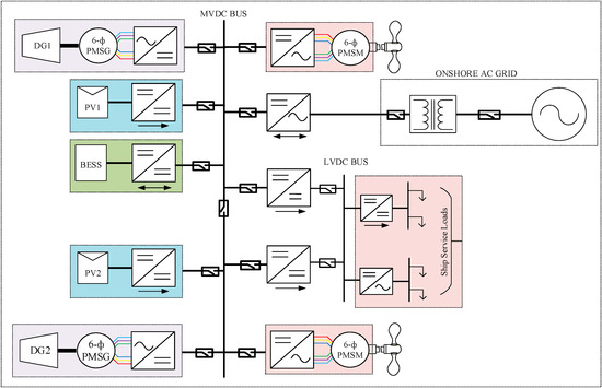
Figure 1.
Single line diagram of hybrid MVDC power system architecture considered for a cruise ship.
Electrical generators form the major power source of the shipboard microgrid in delivering the mechanical power from the diesel engine to the MVDC distribution system via an appropriate converter. References [12,13,14,15] provide a detailed overview of the generators/alternators applicable for the MVDC distribution system with their possible merits, demerits, and applicability, in addition to the technologies under research and development. In [13], some proven technology of alternators for the onboard MVDC grid, such as wound-field salient pole low-speed alternators, wound-field laminated round rotor alternators, turbo-alternators, and permanent magnet synchronous generator (PMSG), are mentioned. In addition to that, it also highlights the importance of PMSG machines as a suitable generator to supply DC systems through rectifiers, but it does not provide detailed results and discussion on the application of PMSG as a potential alternator for onboard MVDC grid. Furthermore, [15] also focuses on the employment of PMSG as an onboard generator and provides simulation results to verify the suitability of PMSG as the potential alternator. PMSG, despite being a strong candidate for a generator of the onboard power system, another very specific issue to be addressed is to guarantee continuity of motoring and generating operations for use in electric ships. In this context, a simple three-phase PMSG may not be the potential solution. Hence, [1,13] suggest the adoption of multiphase technology for their inherent fault tolerance features and reduced power rating per phase in an electric propulsion system. In the same context, [16,17] purpose the use of multiphase multipulse generation for the MVDC system with cascading of the rectifier unit for realizing a higher number of phases. However, [18] states that output performance advantages, which could be gained by increasing the number of phases above six, are not significant. Therefore, in this paper, we consider six-phase PMSM as a suitable candidate for both generation and propulsion purposes.
An appropriate control strategy is required for the proper coordination between the load and generator within the system. Several control strategies have been reviewed in [19,20] for land-based dc microgrid, which are more or less applicable for the onboard DC distribution system. Master and slave control, DC bus signaling, and hierarchical droop control are some of the well-known control strategies for a land-based microgrid. Hierarchical control has become a standardized control structure in DC microgrid because it can optimize and control the dynamic and stable process in multiple time scales and multiple dimensions, ensuring system stability and economy [21]. However, the hierarchical control approach is least discussed regarding the future shipboard DC distribution/microgrid control. Therefore, in this paper, the hierarchical control approach is used as the mainframe of the control. Another very specific issue regarding shipboard MVDC distribution is the design and implementation of an efficient power management system (PMS) for optimal scheduling of onboard generators and electric loads. A well-designed PMS is always able to meet the load demand in an optimal way, thus enhancing the system reliability and safety. In this context, extensive research work was carried out in recent years, such as [22] that proposes rule-based energy management system (EMS) with the objective of equivalent fuel consumption minimization for DP vessels with AC system architecture. Similarly, model predictive control (MPC) based EMS is extensively discussed in the literature [23,24,25]. In [23], the objective is to optimize the power fluctuation in electric propulsion through the combined use of batteries and capacitors. More improved adaptive MPC is proposed in [24] by integrating the prediction model with a disturbance model with the same objective as in [23]. In [25], the objective is to guarantee the high-power ramp rate of pulse power load based on state of charge (SOC) of the energy storage device for warship application. Even though these PMS strategies are robust and efficient in achieving their objectives, such as fuel saving, mitigating load power fluctuation, and enhancing battery life, the reliance on the system model and selection of prediction horizon makes them complex in their application [22]. Furthermore, references [26,27,28] use load prediction strategy to determine the optimal power split between active generators and energy storage devices, with an objective of minimal fuel consumption. However, this paper proposes a simple yet practical, deterministic rule-based PMS strategy based on the loading scenario of a cruise ship and SOC states of battery energy storage system (BESS) for a proposed shipboard MVDC distribution system.
To summarize, this paper proposes a variable speed-operated diesel engine as a prime mover; six-phase PMSM as a suitable machine for the generator, as well as propeller motor; PV system; and BESS integration to the MVDC network of a shipboard distribution system for more electric operation. Furthermore, hierarchical voltage mode droop control and rule-based PMS is proposed for a hybrid shipboard MVDC distribution system that adds to the intent of SFOC minimization. To show the pertinence and performance of the proposed topology, control system, and PMS, different test scenarios for the different operating modes of a cruise ship are introduced and analyzed.
2. System Topology Description and Component Model
A notational diagram of the MVDC shipboard system considered in this paper is shown in Figure 1. To validate the proposed topology, a radial 6 kV MVDC bus is modeled in Matlab/Simulink environment. Two variable speed diesel engines (DG1 and DG2), each rated 3MW, are connected to the six-phase permanent magnet synchronous generator (PMSG) via the mechanical link. PMSG is connected to the MVDC bus via two-level twelve-pulse voltage source converter used as an active front-end rectifier. In addition, two PV arrays, each rated 200 kW and BESS rated 600 kWh, are integrated into the system. Propulsion motors, each rated 2 MW, are also modeled as a six-phase permanent magnet synchronous motor (PMSM). Ship propellers are driven by variable speed electric motor drives. The generators are responsible for supplying power to the two propulsion motors and service loads of the cruise ship. Ship service load, such as heating, ventilation and air conditioning (HVAC), and lighting loads are supplied through a low voltage DC (LVDC) bus with suitable DC-DC or DC-AC converters, depending on the nature of the loads. Finally, the MVDC bus is extended to connect to the AC electric grid via a three-phase neutral point clamped (NPC) interlinking converter and transformer for the purpose of cold ironing.
2.1. Variable Speed Diesel Engine Model
To improve the efficiency and fuel economy, the minimum load of the constant speed diesel engine should not be less than 40–60% [29] of its rated capacity. However, variable speed operation of a diesel generator allows variation on speed according to the load condition, and hence it can even operate at a light load condition with better efficiency and minimal SFOC than constant speed operation [30,31]. A simplified dynamic model of the diesel engine used in this paper consists of a speed controller, an actuator, and an engine, as shown in Figure 2.
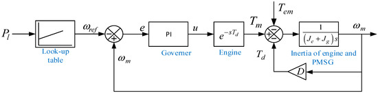
Figure 2.
A dynamic model of variable speed diesel engine.
The mechanical model of the diesel engine is represented as:
where is the angular mechanical rotational speed of an engine, is the combined inertia of the engine and PMSG, is combined viscous friction of engine and PMSG, is the mechanical torque generated by the diesel engine, and is electromagnetic torque demanded by PMSG.
To minimize fuel consumption, the optimal reference speed for the diesel engine is computed by using a look-up table where the optimal power–speed curve as given in Figure 3 is implemented.
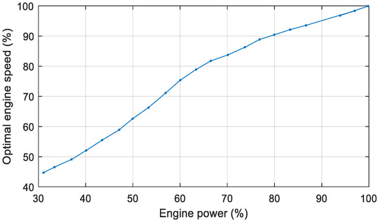
Figure 3.
Optimal speed curve reproduced for variable speed operation of the diesel engine [32].
2.2. Six-Phase PMSM Model
As noted in the introduction, to increase the power rating, smooth the electromagnetic torque pulsations, minimize harmonic content of the DC-link current, and to reduce the cost of the drive system, six-phase PMSMs are attractive in the marine propulsion system, especially in MVDC interface [33]. Several models of six-phase PMSM are reported in the literature [34,35,36]. This paper considers the six-phase PMSM with two identical three-phase stator winding sets that are balanced and star-connected, and each spatially separated from each other by 30 electrical degrees. The schematic diagram of six-phase PMSM connected to the two-level active rectifier is shown in Figure 4.
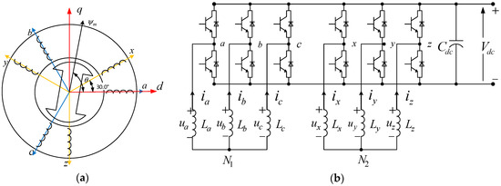
Figure 4.
Schematic diagram of six-phase PMSM with an active rectifier; (a) Winding configuration of six-phase PMSM; (b) Connection of six-phase PMSM with two-level active rectifier.
The basic stator voltage, flux linkage, and system motion equations for the PMSM in Figure 4 can be written as:
where and are the matrices of stator phase winding resistance (though not shown in the Figure 4, it cannot be neglected for a large machine) and inductance, respectively; is the maximum amplitude of permanent magnet rotor flux linkage, which is a constant; and are the vectors of stator terminal phase voltage, current, and flux linkage, respectively; is the angle between the magnetic axis of phase-a and the rotating magnetic field; are the electromagnetic torque, load torque, damping coefficient, angular velocity, and rotational inertia of the machine, respectively.
The vectors of stator terminal voltage, current, and flux linkage can be defined as:
where subscripts to represent the components of six-phases of PMSM.
Similarly, the matrices of stator phase winding resistance and inductance can be expressed as Equations (5) and (6), considering the alignment of a magnetic axis of phase-a aligned with an axis of a magnetic field.
where and are the stator leakage and magnetizing inductances.
Phase equations of six-phase PMSM in the natural coordinate frame have a current flow equation for each phase in the six-dimensional system, making the control much more complex. To simplify the control, the basic idea is to decompose the six-dimensional system into a vector space with three orthogonal subspaces, such that the one subspace contains all the electromechanical energy conversion. In this paper, traditional space vector decoupling theory [37] is used to find the basis vectors of each subspace. By using space vector decoupling theory, the harmonics of the six-phase machine variables are decoupled to three orthogonal subspaces, namely , , and ; the transformation matrix from natural coordinates to vector spaces is given as:
where T is the transformation matrix for transformation from natural coordinates to synchronous coordinates for a six-phase machine.
Now by applying the transformation given by (8) to (2), the vector space decomposition variable in a new reference frame can be expressed as:
where
and
Again by applying the transformation given by (8) to Equation (6), the stator inductance value along the subspace is calculated as (12) which can be used to update elements of matrix represented by (11).
Similarly, applying the transformation expressed in (8) to the machine model in the natural reference frame, a decoupled model of six-phase PMSG in the new reference frame can be expressed as:
Also, electromagnetic torque produced by the component of subspace is expressed as (14):
The model of the six-phase PMSM developed based on the Equations (1)–(6) can be used to simulate either a generator or propulsion motor, depending upon the direction of torque applied. The parameters used for the six-phase PMSM as generator and motor considered in this paper are provided in Table A1 of Appendix A.
2.3. PV Array Model
The escalating cost of fossil fuels and the regulatory compliance to reduce the emission of greenhouse gases has forced the shipping industry to deploy renewable energy sources, such as PV systems, as an alternative means of ecofriendly transportation [38,39]. Normally, power from the PV system depends on the solar irradiation profile and cell temperature of the PV array in an offshore installation. However, in the case of an onboard application, it also depends on other climatic factors and the nature of the voyage (longitude and latitude of navigation route) [40]. The capacity of PV installation relies on the available free deck space (roof, facade, starboard, etc.) which also depends on the type of ship. In that context, PV installation is assumed to be 20% of the total onboard generation system, as recommended in [10,40]. In this paper, with the scope of extracting the maximum power from the PV array, a flying interleaved boost converter (FIBC) is used with a variable step size incremental conductance algorithm. Since the PV system is connected to the DC-link voltage that is as high as 6 kV, the main reason behind using FIBC is to minimize the voltage stress over IGBTs and the other reason is to minimize the ripple of the input current. The design and modeling of FIBC is coherent with [41]. The circuit diagram of a PV array connected to the FIBC and single diode model of a PV cell is shown in Figure 5. Simulation and design parameters of the PV system are presented in Table A2 of Appendix A.
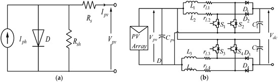
Figure 5.
Circuit diagram of PV system: (a) Equivalent model of PV cell; (b) PV array connection to FIBC.
The voltage–current characteristics of the PV cell are given by Equation (15):
where is the photocurrent, is the diode saturation current, is an electronic charge, T is temperature (K), n is P–N junction ideality factor, and and are the intrinsic series resistances of the PV cell.
The components of the FIBC can be calculated based on the Equations (16) and (17) [41]:
where is considered to be 5% of the output current that is input current ripple, is considered to be 1% of the output dc voltage that is dc-link voltage ripple, is the duty cycle, and is the switching period.
2.4. Battery Energy Storage System
In the hybrid MVDC shipboard distribution system, BESS finds its application with a wide range of scope. In this paper, the primary purpose of BESS is to improve the overall efficiency of a generator system, which allows at least one diesel engine to shut down during low load conditions. In doing so, it assists in accomplishing the intent of minimal fuel consumption and minimal pollutant emission [42]. The secondary purpose of interest is related to the idea of load leveling, which allows the diesel engines to work at constant power either by charging or discharging the BESS, ignoring the fluctuation in propulsion load demand. In doing so, BESS not only helps in improvisation of the fuel economy but also in providing additional redundancy to the shipboard power system during large transients in ship electrical load. Taking into consideration of the size of the PV system installed, potential propulsion load profile, and potential system contingencies, the sizing of BESS is considered to be 10% of total onboard generation capacity, according to reference [43]. A Li-ion model battery is used for its advantage of high power density. For interfacing BESS to the MVDC grid, an interleaved bidirectional converter (IBC) is used, as shown in Figure 6. The design and modeling of the IBC is coherent with [44]. The design and simulation parameters of the BESS system are presented in Table A3 of Appendix A.
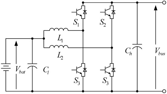
Figure 6.
BESS connection to IBC.
The components of the IBC can be computed, based on Equations (18) and (19), as given by [44]:
where is a critical value of inductance and the inductance value is taken as less than .
2.5. Dc-Link Model
The power connection between generators, energy storage devices, and loads is done through the common DC-link, which is none other than a capacitor. MVDC bus can be modeled, based on Equation (20):
where are DC-link capacitance, DC bus voltage, output DC current, and load current, respectively. The value of DC-link capacitance is determined by the ratio of energy stored in the capacitor bank and nominal power needed to be handled by an AC-DC converter connected to diesel engines, as given by the Equation (21):
In this paper, the fraction of highest cycle is taken as 0.5, nominal power MW and the DC-link voltage kV, so the capacitor value is computed by (22):
2.6. Propulsion Load Model
The mechanical load power and propeller load torque for the motion of the ship can be expressed in terms of torque and rotational speed of the propeller as (23):
where is the propeller torque and is the rotational speed of the propeller.
The PMSM is directly connected to the propeller shaft, therefore is also the rotational speed of the PMSM.
3. Hierarchical Control for MVDC Shipboard Microgrid
The hierarchical control proposed in this paper for the shipboard MVDC distribution system consists of two layers. The first layer controls the local voltages and currents, while the second layer maintains the dc voltage level and ensures proportional power sharing among the generators. The control scheme for voltage mode droop controlled system for considered shipboard power system is shown in Figure 7, Figure 8 and Figure 9.
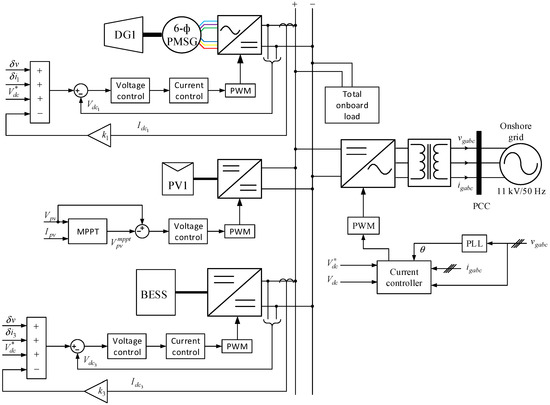
Figure 7.
Primary control layer for the proposed hierarchical control of the shipboard MVDC distribution system.
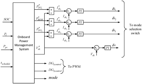
Figure 8.
Secondary control layer for the proposed hierarchical control of the shipboard MVDC distribution system.
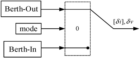
Figure 9.
Mode selection switch.
While in berth-out mode, the DC bus of an onboard MVDC distribution system is disconnected from the onshore grid, thus making it a mobile islanded DC microgrid. In this mode, the mode selection switch, as shown in Figure 9, passes the unity value such that both the primary and secondary control comes in action at the same time. The control over the DC-link from the interlinking bidirectional converter is released and onboard converters come into action to take control over the DC-link while operating in droop controlled mode. Along with that, the mode controller also signals for starting the DGs as soon as the ship enters in this mode. The total load on the system during this mode will be the sum of propulsion and ship service load.
While in a berth-in mode, the onboard MVDC distribution system is connected to an onshore ac grid via an interlinking converter, forming a grid-connected hybrid AC/DC microgrid. Therefore, in this mode, the control over the DC-link voltage is transferred to the interlinking converter by onboard PMS. Furthermore, the mode selection switch sends the zero value for the primary and secondary controller output, i.e., and , at the same time the diesel generator connected converters are turned off. Besides, in this mode, BESS can be charged at constant power for dedicated use during berth-out mode. Thus, during berth-in mode, the total load on the system will be ship service load and BESS as charging load. In this mode, the onshore grid will supply all deficit amounts of load power, which cannot be maintained by the PV system.
3.1. Primary Control
In this paper, multiple generators are considered; each generator has its own local current and voltage regulator. Since, the PV system and BESS have a simple primary control structure; their control is not described further in this paper. Furthermore, grid-connected converter control is also not presented, as it can be found in many other researches [45,46]. However, the primary control of the six-phase propulsion system is complex and discussed in detail.
3.1.1. Primary Current Control
The overall control structure of the six-phase PMSG has three control loops: speed control loop, DC-link voltage control loop, and current control loop, as shown in Figure 10. The current control loops form the primary current control structure. As expressed in (13), the model of six-phase PMSG in subspace is composed of fundamentals and harmonics. Since the fundamental component interacts with the rotor flux linkage in the air gap of the PMSM, it is responsible for generating electromagnetic torque [47]. Therefore, control of the component along subspace will control the electromagnetic power flow in PMSM. However, for the non-salient pole six-phase PMSG considered, ; electromagnetic torque will be linear only with q-axis component as expressed below:
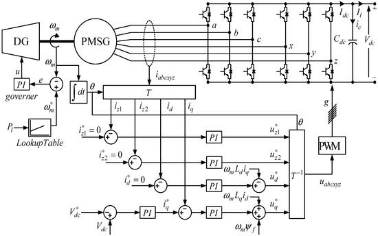
Figure 10.
Voltage and current control loop for the engine-connected six-phase PMSG.
Therefore, the d-axis component along the subspace is set to zero . Furthermore, components along the subspace are composed of harmonics. Components along the subspace would cause energy loss [48], which ultimately reduces the efficiency of PMSM, so these components are also controlled with zero referencing to improve the energy conversion efficiency.
The overall control equations for the current control loop resulting in the required terminal voltage are expressed as:
where , and are the proportional and integral gain of outer voltage loop control and the inner current loop control, respectively.
The control strategy of the PMSM as a motor is the same as that of the PMSM as a generator, except the outer voltage control loop is replaced by a speed control loop, as shown in Figure 11. The outer speed control loop is designed to run the propeller motor at the desired angular speed so that the ship travels at a specified speed . The ship operator determines the specified speed of the ship. Transformation of specified linear ship speed to angular speed depends upon the propeller blade pitch angle and rotor diameter, if the water is assumed as an inelastic medium. For simulation, these dependencies are simplified by a constant factor in this paper. It should be noted that the reference q-axis current would be positive for PMSM in motoring mode.
where and are the proportional and integral gain of the outer speed control loop of PMSM as propeller motor.
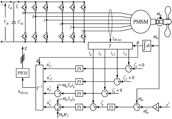
Figure 11.
Speed and current control loop for PMSM as a motor connected to the propeller.
3.1.2. Primary Voltage Control
Since voltage mode droop-based power-sharing strategy is used in this paper, a DC voltage reference for the local voltage controllers is generated based on the V–I droop characteristics of the generator. The reference voltage value can be computed as:
where , , , and are the filtered output current, droop coefficient, measured output voltage, and reference output dc-link voltage of the converter.
For the topology considered in our case, PV is of non dispatchable nature and does not take part in the DC-link voltage balancing, thus (28) holds valid for the only PMSG connected converter and BESS system.
3.2. Secondary Control
Secondary control is responsible for maintaining the DC-link voltage level, irrespective of the change in load condition. A secondary voltage controller term known as voltage shifting term [49] is added to (28) to restore the drop in DC bus voltage introduced due to the droop controller and to enhance the power-sharing accuracy, as given by (29)
where and are a nominal and measured value of MVDC bus voltage.
Besides the voltage level balancing, another important function in an onboard DC grid is to control the power/current flow from the different onboard generators. For this propose in this paper, a secondary current controller is proposed for each generator, which adjusts the power flow references as determined by PMS accordingly. Thus, after adding a secondary power flow controller, equation (30) can be expressed as:
where and are the reference and measured value of the current of generator of the onboard MVDC distribution system.
3.3. PMS
Rule-based PMS strategy is proposed to compute the load sharing for each generator based on its capacity. The developed strategy relies on the predefined states of loading scenario for different operating modes and SOC condition of BESS. Whenever possible, PMS is designed such that it performs the scheduling of dispatchable generators (DG1 and DG2) at their minimal SFOC zone, i.e., at their optimal operating point.
For a mobile islanded onboard power distribution system, the internal power balance at each time step is given as:
The developed pseudocode of PMS, as shown Table 1, is bounded by constraints (33)–(35), such that the power balance condition (36) is always preserved. The PMS system reads the of BESS, load power , and output PV power as input, and produces control (turn on/off and charging/discharging decisions for DGs and BESS respectively) as well as reference power signals for DGs and BESS as output. Whenever possible, the BESS system is charged or discharged equivalently with the amount of power production from PV system so as to avoid the power disturbance that may arise due to the stochastic nature of power from the PV system. PMS is designed such that DG1 is operated at its optimal power (85% of its nominal power) for most of the time so as to have minimal SFOC consumption. Since the load of the ship varies depending largely on its cruising speed, as the load demand exceeds the optimal power of DG1, i.e., (), DG2 comes in action. Such design leads to the operation of DG2 in variable speed mode most of the time, which supplies the excess load after the optimal operating point of DG1. However, when the load on the ship is quite high, DG2 is also operated at its optimal power, i.e., (), and BESS will operate in peak shaving mode to supply excess load. BESS as shown in Table 1, when , mostly works in discharge mode and may remain in standby mode; when , works either in charging or discharging mode; and when , it works in charging mode. BESS, while operating in these different modes, will perform peak shaving and load leveling actions, which will be demonstrated in simulation results in a later section.

Table 1.
Rule-based PMS pseudocode in tabular form.
4. Simulation Results
4.1. Loading Scenario Under Considerations
For a high fidelity detailed model of shipboard power system considered in this paper, it is unfeasible to simulate the complete load profile of a voyage due to the high computational burden. Therefore, different load levels corresponding to different modes of ship operation are considered in the scale of seconds, as shown in Figure 12. Herein, load levels corresponding to four modes of operation are defined relative to the ship speed, namely: maneuvering out of the port (0–18 s); cruising at open sea (18–82 s), which is also divided into two modes (medium speed cruising at 15 knots and full speed cruising at 25 knots); and maneuvering into the port (98–115 s). To validate the proposed PMS and control strategy, these load levels are joined together such that the transition from one mode to another mode can be simulated continuously and dynamics of the system can be observed under such transitions.
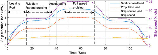
Figure 12.
Loading levels considered for different operating modes of a cruise ship.
4.2. Verification of Six-Phase PMSM Operations
For the verification of six-phase PMSM operation, a single generator–single propeller (SGSP) six-phase PMSM system, as shown in Figure 13 is simulated. For the SGSP system, the propeller load is half of the total propulsion load, at each time step of the simulation.
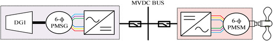
Figure 13.
Single generator–single propeller (SGSP) six-phase PMSM system.
The ship speed profile, see Figure 14a, representing the different operating modes is given as the input in Figure 11 for the SGSP system simulation study. The propeller power requirement to thrust the ship in forward motion for given speed conditions is given in Figure 14b, which is negative and equal to the power supplied by a diesel engine, as shown in Figure 14d. Below 10 s, load on the diesel engine is less than 30% of its rated power, so it runs at specified minimal optimal speed so as to minimize SFOC. After 10 s, the load is greater than 30% and ramping up, so the diesel engine runs at varying optimal speed until the load is almost constant at the medium speed cruising section, where it runs nearly in constant optimal speed. This tendency of variable optimal speed operation and constant optimal speed operation of the diesel engine depending on the loading condition is clearly demonstrated in Figure 14c. The dc-link voltage for the range of loading condition is stable, as shown by Figure 14e. The negative q-axis current, as shown in Figure 14f, shows the range of current to be delivered by the PMSG for the different loading conditions considered.
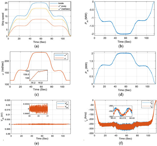
Figure 14.
SGSP–PMSM system simulation results: (a) speed of ship PMSM-connected ship propeller; (b) mechanical power from PMSM to drive the propeller; (c) variable operating speed of the diesel engine for the given load; (d) mechanical power supplied by the diesel engine to PMSG; (e) dc-link voltage waveform; (f) q-axis current response of PMSG.
Figure 15 shows the current waveform of six-phase PMSG for delivering the required power to the propeller under different loading conditions. The magnified view of the current waveform in Figure 15b–d shows different operating frequencies at different loading conditions, which is because of the variable speed operation of a diesel engine.
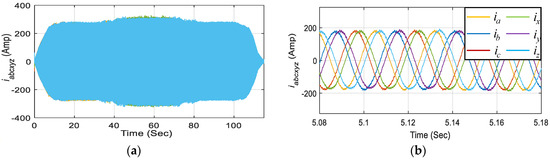
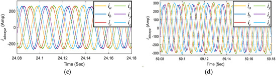
Figure 15.
Stator current waveforms of six-phase PMSG operating in variable speed mode: (a) Six-phase current at stator terminal supplied by PMSG; (b) magnification of (a) at an optimal speed rad/s; (c) magnification of (a) at an optimal speed rad/s; (d) magnification of (a) at an optimal speed rad/s.
4.3. Full System Simulation Under Berth-Out and Berth-In Mode
4.3.1. Berth-Out Mode
In berth-out mode, simulation is carried out for loading conditions of Figure 12, with three different cases, namely, SOC high, SOC within limit, and SOC low, based on the PMS defined in Table 1. Since, the rating of PV array installed for onboard application is much lower compared to the rating of diesel engine sets, PV array when simulated for a lower value of PV output power, its effect on the system is minimal and hence, not clearly observable. Therefore, to demonstrate the effect of the PV array on the system, such that all the transition points are observable, results are presented when the output power produced from both PV arrays is maximum, i.e., 400 kW.
Figure 16a presents the power flow waveforms of the considered topology of an all-electric ship in berth-out mode while SOC of BESS is high (). When SOC is high, BESS is normally subjected to a discharge condition. Output power from the PV array is injected continuously into the system for the entire period of simulation. For the first 10.5 s, BESS remains in standby mode and the load is supplied only by DG1 operating in variable speed mode. After 10.5 s, BESS comes in action such that BESS and DG1 are operating together in droop controlled mode to supply the load. At 14 s, load level is very high, so DG2 also comes online such that BESS, DG1, and DG2 all are operating in droop controlled mode and generating the power as defined by PMS. System transients when DG2 comes online are due to the sluggish nature of the diesel engine as compared to other system generators. Until 101 s, DG1 operates at its optimal power (85% of its rated capacity), DG2 operates in variable speed mode supplying variable amount of load, and BESS is discharged at the rate defined by PMS. After 101 s, load is ramping down so DG2 goes offline and active generators are only DG1 and BESS. After 114 s, BESS goes in standby mode and only DG1 is supplying the load.
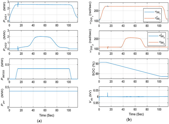
Figure 16.
Simulation results of berth-out mode while BESS SOC is high: (a) power flow from the onboard generators; (b) operating speed of DG sets, SOC of BESS, and DC-link voltage waveform.
In Figure 17, simulation results of berth-out mode while SOC of BESS is within the specified range () are presented. During the beginning, load level considered is low, so only DG1 is turned on, DG2 is kept offline, and BESS is subjected to charge equivalently to the power available from the PV. As the load level is ramping up, at around 10.5 s, optimal operating power level of DG1 is already reached and it is subjected to optimal power operation. After 10.5 s, the charging power of BESS is decreased until 13 s, when it transits from charging to discharging mode so as to cope with the ramping load. After 14 s, the load level becomes significantly high, so DG2 needs to come online to match the load demand. After 43 s, load ramping reaches a significant amount, such that DG2 is also operated at its optimal power. At the same time, the total power produced from optimal operation of both the DG sets and the PV array exceeds the load demand and hence, BESS is charged with the excess amount of power produced. The power flow explanations after 60 s are the same as described above since the loading levels considered are symmetrical.
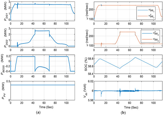
Figure 17.
Simulation results of berth-out mode while BESS SOC is within range: (a) power flow from the onboard generators; (b) operating speed of DG sets, SOC of BESS, and dc-link voltage waveform.
In Figure 18, simulation results of berth-out mode while SOC of BESS is low () are presented. Since the SOC of BESS is low, it is normally subjected to charging. At the beginning, load level is low, so only DG1 is kept on and BESS is subjected to charge with the power equivalent to generated PV power. At 14 s, load demand reaches a significant value such that DG1 is operated at optimal power and rest of the load is handled by DG2 operating in variable speed mode. At 43 s, load level reaches the value such that two DG sets are operated in optimal mode and charging level of BESS is reduced to match the load demand. After 70 s, load level reaches the value that can be handled only by two DGs, so BESS is again charged with the equivalent amount of power available from the PV array.
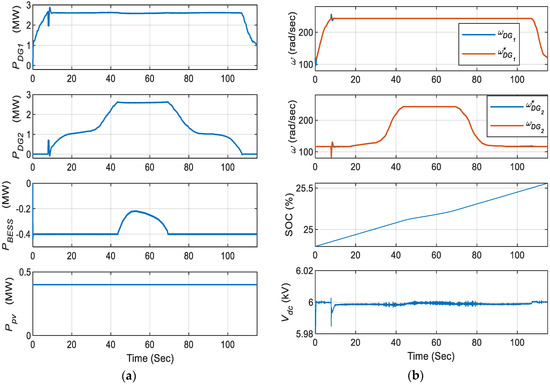
Figure 18.
Simulation results of berth-in mode while BESS SOC is low: (a) power flow from the onboard generators; (b) operating speed of DG sets, SOC of BESS, and DC-link voltage waveform.
Simulation results in Figure 16, Figure 17 and Figure 18b show the variable operating speed of the diesel engine sets, SOC states of BESS, and DC-link voltage of the system under different SOC levels. Operating speed of the diesel engines and DC-link voltage waveform are stable under different operating conditions, ensuring the stability of the system.
4.3.2. Berth-In Mode
While in a berth-in mode, since diesel engine sets are offline, only the PV array and BESS will be the onboard power generators and the system will resemble a grid-connected PV system. For the simulation in a berth-in mode, both PV arrays are subjected to the same irradiance profile and BESS is subjected to charge at constant power, for dedicated use during berth-out mode.
The simulation results in Figure 19 show the current and voltage waveform of the system during berth-in mode. The loading level imposed on the system during berth-in mode is shown in Figure 20. For brevity, only the waveforms of one PV array are presented, as both PV arrays are equal in size, and subjected to same irradiance profile, they will have the same current and voltage dynamics. As depicted in Figure 19a, a variable irradiance profile lasting up to 6 s is subjected to the PV array; PV voltage is tracked around the maximum power point voltage of 1530 volts staying within the limit of voltage variation. For the considered irradiance profile the PV current is changing according to the change in insolation so as to produce the respective amount of power. Similarly in Figure 19b, as BESS is subjected to constant charging, its voltage is rising from the voltage level of the discharged state corresponding to 25% SOC. Negative constant current and increasing SOC depicts constant rate charging of BESS. In addition, Figure 19c shows the stable current and voltage waveform of the onshore grid while maintaining the power flow in the system. The grid is supplying the current to the onboard load, based on the power production from the onboard PV array.
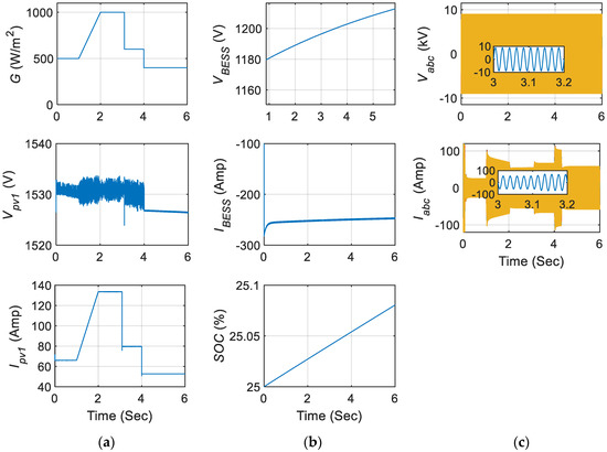
Figure 19.
System characteristics during berth-in mode: (a) insolation, PV output voltage, and current waveform; (b) BESS voltage, current, and SOC waveform; (c) grid side voltage and current waveform at the point of common coupling.
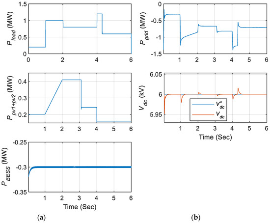
Figure 20.
Power flow and DC-link voltage waveform during berth-in mode: (a) Loading level during berth-in mode, combined output power from PV arrays and charging power of BESS; (b) Deficit power supplied by onshore grid and DC-link voltage waveform.
The simulation results in Figure 20 show the power flow waveforms between the onshore grid and onboard system, and the DC-link voltage waveform during berth-in mode. Since, power output from PV array alone is insufficient to supply the load added to the charging power of BESS, deficit amount of power is supplied by the onshore grid as shown in Figure 20b. Furthermore, dc-link voltage is stable during the major load changes and variation in output power of PV system, ensuring the stable operation of onboard power system.
5. Conclusions
This paper presented the modeling and simulation of the MVDC distribution system for an all-electric ship. Normally, an all-electric ship with the onboard MVDC bus is composed of different generators, power electronics components, and control system structure. All these components and the control structure were modeled and simulated in the Matlab/Simulink environment. It was found that the developed model had satisfactory performance for the operating scenarios that were considered. The mathematical model and control structure of the novel onboard six-phase PMSM propulsion system was introduced and discussed in detail. Simulation results of SGSP system verified the reliability and adaptability of the novel onboard six-phase propulsion system proposed. Furthermore, the proposed topology of the shipboard MVDC distribution system combined with hierarchical control structure and rule-based PMS was tested under respective load levels of different operating conditions during berth-out and berth-in mode. The performance of proposed topology was stable in terms of power delivery, dynamics of DC-link voltage, and frequency of the onboard generator throughout the simulation for both berth-out and berth-in mode. The proposed system could be extended for future research with the scope of seamless interconnection during changeovers of berth-out to a berth-in mode, which is not covered in this paper.
Author Contributions
A.L. and L.Z. conceived and designed the topology; A.L. performed modeling, simulation, control development, and edited the draft with guidance from G.Y. and L.Z.; L.Z. and M.L. checked the language, style of manuscript, and made a contribution to the revision of manuscript. All authors have read and agreed to the published version of the manuscript.
Funding
This research was supported by the Shanghai Natural Science Foundation (SNSF) under grant 18ZR1418400.
Acknowledgments
We would like to thank Tron Hansen Syverud for providing copyright permission on reproducing a graph from his Master’s thesis as mentioned in reference [32]. In addition, we are particularly grateful for the continuous support and suggestion given by Professor. Tie Li from State Key Laboratory of Ocean Engineering, Shanghai Jiao Tong University while carrying out this research work.
Conflicts of Interest
The authors declare no conflict of interest.
Appendix A. Design Parameters of System Components
Table A1.
Parameters of PMSM as a generator and motor.
Table A1.
Parameters of PMSM as a generator and motor.
| Parameter | Generator | Motor | Unit |
|---|---|---|---|
| Rated Power | 3 | 2 | MW |
| Number of pole pairs, | 2 | 6 | - |
| Magnetizing inductance, | 3.3315 | 3.331 | mH |
| Leakage inductance, | 1.5 | 1.1 | mH |
| Rotor flux linkage amplitude, | 4.759 | 4.759 | Wb |
| Stator phase winding resistance, | 0.02425 | 0.002425 | ohm |
| Switching frequency of ac–dc converter, | 3 | 3 | kHz |
| Time delay, | 16.6 | 16.6 | ms |
| Linear to angular speed conversion factor, | - | 1.6427 | - |
Table A2.
Design parameters of FIBC.
Table A2.
Design parameters of FIBC.
| Parameter | Value | Unit |
|---|---|---|
| Rated power of PV array | 200 | kW |
| Maximum power point voltage at STC | 1530 | V |
| FIBC inductance value, | 3 | mH |
| Dc-link capacitance value, | 95,500 | µF |
| PV side capacitance value, | 5000 | µF |
| ESR of the inductor, | 0.005 | ohm |
| ESR of the capacitor, | 0.002 | ohm |
| Switching frequency if FIBC, | 5 | kHz |
| DC bus voltage, | 6 | kV |
Table A3.
Design parameters of BESS.
Table A3.
Design parameters of BESS.
| Parameter | Value | Unit |
|---|---|---|
| Rated power of BESS | 600 | kWh |
| Nominal rated voltage of BESS, | 1200 | V |
| IBC inductance value, | 4.5 | mH |
| Dc-link capacitance value, | 95,500 | µF |
| Switching frequency if IBC, | 10 | kHz |
| DC bus voltage, | 6 | kV |
References
- Yang, T.; Cox, T.; Degano, M.; Bozhko, S.; Gerada, C. History and Recent advancements of Electric Propulsion and Integrated Electrical Power Systems for Commercial & Naval Vessels. In Proceedings of the International Naval & Maritime Exhibition and Congress for Latin America, ExpoNAVAL 2016, Vina Del Mar, Chile, 29 November–2 December 2016. [Google Scholar]
- Hansen, J.F.; Wendt, F. History and State of the Art in Commercial Electric Ship Propulsion, Integrated Power Systems, and Future Trends. Proc. IEEE 2015, 103, 2229–2242. [Google Scholar] [CrossRef]
- Sulligoi, G.; Vicenzutti, A.; Menis, R. All-Electric Ship Design: From Electrical Propulsion to Integrated Electrical and Electronic Power Systems. IEEE Trans. Transp. Electrif. 2016, 2, 507–521. [Google Scholar] [CrossRef]
- Bosich, D.; Vicenzutti, A.; Pelaschiar, R.; Mensi, R.; Sulligoi, G. Toward the future: The MVDC large ship research program. In Proceedings of the AEIT International Annual Conference, Naples, Italy, 14–16 October 2015. [Google Scholar]
- IEEE Recommended Practice for 1 kV to 35 kV Medium-Voltage DC Power Systems on Ships; in IEEE Standard 1709–2010. Available online: https://ieeexplore.ieee.org/document/5623440 (accessed on 20 March 2020).
- Doerry, N.; Amy, J.V. Design Considerations for a Reference MVDC Power System. In Proceedings of the SNAME Maritime Convention, Bellevue, WA, USA, 1–5 November 2016; Available online: https://www.onepetro.org/conference-paper/SNAME-SMC-2016-022 (accessed on 20 March 2020).
- Kim, K.; Park, K.; Roh, G.; Chun, K. DC-grid system for ships: A study of benefits and technical considerations. J. Int. Marit. Saf. Environ. Aff. Shipp. 2018, 2, 1–12. [Google Scholar] [CrossRef]
- Symington, W.P.; Belle, A.; Nguyen, H.D.; Binns, J.R. Emerging technologies in marine electric propulsions. J. Eng. Maritime Environ. 2014, 203, 187–198. [Google Scholar] [CrossRef]
- Ghenai, C.; Bettayeb, M.; Brdjanin, B.; Hamid, A.K. Hybrid solar PV/PEM fuel Cell/Diesel Generator power system for cruise ship: A case study in Stockholm, Sweden. Case Stud. Therm. Eng. 2019, 14, 65–76. [Google Scholar] [CrossRef]
- Satpathi, K.; Balijepalli, M.; Ukil, A. Modeling and Real-Time Scheduling of DC Platform Supply Vessel for Fuel Efficient Operation. IEEE Trans. Transp. Electrif. 2017, 3, 762–778. [Google Scholar] [CrossRef]
- Lee, K.J.; Shin, D.S.; Lee, J.P.; Yoo, D.W.; Choi, H.K.; Kim, H.J. Hybrid photovoltaic/diesel green ship operating in standalone and grid-connected mode–Experimental investigation. Energy 2013, 49, 475–483. [Google Scholar] [CrossRef]
- Javaid, U.; Freijedo, F.D.; Dujic, D.; Merwe, W.V.D. MVDC supply technologies for marine electrical distribution systems. CPSS Trans. Power Electron. Appl. 2018, 3, 65–76. [Google Scholar] [CrossRef]
- Tessarolo, A.; Castellan, S.; Menis, R.; Sulligoi, G. Electric generation technologies for all-electric ships with Medium-Voltage DC power distribution systems. In Proceedings of the IEEE Electric Ship Technologies Symposium, Arlington, VA, USA, 22–24 April 2013. [Google Scholar]
- McCoy, T.J. Trends in ship electric propulsion. In Proceedings of the IEEE Power Engineering Society Meeting, Chicago, IL, USA, 21–25 July 2002. [Google Scholar]
- Ourora, A.; Jackson, J.R.; Beno, J.H.; Thompson, R.C.; Schroeder, E. Modeling and Simulation of electric ship’s power system components and their interaction. In Proceedings of the Summer Computer Simulation Conference, San Diego, CA, USA, 15–18 July 2007. [Google Scholar]
- Sulligoi, G.; Tessarolo, A.; Benucci, V.; Baret, M.; Rebora, A.; Taffone, A. Modeling, simulation and experimental validation of generation system for Medium-Voltage DC Integrated Power Systems. In Proceedings of the IEEE Electric Ship Technologies Symposium, Baltimore, MD, USA, 20–22 April 2009. [Google Scholar]
- Sulligoi, G.; Tessarolo, A.; Benucci, V.; Trapani, A.M.; Baret, M.; Luise, F. Shipboard Power Generation: Design and development of a medium-voltage dc generation system. IEEE Ind. Appl. Mag. 2013, 19, 47–55. [Google Scholar] [CrossRef]
- Tessarolo, A. Experimental performance assessment of multiphase alternators supplying multiple AC/DC converters. J. Energy Power Eng. 2010, 4, 43–50. [Google Scholar]
- Kumar, J.; Agarwal, A.; Agarwal, V. A review on overall control of DC microgrids. J. Energy Storage 2019, 21, 123–138. [Google Scholar] [CrossRef]
- Gao, F.; Kan, R.; Cao, J.; Yang, T. Primary and secondary control in DC microgrid: A review. J. Mod. Power Syst. Clean Energy 2019, 7, 227–242. [Google Scholar] [CrossRef]
- Zhoxia, X.; Tianli, Z.; Huaimin, L.; Guerrero, J.M. Coordinated Control of a Hybrid-Electric-Ferry. IEEE Trans. Transp. Electrif. 2019, 5, 828–839. [Google Scholar] [CrossRef]
- Dinh, T.Q.; Bui, T.M.N.; Marco, J.; Watts, C.; Yoon, J.I. Optimal Energy Management for Hybrid Electric Dynamic Positioning Vessels. IFPAC PapersOnLine 2018, 51, 98–103. [Google Scholar] [CrossRef]
- Hou, J.; Sun, J.; Hofmann, H.F. Mitigating Power Flucations in Electric Ship Propulsion with Hybrid Energy Storage System: Design and Analysis. IEEE J. Ocean Eng. 2018, 43, 93–107. [Google Scholar] [CrossRef]
- Papalambrou, G.; Samokhin, S.; Topaloglou, S.; Planakis, N.; Kyrtatos, N.; Zenger, K. Model Predictive Control for Hybrid Diesel-Electric Marine Propulsion. IFAC PapersOnLine 2017, 50, 11064–11069. [Google Scholar] [CrossRef]
- Vu, T.V.; Gonsoulin, D.; Perkins, D.; Diaz, F.; Vahedi, H.; Edrington, C.S. Predictive Energy Management for MVDC All-Electric Ships. In Proceedings of the IEEE Electric Ship Technologies Symposium (ESTS), Arlington, VA, USA, 15–17 August 2017. [Google Scholar]
- Vu, T.L.; Ayu, A.A.; Dhupia, J.S.; Kennedy, L.; Adnanes, A.K. Power Management for Electric Tugboats Through Operating Load Estimation. IEEE Trans. Control Syst. Technol. 2015, 23, 2375–2382. [Google Scholar] [CrossRef]
- Yuan, L.C.W.; Tjahjowidodo, T.; Lee, G.S.G.; Chan, R.; Adnanes, A.K. Equivalent Consumption Minimization Strategy for hybrid all-electric tugboats to optimize fuel savings. In Proceedings of the American Control Conference, Boston, MA, USA, 6–8 July 2016. [Google Scholar]
- Kenellos, F.D.; Anavari-Moghaddam, A.; Guerrero, J.M. Smart Shipboard Power System Operation and Management. Inventions 2016, 1, 22. [Google Scholar] [CrossRef]
- Farhan, B.S.; Wang, S.; Salih, H.W. Control of Variable Speed Diesel Generator using FOC in Hybrid Systems. Int. J. Control Autom. 2016, 9, 111–122. [Google Scholar] [CrossRef]
- Lee, J.H.; Lee, S.H.; Sul, S.K. Variable-Speed Engine Generator with Supercapacitor: Isolated Power Generation System and Fuel Efficiency. IEEE Trans. Ind. Appl. 2009, 45, 2130–2135. [Google Scholar]
- Choi, I.; Jeung, Y.C.; Lee, D.C. Variable Speed Control of Diesel Engine-Generator using Sliding Mode Control. In Proceedings of the IEEE Transportation Electrification Conference and Expo, Harbin, China, 2–5 August 2017. [Google Scholar]
- Syverud, T.H. Modeling and Control of a DC-grid Hybrid Power System with Battery and Variable Speed Diesel Generators. Master’s Thesis, Norwegian University of Science and Technology, Trondheim, Norway, June 2016. [Google Scholar]
- Bojoi, R.; Tenconi, A.; Profumo, F.; Griva, G.; Martinello, D. Complete Analysis and Comparative Study of Digital Modulation Technique for Dual Three-Phase AC motor Drives. In Proceedings of the IEEE Annual Power Electronics Specialists Conference, Queensland, Australia, 24–27 June 2002. [Google Scholar]
- Zhang, K.; Kojabadi, H.M.; Wang, P.Z.; Chang, L. Modeling of a Converter-Connected Six-Phase Permanent Magnet Synchronous Generator. In Proceedings of the International Conference on Power Electronics and Drive Systems, Kuala Lampur, Malaysia, 28 November–1 December 2005. [Google Scholar]
- Duran, M.J.; Kouro, S.; Wu, B.; Levi, E.; Barrero, F.; Alepuz, S. Six-phase PMSG wind energy conversion system based on medium-voltage multilevel converter. In Proceedings of the European Conference on Power Electronics and Applications, Birmingham, UK, 30 August–1 September 2011. [Google Scholar]
- Tomer, A.S.; Dubey, S.P. Performance Analysis of Two Inverter Fed Six Phase PMSM Drive. In Proceedings of the Nirma University International Conference on Engineering, Ahmedabad, India, 28–30 November 2013. [Google Scholar]
- Hoem, Q.M.M. Control of Six-Phase Machines. Master’s Thesis, Norwegian University of Science and Technology, Trondheim, Norway, June 2009. [Google Scholar]
- Spagnolo, G.S.; Papalilo, D.; Martocchia, A. Eco friendly electric propulsion boat. In Proceedings of the International Conference on Environment and Electrical Engineering, Rome, Italy, 8–11 May 2011. [Google Scholar]
- Katagi, T.; Fugii, Y.; Nishikawa, E.; Hashimoto, T.; Ishida, K. Photovoltaic Generating System on Ships to Reduce Fossil Fuel Dependence. Available online: http://archive.jime.jp/e/publication/bulletin/english/pdf/mv24n021996p70.pdf (accessed on 20 March 2020).
- Kobougies, I.; Tatakis, E.; Prousalidis, J. PV system Installed in Marine Vessels: Technologies and Specifications. Adv. Power Electron. 2013, 2013, 831560. [Google Scholar] [CrossRef]
- Kabalo, M.; Paire, D.; Blunier, B.; Bouquain, D.; Simoes, M.C.; Miraoui, A. Experimental evaluation of four-phase floating interleaved boost converter design and control for fuel cell applications. IET Power Electron. 2012, 6, 215–226. [Google Scholar] [CrossRef]
- Zahedi, B.; Norum, L.E.; Ludvigsen, K.B. Optimized efficiency of all-electric ships by dc hybrid power systems. J. Power Sources 2014, 255, 341–354. [Google Scholar] [CrossRef]
- Boveri, A.; Silvestro, F.; Molinas, M.; Skjong, E. Optimal Sizing of Energy Storage Systems for Shipboard applications. IEEE Trans. Energy Convers. 2019, 34, 801–811. [Google Scholar] [CrossRef]
- Zhang, J. Bidirectional DC-DC Power Converter Design Optimization, Modeling and Control. Ph.D. Thesis, Virginia Polytechnic Institute and State University, Blacksburg, VA, USA, 30 January 2008. [Google Scholar]
- Anil, L.; Lidan, Z.; Yao, G.; Luqman, M. LCL Filter Based Grid-Connected Photovoltaic System with Battery Energy Storage. In Proceedings of the 14th IEEE Conference on Industrial Electronics and Applications (ICIEA), Xian, China, 19–21 June 2019. [Google Scholar]
- Liserre, M.; Blaabjerg, F.; Hansen, S. Design and Control of an LCL-Filter-Based Three-phase Active Rectifier. IEEE Trans. Ind. Appl. 2005, 2, 1281–1291. [Google Scholar] [CrossRef]
- Zhang, H.; Yao, G.; Lidan, Z.; Mei, B.; Li, D. Sliding Mode Control Based on Six-Phase PMSM Speed Control System. In Proceedings of the 43rd Annual Conference of the IEEE Industrial Electronics, Beijing, China, 29 October–1 November 2017. [Google Scholar]
- Karttunen, J.; Kallio, S.; Peltoniemi, P.; Silventoinen, P.; Pyrhonen, O. Dual Three-Phase Permanent Magnet Synchronous Machine Supplied by Two Independent Voltage Source Inverters. In Proceedings of the International Symposium on Power Electronics, Electrical Drives, Automation and Motion, Sorrento, Italy, 20–22 June 2012. [Google Scholar]
- Wang, P.; Lu, X.; Yang, X.; Wang, W.; Xu, D. An Improved Distribution Secondary Control Method for DC Microgrids with Enhanced Dynamic Current Sharing Performance. IEEE Trans. Power Electron. 2016, 31, 6658–6673. [Google Scholar] [CrossRef]


© 2020 by the authors. Licensee MDPI, Basel, Switzerland. This article is an open access article distributed under the terms and conditions of the Creative Commons Attribution (CC BY) license (http://creativecommons.org/licenses/by/4.0/).