Abstract
The China Fusion Engineering Test Reactor (CFETR) is a tokamak device to validate and demonstrate fusion engineering technology. In CFETR, the breeding blanket is a vital important component that is closely related to the performance and safety of the fusion reactor. Neutronics/thermal-hydraulics (N/TH) coupling effect is significant in the numerical analysis of the fission reactor. However, in the numerical analysis of the fusion reactor, the existing coupling code system mostly adopts the one-way coupling method. The ignorance of the two-way N/TH coupling effect would lead to inaccurate results. In this paper, the MCNP/FLUENT code system is developed based on the 3D-1D-2D hybrid coupling method. The one-way and two-way N/TH coupling calculations for two typical blanket concepts, the helium-cooled solid breeder (HCSB) blanket and the water-cooled ceramic breeder (WCCB) blanket, are carried out to study the two-way N/TH coupling effect in CFETR. The numerical results show that, compared with the results from the one-way N/TH coupling calculation, the tritium breeding ration (TBR) calculated with the two-way N/TH calculation decreases by −0.11% and increases by 4.45% for the HCSB and WCCB blankets, respectively. The maximum temperature increases by 1 °C and 29 °C for the HCSB and WCCB blankets, respectively.
1. Introduction
In order to validate the science feasibility and demonstrate the engineering technology of the magnetic-confinement fusion reactor, and achieve the transition from experimental device to demonstration reactor (DEMO), the China Fusion Engineering Test Reactor (CFETR) was proposed by the China National Integration Design Group [1]. One of the most challenging tasks is to realize tritium self-sufficiency, which mainly depends on the design of the breeding blanket. To achieve the design goal of tritium breeding, energy extraction, and radiation shielding, the blanket design is significant to the performance and the safety of the CFETR.
Blanket design involves many scientific fields. The most relevant fields include neutronics and thermal-hydraulics [2,3,4,5,6,7,8,9,10,11,12,13,14], which will directly influence the operation of the fusion reactor. In the early stage, blanket design works were performed independently without considering the coupling effects among different fields. With the advances of the blanket design, the demand for high-precision numerical analysis of the blanket is growing and the integrated approach to the blanket design is getting more attractions. Utoh [15] developed a 2D nuclear/thermal coupling analysis code DOHEAT. This code adopts DOT3.5 as the 2D SN transport module, APPLE-3 as the neutronics calculation module, and a 2D steady-state heat transfer module. It was used in various Japanese blanket conceptual designs. Spagnuolo [16] developed an integrated blanket design code system MCNP/ANSYS for neutronics, thermal-hydraulics, and the mechanics design of the blanket. The code system was applied in the water-cooled lithium lead blanket (WCLL) and the helium-cooled pebble bed blanket (HCPB) for the European DEMO project. Jiang [17] and Cui [18,19] developed multi-physics integrated optimization and design platforms based on MCNP and ANSYS for the water-cooled ceramic breeder blanket (WCCB) and the helium-cooled solid breeder blanket (HCSB) of CFETR, respectively. In their work, they focus the most attention on the individual neutronics calculation or thermal-hydraulics calculation, thus the one-way coupling method was adopted. The one-way coupling method means that each solver runs only once and the feedback effects between the neutronics and thermal-hydraulics calculations are not taken into account. In reality, there is an interaction between neutronics and thermal-hydraulics. The variation of the thermal-hydraulics parameters, including the material temperature and the coolant density, will lead to the variation of the neutronics parameters like TBR and nuclear heat deposition, which will then impact the thermal-hydraulic parameters in turn.
The two-way N/TH coupling calculation has proven to be necessary in the numerical analysis of the traditional fission reactors. However, the influences of the two-way N/TH coupling effect in the fusion blanket are still unclear. To quantify the influences of the two-way N/TH coupling effect in the fusion reactor and obtain more accurate and reliable design parameters for CFETR, the two-way N/TH coupling method should be studied.
In this paper, the coupling neutron/photon continuous-energy Monte-Carlo code MCNP and the Computational Fluid Dynamics (CFD) code FLUENT are adopted to develop the two-way N/TH coupling code system. Considering there are a number of blankets and the blanket structure is extremely complicated, a 3D-1D-2D coupling method [20] is used to reduce the difficulty in modeling. Moreover, the pseudo-material method [21] is adopted to obtain neutron cross sections at the arbitrary temperature. Based on these methods, the two-way N/TH coupling effect in two main conceptual blanket design of CFETR, HCSB, and WCCB, are studied.
This paper is organized as follows. In Section 2, the two-way N/TH coupling method and the models of the HCSB blanket and the WCCB blanket are introduced. Section 3 presents numerical analyses including sensitivity analysis of temperature and the comparison between the results of one-way and two-way N/TH coupling calculations for the HCSB blanket and the WCCB blanket. Finally, the conclusions are given in Section 4.
2. Coupling Method and Blankets Models
2.1. The Two-Way N/TH Coupling Method
Generally, the N/TH coupling code system consists of two codes, neutronics solver and thermal-hydraulics solver. Many N/TH coupling codes have been developed based on different neutronics codes and thermal-hydraulics codes [22,23,24,25]. In the International Thermonuclear Experiment Reactor (ITER) project [26], neutronics code MCNP and CFD code CFX/FLUENT are appointed as the official design tools. Therefore, MCNP and FLUENT are adopted to develop the two-way N/TH coupling code system and carry out the N/TH coupling calculation in this work.
Because of the thermal motion of the nucleus, neutron cross sections will be changed at different temperatures. However, the FENDL/MC-2.1, an ACE-format nuclear data library for the Monte-Carlo simulation of fusion reactor, only provides the cross sections at room temperature. Hence, the multi-temperature cross sections should be generated in the coupling process. Considering the generation of the cross sections at a specific temperature on-the-fly based on the Doppler-broadening theory will cost huge time, the pseudo-material method is adopted to generate the cross sections. The pseudo-material method is an interpolation method to generate cross sections at a temperature T between two temperature points, TL and TH, the low temperature and the high temperature. The cross sections at TL and TH have been generated ahead. An atomic-density fraction is computed based on linear interpolation between the square root of the low temperature and the square root of the high temperature:
Then, the cross sections at temperature T could be calculated by mixing cross sections at low temperature with a fraction of and cross sections at high temperature with a fraction of . This is realized by changing the atomic density of the material in the MCNP material card.
Considering the blanket structure is complicated and the heterogeneous effect is strong, the time spent on blanket modeling and data transmission between neutronics and thermal-hydraulics codes is long in the 3D N/TH coupling calculation. In the neutronics calculation, the 3D-1D hybrid method is proved effective and time-saving. In the thermal-hydraulics calculation, although the 3D model could provide more accurate results, it will cost huge human work on modeling and computational resources. Considering that the layers layout in HCSB and WCCB, and the coolant flows mainly in two directions, the 2D model is suitable to perform the thermal-hydraulics calculation. Therefore, instead of carrying out 3D coupling calculation directly, the 3D-1D-2D hybrid coupling method is employed to improve the calculation efficiency and feasibility of the N/TH coupling. The flow chart of this procedure is shown in Figure 1.
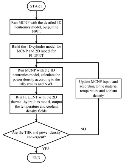
Figure 1.
Flow chart of the two-way MCNP/FLUENT coupling code system.
Firstly, to acquire accurate neutron flux distribution in different blankets, the 3D CFETR model, which contains all blankets with different dimension sizes, in-vessel components and the detailed neutron-source distribution is built to perform a neutronics calculation. The Neutron Wall Loading (NWL) obtained from the surface-tally functionality of the MCNP in 3D neutronics calculation with FENDL/MC-2.1 is utilized to normalize the actual power. The NWL is kept constant in the following iterations.
Secondly, in Figure 2, a simplified 1D cylinder model is built to obtain the radial nuclear heat power density distribution. This model is composed of two annuli, which represent for inboard blanket and outboard blanket, respectively. After finishing the 1D neutronics calculation, the radial nuclear heat power density distribution could be computed using NWL and nuclear heat distribution tallied by the F6 card of MCNP:
where p is the power density (W/m3), N is the neutron wall loading (MW/m2), A is the area of the first wall (FW) facing the plasma (m2), T is the tally result in the MCNP, which represents the nuclear heat deposition (eV) of the cell, E is the energy of the fusion neutron (MeV), and V represents the volume of material zones (m3).
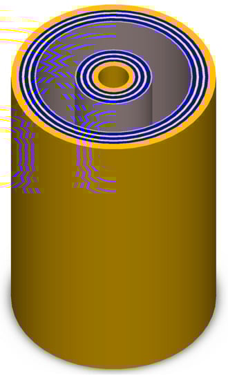
Figure 2.
1D cylinder blanket model.
Thirdly, the 2D model contains the main radial materials layers and the coolant channels are built for the CFD calculation. The radial schemes in the 2D model is the same as that of the 1D cylinder model. The 2D model is extended along the poloidal direction. To exchange required data including power density, temperature, and coolant density between MCNP and FLUENT, the zones in the thermal-hydraulics model are divided the same as the cells in the 1D neutronics model in the radial direction. Once the neutronics calculation is completed, the nuclear heat power density of each cell could be calculated according to Equation (2) and assigned as the heat source of its corresponding zone in the CFD model. After the CFD calculation is completed, the temperature distribution is obtained and is compared with that of the previous iteration. If the maximum difference is smaller than the convergence criteria, the coupling procedure is ended. Otherwise, the density information and the material in the MCNP input file will be updated according to the volume-averaged temperature of each cell and the iteration continues until convergence.
2.2. HCSB Blanket Model
The concept of the HCSB blanket [27] was proposed by the University of Science and Technology of China (USTC) for CFETR. Typical outboard blanket module structure on the equatorial is shown in Figure 3. The toroidal widths of the FW and the back plate (BP) of the blanket are 1448 mm and 1606 mm, respectively. The radial and poloidal thicknesses of the typical blanket module are 800 mm and 960 mm, respectively. A typical blanket module mainly includes tungsten armor, FW, top and bottom caps, stiffing plate (SP), cooling plate (CP), breeder zone (BZ), neutron multiplier zone (MZ), manifolds, and BP. The FW is a U-shape plate and a layer with a thickness of 2 mm of tungsten covers on it facing plasma directly. Forty-five parallel radial-toroidal-radial channels are uniformly set in the FW structure material. Helium flows through these channels and takes away the heat flux from the plasma and the neutron heat deposition. The FW, top and bottom caps, and BP construct a closed blanket box, in which 7 SPs are welded to the internal walls of the FW to enhance the mechanical property in the loss-of-coolant-accident (LOCA). Moreover, the SPs divide the blanket module into 8 equal breeding units (BUs) with a height of 106 mm in the poloidal direction. The breeder zones and the neutron multiplier zones are separately assigned in the BU in turns. The CPs are arranged between the BZ and the MZ to remove the neutron heat deposition from those zones. The coolant flow directions in two adjacent CPs are opposite to flatten the toroidal temperature distribution. The main dimensions are listed in Table 1 and the materials of different parts are listed in Table 2.
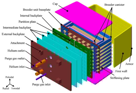
Figure 3.
Schematic view of the typical Helium-Cooled Solid Breeder (HCSB) blanket module.

Table 1.
Dimensions of the main parts of the typical HCSB outboard blanket module.
Table 2.
Material selections of the HCSB blanket.
Referring to literature [28], the detailed 3D neutronics model for the HCSB blanket is shown in Figure 4, and NWL of each blanket is shown in Figure 5. The equatorial outboard blanket (#12), of which the NWL (0.47 MW/m2) is maximum in all blankets, is selected to perform the coupling calculation. In the 1D cylinder neutronics model, the radial schemes of both inboard and outboard blanket are assumed to be the same as that of blanket #12. Figure 6 shows the radial layout of the neutronics model of the HCSB blanket.
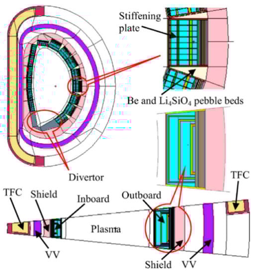
Figure 4.
China Fusion Engineering Test Reactor (CFETR) with the detailed HCSB neutronics model.
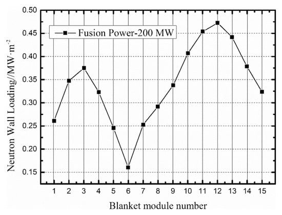
Figure 5.
Neutron Wall Loading (NWL) on each HCSB blanket.
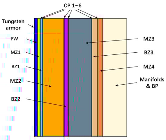
Figure 6.
Radial layout of the 1D HCSB neutronics model.
Figure 7 shows the main flows scheme of the helium coolant. To cool the HCSB blanket, the helium coolant is firstly pumped into the manifold #1 and distributed into the FW channels. After cooling the FW, the helium is gathered in the manifold #2 and flows into the top cap, bottom cap, and SP parallel. Then, the helium flows into the manifold #3 and is distributed into six CPs. To flatten the temperature distribution on the blanket, the flow directions in neighboring CPs are straggled. The helium flow directions in CPs are shown in Figure 8. Finally, the helium is collected in the the manifold #4 and flows out.
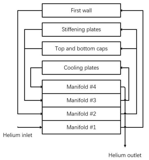
Figure 7.
Flow scheme of the helium coolant.
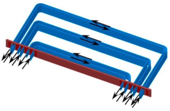
Figure 8.
Helium flow direction in the Cooling Plates (CPs).
Considering there are layer structures along the radial direction, it is reasonable to use the 2D model in the thermal-hydraulics calculation. Because the FW and BU occupy the most of the volume, the thermal performance of the blanket is largely determined by the FW and BU. Therefore, only the FW and BU are considered in the 2D thermal-hydraulics model. The other parts such as SPs and manifolds are ignored with a constant temperature in the neutronics calculation. A uniform surface heat flux of 0.3 MW/m2 from the plasma is applied as the FW boundary condition. The turbulent model is very critical to the TH analysis, however, the choice of the turbulent model is out of the scope of this paper. Although different models will lead to obvious different temperatures increasing, it does not influence the nature of the N/TH coupling effect. To simulate the turbulence, after careful comparison and reference [29,30] review, the shear stress transport (SST) turbulent model and the scalable wall function are adopted. Because the flow collection and distribution are difficult to simulate in the 2D model, the fluid fields in different parts are assumed independent with given boundaries conditions as listed in Table 3.
Table 3.
Boundaries conditions adopted in the thermal-hydraulics calculation.
Figure 9 shows the 2D thermal-hydraulics model of the HCSB blanket and the helium flow directions. To ensure that the simulation results are independent of the grid. The grid independent analysis is carried out based on the one-way N/TH coupling calculation. The most concerned variables in the N/TH coupling calculation include the coolant density and the material temperature. Therefore, the coolant densities at the outlets and the maximum temperature are selected to analyze. Three sets of grids, Grid #1, Grid #2, and Grid #3, are investigated, the element counts of which are 161,194, 477,527, and 954,127, respectively. Table 4 shows the results. It can be seen that the Grid #2 gives a grid independent result and the Grid #2 is chosen to perform the N/TH coupling calculation.
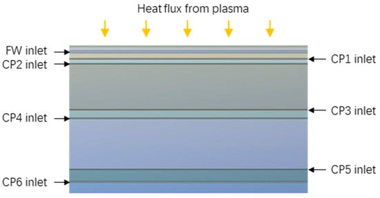
Figure 9.
The 2D HSCB thermal-hydraulics model.
Table 4.
Thermal-hydraulics results comparison of the HCSB with different grids.
2.3. WCCB Blanket Model
The conceptual design of the WCCB [31] blanket for the CFETR, based on the mature pressurized water reactor technology, was proposed by the Institute of Plasma Physics Chinese Academy of Sciences (ASIPP). Figure 10 shows the typical structure design of the WCCB blanket. The WCCB blanket is mainly composed of FW, mixing pebble beds, CPs, SPs, side walls (SWs), manifolds, and BP. The overall dimensions are 1199 mm (poloidal), 802 mm (radial), and 950 mm (toroidal), respectively. The FW is a U-shape structure along the radial-poloidal-radial directions. A layer with a thickness of 2 mm of tungsten armor covers on the FW to protect the FW from plasma corrosion and erosion. Forty-two channels with the cross section of 8 mm × 8 mm are arranged in parallel with the FW. To maintain chemistry stability, the WCCB adopts the mixing pebble beds consisting of Li2TiO3 and Be12Ti as the breeding material. Two layers of beryllium pebble beds are inserted to the BZ to enhance the neutron-multiplying capability. Light-water with a pressure of 15.5 MPa and inlet/outlet temperature of 285 °C and 325 °C is employed as the coolant. Main design parameters and material compositions of the WCCB blanket #3 are listed in Table 5 and Table 6.
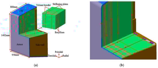
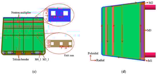
Figure 10.
The structure of the typical Water-Cooled Ceramic Breeder (WCCB) blanket: (a) Explosive view of the WCCB blanket; (b) Partially enlarged schematic; (c) Toroidal cross-section; (d) Poloidal cross-section.
Table 5.
Main parts dimensions of the WCCB blanket #3 module.
Table 6.
Material selections of the WCCB blanket.
According to literature [9], Figure 11 and Figure 12 show the 3D neutronics model and the NWL distribution of the blankets, respectively. The blanket #3, whose NWL is 0.454 MW/m2, is selected to perform the N/TH coupling analysis. Similar to the HCSB, the WCCB blanket model is simplified to a 1D cylinder neutronics model and a 2D thermal-hydraulics model for the N/TH coupling calculation. Figure 13 shows the radial layout of the 1D WCCB neutronics model.
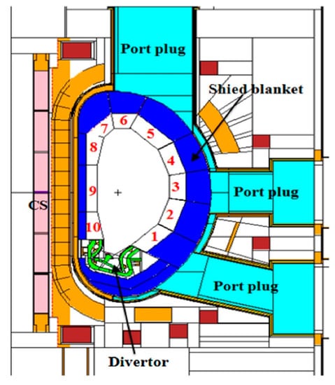
Figure 11.
Vertical cross section of the CFETR with the WCCB neutronics model.
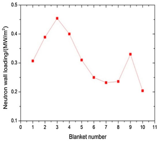
Figure 12.
NWL on each WCCB blanket module.
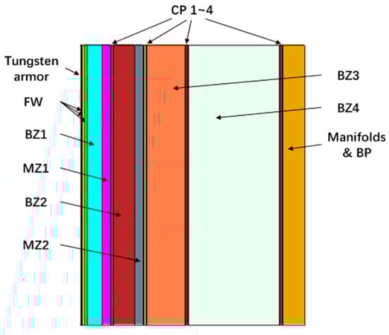
Figure 13.
Radial layout of the 1D WCCB neutronics model.
Figure 10b,d show the flow scheme of the water coolant. Channels between adjacent CPs are connected one by one. The water coolant, with the temperature to be 285 °C and with the pressure to be 15.5 MPa, comes from the blanket inlet. Firstly, the water coolant flows into the FW. Then, the water out of the FW channels goes through the CP #1 to the CP #4 in turn. The simplified 2D thermal-hydraulics model is shown in Figure 14.
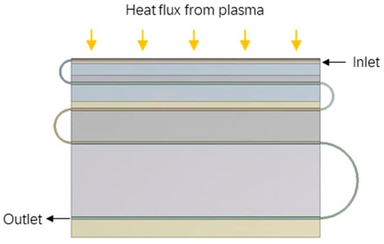
Figure 14.
The 2D WCCB thermal-hydraulics model.
In the thermal-hydraulics calculation, the heat flux to the FW is 0.3 MW/m2. To achieve an outlet temperature as the designed parameter, the mass flow rate is determined according to the total nuclear power deposition obtained from the one-way coupling calculation. In the thermal-hydraulics model, elbow pipes are assigned to connect channels for coolant transfer. The SST turbulent model is employed to deal with the phenomenon of boundary layer separation according to the recommendation of reference [32] at elbows. The results of the grid independent analysis are shown in Table 7. It can be seen that the differences are very small among the different grids. To save computational resources, the Grid #2 is chosen to perform the N/TH coupling calculation.
Table 7.
Thermal-hydraulics results comparison of the WCCB with different grids.
3. Results
3.1. The N/TH Coupling Calculation of HCSB Blanket
3.1.1. The Sensitivity Analyses of Temperature
Before performing the two-way N/TH coupling calculation, the sensitivity analyses of the material temperature of the neutron multiplier and the tritium breeder are carried out. It is helpful to understand how temperature affects the neutronics performance and explains the coupling results in the later section.
In particular, it should be noted that the cross sections data from S (α, β) tables which give a complete representation of thermal neutron elastic and inelastic scattering by molecules and crystalline solids in the neutron energies range below than 4 eV are not provided in the FENDL-2.1 library. Neutronic calculation without the S (α, β) will lead to an inaccurate TBR, because the thermal neutron has a considerable contribution to the TBR. Hence, the S (α, β) data from ENDF/B-VII.0 are used in this calculation.
Table 8 presents the calculation results without considering the S (α, β) data, and Table 9 presents the calculation results with considering the S (α, β) data. The situations of neutron multiplier and the tritium breeder at 20 °C, 327 °C, 627 °C, and 927 °C are calculated. The TBR and nuclear heat deposition are normalized to one source neutron.
Table 8.
Neutronics results of the HCSB blanket without considering the S (α, β) data at different materials temperatures.
Table 9.
Neutronics results of the HCSB blanket with considering the S (α, β) data at different materials temperatures.
From the comparison between the results at 20 °C in Table 8 and Table 9, it can be observed that the TBR is larger and the nuclear heat deposition is smaller with considering the thermal scattering treatment. When the S (α, β) data are not taken into account, there are only very small differences among the results at different temperatures, which is contrary to the reality. Thus, the S (α, β) data will make calculation results different, and should be considered in the N/TH coupling calculation.
From Table 9, the results reveal that the TBR is increasing as the beryllium temperature rises. Reason of this tendency is that, as the beryllium temperature increases, the neutron thermal scattering cross section increases, leading to more thermal neutrons. The total nuclear heat deposition decreases with the increasing of the temperature of the beryllium, and the changing rate decreases gradually. The reason is that the increases of the heat deposition in the breeder zones are less than the decreases of the heat deposition in the neutron multiplier zones. As for the temperature effects of Li4SiO4, TBR and nuclear heat deposition have a temporary rise between 20 °C and 327 °C, then remain stable. To sum up, TBR and nuclear heat deposition of the HCSB blanket will increase as temperature rises.
3.1.2. The N/TH Coupling Results
The coupling calculation begins with the neutronics calculation with a uniform temperature distribution of 20 °C. Table 10 lists the TBR, relative percentage standard deviation of TBR, and associated differences during the iteration process. The one-way N/TH coupling calculation is equal to the Iteration #0 in the two-way N/TH coupling calculation. The Iteration #2 is convergent. The TBR obtained from the two-way N/TH coupling calculation is 0.11% smaller than the one-way N/TH coupling calculation. As helium is transparent to neutron, the change of helium density will not impact neutronics results. Combined with the sensitivity analyses of the materials temperature, the two-way N/TH coupling effect should be mainly dominantly caused by the thermal scattering effect of the beryllium in the HCSB blanket. However, the more neutrons are absorbed by the steel at high temperature because of the Doppler-effect. As a result, the two-way N/TH coupling effect causes a small influence on TBR.
Table 10.
TBR variation in the two-way N/TH coupling calculation of the HCSB blanket.
As shown in Figure 15, the power density decreases along the radial direction in the zones with the same material. The nuclear heat power density of the tungsten armor is the maximum, because the high-energy neutron stream from the plasma directly penetrates the tungsten armor. Besides, the power densities are relatively high in BZs, and low in MZs. This is mainly determined by the high heat release cross sections of the tritium breeder. Figure 16 shows the relative differences of the power density between the two-way and one-way N/TH coupling calculations (one-way results are used as the reference values). There are very small differences between the one-way and two-way coupling calculations. Compared with the power densities obtained from the one-way N/TH coupling calculation, the power densities obtained from the two-way N/TH coupling calculation are overestimated in armor, MZ1 and BZ1, and underestimated in other zones. The power density in CPs increases, because the more neutrons are absorbed by the structural material at high temperature.
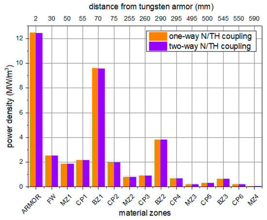
Figure 15.
Radial power density distribution of the HCSB blanket.
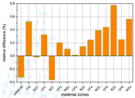
Figure 16.
The relative differences of the power density between the one-way and two-way N/TH coupling calculations.
Figure 17 shows the temperature distribution contour of the HCSB blanket obtained from the one-way coupling and two-way coupling calculations. Figure 18 shows the radial temperature distribution curve in the middle position of the poloidal direction of HCSB blanket obtained from the one-way and two-way coupling calculations, respectively. Obviously, the temperature changes greatly along the radial direction and changes slightly along the poloidal direction. Most nuclear heat is deposited in BZs due to the high power density and the high volume ratio. CPs are inserted into the interfaces between the BZ and the MZ. Therefore, the temperature curves in BZs and MZs show the cosine shape with the local maximum temperature appearing at the center. Because of the high nuclear heat deposition and the poor heat conductive capability of the tritium breeder, the global maximum temperature appears at the second BZ. Although there are a high heat flux and a high nuclear heat deposit in the tungsten armor and FW, the ample cooling capability ensures that the heat deposition in them could be removed so that the temperatures are kept at a low level.
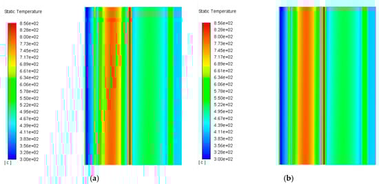
Figure 17.
Temperature distribution in the HCSB blanket: (a) one-way N/TH coupling calculation; (b) two-way N/TH coupling calculation.
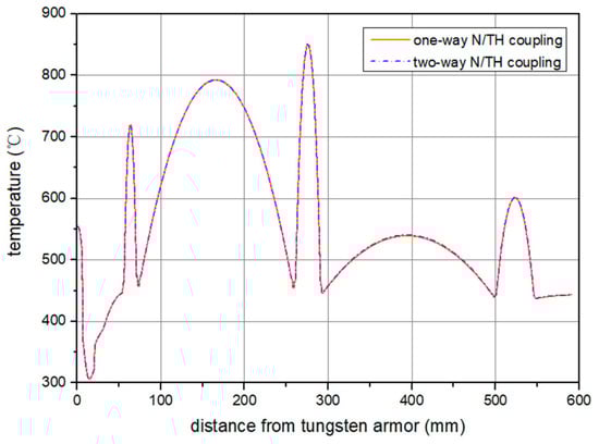
Figure 18.
Comparison of the temperature distribution along the radial direction.
Compared with the one-way N/TH coupling calculation, the temperature distribution obtained from the two-way coupling N/TH calculation increases in BZs and decreases in MZs. The nuclear heat deposition changes slightly. The temperature differences between the one-way and two-way N/TH coupling calculations are small, because the differences of the power density are small in most zones.
The relative power density changes in CPs are positive. As the thermal conductivity of CP is high and the heat power density changes are small, the temperature changes of the CPs are small. The maximum temperature difference appears at the fourth BZ, which is about 1 °C. It is concluded that the two-way N/TH coupling effect has a very small effect on the temperature distribution in the HCSB blanket.
3.2. The N/TH Coupling Calculation of WCCB Blanket
3.2.1. The Sensitivity Analyses of Temperature
Different from helium, light-water, which possesses the excellent neutron-moderating capability, will affect the neutron spectrum and generate more thermal neutrons in blanket. Considering the tritium production cross sections of the lithium are large in the low-energy ranges, the changes of density and temperature of water will obviously influence the TBR. To investigate and understand the temperature effect in different materials in the WCCB, the temperature sensitivity analyses of tritium breeder, neutron multiplier, and coolant are carried out. The temperatures of all materials are set to 20 °C firstly, and the density of water depends on its temperature. Because the saturated temperature of water is 345 °C with the pressure to be 15.5 MPa, only cases with 20 °C and 327 °C are calculated. The importance of the S (α, β) table was proven in the previous section, so the cases without considering S (α, β) are not calculated in this section.
Table 11 lists the calculation results. The variation tendencies of the neutron multiplier and the tritium breeder are similar to the HCSB. When the neutron multiplier temperature increases, the TBR increases, but the nuclear heat deposition decreases. Because the volume fraction of the neutron multiplier is small in the WCCB, the temperature effect has been diminished. Between 20 °C and 327 °C, the TBR and the nuclear heat deposition increase with the increase of the tritium breeder temperature. When the temperature of the tritium breeder is between 327 °C and 927 °C, the TBR and nuclear heat deposition remain stable.
Table 11.
Neutronics results of the WCCB blanket at different materials temperatures.
There is a noticeable increase in the TBR when the coolant temperature increases from 20 °C to 327 °C. The primary reason is that the density of water drops from 1.0 g/cm3 to 0.6 g/cm3. Although the neutron-moderating capability of water is weaker because of the low coolant density, more neutrons escape from the absorption of the coolant, and react with the breeder. Therefore, decreasing water density could effectively enhance the TBR.
3.2.2. The N/TH Coupling Results
The coupling calculation begins with the neutronics calculation with a uniform temperature of 20 °C. Table 12 lists the TBR and associated differences during the WCCB coupling iteration process. Iteration #0 means the one-way N/TH coupling calculation. After one iteration, the two-way N/TH coupling calculation is converged. Compared with the one-way coupling calculation, the coolant density is smaller, and the breeder temperature is higher in the two-way coupling calculation, hence the TBR increases by 4.45%. The influence of coolant temperature is significant. Moreover, there are more obvious impacts on the BZ, which is further away from the tungsten armor. It reveals that the two-way N/TH coupling effect has a significant impact in the WCCB blanket.
Table 12.
TBR variation in the two-way N/TH coupling calculation of the WCCB blanket.
As shown in Figure 19, the power density decreases along the radial direction in the zones with the same materials. The maximum nuclear heat power density appears at the tungsten armor. The power densities in the BZs are higher than the adjacent MZs. Figure 20 shows the relative differences of the power density distribution between the one-way and two-way N/TH coupling calculations. The power densities increase in BZs and MZs, and the relative differences increase more in the BZs, which are further away from the tungsten armor. It will lead to the temperature increase in the BZs and influence the safety of the blanket. The power density decreases in other zones. In the FW and CPs, there are great decreases in the relative power density differences between the one-way and two-way N/TH coupling calculations. This is mainly caused by the following two reasons: (1) when the coolant density decreases, the nuclear heat deposition in water decreases; (2) with the weaker neutron-moderating capability of the low-density water, fewer thermal neutrons are produced and absorbed by the steel. Therefore, the nuclear heat produced by steel decreases.
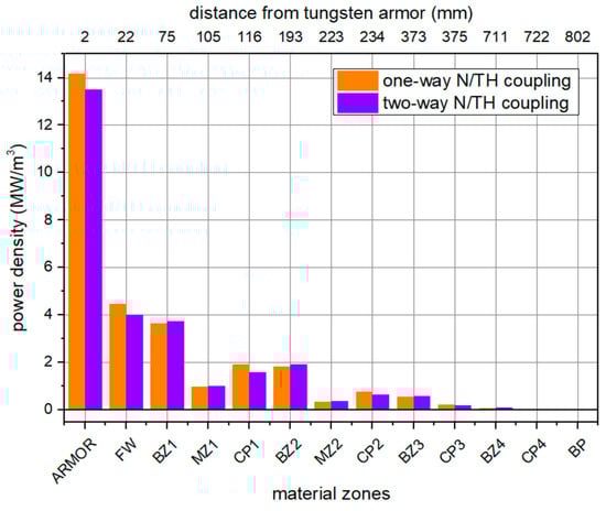
Figure 19.
Radial power density distribution of the WCCB blanket.
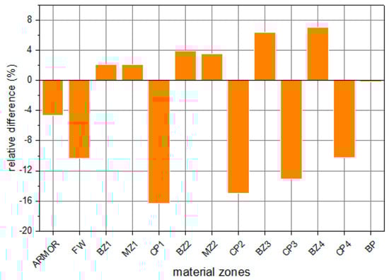
Figure 20.
The relative differences of power density between the one-way and two-way N/TH coupling calculations.
Figure 21 shows the temperature distribution contour of the WCCB blanket obtained from the one-way and two-way N/TH coupling calculations. Figure 22 shows the radial temperature distribution curve at the middle position of the poloidal direction. The temperature distributions of two calculations are similar: temperature changes greatly along the radial direction, and the local maximum temperature appears at the center of BZs. In the one-way N/TH coupling calculation, the maximum temperature is 960 °C, and appears at the center of the first BZ because of the maximum power density. In the two-way N/TH coupling calculation, the maximum temperature appearing at the central of the first BZ is 973 °C. Compared with the one-way N/TH coupling calculation, in the two-way N/TH coupling calculation, the maximum temperature increases in four BZs are 13 °C, 22 °C, 29 °C, and 26 °C, respectively. The ignorance of the two-way N/TH coupling effect may lead the temperature to exceed the temperature limit in the actual operation of CFETR. From the perspective of reactor safety, it is necessary to consider the two-way N/TH coupling effect in the blanket design.
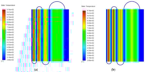
Figure 21.
Temperature distribution in the WCCB blanket: (a) one-way N/TH coupling calculation; (b) two-way N/TH coupling calculation.
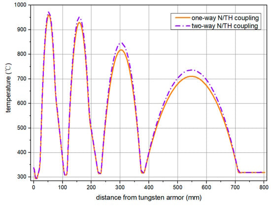
Figure 22.
Comparison of the temperature distribution along the radial direction.
4. Conclusions
In this paper, the two-way neutronics/thermal-hydraulics (N/TH) coupling effect in neutronics and thermal-hydraulics calculation results in the China Fusion Engineering Test Reactor (CFETR) blankets are investigated. Firstly, the 3D-1D-2D hybrid method and pseudo-material method are proposed to accelerate the N/TH coupling calculation based on the MCNP and FLUENT. Moreover, the sensitivity of the material temperature is analyzed to illustrate the mechanism of the two-way coupling N/TH effect. Furthermore, the one-way and two-way N/TH coupling calculations are carried out for the helium-cooled solid breeder (HCSB) blanket and the water-cooled ceramic breeder (WCCB) blanket. The conclusions of the two-way N/TH coupling effect in the CFETR blanket are as follows:
- Thermal scattering data in the S (α, β) table should be considered in the N/TH coupling calculation of the CFETR blanket.
- Increasing the temperature of beryllium could enhance the tritium breeding ratio (TBR), because the thermal scattering cross sections are large at high temperature.
- In the HCSB blanket, the two-way N/TH coupling effect will decrease the TBR by 0.11%, and increase the maximum temperature in BZ by 1 °C. The N/TH coupling effect could be ignored in the HCSB blanket.
- The TBR and nuclear heat deposition are sensitive to the temperature of water, because the density change induced by the temperature change will significantly impact the absorption and moderation capability.
- In the WCCB blanket, the two-way N/TH coupling effect is more significant. It will enhance the TBR by 4.45%, and increase the maximum temperature of the blanket by 29 °C.
- The relative change of the power density in steel is the largest among all materials in the coupling calculation. However, it will not affect the temperature distribution because the heat deposition could be removed effectively by the neighboring coolant.
- In general, the CFETR blankets are not so sensitive to the N/TH coupling effect. After only one iteration, the two-way N/TH coupling calculation is convergent. But from the viewpoints of accurate blanket design and safety analysis, it is still valuable to perform the two-way N/TH coupling calculation in fusion water-cooled blankets.
Author Contributions
Conceptualization, T.D.; methodology, T.D.; software, T.D., W.S.; formal analysis, T.D., W.S.; investigation, T.D.; resources, L.C.; data curation, T.D.; writing—original draft preparation, T.D.; writing—review and editing, Q.H., L.C., W.S.; visualization, T.D.; supervision, L.C., H.W.; project administration, L.C.; funding acquisition, L.C., Q.H. All authors have read and agreed to the published version of the manuscript.
Funding
This work was supported by the National Key Research and Development Program of China (No. 2017YFW0302200) and the Young Elite Scientists Sponsorship Program by CAST (No. 2019QNRC001).
Acknowledgments
The authors would like to express gratitude to Qixiang Cao, Zaixin Li, Fengchao Zhao, Shen Qu, and Bo Hu from Southwestern Institute of Physics for their valuable guidance in blanket calculation. The authors would also like to express gratitude to reviewers for kindly revising and constructive suggestions.
Conflicts of Interest
The authors declare no conflict of interest.
References
- Wan, Y. Design and strategy for the Chinese fusion engineering test reactor (CFETR). In Proceedings of the SOFE, San Francisco, CA, USA, 10–14 June 2013. [Google Scholar]
- Kim, Y.; Hong, B.G.; Kim, C.H. A neutronic investigation of He-cooled liquid Li-breeder blankets for fusion power reactor. Fusion Eng. Des. 2005, 75, 1067–1070. [Google Scholar] [CrossRef]
- Zhang, G.; Wu, H.; Cao, L.; Zheng, Y.; Li, Y.; Liu, Z. Study on the three-dimensional heterogeneous calculation of ITER test blanket module with deterministic method. Fusion Eng. Des. 2013, 88, 413–420. [Google Scholar] [CrossRef]
- Pereslavtsev, P.; Fischer, U.; Hernandez, F.; Lu, L. Neutronic analysis for the optimization of the advanced HCPB Breeder blanket design for DEMO. Fusion Eng. Des. 2017, 124, 910–914. [Google Scholar] [CrossRef]
- Palermo, I.; Fernandez, I.; Rapisarda, D.; Ibarra, A. Neutronic analyses of the preliminary design of a DCLL blanket for the EUROfusion DEMO power plant. Fusion Eng. Des. 2016, 109–111, 13–19. [Google Scholar] [CrossRef]
- Cho, S.; Ahn, M.Y.; Lee, C.W.; Kim, J.H.; Woo, M.H.; Park, J.S.; Im, K.; Lee, Y.; Park, Y.H.; Lee, D.W. Neutronic assessment of HCCR breeding blanket for DEMO. Fusion Eng. Des. 2019, 146, 1338–1342. [Google Scholar] [CrossRef]
- Li, Z.; Feng, K.; Zhao, Z.; Zhao, F.; Feng, Y.; Xu, K. Neutronics study on HCCB blanket for CFETR. Fusion Eng. Des. 2017, 124, 1273–1276. [Google Scholar] [CrossRef]
- Jaboulay, J.C.; Aiello, G.; Aubert, J.; Morin, A.; Troisne, M. Nuclear analysis of the HCLL blanket for the European DEMO. Fusion Eng. Des. 2017, 124, 896–900. [Google Scholar] [CrossRef]
- Moro, F.; Colangeli, A.; Del Nevo, A.; Flammini, D.; Mariano, G.; Martelli, E.; Mozzillo, R.; Noce, S.; Villari, R. Nuclear analysis of the Water cooled lithium lead DEMO reactor. Fusion Eng. Des. 2020, 160, 111833. [Google Scholar] [CrossRef]
- Kim, G.W.; Lee, J.H.; Cho, H.K.; Park, G.C.; Im, K. Development of thermal-hydraulic analysis methodology for multiple modules of water-cooled breeder blanket in fusion DEMO reactor. Fusion Eng. Des. 2016, 103, 98–109. [Google Scholar] [CrossRef]
- Di Maio, P.A.; Dell’Orco, G.; Furmanek, A.; Garitte, S.; Merola, M.; Mitteau, R.; Raffray, R.; Spagnuolo, G.A.; Vallone, E. Numerical simulation of the transient thermal-hydraulic behavior of the ITER blanket cooling system under the draining operational procedure. Fusion Eng. Des. 2015, 98–99, 1664–1667. [Google Scholar] [CrossRef]
- Li, M.; Chen, H.; Wang, S.; Liu, Q.; Zhou, G.; Ye, M. Optimization of coolant flow distribution for CFETR helium cooled solid breeder blanket. Fusion Eng. Des. 2015, 98–99, 1829–1832. [Google Scholar] [CrossRef]
- Jiang, K.; Ma, X.; Cheng, X.; Lin, S.; Huang, K.; Liu, S. Thermal-hydraulic analysis on the whole module of water cooled ceramic breeder blanket for CFETR. Fusion Eng. Des. 2016, 112, 81–88. [Google Scholar] [CrossRef]
- Martelli, E.; Caruso, G.; Giannetti, F.; Del Nevo, A. Thermo-hydraulic analysis of EU DEMO WCLL breeding blanket. Fusion Eng. Des. 2018, 130, 48–55. [Google Scholar] [CrossRef]
- Utoh, H.; Tobita, K.; Someya, Y.; Sato, S.; Seki, Y.; Takase, H. Development of a two-dimensional nuclear-thermal-coupled analysis code for conceptual blanket design of fusion reactors. Fusion Eng. Des. 2011, 86, 2378–2381. [Google Scholar] [CrossRef]
- Spagnuolo, G.A.; Chiovaro, P.; Di Maio, P.A.; Favetti, R. A multi-physics integrated approach to breeding blanket modelling and design. Fusion Eng. Des. 2019, 143, 35–40. [Google Scholar] [CrossRef]
- Jiang, K.; Ding, W.; Zhang, X.; Li, J.; Ma, X.; Huang, K.; Luo, Y.; Liu, S. Development of neutronic-thermal hydraulic-mechanic-coupled platform for WCCB blanket design for CFETR. Fusion Eng. Des. 2018, 137, 312–324. [Google Scholar] [CrossRef]
- Cui, S.; Zhang, D.; Lian, Q.; Tian, W.; Cheng, J.; Su, G.H.; Qiu, S. Development of a neutronics/thermal-hydraulic coupling optimization code and its application on the CFETR HCSB blanket. Fusion Eng. Des. 2017, 122, 140–153. [Google Scholar] [CrossRef]
- Cui, S.; Zhang, D.; Tian, W.; Su, G.; Qiu, S. Numerical research on the coupling optimization design rule of the CFETR HCSB blanket using NTCOC code. Fusion Eng. Des. 2018, 127, 234–248. [Google Scholar] [CrossRef]
- Jiang, K.; Zhang, X.; Li, J.; Ma, X.; Liu, S. Using one hybrid 3D-1D-3D approach for the conceptual design of WCCB blanket for CFETR. Fusion Eng. Des. 2017, 114, 57–71. [Google Scholar] [CrossRef]
- Conlin, J.L.; Ji, W.; Lee, J.C.; Martin, W.R. Pseudo Material Construct for Coupled Neutronic-Thermal-Hydraulic Analysis of VHTGR. Trans. Am. Nucl. Soc. 2015, 92, 225–227. [Google Scholar]
- Clarno, K.T.; Palmtag, S.; Davidson, G.G.; Salko, R.K.; Evans, T.M.; Turner, J.A.; Belcourt, K.; Hooper, R.; Schmidt, R. Coupled Neutronics Thermal-Hydraulic Solution of a Full-Core PWR Using VERA-CS. In Proceedings of the PHYSOR 2014, Kyoto, Japan, 28 September–3 October 2014. [Google Scholar]
- Kochunas, B.; Jabaay, D.; Collins, B.; Downar, T.J. Coupled thermal-hydraulics and neutronics calculations with COBRA-TF and MPACT. In Proceedings of the American Nuclear Society 2014 Annual Meeting, Reno, NV, USA, 15–19 June 2014. [Google Scholar]
- Guo, J.; Liu, S.; Shang, X.; Huang, S.; Wang, K. Coupled neutronics/thermal-hydraulics analysis of a full PWR core using RMC and CTF. Ann. Nucl. Energy 2017, 109, 327–336. [Google Scholar] [CrossRef]
- Liu, Z.; Wang, B.; Zhang, M.; Zhou, X.; Cao, L. An internal parallel coupling method based on NECP-X and CTF and analysis of the impact of thermal-hydraulic model to the high-fidelity calculation. Ann. Nucl. Energy 2020, 146, 107645. [Google Scholar] [CrossRef]
- Holtkamp, N.; The ITER Project Team. An overview of the ITER project. Fusion Eng. Des. 2007, 82, 427–434. [Google Scholar] [CrossRef]
- Chen, H.; Li, M.; Lv, Z.; Zhou, G.; Liu, Q.; Wang, S.; Wang, X.; Zheng, J.; Ye, M. Conceptual design and analysis of the helium cooled solid breeder blanket for CFETR. Fusion Eng. Des. 2015, 96–97, 89–94. [Google Scholar] [CrossRef]
- Arbeiter, F.; Gordeev, S.; Heinzel, V.; Slobodtchouk, V. Analysis of turbulence models for thermohydraulic calculations of helium cooled fusion reactor components. Fusion Eng. Des. 2006, 81, 1555–1560. [Google Scholar] [CrossRef]
- Gordeev, S.; Arbeiter, F. Validation study of turbulence models for thermal-hydraulic simulation of helium cooled DONES high flux test module. Fusion Eng. Des. 2020, 159, 111881. [Google Scholar] [CrossRef]
- Lv, Z.; Chen, H.; Chen, C.; Li, M.; Zhou, G. Preliminary neutronics design and analysis of helium cooled solid breeder blanket for CFETR. Fusion Eng. Des. 2015, 95, 79–83. [Google Scholar] [CrossRef]
- Liu, S.; Ma, X.; Jiang, K.; Cheng, X.; Huang, K.; Neilsion, H.; Titus, P. Conceptual design of the water cooled ceramic breeder blanket for CFETR based on pressurized water cooled reactor technology. Fusion Eng. Des. 2017, 124, 865–870. [Google Scholar] [CrossRef]
- Wang, W.H.; Li, J.L.; Liu, S.L.; Pei, X.; Huang, Q.Y.; FDS Team. Three-dimensional dual-flow fields analysis of the DFLL TBM for ITER. Fusion Eng. Des. 2012, 87, 989–994. [Google Scholar] [CrossRef]


© 2020 by the authors. Licensee MDPI, Basel, Switzerland. This article is an open access article distributed under the terms and conditions of the Creative Commons Attribution (CC BY) license (http://creativecommons.org/licenses/by/4.0/).