Article

Design and Performance Assessment of Multi-Use Offshore Tension Leg Platform Equipped with an Embedded Wave Energy Converter System

1
State Key Laboratory of Hydraulic Engineering Simulation and Safety, School of Civil Engineering, Tianjin University, Tianjin 300072, China
2
Key Laboratory for Mechanics in Fluid Solid Coupling Systems, Institute of Mechanics, Chinese Academy of Sciences, Beijing 100190, China
*
Author to whom correspondence should be addressed.
Energies 2020, 13(15), 3991; https://doi.org/10.3390/en13153991
Submission received: 13 May 2020 / Revised: 20 July 2020 / Accepted: 27 July 2020 / Published: 2 August 2020
(This article belongs to the Special Issue Renewable Energy Systems for Buildings)

Abstract

:
In this study, a new multi-use offshore tension leg platform (TLP) was designed for wave energy production through an embedded wave energy converter (EWEC) system. The proposed EWEC system consists of four built-in tuned liquid column dampers for absorbing the hull motion energy and eight Wells turbines as the power take-off devices. A multifold nonlinear analytical model of this multibody system was developed considering the hydrodynamics of the TLP-EWEC system during large motions and the aerohydrodynamics of the chamber-turbine groups. A comprehensive assessment, including an evaluation of motion responses and preliminary generating capacity, was performed for different wave-load directions using the numerical time integration method. The results indicated that the multi-use platform can generate a considerable amount of turbine power for the offshore platform energy mix as well as serve for offshore oil and gas production in the target oil fields. Such additional benefits and profitability were proven effective and worthy for further exploration and practical application.

Graphical Abstract

1. Introduction

Ocean waves contain a seemingly inexhaustible amount of energy, which can be both a source of destructive power for nearshore and offshore structures and a conspicuous source of renewable clean energy. With respect to the former, various types of marine structures that can withstand the ocean environment have been developed. These include ships for cargo transportation and offshore operations, platforms for marine resource exploitation, and buoys for environmental monitoring. On the other hand, the development of structures that allow for wave energy conversion and conservation on a commercial scale has been difficult, slow, and expensive [1].
Since Salter’s paper [2], there have been a number of initiatives and developments in the field of wave energy in various parts of Europe as well as the rest of the world. For instance, thousands of patents have been filed and many studies have been performed on the different ways of converting wave energy at different water depths and locations into a useful form [3]. Fixed or floating oscillating water columns (OWCs), oscillating body systems, and overtopping converters can be used. In addition, the power take-off (PTO) mechanism has also been proposed, including self-rectifying air turbines [4], (low- and high-head) water turbines, and (high-pressure oil-driven) hydraulic motors. A detailed review of the mechanical PTO equipment available for wave energy conversion can be found in Salter et al. [5].
Considering the purpose of the integration wave energy-offshore platform, the OWC mentioned above seems to have a great potentiality for its simple mechanics and flexibility [6]. In general, OWCs are based on wave-to-pneumatic energy conversion and utilize ocean waves to drive the motion of a water column within a semi-submerged pneumatic chamber. The movement of the water column causes bidirectional airflow and pressure fluctuations within the chamber. The pneumatic energy is then converted into mechanical energy by a turbine or other PTO system that is connected to a generator to transform the mechanical energy into electricity. Such devices can be categorized based on their location, onshore or nearshore fixed OWCs and offshore floating OWCs [7,8]. With respect to the former, numerous investigations have been performed over the past few decades, including analytical, experimental, and numerical studies [9,10]. Moreover, full-sized prototypes equipped with self-rectifying air turbines, generally still in the research and development phase, have been built in Norway, Japan, India, Portugal, the UK, and, more recently, in China [11]. On the other hand, offshore devices are more complex in terms of their hydrodynamic interactions and energy balance. Hence, there have been fewer experimental and numerical studies on these devices [12,13]. Further, there is a growing interest in multi-oscillating water columns (M-OWCs), which can be defined as an array of OWCs coupled together either in terms of their related structure, airflow, PTOs, or generators [14].
Based on the underlying principle of wave energy conversion, in this study, a new embedded wave energy converter (EWEC) system that can be attached to a tension leg platform (TLP) was developed. The EWEC system uses tuned liquid column dampers (TLCD) to absorb the energy from the hull motion resulting from the wave loadings, based on the sloshing of the working liquid. The fluctuation-free surfaces at the two ends of the working liquid column are similar to those of conventional OWCs. Therefore, with the installation of an air chamber and self-rectifying turbines above, the oscillating motion of the internal free surface generates an airflow through the turbine, which drives an electrical generator. This energy conversion chain of the TLP-EWEC coupled system can be simplified as follows: Wave motion - platform motion - liquid column oscillations - pneumatic oscillations - turbine rotation. As per this scheme, the conventional production platform would act as an energy-producing wave energy farm and contribute to the energy mix and even help achieve self-sufficiency in terms of electricity generation and consumption. On the other hand, the serviceability of the platform may be improved, as some of the hull motion energy is collected by the TLCDs. Brief descriptions of TLPs and TLCDs are given below.
TLPs are compliant offshore structures generally used for deep-water oil production or as floating foundations of offshore wind turbines. They consist of a semi-submersible-type floating platform that is attached to the sea bottom with vertical tethers, which are kept perpetually taut by the excess buoyancy of the platform. For the sake of linearity, studies on TLPs usually assume that all translational displacements and angular displacements are small in magnitude [15]. However, TLPs may experience distinctly large motions in certain sea states, and the attendant nonlinearity would affect their dynamic behavior. Therefore, the theoretical model proposed by Zeng et al. [16,17] was adopted in this study to consider the concomitant nonlinear factors induced by finite displacements. On the other hand, the evolution of offshore platforms has made it possible to think of other opportunities parallel to the traditional sole function. As a pioneer, the European Union launched “The Ocean of Tomorrow” [18], a call for proposals for multi-use offshore platforms in 2011. In 2014, Maribe launched the Horizon 2020 project [19] to determine if there is a future for investment in combining Blue Growth sectors. In 2018, two other projects, Space@Sea [20] and Blue Growth Farm [21], began. The former project intended to provide a sustainable and affordable workspace at sea, while the latter designs multipurpose offshore floating platforms that host aquaculture and energy harvesting. More related details can be found in the literature [22,23]. In fact, the existing multifunctional platforms are mainly in concept evaluation. To the best of our knowledge, there have been few reports on the combination of wave energy and offshore production platforms, let alone establishing dynamic models for performance assessment.
TLCDs are passive controlling devices used in building structures as auxiliary mass systems. Recently, TLCDs have attracted significant interest because of their numerous advantages, such as their low installation cost and simple maintenance requirements. Studies on TLCDs for buildings have ranged from investigations of their fundamental characteristics to evaluations of their control performance, optimization techniques, and control strategies [24]. In addition, the feasibility of using TLCDs with offshore systems, especially for offshore wind turbines, has also been explored by various researchers [25,26,27]. However, as is the case for TLP systems, there is a lack of deep research on the design issues related to TLCDs because of the difficulty in finding suitable co-locations for them [28,29]. Lee et al. [30] studied a TLP-TLCD system with three-DOF motions both analytically and experimentally. Lee et al. [31] developed an experimental testing method for investigating the vibration mitigation effect of a TLP system equipped with an underwater TLCD and subjected to surge wave motions. There have been few studies on the dynamic performance of such TLP-TLCD systems with six DOF. When a damper is used to suppress one DOF motion, its influence on the other DOF motions is very complex, and it is hard to simultaneously suppress motions with multiple DOF. In addition, there has been little research on the use of multi-TLCD systems (MTLCD) in offshore platforms. Some studies have suggested that MTLCD would be more advantageous as opposed to a single TLCD, owing to the detuning issues involved [32]. However, there have been no reports on the use of TLCDs in wave energy applications.
This manuscript is arranged as follows. A general description and a multifold nonlinear analytical model of the TLP-EWEC system are given in Section 2. In Section 3.1, the hydrodynamic interface model of the coupled system is validated, and a specific site was selected for detailed design. Next, the results of six-DOF motions and preliminary generating capacity of the system are discussed in Section 3.2 and Section 3.3. In Section 4, the comprehensive assessment of the coupled model and the prospect of such multi-use offshore platforms are discussed. Finally, Section 5 lists the primary conclusions of the study along with the future research directions.

2. Methods and Materials

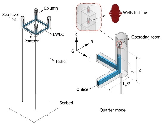
2.1. General Description of TLP-EWEC System

Figure 1 and Figure 2 show a TLP-EWEC system with typical buoyant members and built-in EWECs. The EWEC system consists of four TLCD devices (TLCD#1–4) with eight chamber-turbine groups (Tur#i-j, i = 1, 2, 3, 4 and j = 1, 2) and is placed symmetrically under the deck. For each TLCD, air chambers were built at the ends of the vertical columns, and Wells turbines were installed along the narrow ducts, which connect the air chambers to the outside atmosphere. Operating rooms were built for the operators for monitoring and handling. In addition, an orifice with a changeable orifice ratio (OR) was installed in the middle of the horizontal liquid column to switch the EWEC system on and off or vary the damping capacity of the TLCDs. All TLCDs used seawater as the working liquid and were equipped with a water pump system to adjust the volume of the working liquid inside.
As shown in Figure 3, the four main subsystems and their interconnections include the following:
  • The hydrodynamic subsystem is the TLP hull, which experiences the environment load and, hence, the vibrations.
  • The energy harvester subsystem consists of the TLCDs that absorb the hull motion energy based on the oscillations of the working liquid within them.
  • The PTO subsystem consists of the air chamber and self-rectifying turbines installed at the two ends of the TLCDs. This chamber-turbine module is the same as that used in common OWCs (i.e., M-OWCs).
  • The control subsystem is the intelligent part of the system, as it is responsible for the control of the TLP-EWEC system and its measurements. It mainly consists of an orifice and turbine controller, the relevant components for the automation and electromechanical processes.
The proposed multi-use design is a practical one for deep-water platforms sited a few hundred kilometers from the coast, because such a system can act as a wave energy farm and, thus, alleviate the high electrical load of offshore projects. The built-in EWEC system barely occupies any additional space. Moreover, it is suitable for complex marine environments where random waves come from different directions, owing to its symmetry. In addition, it is economical and efficient to adjust the liquid level in order to optimize the motion response and energy generation performance in the response to changes in the sea state. In a sense, the working liquid within acts as ballast water to ensure the safety of the offshore structures.

2.2. Governing Equations of Coupled TLP-EWEC System

In this section, the coupled three-dimensional governing equations for the TLP-EWEC system under large motions were derived using the D′Alembert-Lagrange equation [32]. While deriving the equations, three major hypotheses were made as follows [17,33]: (1) There was no relative motion between the TLP structure and the EWEC system, with the exception of that of the inner working liquid. (2) The TLP-EWEC system was idealized as a rigid body that can exhibit large motions. (3) The wave forces were evaluated using Morison’s equation with sufficient slender assumption. Further, the free surface effects were considered.
Assuming that o x y z is a fixed reference located on the undisturbed sea surface, the configuration of the TLP system at any instant of time can be described completely using the parameters X 1 , X 2 , and X 3 , which are the coordinates of the center of gravity (C.G.) of the TLP with respect to the global coordinate system, and the Euler angles ϕ , θ , and ψ , which define the sequence of rotations around the body axes, G ξ η ζ . As there is no relative motion between the main structure and the EWEC system, the body axes, G ξ η ζ , can also be used to describe the location and orientation of each TLCD in the TLP system. Assuming that all water particles inside TLCD#j (j = 1,…, 4) constitute a flexible body, an additional four independent coordinates H j (j = 1, …, 4) are needed to describe the relative motion of the liquid in G ξ η ζ with respect to its undisturbed state. Thus, the coupled system exhibits 10 DOFs in total and the vector of the TLP-EWEC system coordinates, q , can be written as follows:
q = [ q 1   q 2   q 3     q 10 ] T = [ X 1   X 2   X 3   ϕ   θ   ψ   H 1   H 2   H 3   H 4 ] T
The D′Alembert-Lagrange equation for the coupled system is given as follows:
d d t ( ( T U ) q ˙ ) ( T U ) q = Q e T
where Q e is the vector of the external forces and T and U are the total kinetic and potential energies and are given by,
T = T T L P + j = 1 4 T T L C D j , U = U T L P + j = 1 4 U T L C D j
The substitution of Equation (4) in Equation (2) yields the following equation:
d d t ( ( T T L P U T L P ) q ˙ ) ( T T L P U T L P ) q + j = 1 4 { d d t ( ( T T L C D j U T L C D j ) q ˙ ) ( T T L C D j U T L C D j ) q } = Q e T
It is obvious that the equations for the coupled system can be obtained once the equations for the TLP and TLCD subsystems in the current coordinate configuration have been determined. In this study, the mass of the airflow and turbines in the PTO subsystem were not taken into account; instead, we simply applied simultaneous forces and moments on the TLP structure and the corresponding TLCDs. We denoted the TLP subsystem using the superscripted numeral 0 while the TLCDs were denoted by the numerals 1 to 4 and the chamber-turbine groups by 5 to 8. Then, the governing equations in the matrix form can be gained after substituting related explicit terms in Equation (5) and written as,
[ M 0 + j = 1 4 M j ] { q ¨ } = [ Q 0 + j = 1 4 Q j + k = 5 8 Q k ] T
where Q j = Q e j + Q v j (j = 0, 1, 2, 3, 4), Q e j is the vector of the externally applied forces, including the hydrodynamic forces and buoyancy from the moving wave water and the tension from the tendons, and Q v j contains the rest of the force terms from the left side of Equation (5) after formalization. Further, Q k (k = 5, 6, 7, 8) represents the effects of the chamber-turbines on the TLP-EWEC system.
In the following sections, the equations for the TLPs are derived independently while the equations for the TLCDs are determined taking into account the interactions between the two subsystems. Then, the equations for the two subsystems are assembled as per Equation (5). The final dynamic equations are subsequently solved using the universal numerical method, that is, the explicit Runge-Kutta method [34].

2.2.1. Equations for Hydrodynamic Subsystem

In this section, we derive the nonlinear dynamic equations for the TLP system under large motions in the abovementioned coordinate system. Using Newton’s second law, the nonlinear six-DOF equations for the TLP system under large motions can be written as,
[ M 0 0 0 0 0 0 M 0 0 0 0 0 0 M 0 0 0 0 0 0 I 1 0 0 0 0 0 0 I 2 0 0 0 0 0 0 I 3 ] [ X ¨ 1 X ¨ 2 X ¨ 3 ω ˙ 1 ω ˙ 2 ω ˙ 3 ] = [ F 1 F 2 F 3 T 1 ( I 3 I 2 ) ω 2 ω 3 T 2 ( I 1 I 3 ) ω 3 ω 1 T 3 ( I 1 I 2 ) ω 1 ω 2 ]
where M is the body mass of a TLP, and I i (i = 1, 2, 3) are its moments of inertia with respect to the principal axes through its C.G. Further, T i and F i (i = 1, 2, 3) are the components of the external forces and moments, and ω i (i = 1, 2, 3) are the components of the angular velocity (see Equation (A1) in Appendix A).
The formulas for the components of the external forces and moments in Equation (6) can be found in Zeng et al. [16,17]. It should be noted that the added mass and drag force were included using the modified Morison equations [35]. By moving all the nonlinear functions for the acceleration to the left-hand side and the other terms to the right-hand side of the equations, Equation (6) can be written as a 10-DOF one, that is,
[ M 0 ] { q ¨ } = [ Q 0 ] T

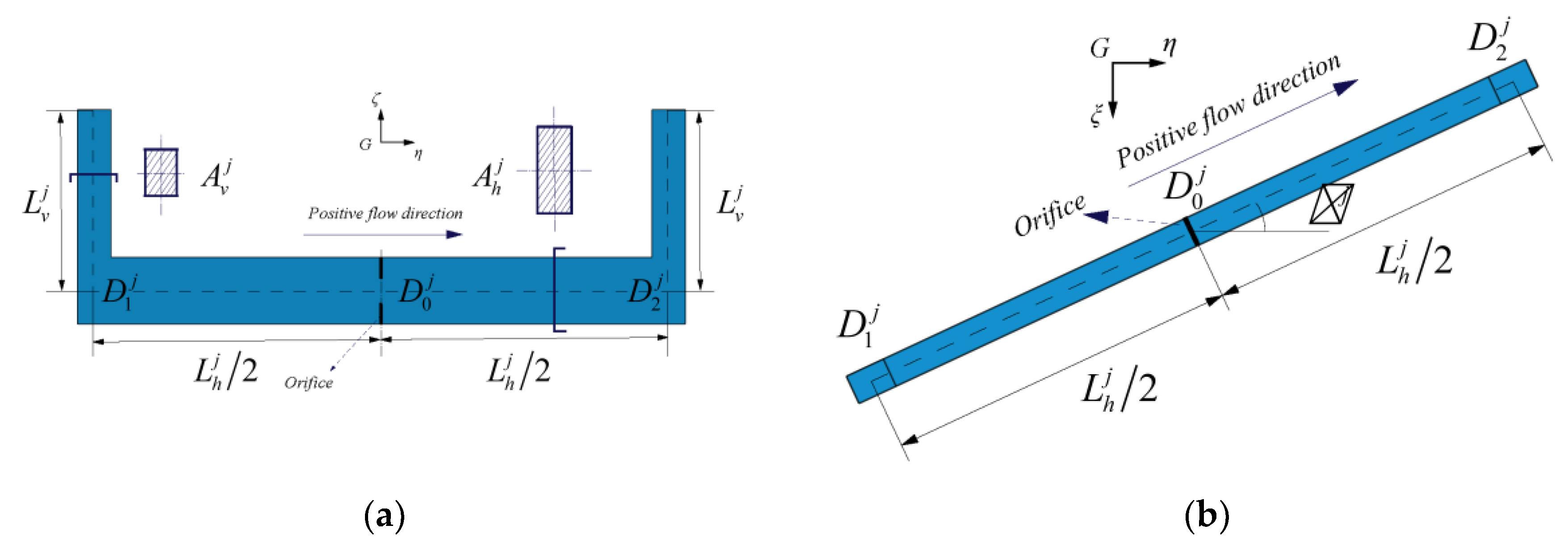
2.2.2. Equations for Energy Harvester Subsystem

For the TLCD, that is, TLCD#j, placed within the columns and pontoons, the positional information can be obtained from the central point, D 0 j , of the horizontal column and an arbitrary angle, α j , in the G ξ η ζ system. As shown in Figure 4, the bottom point, D 1 j , of the vertical column where the liquid level drops and the bottom point, D 2 j , of the vertical column where the liquid level goes up can be determined from point D 0 j , angle α j , and length of the horizontal column, L h j . The relationship of the three points is given as Equation (A2) in Appendix A.
The kinetic and potential energies of TLCD#j at an arbitrary position are given as
T T L C D j = n = 0 2 T T L C D n j , U T L C D j = n = 0 2 U T L C D n j
where n = 0, 1, 2, represents the horizontal columns, the vertical columns where the liquid drops, and the vertical columns where the liquid rises, respectively.
The absolute velocity of any microscale liquid column in the o x y z system can be expressed as
V P T = R · ( ω ¯ × r P + v H ) T + X T
where r P = ( ξ , η , ζ ) , v H = ( v H ξ , v H η , v H ζ ) is the relative liquid motion in the G ξ η ζ system, and R is the transformation matrix (see Equation (A5) in Appendix A).
Then, the kinetic energy can be obtained as
T T L C D j = L h j 2 L h j 2 1 2 ρ A h j [ V P 0 j ] T [ V P 0 j ] d l + 0 L v j H j 1 2 ρ A v j [ V P 1 j ] T [ V P 0 j ] d h + 0 L v j + H j 1 2 ρ A v j [ V P 2 j ] T [ V P 2 j ] d h
and the potential energy as
U T L C D j = L h j 2 L h j 2 ρ g A h j [ R 3 ] [ r P 0 j ] T d l + 0 L v j H j ρ g A v j [ R 3 ] [ r P 1 j ] T d h + 0 L v j + H j ρ g A v j [ R 3 ] [ r P 2 j ] T d h
where A h j and A v j are the cross-sectional areas of the horizontal and vertical TLCD columns, and R 3 is the third row of the transformation matrix R .
With respect to fluid flow in TLCDs, the loss of pressure or “head” occurs, owing to the fluid’s viscosity or changes in the cross-section and flow direction. When evaluating this loss, the total head resistance is defined by two different components, namely, the head resistance for the cross-sectional change along the channel and the head resistance because of the orifices [36].
F d j = 1 2 ρ ( A h j δ 1 j + ( A v j ) 2 A h j δ 2 j ) | H ˙ j | H ˙ j
where δ 1 j = ( 1 A v j A h j ) 2 + 0.5 | 1 A v j A h j | , δ 2 j = [ ( 1 k j ) + 0.707 ( 1 k j ) 0.375 ] 2 ( k j ) 2 , and k j is the OR for TLCD#j.
By substituting Equations (10), (11), and (12) into Equation (5), the equation for liquid motion within TLCD#j can be obtained in the matrix form as follows:
[ M j ] { q ¨ } = [ Q j ] T , j = 1 , 2 , , 4

2.2.3. Equations for Power Take-Off (PTO) Subsystem

In this section, a semitheoretical aerohydrodynamic model is established for the PTO subsystem. Based on experimental data, the equations [37] for the Wells turbine are
Δ p = C a K ( 1 / α ) [ V x 2 + ( r ω t ) 2 ]
T t = C t K r [ V x 2 + ( r ω t ) 2 ]
P t = ω t T t
where Δ p is the pressure drop across the rotor, T t is the turbine torque, K is a constant, a is the cross-sectional area, V x is the air-flow velocity, r is the mean radius, ω t is the turbine’s angular velocity, C a and C t are the power coefficient and the torque coefficient, respectively, given by experiments with respect to the flow rate, ϕ = V x / ( ω t r ) . The computing Matlab codes used can be found in the online Supplementary Materials.
With respect to the flow in the capture chamber, there are two main ways to simulate depending on whether or not the air compressibility is considered. The precise but complex model can refer to the approach of Henriques and Falcão [38] and Spanos and Federica [39]. Actually, the compressibility of air can be ignored in case the Mach number is less than 0.3 [40]. Moreover, the study on this topic by Bailey and Robertson [41] has shown that the influence of the incompressibility in terms of the difference in mean pneumatic, mechanical, and electrical power is very low (smaller than 0.79%). Thus, for the sake of having a fast and intuitive solution for WEC array modeling, we neglected the air compressibility. Then, the turbine volume flux is approximately equal to the volume flux of the fluid across the cross-section of the air chamber, and the air velocity in the turbine channel can be determined as
V x = A v a H ˙
In the present study, an ideal controller was employed for regulating the rotational speed of the turbine. The minimum speed of the turbines was preset, and the turbines accelerated or decelerated automatically. It should be emphasized that this control strategy was not designed for optimal power production but merely to maintain the turbine velocity within a desired range of values in order to prevent stalling and other problems. The mechanical and electrical losses were neglected, and the instantaneous turbine power was assumed to be equal to the instantaneous aerodynamic power.
Considering the air chambers to be hexahedrons whose bottom is the liquid surface and the remaining faces are fixed on the TLP, the resultant forces acting on the TLP structure and TLCD#j can be written as F j r = Δ p j r A v j e 3 and F j r = Δ p j r A v j e 3 , respectively. The interactional force on the TLP system would act at the position where the turbine is installed ( ξ t j r , η t j r , ζ t j r ) , and the moment resulting from the air pressure can be derived as
F t j r = R F j r , T t j r = ( ξ t j r , η t j r , ζ t j r ) × F j r
where ξ t j r and η t j r are the corresponding vertical liquid column coordinates in the G ξ η ζ system, and ζ t j r can be determined from the height of the turbines, Z h , shown in Figure 1.
The interactional force on TLCD#j is the result of the pressure drop between the right chamber and the left one (subscripted with jl) and is given as
F t j = | F j l | | F j r | = ( Δ p j l Δ p j r ) A v j
Finally, the generalized force, Q k (k = 5, …, 8), can be determined by assembling all the related equations based on their corresponding components (see Equation (A6) in Appendix A).

3. Results

3.1. Hydrodynamic Validation and Target Design

Due to the absence of design reference for similar systems, the International Ship and Offshore Structures (ISSC) TLP was used as the hydrodynamic subsystem with an assumption that the EWEC would not change the original mass distribution of the TLP. In other words, the TLP-EWEC system keeps the same hull design and mass distribution of the ISSC TLP before the TLCD filled with sea water. Considering the additional mass of the EWEC, the draught of the TLP-EWEC will significantly change and slack off the tethers, which ought to be pulled. Therefore, the length of mooring lines should be adjusted and the tether pretension remains the same. Primary parameters of the hydrodynamic subsystem are listed in Table 1.
In this study, Liuhua Oil Fields in the South China Sea were selected as the possible destination and its metocean data listed in Table 2 were used. Since the natural periods of the hull′s six-DOF motion were expected to be far away from the peak wave periods, we designed appropriate TLCDs to behave as if they were in resonance with the peak wave frequency in order to improve the energy-harvesting performance. The relationship is given as
T p = π 2 L e / g , L e = 2 L v + L h A v / A h
Moreover, the weight of each TLCD was set to approximately 3.0% of that of the TLP-EWEC system. The design parameters of the TLCDs are listed in Table 3 while those of the Wells turbine model are given in Table 4 [42,43].
The characteristic curves of the selected Wells turbine [42,43] are shown in Figure 5, where the x-axis represents the flow rate, ϕ . Based on these curves, the flow coefficient was used to determine the pressure drop, Δ p , and turbine torque, T t , according to Equations (14) and (15).
Using the known wave spectrum, the synthetic sea state was simulated with the random phase method [44]. The algorithm for the Monte Carlo simulations of the individual wave frequencies and their bandwidths was taken from Finnegan and Goggins [45]. To verify the computational procedure employed for the hydrodynamic calculations, six-DOF dynamic responses of the TLP in the case of regular waves (wave height = 8.0 m, wave period = 14 s) with a heading angle (HA) of 22.5° were compared with the existing solution [16,17], and it was found a good coincidence in Figure 6.

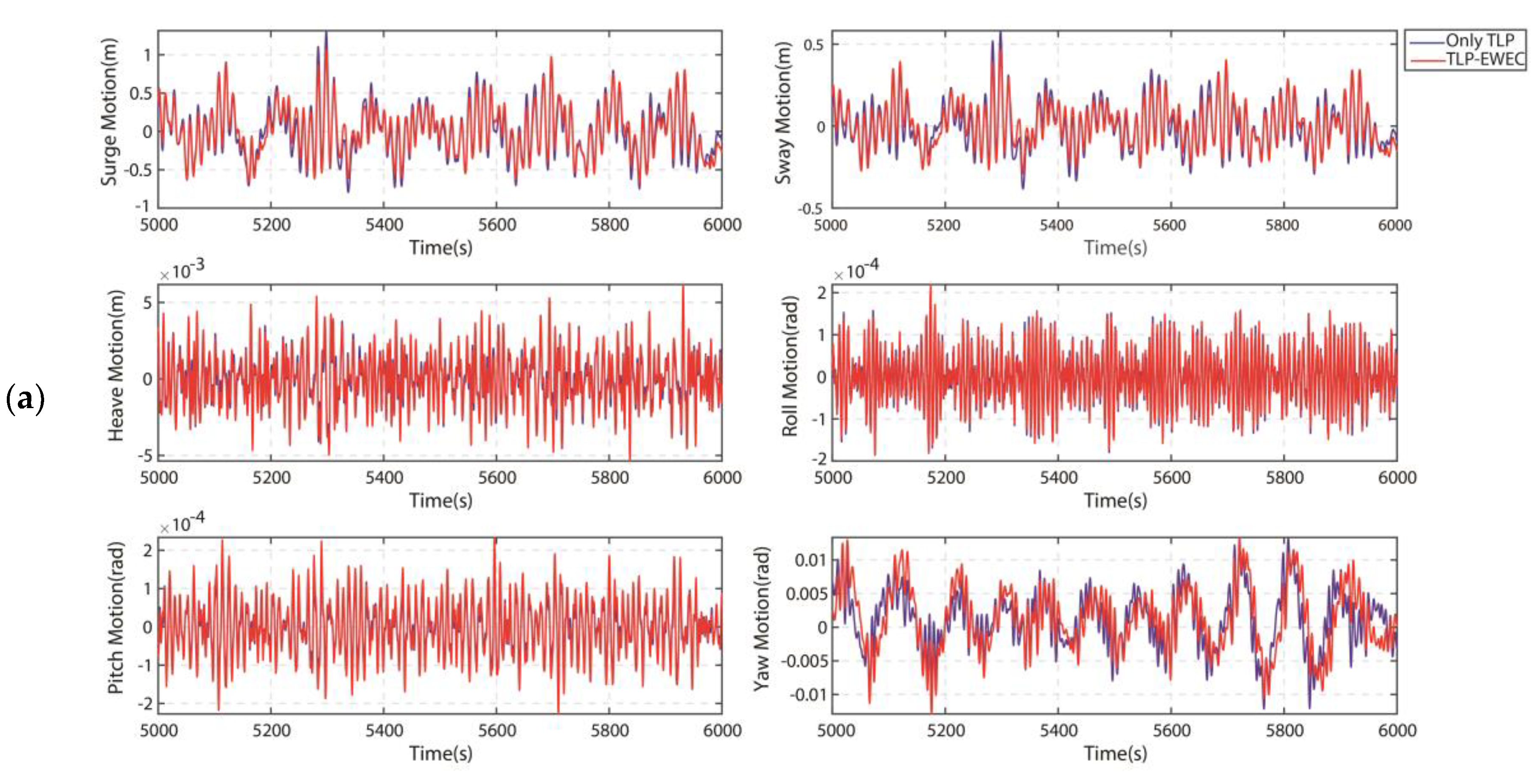
3.2. Hydrodynamic Performance Analysis

3.2.1. Comparison with the ISSC TLP System

The motion responses of the TLP-EWEC system were evaluated against the requirements for offshore production operations by comparing them with that of the ISSC TLP system. It should be noted that the design of the ISSC-TLP system was considered reliable and used as the reference for offshore operation requirements, even though there were differences in the drafts and weights of the ISSC TLP system and the TLP-EWEC system.
Figure 7 shows a comparison of the time series of the six-DOF motions and velocities of the TLP-EWEC system and the TLP system for an HA of 22.5°. It should be noted that the time window, 5000–6000 s, was selected after the six-DOF motions reached steady fluctuation within certain range. Another important consideration is that the length of the time window should be several times larger than the maximum characteristic period of the TLP hull, the TLCDs, and the waves. It can be seen that the motion trajectories were similar, owing to the fact that the wetted hull surfaces and structural symmetry-related characteristics of the two systems were similar. Further, the simulation results indicated that the TLP-EWEC system exhibited smaller responses in the case of the two horizontal translation DOFs; however, there were no obvious differences in the case of the other DOF. Similar results can be found in the published article [46], where the TLCDs are installed upon the platform deck rather than embedded within the pontoons and column for space efficiency (shown in Figure 1). For a more accurate analysis, the maximum amplitude and standard deviation ratios of the motion responses for waves with different directions are shown in Figure 8.
It is obvious that there was no response in the sway, roll, and yaw directions when the waves came in 0°. Further, there was no response in the yaw direction when the waves came in 45°. The surge and roll responses were consistent with the sway and pitch responses, respectively, when the waves came in 45°. This was because of the symmetry of the two systems. These characteristics of the hull motions were also observed in the other results and confirmed the validity of the theoretical model as well as that of the computational procedure used.
Figure 8 indicates that the surge and sway performances of the TLP-EWEC system were better than those of the ISSC TLP system, which exhibited distinctly smaller amplitudes and variations for all wave-heading angles. The heave direction is an important design parameter in the case of production platforms with top tension risers. As compared to the heave amplitudes for the TLP system, those of the TLP-EWEC system were slightly lower, by not more than 5%, for HA = 45° but increased by 10% or less for HA = 0° and 22.5°. The changes in the standard deviations’ ratios in the heave were similar but smaller than those of the heave amplitudes. Further, the increases in the roll and pitch responses were within 20% while the yaw responses were slightly lower by approximately 10%.

3.2.2. Hydrodynamic Stability for Different Orifice Ratios

Next, the results of the evaluation of the hydrodynamic stability of the TLP-EWEC system for different OR values are presented. A total of four operating conditions (OR = 0.00, 0.25, 0.50, and 0.75) were analyzed, and the results were compared to those with OR = 1.00 (see Section 3.2.1). An OR value of 0.00 refers to the state where the orifice is completely closed, and the working liquid within the TLCDs does not oscillate. It should be noted that an OR value of 0.0001 was substituted for OR = 0.00 in order to prevent convergence difficulties during the numerical calculations.
Figure 9a–c shows that the variations in the response amplitudes were within 5% when the OR value was decreased from 1.00 to 0.25. However, for OR = 0.00, the variations were larger, ranging from −30% to 10%. For OR = 0.00, the amplitude of the sway motion increased by 10% and that of the roll velocity decreased by 20% for HA = 22.5°. However, for HA = 45°, the amplitudes of the roll and pitch velocity decreased by nearly 30%. The analysis also showed that the variations in the responses, that is, the standard deviations, were relatively insensitive to the changes in the OR, with a change being noticed only for OR = 0.00. This was because there exists an inversely proportional relationship between the head resistance and the OR value, as shown in Equation (12).

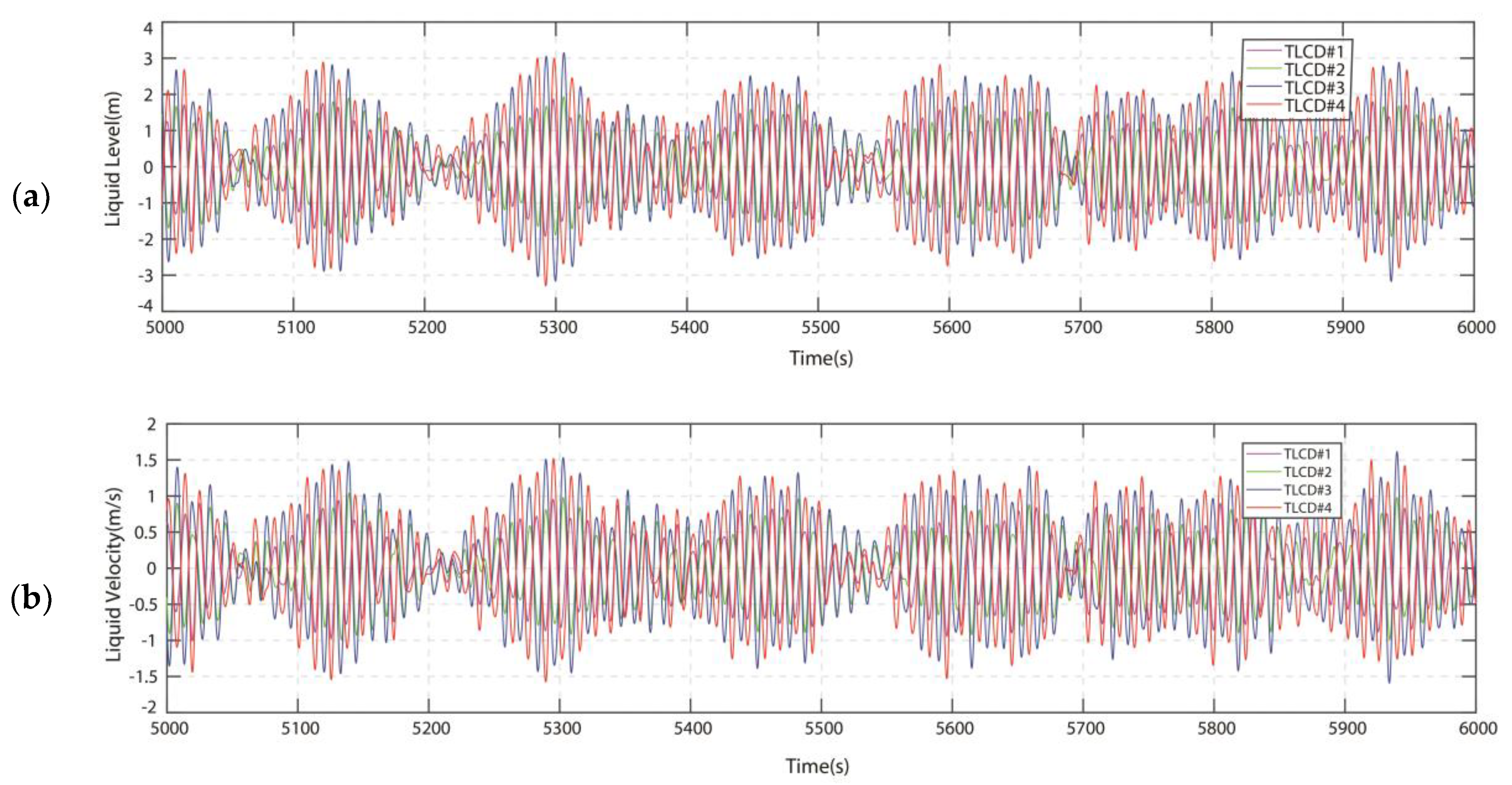
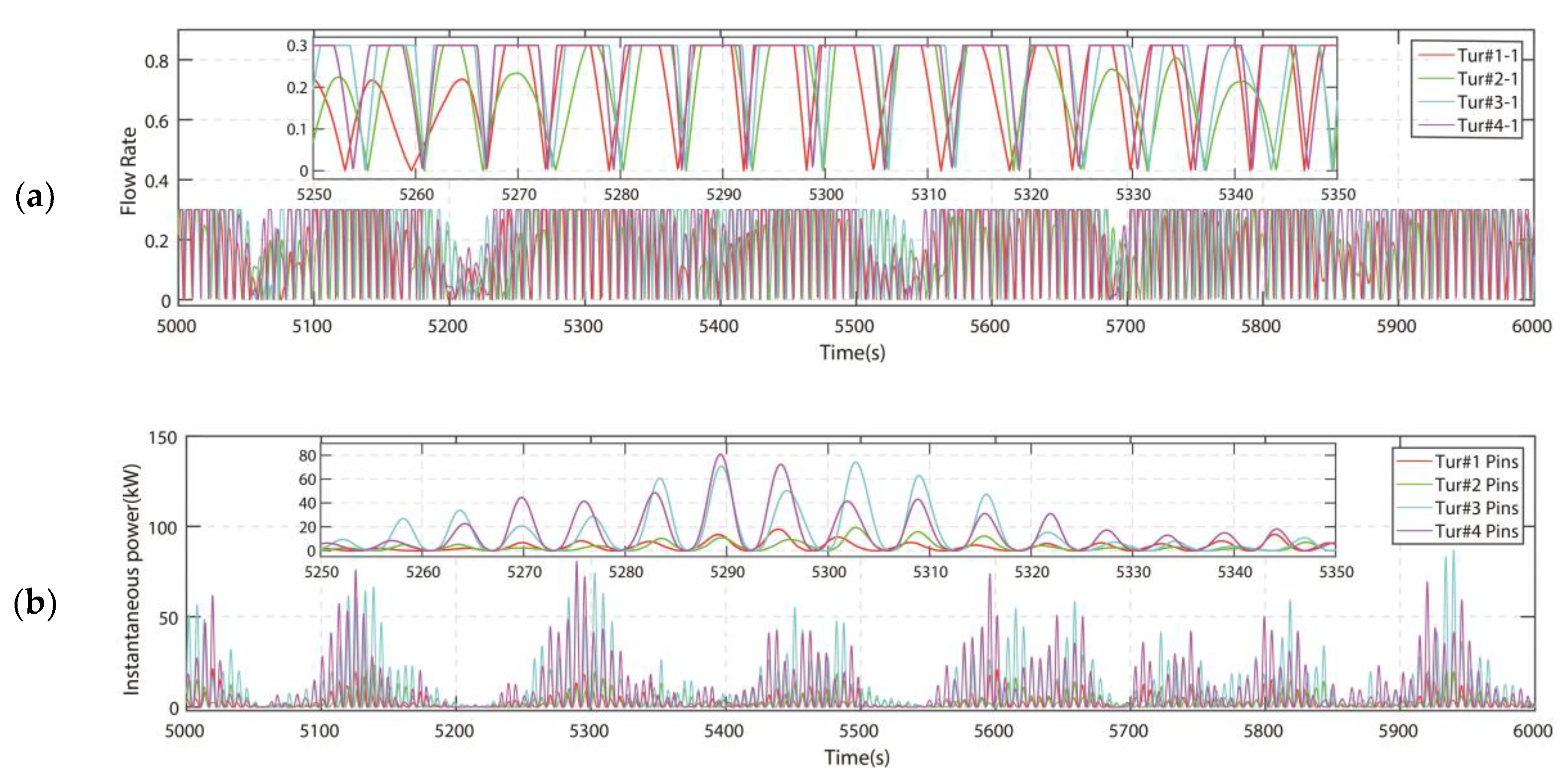
3.3. Generating Capacity of TLP-EWEC System

The effectiveness of the proposed TLP-EWEC system for energy generation was evaluated next. The dynamic response of the TLCDs equipped with the chamber-turbine modules in the case of waves coming in with HA = 22.5° is shown in Figure 10. Figure 10a,b is the water-column displacement and velocity time histories of TLCD#1 to TLCD#4. It can be seen that the TLCDs could capture the energy of the hull motion and cause the violent sloshing of the working liquid within. Interestingly, the motion and velocity of the working liquid were greater than those of the structure. This is because those TLCDs were designed in resonance with the peak wave frequency to fully excite internal liquid motion and improve the energy-harvesting performance. Over the observational time window, the liquid motion and velocity increased and decreased, in keeping with the intensity of the hull motion under the realistic sea conditions. Moreover, the response strength varied with the layout position of the TLCDs.
The variations in the flow rate and instantaneous power of Tur#i-1 (i = 1, 2, 3, 4) for the case where both ends of the working liquid were free of fluctuations are shown in Figure 10. For Tur#i-2 (i = 1, 2, 3, 4), the flow rate and instantaneous power were equal to Tur#i-1, respectively, because their instantaneous airflow velocities were of equal intensity but opposite directions with air incompressibility assumption. It can be observed that the flow rate, ϕ , became as high as 0.3, which corresponded to the threshold for the stalling of the turbines used, and maintained during a certain time owing to the turbine rotation controller. For evaluating the generating capacity, the instantaneous power of the turbine groups is the most important factor. In Figure 11b, the peaks and valleys in the cases of Tur#1 to Tur#4 can be seen clearly, with the power generated ranging from −169.8 W to 86.90 kW. Tur#1 refers to the sum of Tur#1-1 and Tur#1-2 for their equal instantaneous power. The same goes for other pairs of turbines. In addition, there were significant differences between the turbine groups as well, owing to the differences in the response strengths of the corresponding TLCDs. The sum of the instantaneous powers of the four turbine groups reached a maximum of 212.25 kW.
The performance of the TLCDs, maximum instantaneous power of the turbine groups, and average powers for different HA and OR values are shown in Figure 11. It can be seen that the structural symmetry of the proposed system resulted in symmetric responses in the cases of TLCD#1 to TLCD#4 (see Figure 12a). TLCD#1 and TLCD#2 did not oscillate at HA = 0°, while all the TLCDs exhibited symmetric motion at HA = 45°. Another reason is that the TLCD would be most efficient when its horizontal column is parallel to the excitation orientation but invalid if perpendicular. As the waves usually come from one main direction, the results can be used for optimization of the number and layout of TLCDs. The generating capacities of the turbine groups in response to the sloshing of the corresponding TLCD are shown in Figure 12b. For example, Tur#1 and Tur#2 did not output any power while Tur#3 and Tur#4 generated a considerable amount of electricity for HA = 0°. For HA = 22.5° and HA = 45°, all the turbines worked, and the output power was greater than that for HA = 0°. As described above, the instantaneous power will fluctuate greatly. Thus, the average power must be used for evaluating the generating capacity. It is not surprising that the average power of each turbine group was significantly lower than the instantaneous power, given the fluctuations. For OR = 1.0, the total average powers for HA = 0°, 22.5°, and 45° were 67.69 kW, 37.144 kW, and 52.52 kW, respectively. Fast estimation of the annual energy production (AEP) can be obtained by multiplying the average power level, the availability, and the yearly production hours:
A E P = P a v e × a v a i l a b i l i t y × h o u r s a n n u a l
where availability and hoursannual are indicatively assigned as 95% and 8766 h, respectively.
Therefore, the yearly energy production is significantly higher, ranging from 310 to 564 MWh/year with regard for wave heading angles, which may effectively contribute to the platform energy mix or even improve self-sufficiency in electricity consumption.
The OR has significant effects on the responses of the TLCDs and the generating capacity of the turbines. As the OR is decreased, the motion of the liquid within the TLCDs is suppressed greatly. Especially for OR = 0.25, the choking effect on the liquid is highly pronounced, resulting in a low generating capacity.

4. Discussion

In the results for the proposed TLP-EWEC system, in Section 3, the effectiveness of the multi-use design from the point of view of hydrodynamic responses and energy-generating capacity was presented. When the hydrodynamic responses of the TLP-EWEC and ISSC TLP, presented in Figure 7 and Figure 8, were compared, it was shown that the additional devices did not change the structural characteristic of such production platform, but improved several DOFs’ motion with limited deterioration on other DOFs. That is because there are difficulties in achieving six-DOF motion suppression just with TLCD devices for their passive energy-absorbing capacity [46]. Moreover, results in Section 3.2.2 proved that improvements can be expected in certain DOFs of the TLP-EWEC system and the deterioration in other DOFs is limited when the orifices are open completely or partially. Thus, it can be concluded that the TLP-EWEC met the requirements for offshore production operations as the ISSC-TLP if its EWEC system was switched on for energy generation.
Section 3.3 indicated that the TLP-EWEC system can generate a considerable amount of electric power and serve for offshore oil and gas production in the target oil fields. As the EWEC was designed in resonance with the peak wave frequency, the internal liquid motions were larger than the hydrodynamic hull and provided strong air flow for energy harvesting. For the selected three heading angles, HA = 0°, 22.5°, and 45°, the total average powers were 67.69 kW, 37.144 kW, and 52.52 kW, respectively (see Figure 12). Fast estimation of the AEP reported that the yearly energy production is significantly higher, ranging from 310 to 564 MWh/year, with regard for wave heading angles, which may effectively contribute to the platform energy mix or even improve self-sufficiency in electricity consumption. Moreover, given this effect of the OR on the response of the structure (in Section 3.2.2) and the generating capacity (in Figure 12), it can be extrapolated that the extents of the damping-related dissipation by the orifices and turbines are complementary. Therefore, the orifices can also act as protection devices to prevent the overloading of the turbine groups.
As per this multi-use design, the conventional production platform located a few hundred kilometers from the coast was able to act as an energy-producing wave energy farm. It can alleviate the high electrical load and even help achieve self-sufficiency in terms of electricity generation and consumption. On the other hand, the serviceability of the platform was improved, as some of the hull motion energy is collected by the EWEC. It must be mentioned here that in this paper only the TLP was used as the hydrodynamic hull preliminarily, but the concept can be spread to other types of offshore platforms (e.g., semisubmersibles and mono-column spars). Actually, the TLP structure has strict requirements of motions and would limit the productivity in calm sea conditions. Therefore, other type of platforms which permit greater movements during operations could excite the EWEC system more fully and it will be vastly more productive.

5. Conclusions

In this study, a preliminary design for an offshore TLP that combines a common offshore platform with a novel EWEC system was proposed for additional energy production function. To assess its feasibility, a multifold, nonlinear, analytical model of the coupled system was established for operation simulations and a specific site was selected for detailed design. The hydrodynamic computing program was validated and simulated the coupled system with different wave heading angles (HA = 0°, 22.5°, and 45°) and orifice ratios (OR = 0.00, 0.25, 0.50, 0.75, and 1.00), calculating both the six-DOF motions of the TLP hull and the power output of the EWEC system. We elaborated on the hydrodynamic behavior and generating capacity of the TLP-EWEC system. Based on the obtained results, the following conclusions can be drawn.
Firstly, the TLP-EWEC can serve for offshore production operations just as the ISSC-TLP, regardless of whether its EWEC system was switched on or off. The comparation of the six-DOF motions between the TLP-EWEC and the ISSC TLP indicated that the new design kept similar structural characteristics of such production platform and improved several DOFs motion with limited deterioration on other DOFs. Further investigation indicated that the hydrodynamic responses of the TLP-EWEC are insensitive to changes in orifice ratios.
Secondly, the assessment of generating capacity clearly showed that the TLP-EWEC system can generate a considerable amount of electric power in the target oil fields. The total average powers are 67.69 kW, 37.144 kW, and 52.52 kW for HA = 0°, 22.5°, and 45°, while the yearly energy production is ranging from 310 to 564 MWh/year. Additional benefits and profitability for the offshore platform energy mix and motion controlling were proven effective and worthy of further application.
Lastly, the TLP-EWEC design added new concepts for the next generation of offshore platforms and probed the possibility of wave energy sharing with oil and gas exploitation for offshore platforms. This scheme can be spread to other types of offshore platforms which permit greater movements during operations for higher energy production (e.g., semisubmersibles and mono-column spars). Moreover, the multifold, nonlinear, analytical model presented here can also help to overcome challenges in similar multi-use designs, primarily, among other benefits, the shared use of common offshore infrastructures.
It is clear that the TLP-EWEC has not been fully developed, gaps in research remain, and a remnant of potential outcomes can be investigated. Future research should be directed at the energy output/investment or levelized cost of energy (LCOE) of this new kind of WEC, the development of certain measures to tune the EWEC, or by combining the EWEC with other types of platforms for both high structural hydrodynamic performance and good energy-generating capacity.

Supplementary Materials

The computing Matlab codes used are available online at http://doi.org/10.5281/zenodo.3692833.

Author Contributions

Conceptualization, Y.Y. and Z.L.; methodology, Y.Y. and Z.L.; validation, J.Y., Z.L. and S.H.; formal analysis, Z.L., Y.F., and S.H.; investigation, Y.Y. and H.W.; writing—original draft preparation, Z.L., Y.C., and Y.Y.; writing—review and editing, Y.Y. and L.X.; supervision, J.Y. and Y.Y.; funding acquisition, L.X. and J.Y. All authors have read and agreed to the published version of the manuscript.

Funding

This research was funded by the National Natural Science Foundation of China (Grant no. 51779173), the National Key R&D Program of China (Grant no. 2018YFC0310502), and the Project of Ministry of Industry and Information Technology of China (Grant No. G18473CJ09).

Conflicts of Interest

The authors declare no conflict of interest.

Abbreviations

OWCOscillating water columnDOFDegree of freedom
PTOPower take-offMTLCDMulti-tuned liquid column damper
M-OWCsMulti-oscillating water columnsOROrifice ratio
EWECEmbedded wave energy converterC.G.Center of gravity
TLPTension leg platformISSCThe International Ship and Offshore Structures Congress
TLCDTuned liquid column damperHAHeading angle

Nomenclature

o x y z , G ξ η ζ Global fixed coordinate system and local coordinate system
X 1 , X 1 , X 3 , ϕ , θ , ψ Surge, sway, heave, roll, pitch, and yaw motion
H j Relative motion of liquid in TLCD#j
q Vector of the TLP-EWEC system coordinates
Q e Vector of external forces
T , T T L P , T T L C D j Kinetic energies of TLP-EWEC, TLP, and TLCD#j
U , U T L P , U T L C D j Potential energies of TLP-EWEC, TLP, and TLCD#j
M 0 , M j Final mass matrix of hull and TLCD#j
Q 0 , Q j , Q k Final force vector of hull, TLCD#j, and chamber#k
M Body mass of a TLP
ρ Density of sea water
I 1 , I 2 , I 3 Moments of inertia of a TLP
F , T External forces and moments on a TLP
( i , j , k ), ( e 1 , e 2 , e 3 )Axial base vectors of o x y z and G ξ η ζ
R Transformation matrix
r P = ( ξ , η , ζ ) Coordinates of microscale liquid column in G ξ η ζ
v H , V P T Relative motion and absolute velocity of microscale liquid column
ω ¯ Angular velocity of hull
F d j Total head resistance of TLCD#j
Δ p , T t , P t Pressure drop across the rotor, turbine torque, and turbine power
K , a , r Turbine constant, turbine cross-section area, and turbine mean radius
V x , ω t , ϕ Airflow velocity, turbine’s angular velocity, and flow rate
F j r , F j r , F j l , F j l Resultant forces acting on the TLP and TLCD#j due to air pressure
T t j r , T t j r , T t j l , T t j l Resultant moments acting on the TLP and TLCD#j due to air pressure
C a , C t Turbine power coefficient and torque coefficient
F t j Force on TLCD#j result from right and left chamber pressure difference
L h , A h Length and cross area of the horizontal liquid column
L v , A v Length and cross area of the vertical liquid column
T p , H s , γ Peak wave period, significant wave height, and peak enhancement factor

Appendix A

The angular velocity, ω ¯ , is given as
ω ¯ = [ ω 1 ω 2 ω 3 ] = [ ϕ ˙ cos θ cos ϕ + θ ˙ sin ψ ϕ ˙ cos θ sin ϕ + θ ˙ cos ψ ϕ ˙ sin θ + ψ ˙ ]
The relationship of those three points for TLCD#j is as follows
D 0 j : ( ξ 0 j , η 0 j , ζ 0 j ) D 1 j : ( ξ 1 j , η 1 j , ζ 1 j ) D 2 j : ( ξ 2 j , η 2 j , ζ 2 j )   ,   { ξ 1 j = ξ 0 j L h j 2 cos α j η 1 j = η 0 j L h j 2 sin α j ξ 1 j = ξ 0 j   ,   { ξ 2 j = ξ 0 j L h j 2 cos α j η 2 j = η 0 j L h j 2 sin α j ξ 2 j = ξ 0 j
Vectors r P and v H for each part of TLCD#j can be obtained as
r P 0 j = ( ξ 0 j + l cos α j , η 0 j + l sin α j , ξ 0 j ) , l [ L h j 2 , L h j 2 ] , r P 1 j = ( ξ 1 j , η 1 j , ζ 1 j + h ) , h [ 0 , L v j 2 H j ] , r P 2 j = ( ξ 2 j , η 2 j , ζ 2 j + h ) , h [ 0 , L v j 2 + H j ] .
v H 0 j = ( A v j A h j H ˙ j cos α j , A v j A h j H ˙ j sin α j , 0 ) , v H 1 j = ( 0 , 0 , H ˙ j ) , v H 2 j = ( 0 , 0 , H ˙ j ) .
The transformation matrix, R , is given as
R = [ cos θ cos ψ cos θ sin ψ sin θ sin ϕ sin θ cos ψ + cos ϕ sin ψ sin ϕ sin θ sin ψ + cos ϕ cos ψ sin ϕ cos θ cos ϕ sin θ cos ψ + sin ϕ sin ψ cos ϕ sin θ sin ψ + sin ϕ cos ψ cos ϕ cos θ ]
The generalized force, Q k (k = 5, …, 8), is assembled as
Q k = F t j r + F t j l + T t j r + T t j l + [ 0 0 0 F t j 0 0 ] 1 × 10 ( j = k 4 ) 1 2 k + 1 k + 2 k + 3

References

  1. López, I.; Andreu, J.; Ceballos, S.; De Alegría, I.M.; Kortabarria, I. Review of wave energy technologies and the necessary power-equipment. Renew. Sustain. Energy Rev. 2013, 27, 413–434. [Google Scholar] [CrossRef]
  2. Salter, S.H. Wave power. Nature 1974, 249, 720–724. [Google Scholar] [CrossRef]
  3. Pecher, A.; Kofoed, J.P. Handbook of Ocean Wave Energy; Springer International Publishing: Berlin, Germany, 2017; 20p. [Google Scholar]
  4. Cui, Y.; Liu, Z.; Zhang, X.; Xu, C. Review of CFD studies on axial-flow self-rectifying turbines for OWC wave energy conversion. Ocean Eng. 2019, 175, 80–102. [Google Scholar] [CrossRef]
  5. Salter, S.H.; Taylor, J.R.M.; Caldwell, N.J. Power conversion mechanisms for wave energy. Proc. Inst. Mech. Eng. Part M J. Eng. Marit. Environ. 2002, 216, 1–27. [Google Scholar] [CrossRef]
  6. Khan, N.; Kalair, A.; Abas, N.; Haider, A. Review of ocean tidal, wave and thermal energy technologies. Renew. Sustain. Energy Rev. 2017, 72, 590–604. [Google Scholar] [CrossRef]
  7. Melikoglu, M. Current status and future of ocean energy sources: A global review. Ocean Eng. 2017, 148, 563–573. [Google Scholar] [CrossRef]
  8. Gouaud, F.; Rey, V.; Piazzola, J.; Van Hooff, R. Experimental study of the hydrodynamic performance of an onshore wave power device in the presence of an underwater mound. Coast. Eng. 2010, 57, 996–1005. [Google Scholar] [CrossRef]
  9. López, I.; Pereiras, B.; Castro, F.; Iglesias, G. Performance of OWC wave energy converters: Influence of turbine damping and tidal variability. Int. J. Energy Res. 2015, 39, 472–483. [Google Scholar] [CrossRef]
  10. Ning, D.Z.; Wang, R.Q.; Zou, Q.P.; Teng, B. An experimental investigation of hydrodynamics of a fixed OWC Wave Energy Converter. Appl. Energy 2016, 168, 636–648. [Google Scholar] [CrossRef]
  11. Falcão, A.F.O.; Henriques, J.C.C. Oscillating-water-column wave energy converters and air turbines: A review. Renew Energy 2016, 85, 1391–1424. [Google Scholar] [CrossRef]
  12. Elhanafi, A.; Kim, C.J. Experimental and numerical investigation on wave height and power take–off damping effects on the hydrodynamic performance of an offshore–stationary OWC wave energy converter. Renew. Energy 2018, 125, 518–528. [Google Scholar] [CrossRef]
  13. Sheng, W. Motion and performance of BBDB OWC wave energy converters: I, hydrodynamics. Renew. Energy 2019, 138, 106–120. [Google Scholar] [CrossRef]
  14. Doyle, S.; Aggidis, G.A. Development of multi-oscillating water columns as wave energy converters. Renew. Sustain. Energy Rev. 2019, 107, 75–86. [Google Scholar] [CrossRef] [Green Version]
  15. Dhanak, M.R.; Xiros, N.I. Springer Handbook of Ocean Engineering; Springer: New York, NY, USA, 2016; 747p. [Google Scholar]
  16. Zeng, X.H.; Shen, X.P.; Wu, Y.X. Governing equations and numerical solutions of tension leg platform with finite amplitude motion. Appl. Math. Mech. 2007, 28, 37–49. [Google Scholar] [CrossRef]
  17. Zeng, X.; Liu, J.; Liu, Y.; Wu, Y. Parametric studies of tension leg platform with large amplitude motions. In Proceedings of the International Offshore and Polar Engineering Conference, Lisbon, Portugal, 1–6 July 2007; pp. 202–209. [Google Scholar]
  18. Koundouri, P.; Osiel, G. Investment Assessment of Multi-Use Offshore Platforms: Methodology and Applications. In The Ocean of Tomorrow; Springer International Publishing: Berlin, Germany, 2017; Volume 1. [Google Scholar]
  19. The Maribe H2020 Project. Available online: https://ec.europa.eu/research/participants/portal/desktop/en/opportunities/h2020/topics/bg-05-2014.html (accessed on 13 May 2020).
  20. Space@Sea. Available online: https://spaceatsea-project.eu/ (accessed on 13 May 2020).
  21. The Blue Growth Farm. Available online: http://www.thebluegrowthfarm.eu/ (accessed on 13 May 2020).
  22. Dalton, G.; Bardócz, T.; Blanch, M.; Campbell, D.; Johnson, K.; Lawrence, G.; Lilas, T.; Friis-Madsen, E.; Neumann, F.; Nikitas, N.; et al. Feasibility of investment in Blue Growth multiple-use of space and multi-use platform projects; results of a novel assessment approach and case studies. Renew. Sustain. Energy Rev. 2019, 107, 338–359. [Google Scholar] [CrossRef]
  23. Oliveira-Pinto, S.; Rosa-Santos, P.; Taveira-Pinto, F. Electricity supply to offshore oil and gas platforms from renewable ocean wave energy: Overview and case study analysis. Energy Convers. Manag. 2019, 186, 556–569. [Google Scholar] [CrossRef]
  24. El-Khoury, O.; Adeli, H. Recent Advances on Vibration Control of Structures under Dynamic Loading. Arch. Comput. Methods Eng. 2013, 20, 353–360. [Google Scholar] [CrossRef]
  25. Coudurier, C.; Lepreux, O.; Petit, N. Passive and semi-active control of an offshore floating wind turbine using a tuned liquid column damper. IFAC-PapersOnLine 2015, 48, 241–247. [Google Scholar] [CrossRef]
  26. Alkmim, M.H.; De Morais, M.V.G.; Fabro, A.T. Vibration Reduction of Wind Turbines Using Tuned Liquid Column Damper Using Stochastic Analysis. J. Phys. Conf. Ser. 2016, 744, 12178. [Google Scholar] [CrossRef]
  27. O’Donnell, D.; Murphy, J.; Desmond, C.; Jaksic, V.; Pakrashi, V. Tuned Liquid Column Damper based Reduction of Dynamic Responses of Scaled Offshore Platforms in Different Ocean Wave Basins. J. Phys. Conf. Ser. 2017, 842, 012–043. [Google Scholar] [CrossRef] [Green Version]
  28. Kandasamy, R.; Cui, F.; Townsend, N.; Foo, C.C.; Guo, J.; Shenoi, A.; Xiong, Y. A review of vibration control methods for marine offshore structures. Ocean Eng. 2016, 127, 279–297. [Google Scholar] [CrossRef]
  29. Zhang, B.L.; Han, Q.L.; Zhang, X.M. Recent advances in vibration control of offshore platforms. Nonlinear Dyn. 2017, 89, 755–771. [Google Scholar] [CrossRef]
  30. Lee, H.H.; Wong, S.H.; Lee, R.S. Response mitigation on the offshore floating platform system with tuned liquid column damper. Ocean Eng. 2006, 33, 1118–1142. [Google Scholar] [CrossRef]
  31. Lee, H.H.; Juang, H.H. Experimental study on the vibration mitigation of offshore tension leg platform system with UWTLCD. Smart Struct. Syst. 2012, 9, 71–104. [Google Scholar] [CrossRef]
  32. Shabana Ahmed, A. Dynamics of Multibody Systems, 3rd ed.; Cambridge University Press: Cambridge, UK, 2005. [Google Scholar]
  33. Kim, D.I.; Min, K.W.; Park, J.H.; Lee, H.R.; Kim, J.K.; Hwang, K.S.; Gil, Y.S. Tunable tuned liquid column dampers with multi-cells for wind vibration control of tall buildings. Proc. SPIE Int. Soc. Opt. Eng. 2012, 8345, 67. [Google Scholar]
  34. Dormand, J.R.; Prince, P.J. A family of embedded Runge-Kutta formulae. J. Comput. Appl. Math. 1980, 6, 19–26. [Google Scholar] [CrossRef] [Green Version]
  35. Chandrasekaran, S. Dynamic Analysis and Design of Offshore Structures; Springer: New Delhi, India, 2015; p. 5. [Google Scholar]
  36. Yalla, S.K.; Kareem, A. Optimum absorber parameters for tuned liquid column dampers. J. Struct. Eng. 2000, 126, 906–915. [Google Scholar] [CrossRef]
  37. El Marjani, A.; Castro Ruiz, F.; Rodriguez, M.A. Numerical modelling in wave energy conversion systems. Energy 2008, 33, 1246–1253. [Google Scholar] [CrossRef]
  38. Henriques, J.C.C.; Portillo, J.C.C.; Sheng, W. Dynamics and control of air turbines in oscillating-water-column wave energy converters: Analyses and case study. Renew. Sustain. Energy Rev. 2019, 112, 571–589. [Google Scholar] [CrossRef]
  39. Spanos, P.D.; Strati, F.M.; Malara, G. An approach for non-linear stochastic analysis of U-shaped OWC wave energy converters. Prob. Eng. Mech. 2018, 54, 44–52. [Google Scholar] [CrossRef]
  40. Liu, C. A tunable resonant oscillating water column wave energy converter. Ocean Eng. 2016, 116, 82–89. [Google Scholar] [CrossRef]
  41. Bailey, H.; Robertson, B.R.; Buckham, B.J. Wave-to-wire simulation of a floating oscillating water column wave energy converter. Ocean Eng. 2016, 125, 248–260. [Google Scholar] [CrossRef]
  42. Amundarain, M.; Alberdi, M.; Garrido, A.J. Neural rotational speed control for wave energy converters. Int. J. Control. 2011, 84, 293–309. [Google Scholar] [CrossRef]
  43. Amundarain, M.; Alberdi, M.; Garrido, A.J. Modeling and simulation of wave energy generation plants: Output power control. IEEE Trans. Ind. Electron. 2011, 58, 105–117. [Google Scholar] [CrossRef] [Green Version]
  44. Kim, M.H. Hydrodynamics of Offshore Structures. Dev. Offshore Eng. 1999, 336–381. [Google Scholar]
  45. Finnegan, W.; Goggins, J. Numerical simulation of linear water waves and wavestructure interaction. Ocean Eng. 2012, 43, 23–31. [Google Scholar] [CrossRef] [Green Version]
  46. Zeng, X.; Yu, Y.; Zhang, L. A New Energy-Absorbing Device for Motion Suppression in Deep-Sea Floating Platforms. Energies 2014, 8, 111–132. [Google Scholar] [CrossRef] [Green Version]
Figure 1. General view and quarter model of a TLP-EWEC system in static equilibrium position.
Energies 13 03991 g001
Figure 2. Arrangement plan of a TLP-EWEC system (planform).
Energies 13 03991 g002
Figure 3. Design breakdown of TLP-EWEC system following that of WEC system [3].
Energies 13 03991 g003
Figure 4. Schematic of TLCD: (a) Front view, (b) plan view.
Energies 13 03991 g004
Figure 5. Representative characteristics curves: (a) Torque coefficient vs. flow coefficient, (b) power coefficient vs. flow coefficient.
Energies 13 03991 g005
Figure 6. Dynamic responses of ISSC TLP along six DOF.
Energies 13 03991 g006
Figure 7. Comparison of motion responses of the TLP-EWEC system (with EWEC system turned on (OR = 1.0) and conventional TLP system for HA = 22.5°: (a) Six-DOF motions, (b) six-DOF velocities.
Energies 13 03991 g007aEnergies 13 03991 g007b
Figure 8. Motion responses of TLP-EWEC system (with EWEC system turned on (OR = 1.0) and conventional TLP system for different wave-heading angles.
Energies 13 03991 g008
Figure 9. Motion mitigation performances for different OR values: (a) HA = 0°, (b) HA = 22.5°, (c) HA = 45°.
Energies 13 03991 g009
Figure 10. Liquid response in EWEC system at HA = 22.5°: (a) Liquid level history, (b) liquid velocity history.
Energies 13 03991 g010
Figure 11. Turbine performances at HA = 22.5°: (a) Flow rate history, (b) instantaneous power history.
Energies 13 03991 g011
Figure 12. Liquid motion and energy generation performance of EWEC system for different HA values: (a) Liquid level (LL) and liquid velocity (LV), (b) instantaneous power (Pins) and average power (Pave).
Energies 13 03991 g012aEnergies 13 03991 g012b
Table 1. Primary parameters for the ISSC TLP and TLP-EWEC system.
ParameterISSC TLPTLP-EWEC
Column spacing between centers, L p (m)86.2586.25
Column diameter (m)16.8816.88
Pontoon width, L p w (m)7.507.50
Pontoon height, L p h (m)10.5010.50
Draft, h 0 (m)35.0040.84
Displacement (m)5.346 × 1055.346 × 105
Total tether pretension (m)1.373 × 1051.373 × 105
Platform mass, M T L P (m)40.5 × 10640.5 × 106
Roll mass moment of Inertia, I 1 (m)82.37 × 10982.37 × 109
Pitch mass moment of Inertia, I 2 (m)82.37 × 10982.37 × 109
Yaw mass moment of Inertia, I 3 (m)98.07 × 10998.07 × 109
Vertical position of COG above Keel, h G (m)38.038.0
Length of Mooring tethers, L (m)415.0409.16
Vertical stiffness of combined tethers, ES/L (kN/m)0.813 × 1060.813 × 106
Table 2. Metocean parameters.
Spectrum Peak   Enhancement   Factor ,   γ Significant   Wave   Height ,   H s Peak   Wave   Period ,   T p
JONSWAP2.46.5 m12.3 s
Table 3. Primary particulars of TLCDs.
ParameterValue
Length of the horizontal liquid column, L h 75
Height of vertical liquid column, L v 7.6
Cross area of the horizontal liquid column, A h (m)15
Cross area of the vertical liquid column, A v (m)12
ξ -coordinate of those TLCDs, { ξ 10 , ξ 20 , ξ 30 , ξ 40 } (m){−43.125, 43.125, 0, 0}
η -coordinate of those TLCDs, { η 10 , η 20 , η 30 , η 40 } (m){0, 0, −43.125, 43.125}
ζ -coordinate of those TLCDs, { ζ 10 , ζ 20 , ζ 30 , ζ 40 } (m){−32.75, −32.75, −32.75, −32.75}
α -laying angle of those TLCDs, { α 1 , α 2 , α 3 , α 4 } {π/2, −π/2, π, 0}
Table 4. Parameters of the Wells turbine.
Turbine Constant, KCross-Sectional Area, aTurbine Radius, r Installation   Height ,   Z h
0.70791.1763 m20.7285 m60 m

