1. Introduction
Nowadays, many researchers are focused on developing and implementing systems dedicated to micro-scale installations powered by renewable energy sources [
1]. In the wide field of climate change, it is necessary to seek alternative fuels, which can be more friendly for the environment [
2]. Among other options, cogeneration and trigeneration systems powered by biomass-fired devices are considered [
3]. In biomass powered micro-scale applications, the most popular fuels are wood and waste from its processing, straw, plants from energy crops, and agricultural products. The most popular micro-cogeneration technologies are solutions based on the use of the organic Rankine cycle (ORC) [
4], Stirling engines (SE) [
5], and thermoelectric generators (TEG) [
6]. There are also known hybrid systems integrating different micro-cogeneration technologies [
7]. The worldwide literature consists also of a few examples of micro-scale systems according to the Clausius–Rankine cycle [
8]. The selection of proper micro-cogeneration technology depends on the construction and operational parameters of the heat source and the expected level of electricity generation. This requires an original approach for designing and developing individual combined heat and power systems (CHP).
As it is known, biomass may be converted to electricity in the process of its gasification and combustion. The most commonly used biomass-fired devices in the residential sector are multi-fuel boilers, pellet-burning boilers, wood-fired gasification boilers, and wood-fired stoves. On the other hand, in the cases of, e.g., farms and housing estates, the application of straw-fueled batch boilers is becoming increasingly popular because straw is inexpensive and widely available fuel. The power range of different biomass-fired units is from a few kilowatts to megawatts.
This paper is focused on the presentation of practical possibilities to introduce power generation to two different types of biomass-fired devices: the 100 kWt straw-fired batch boiler and the 8–16 kWt wood-fired steel stove. Based on the preliminary analysis, two cogeneration technologies were selected, taking into account construction parameters of the considered batch boiler and stove, and available temperature and power, which may be obtained from these devices.
The approach presented is original—the devices we analyzed are not widely studied in the context of combined heat and power generation (especially batch boiler). Moreover, the proposed configuration of the micro-cogeneration system with a batch boiler is characterized by several unique solutions that distinguish the developed system from the classic Rankine cycle. In both analyzed systems, a dedicated control and measurement system and dedicated control algorithm were used.
Some examples of research devoted to thermoelectric generators involved stoves and systems operating according to the Rankine and organic Rankine cycles are presented below.
1.1. Thermoelectric Generators Operating with Stoves
There were several studies devoted to thermoelectric generators incorporated with domestic stoves. An example of the air-cooled thermoelectric module fitted to the domestic woodstove has been presented in [
9]. The maximum matched load power was obtained at a level of 4.2 W
e. Another example of a complete system with a multifunctional stove, thermoelectric generators, and other equipment was studied in [
10]. The maximum power available for the end-users was in that case ca. 7.6 W
e. On the other hand, in [
11] a forced water cooling system was studied (as a heat source an electric heater was used). The maximum observed power was ca. 10 W
e. Both air and water-cooled thermoelectric modules were tested and compared in [
12]. The maximum output voltage of the studied single TE module was ca. 6.1 V (in case of water cooling) compared to ca. 4.2 V and ca. 2.6 V when air cooling systems were used (forced air and natural respectively). In [
13] the possibility of applying the market-available TEGs to a stove was presented. The proposed system was used both for heating the water and charging a lead-acid battery. It was producing an average of 600 W
t and 27 W
e. In [
14] it was shown that connecting 600 thermoelectric modules in series may result in power at a level of 1 kW
e. Besides the use of TEGs in domestic mCHP systems, many studies include examples of the other TEGs applications: in automotive, aircraft and vessel sectors, microelectronics, micro-scale systems powered by solar energy and the space industry [
15].
1.2. Systems Operating According to Rankine and Organic Rankine Cycles
An example of a micro-cogeneration system with a single-stage piston engine operating according to the Clausius–Rankine cycle was investigated in [
16]. The thermal power of the system was 104 kW
t, while the electrical power was 23 kW
e. The electrical and total efficiency of this system was respectively ca. 14% and ca. 78%. Three ways of controlling the steam engine operation were tested: engine operation with variable shaft speed at constant shut-offs, engine operation with variable shut-offs at constant shaft speed and engine operation controlled by a steam pressure regulating valve. In [
17], the possibilities of using the Clausius–Rankine multi-stage system to improve the efficiency of the combined heat and electricity production process were discussed. On the other hand, the example of the ORC system powered by the biomass boiler was studied in [
18]. The electricity output of that system was ca. 2 kW
e, and electrical efficiency was ca. 7.5–13.5%. Another example is an experimental ORC system powered by a 50 kW
t pellet-fired boiler. In this case, the maximum electrical power was observed at a level of 860 W
e [
19]. Besides the performance analysis of micro-scale CHP systems, detailed analyses of CHP systems components were carried out (e.g., analyses of turbines [
20] and heat exchangers constructions [
21]). Moreover, some dynamic simulations devoted to biomass and solar CHP systems were conducted [
22]. Among other works, thermoeconomic analysis of an organic Rankine cycle powered by medium-temperature heat sources [
23] and analysis of an integrated system for sewage sludge drying [
24] were performed.
The remainder of the paper includes the investigations performed on two prototypical systems, which are currently being developed at AGH UST in Krakow (Poland): (i) a wood-fired stove with a thermoelectric generator and (ii) a straw-fired batch boiler a with steam-condensate circuit operating according to modified Rankine cycle.
2. Materials and Methods
The investigations were carried out using two dedicated experimental rigs. Control and measurement systems were based on the use of programmable logic controllers (PLC) operating with a set of dedicated sensors, transducers, and actuators. The idea of the studies was to develop and test micro-cogeneration units powered by two different biomass-fired units (8–16 kWt domestic stove and a 100 kWt batch boiler). Due to the large difference in power generated by both devices, two technologies of combined heat and power generation were considered. Consequently, below the descriptions and results are divided into two parts.
2.1. Experimental Rig 1: A Wood-Fired Stove with Thermoelectric Generators
Experimental rig number 1 was equipped with a wood-fired stove (working as a heat source); thermoelectric generators; and a measuring, controlling and visualizing system:
The 8–16 kWt steel plate wood-fired stove was used as the heat source;
Two types of thermoelectric generators were taken into consideration:
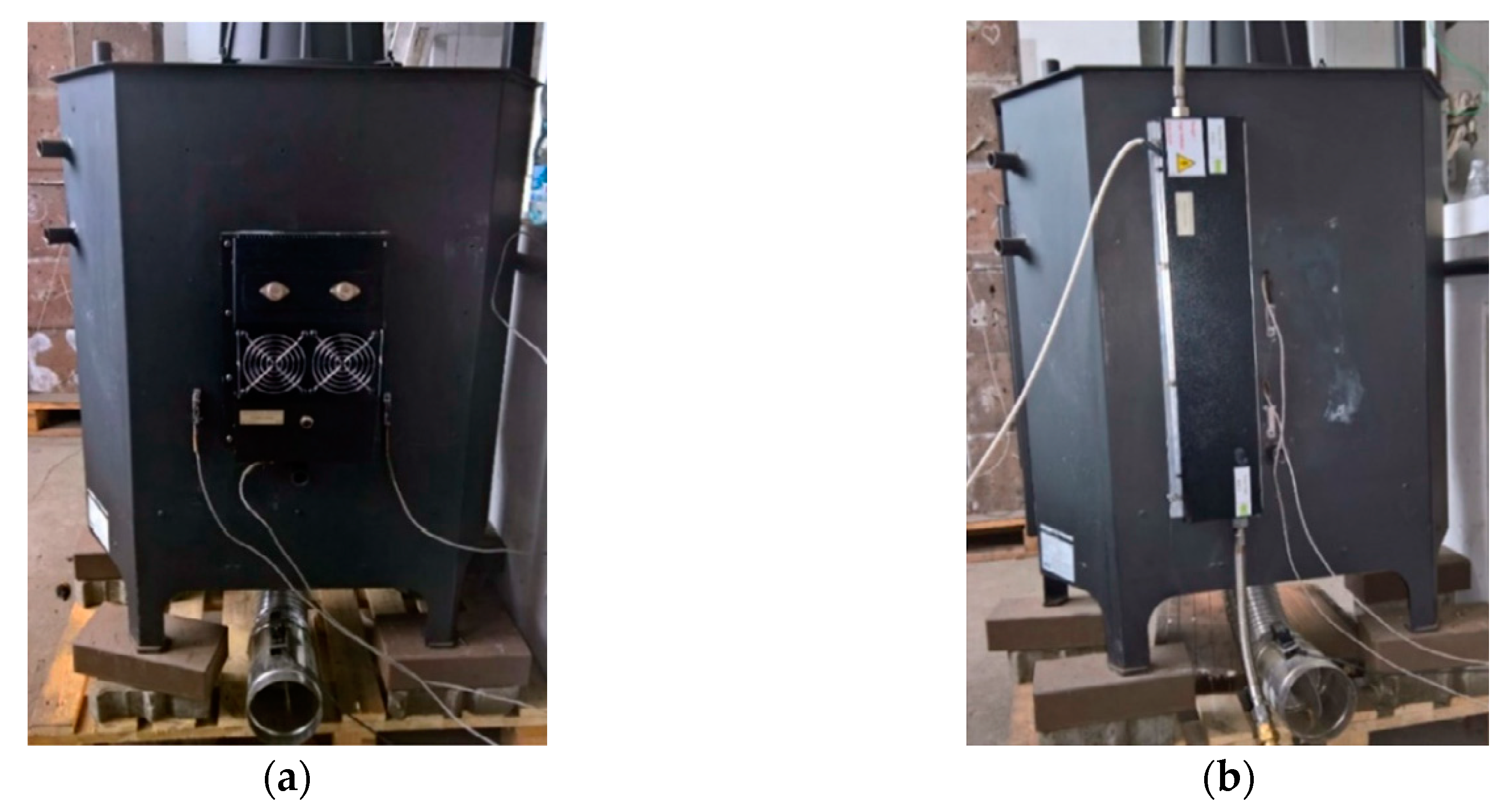
A 45 We thermoelectric generator (TEG1) designed for mounting on a flat hot which consists of six TE modules, an aluminum plate used for collecting heat and an air fan cooling system (nominal hot side temperature 350 °C);
A 100 We thermoelectric generator (TEG2) designed for mounting on a flat hot surface which consists of eight TE modules, an aluminum plate used for collecting heat and a liquid cooling block (nominal hot side temperature 270 °C).
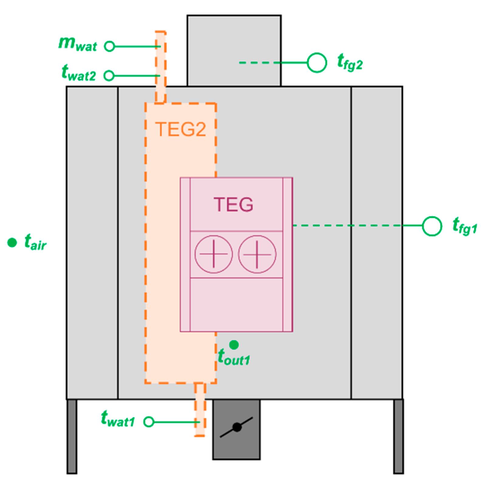
A measurement, control and visualization system based on the WAGO PFC200 controller and equipped with temperature sensors located inside the furnace, inside the flue gas channel, on the rear wall, on the air inlet to the TEG1 and the water inlet and outlet to the TEG2. There were two types of temperature sensors: thermocouple sensors (measurement range 0–1150 °C, accuracy ± 2.5 °C or ± 0.75%) and resistance sensors (measurement ranges 0–250 °C and 0–400 °C, accuracy ± (0.3 + 0.005∙t)). The regulation of the airstream was realized using a throttle. The monitoring and process data acquisition system was developed in the WAGO e!Cockpit software.
The original construction of the tested stove was modified following guidelines developed based on the results of previously conducted studies. Among other modifications, an internal accumulation layer was removed from the furnace and an electronically controlled air throttle was installed. The individual control algorithm was developed to provide an efficient operation from the standpoint of heat and power generation.
The tested thermoelectric generators were placed on the rear wall of the stove (the exact location was determined using infrared thermography measurements). To provide good thermal contact between the stove’s rear wall and the hot sides of the thermoelectric generators, a thermal heat-conducting paste, characterized by thermal conductivity 2.8 W/(mK), was used. The average rear wall temperature during the main phase of the wood combustion process was generally close to 400 °C. On the other hand, the minimum value observed in the upper part of the rear wall was ca. 230 °C and the maximum temperature observed in the bottom part of the rear wall exceeded 500 °C [
25]. The view of the stove with mounted thermoelectric generators is shown in
Figure 1.
The general scheme of the first experimental rig is shown in
Figure 2.
2.2. Experimental Rig 2: A Straw-Fired Batch Boiler with a Steam-Condensate Circuit Operating According to the Modified Rankine Cycle
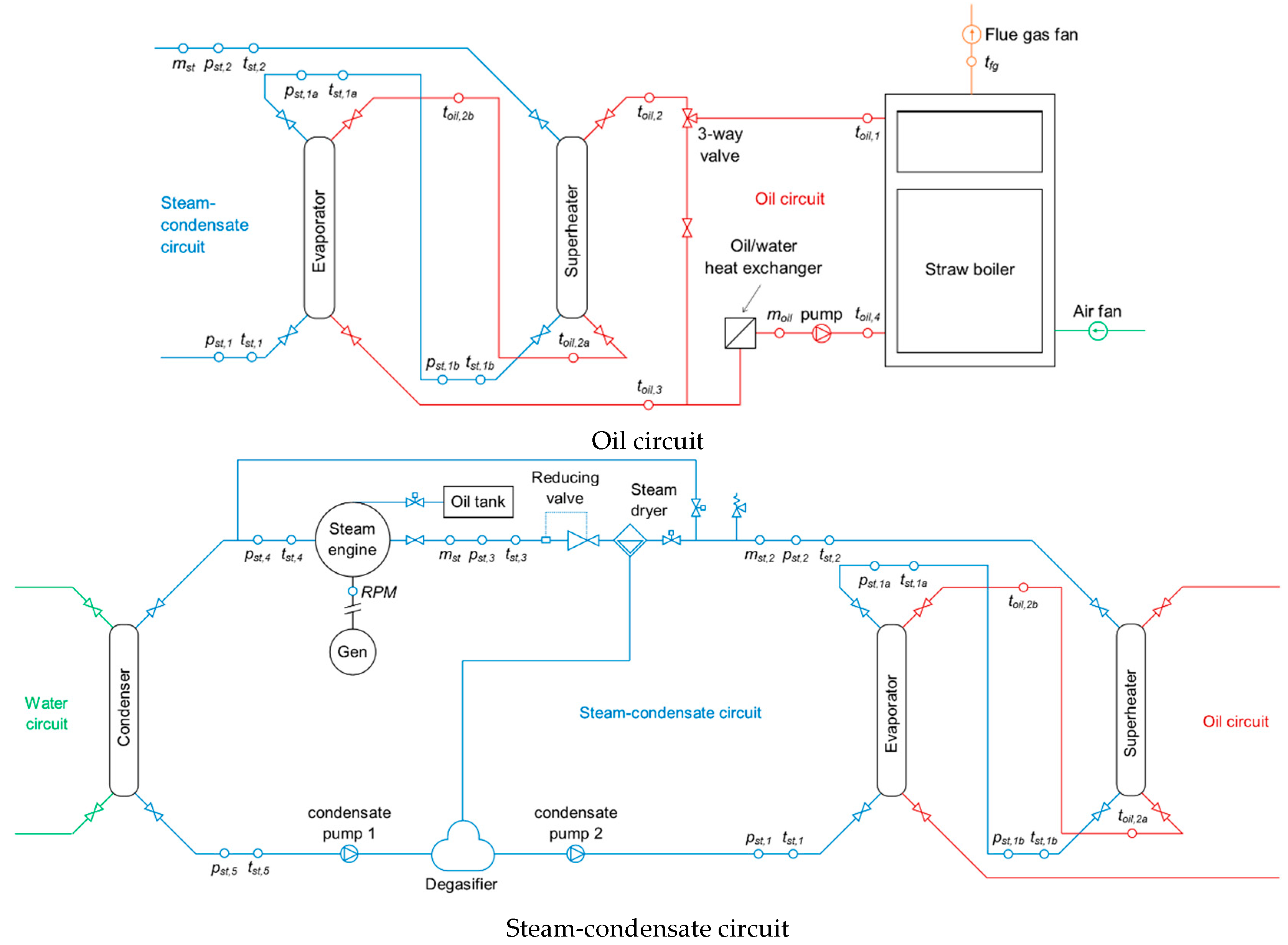
The configuration of the experimental rig number 2 includes three main parts: the oil circuit; steam/condensate circuit; and cooling water circuit and measuring, controlling and visualizing system:
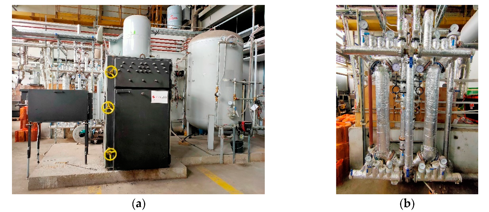
In the oil circuit, oil was heated up in a 100 kW
t straw-fired batch boiler. The boiler had an oil jacket (replacing water jacket) and a dedicated, manual fuel feeder providing a continuous fuel combustion process (see
Figure 3).
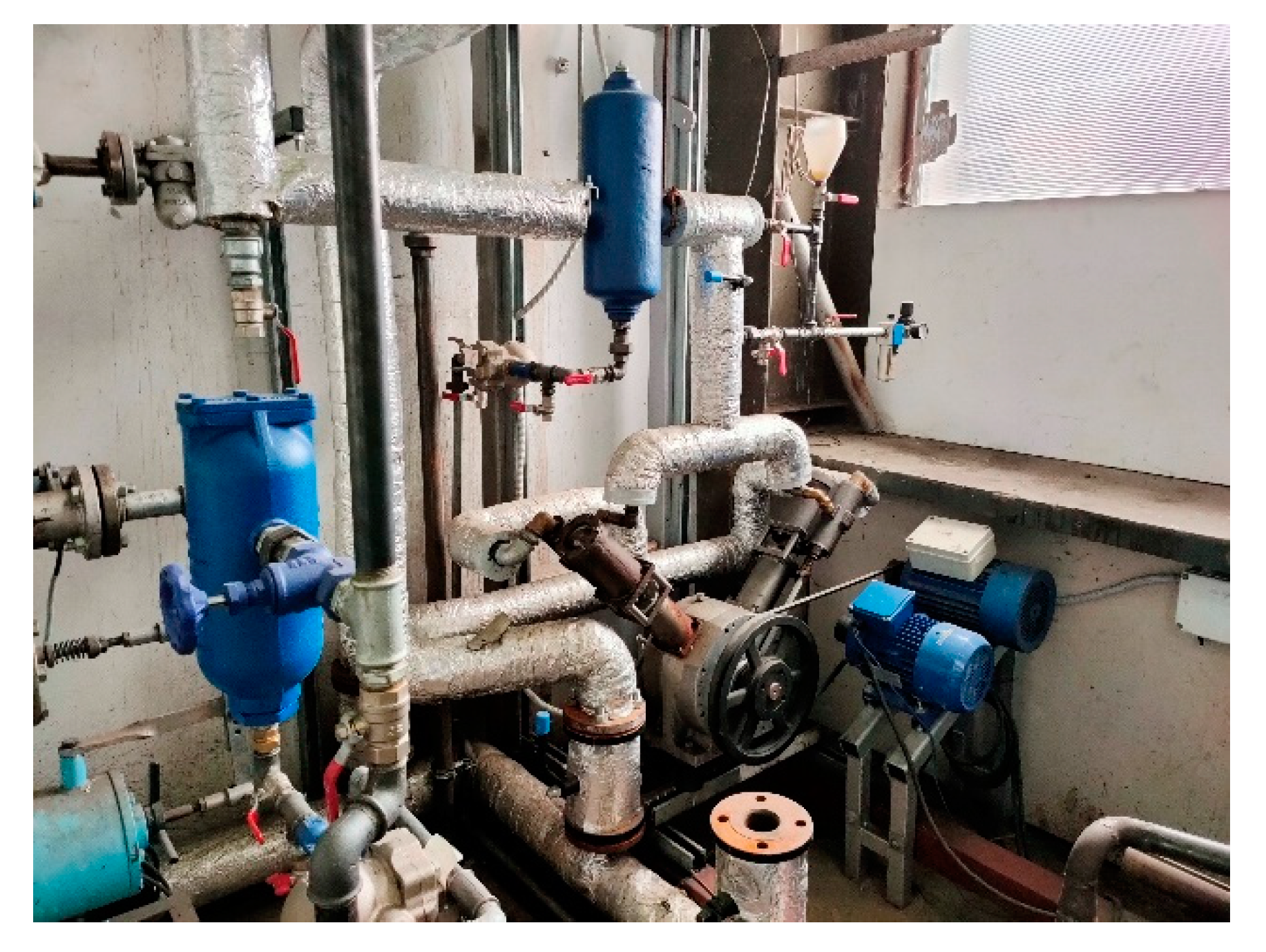
Thermal oil heated up in the boiler was transferred via pipeline to two shell and tube heat exchangers operated respectively as an evaporator and superheater. Generated steam was then superheated and conditioned. After that process, the steam got to the 20-horsepower, 2-cylinder, double-acting steam engine. Partially expanded steam was condensed in another shell and tube heat exchanger (condenser). Water was then pumped to the degasser, and finally to the evaporator. The steam engine (see
Figure 4) was connected to a power generator. The power was consumed by an electric load equipped with 20 bulbs with a total power of 2 kW
e.
The operation of the developed installation was controlled by a dedicated automation system with a WAGO PFC200 PLC controller. Among all controlled parameters were inlet air and flue gas stream; and oil, condensate and cooling water flow. Moreover, several measurements were taken, including temperature, pressure and flow of the flue gas, oil, steam, condensate and cooling water and current and voltage generated in the power generator. The following types of sensors were used: thermocouple temperature sensors (measurement range 0–1150 °C, accuracy ± 2.5 °C or ± 0.75%), resistance temperature sensors (measurement range 0–250 °C, accuracy ± (0.3 + 0.005∙t)), pressure transducers (measurement range 0–10 bar and 0–16 bar, accuracy ± 0.5%), oil flowmeter (measurement range 0–45 m3/h, accuracy ± 0.5%), steam flowmeter (measurement range 0–200 kg/h, accuracy ± 0.5%), water flowmeters (measurement range 0–10 m3/h, accuracy ± 3%), voltage transducer (measurement range 0–400 V, accuracy ± 0.5 V) and current transducer (measurement range 0–15 A, accuracy ± 0.2 A). All controlled and measured parameters were available via CoDeSys software using specially developed visualization.
The proposed configuration of the micro-cogeneration system includes many novel solutions, including, e.g., the oil jacket and fuel feeder (typically not used in batch-boilers), and shell and tube heat exchangers operating as an evaporator and superheater (instead of the classic steam generator) and a steam engine (replacing typically used steam turbines). The simplified scheme of the oil and steam-condensate circuits of the developed system is shown in
Figure 5.
3. Results
Among the many measurement series conducted, only one set of results was selected and presented in this paper.
3.1. Results Obtained with the Experimental Rig 1
3.1.1. The Temperature of the Stove’s Rear Wall
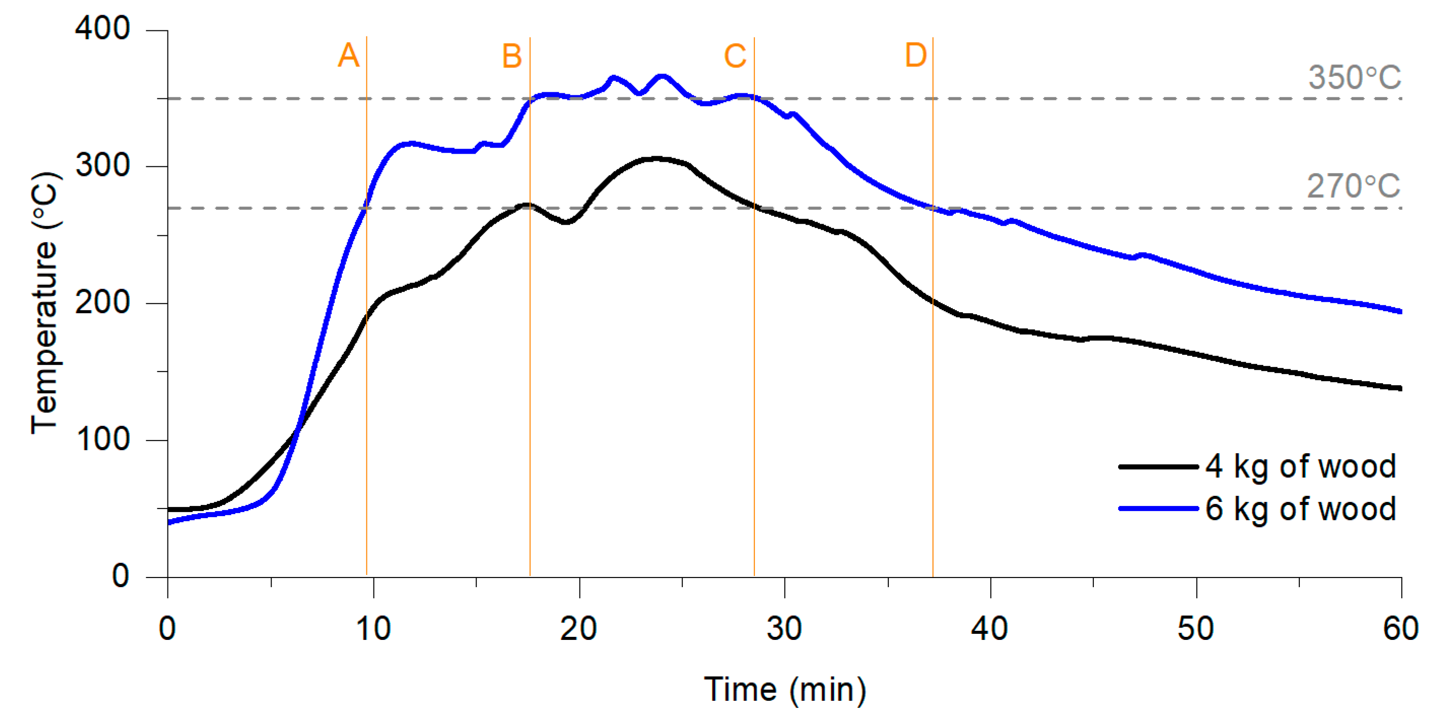
Hot surface temperature is one of the main parameters affecting the thermoelectric generators’ operation (it is directly connected with the heat transferred from the furnace area to the hot side of thermoelectric generators). The stove’s rear wall temperature varied in time and was connected, e.g., with the amount of wood input, the way of fuel combustion (single or continuous process) and control of the stove’s operation. During this study, two fuel inputs were tested: 4 and 6 kg. The typical variations in the rear wall’s temperature are shown in
Figure 6.
During the analyzed measurement series, the maximum observed rear wall temperatures were respectively 305 °C (obtained in minute 24, when 4 kg of wood was burned) and 367 °C (obtained in minute 25, when 6 kg of wood was burned). On the other hand, the average rear wall temperature was significantly lower. Taking into account hot side temperature recommended for TEG1 (350 °C), it was achieved only in case of combustion 6 kg of wood between 18 and 28 min (lines B–C in
Figure 6). On the other hand, the temperature level corresponding to the TEG2 requirements (270 °C) was observed between 18 and 28 min during the combustion of 4 kg wood (lines B–C) and between 9 and 37 min during combustion of 6 kg wood (lines A–D). To extend the time, when the rear wall temperature is equal to power thermoelectric generators, a continuous combustion process should be provided.
3.1.2. The Operating Characteristics of the Thermoelectric Generators
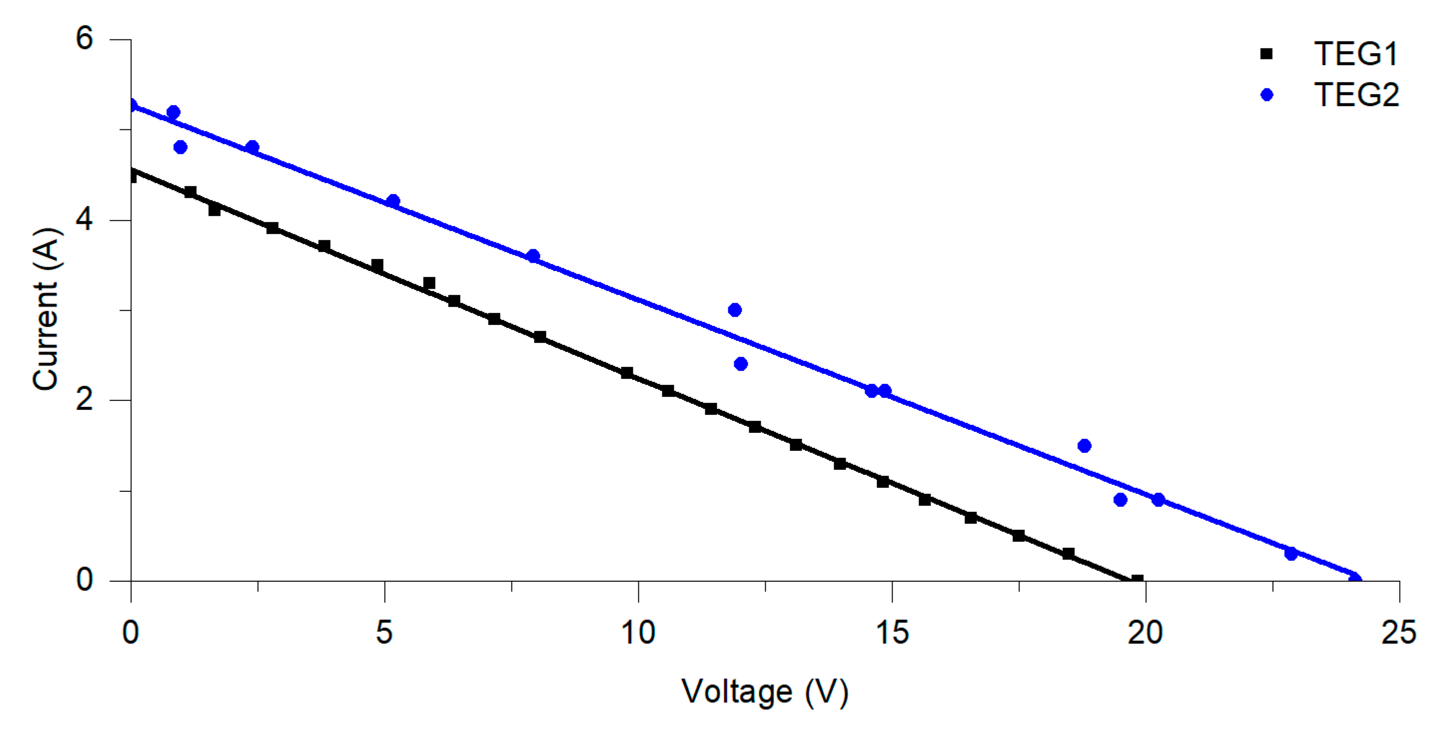
During the presented investigations, cooling medium temperature was ca. 14–15 °C both for water and air cooling TEGs). The temperature of the cold side of TEGs was significantly higher and equal to respectively ca. 140 °C and ca. 71 °C (it was determined based on the calculations of the Seebeck coefficient) [
26,
27]. On the other hand, the hot side temperature was directly related to the amount of wood input and the combustion process phase. Comparing the I–V characteristics of the TEG1 and TEG2, the higher short-circuit current and open-circuit voltage were observed in the case of TEG2 (see
Figure 7).
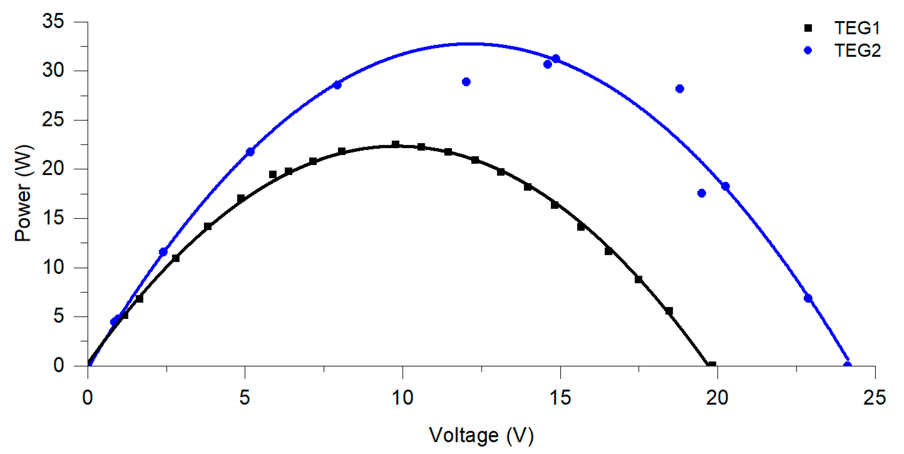
As a result of the current and voltage variations, the power generated by TEGs was significantly lower than their nominal power. The TEG1 operated at 22.5 W at the maximum power point (50% of its nominal power), while the TEG2 operated at 31.2 W (31.2%). Such a situation was caused mainly by the fact that non-uniform surface temperature reduced the heat flux to the hot side of the TEGs and consequently the obtained power (see
Figure 8). In both considered thermoelectric generators the net power was substantially lower because of the controller operation (controller consumes ca. 1.5–6 W
e). Moreover, in the case of TEG2, further reduction in the net power may be observed if power consumed by the water pump is included in the calculations.
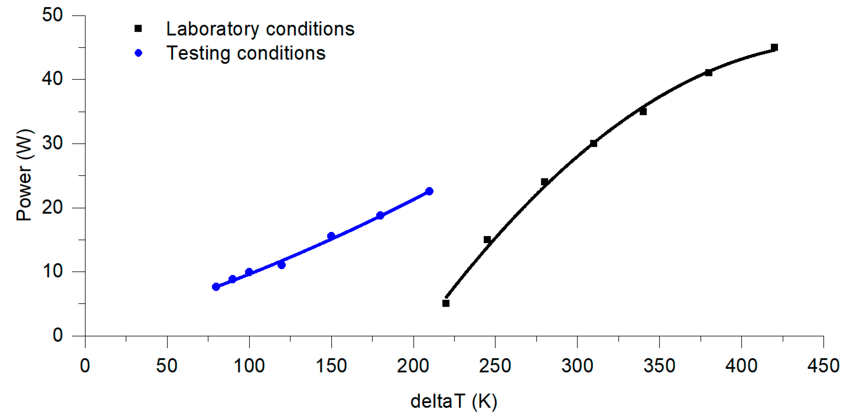
The reduction in the power generated in thermoelectric generators could be also analyzed in the example of a comparison of the TEG1’s operating parameters in testing and laboratory conditions (see
Figure 9). In testing conditions, when the existing stove was used as a heat source, contact between TEG1’s hot side and the stove’s surface was not ideal, and non-homogeneous temperature distribution was occurring on the stove’s rear wall (it was analyzed in [
25]).
3.1.3. Emissions Generated during the Wood-Fired Stove Operation
Analysis of the environmental aspects of the stove operation was carried out for two types of biomass fuel: spruce wood and briquette. Tests were performed for two situations: a stove with an internal accumulation layer (original configuration of the unit) and a stove without an internal accumulation layer (unit modified to use thermoelectric generators). Analyzing the obtained data—the lowest CO emission was obtained for combustion of the wood in the stove without an accumulation layer. The average CO emission was 1916 mg/m
3 in the combustion phase (i.e., in time, when flue gas temperature was higher than 250 °C). This value is much more than Eco-Design requirements, which limit CO emissions for room heaters to 1500 mg/m
3. On the other hand, the average value of CO emission during other series was even higher, achieving a maximum level of 2904 mg/m
3 when the briquette was burning in the stove with an accumulation layer. The average values of CO and other flue gas components (CO
2, O
2, SO
2, NO
x) emission in the combustion phase are shown in
Table 1. By analyzing ecological parameters of the tested stove operation, it may be concluded that removal of the accumulation layer does not impact the CO emissions negatively.
3.1.4. Economical Aspects of the Use of Thermoelectric Generators
During typical operation of the stove, the controller consumes 1.5–6.0 We. Assuming the average daily time of the stove’s operation at a level of 6 h (during the heating season), the controller consumes less than 20 Whe per day. If the water pump is taken into consideration (during operation of TEG2), an additional 40–50 Whe should be added (on the other hand, the water circuit may be an independent system or serve as a part of the hot water system). Thus, it may be assumed that 20 Whe or 70 Whe is required for a self-sufficient operation of the stove. Taking into account the maximum power obtained from the considered thermoelectric generators during tests, it will be possible to generate ca. 112.5 Whe and 156 Whe respectively from TEG1 and TEG2 (electricity generated only in combustion phase). As a result, net power at a level of ca. 92.5 Whe (in the case of TEG1) and ca. 86.0–136.0 Whe (in the case of TEG2) may be stored in batteries and used to power domestic appliances.
Considering only the economic reasons for using the TEG in the analyzed system, it would be unprofitable without external funding. Assuming that the price of the thermoelectric generator is 1000 EUR (in cases of both TEG1 and TEG2), yearly generated electric energy is equal to ca. 27 kWhe (TEG1) and 37.4 kWhe (TEG2), and the value of electrical energy in Poland is equal to 0.20 EUR per kWhe, calculated simply payback time (SPBT) = 185.2 years for TEG1 and 133.7 years for TEG2. This contraindicates the use of the TEGs from a purely economic point of view. On the other hand, the economy of the usage of TEGs is not the only argument. By introducing a power generating system, one becomes independent from the electric grid.
3.2. Results Obtained on the Experimental Rig 2
3.2.1. Oil Temperature during Single and Continuous Combustion Processes
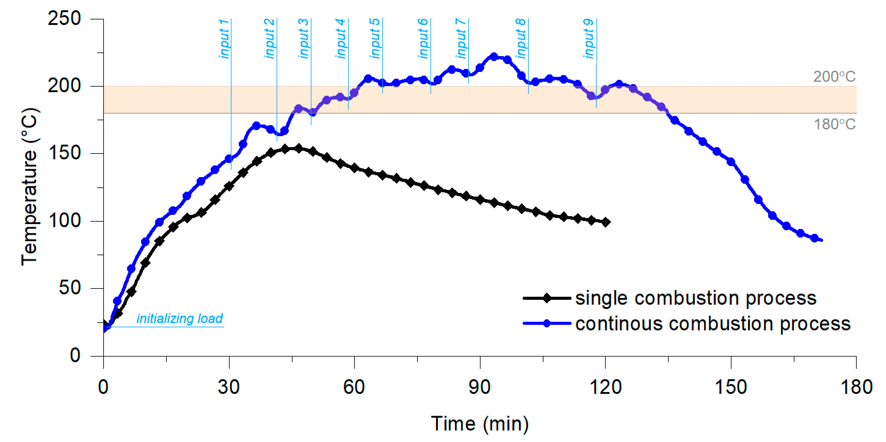
At the beginning of this part of the studies, a single and continuous combustion process was analyzed. During the analyzed single combustion process four rectangular straw bales with total weight ca. 40 kg were burned. In the case of the continuous combustion process, the initial input was also four bales, but the next bales were successively added. Each load matched as “input x” represents one bale weighed ca. 8 kg. In total, ca. 110 kg of straw was burned during the analyzed continuous combustion process. The input of the additional bales was realized by a specially designed and developed fuel feeder. The time shift between two inputs was typically 9–10 min (in cases of fuel inputs 1–7), but for the two last inputs it increased to 14–15 min.
The variations in the oil temperature at the outlet from the boiler during the single and continuous combustion process are shown in
Figure 10. The maximum and average oil temperature in the case of a single combustion process were respectively ca. 154 °C and ca. 115 °C, while in case of continuous combustion process these values were ca. 222 °C and 169 °C. Temperature fluctuations were slight due to the thermal inertia of the boiler. Time when the observed oil temperature was greater than 200 °C was ca. 1 h in case of the analyzed continuous combustion process.
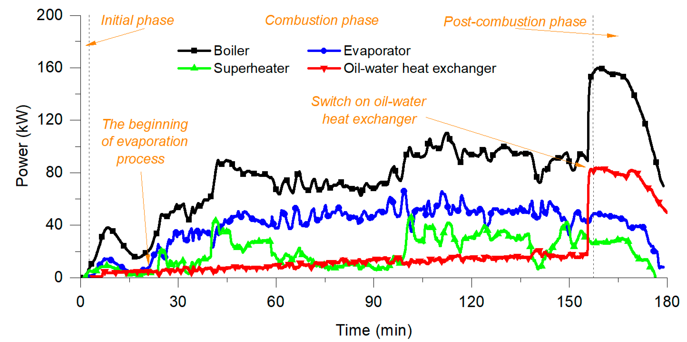
3.2.2. Power Distribution in the Oil Circuit
Hot thermal oil flew from the boiler to the superheater; evaporator; and additionally, the oil–water heat exchanger, respectively. The heat was used to evaporate water and superheating steam, and to heat the water in the water circuit (oil–water heat exchanger was switching on at the end of each measurement series). The average boiler power during the combustion phase was ca. 67 kW
t for the continuous combustion process (comparing to ca. 19 kW
t for single combustion process). The variations in power transferred from oil to condensate, steam and water are shown in
Figure 11.
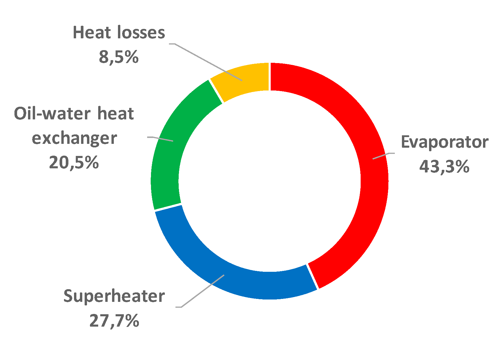
Figure 12 shows the percentage dissipation of the power generated in the boiler in the oil circuit. It may be noted that ca. 71% of heat was transferred to the condensate and steam, while 20.5% was transferred to water (mainly in the post-combustion phase). Ca. 8.5% of the heat was lost.
3.2.3. Temperature Variations in the Steam-Condensate Circuit
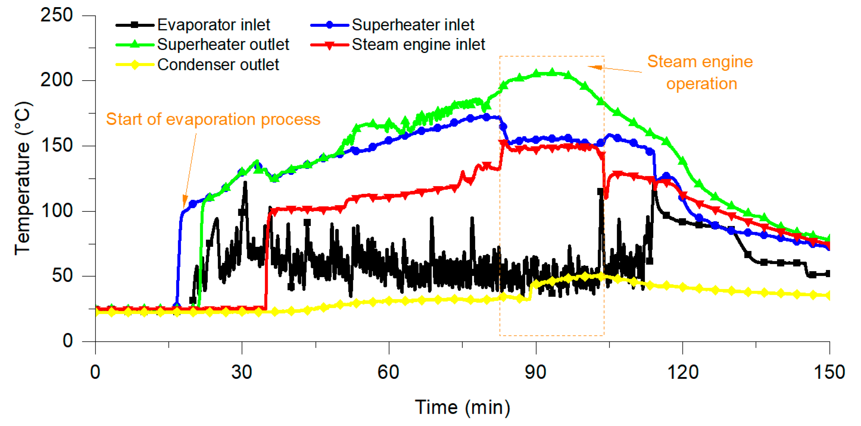
The most important steam parameters from the standpoint of power generation are pressure, temperature and flow. The variations in the steam temperature at the inlet to the evaporator, between the evaporator and superheater; at the outlet from the superheater; at the inlet to the steam engine; and the outlet from condenser are shown in
Figure 13. The condensate (steam) flew in counterflow relative to the thermal oil. The process of evaporation was initialized in minute 16 and the reducing valve was opened in minute 35. The steam engine operated between 83 and 104 min. The fluctuations in the condensate temperature resulted from the fact that two-state control of condensate level was applied. In time, when the steam engine operated, the average temperature at the steam engine inlet was 155 °C, while the average steam temperature at the superheater outlet was 195 °C.
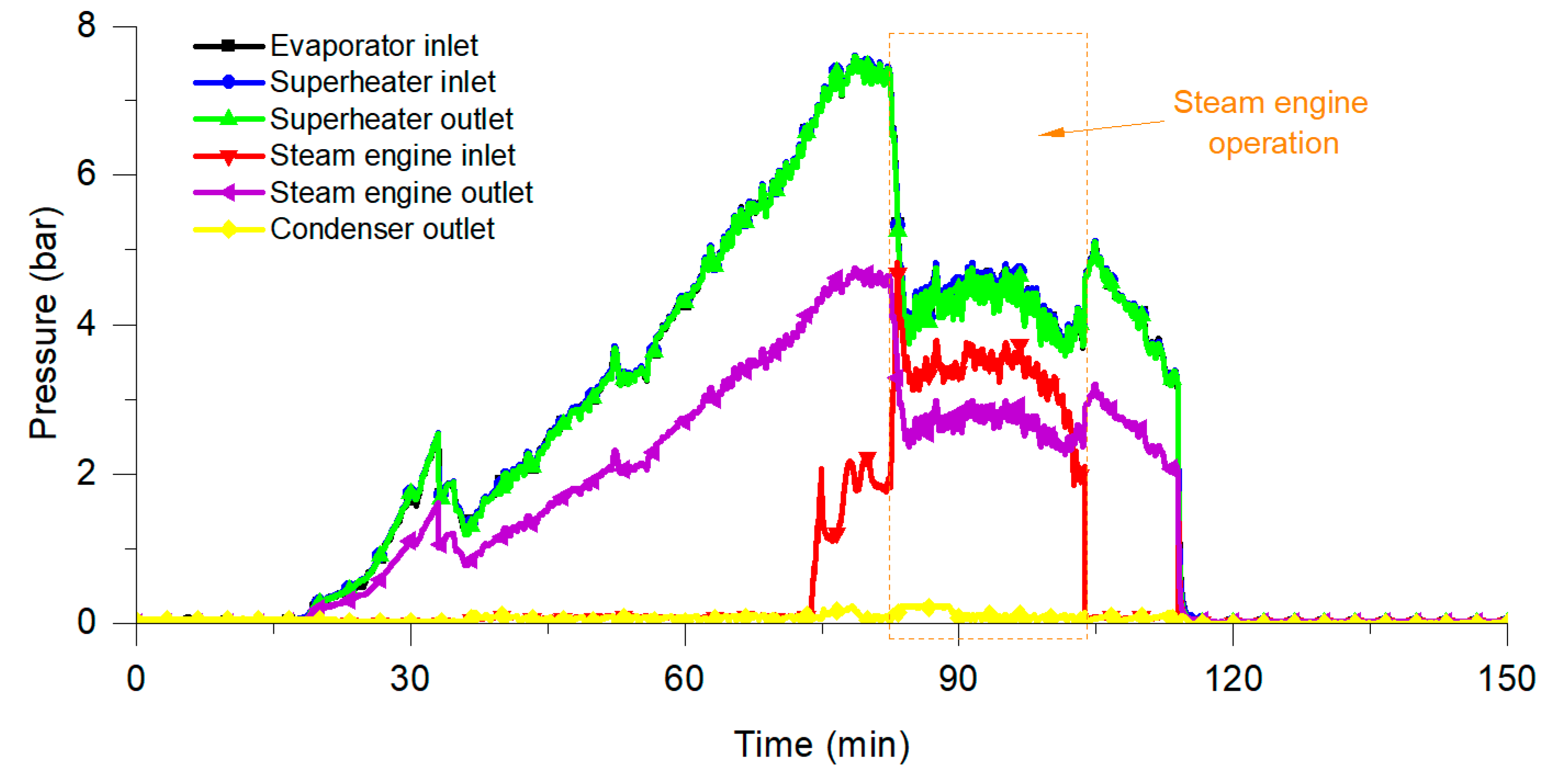
3.2.4. Pressure Variations in the Steam-Condensate Circuit
In the initial part of the evaporating process, steam pressure was rising from 0 to 7.5 bar (maximum value was reached in minute 73). When the steam engine was switched on, steam pressure dropped to 3.5 bar at the outlet from the superheater and 3.0 bar at the inlet to the steam engine. Between 73 and 104 min, when the steam engine was working, the average steam pressure at the inlet to the engine was 3.5 bar and the difference between steam pressure at the outlet from superheater and at the inlet to the steam engine was ca. 1 bar. This reduction in steam pressure was caused by a partial expansion of steam in the steam bus (including pipes, reducing valve and other steam equipment). The variations in steam pressure and flow are shown in
Figure 14.
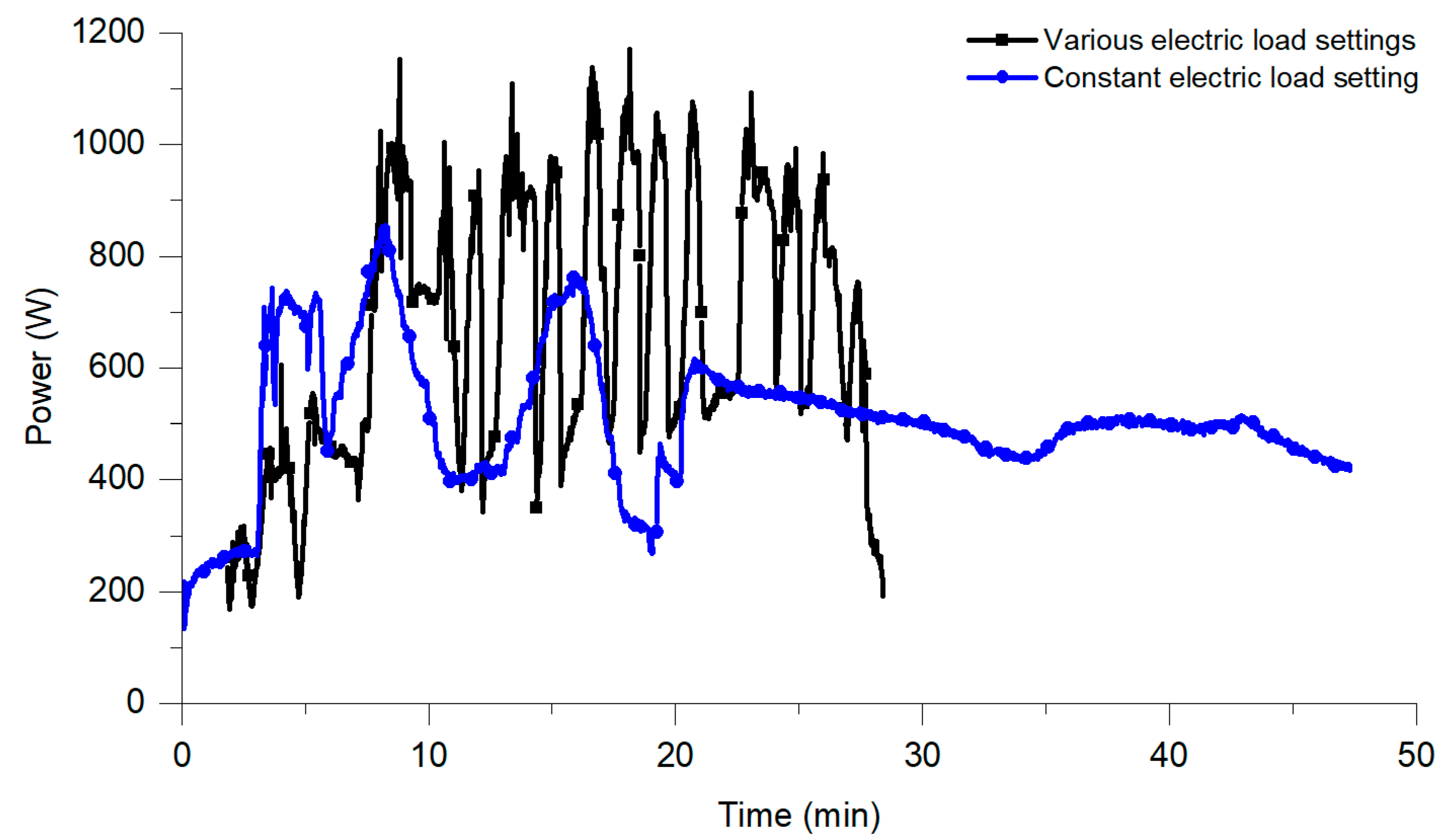
3.2.5. Power Generation Depending on the Operation of Electric Load
The power generated in the power generator resulted from the actual steam pressure and flow and from the settings of electric load. Steam parameters affected the engine’s rotation speed and consequently the generated power.
Figure 15 shows the variations in generated power when constant and various electric load settings were applied. The maximum power level of ca. 825 W
e was observed when a constant electric load was set, while ca. 1145 W
e was obtained when the various electric load was used (this value does not include power required for fans, pumps and other electric components’ operation, which was ca. 5 kW
e). Thus, it may be concluded that the use of the maximum power point tracker (MPPT) should be an essential part of the system.
3.2.6. Environmental and Economic Aspects of the Introduction of the Micro-Cogeneration System with a Straw-Fired Batch Boiler
The actual version of the prototypical micro-cogeneration system is not optimized yet. By introducing all improvements and increasing hot oil temperature, it will be possible to reach ca. 10 kW
e, as estimated through the preliminary simulation with TRNSYS software [
28,
29]. In the first version of TRNSYS model, the following components were included:
Type 5 (heat exchanger—a component used to simulate the amount of heat transferred from the boiler to the oil circuit),
Type 637 (steam generator—a component used to simulate the operation of the evaporator and superheater),
Type 598 (condenser),
Type 4 (water tank),
Type 3 and
Type 618 (pumps),
Type 31 (pipeline),
Type 647 (diverting valve),
Type 2 (controllers) and other components. The above-mentioned components have been parameterized using measurement data. On the other hand, a dedicated component was created to simulate the operation of the steam engine. The actual version of the TRNSYS model does not simulate the process of thermal utilization of straw in the batch boiler. Instead, the heat source was parameterized based on measurement data (i.e., temperature and oil flow measured during combustion processes in laboratory conditions).
Assuming the electricity generation at the level of ca. 10 kWe, it will be possible to provide self-sufficient operation of the system (energy consumed by pumps, fans and other components is ca. 5 kWe). Additional power (ca. 5 kWe) will be available to power, e.g., domestic appliances and other electric devices.
Taking into account simulation results, the estimated differences in CO
2 emissions during the combustion of coal, gasoline and natural gas compared to straw combustion are presented in
Table 2. The analysis was conducted for five variants of daily work time (8, 12, 16, 20 and 24 h), assuming that the installation works 95% of the time in a year. As it can be observed, straw is characterized by lower CO
2 emission only compared to coal.
Taking into account previously assumed electricity generation at the level of ca. 10 kW
e (only 5 kW
e available for any use), and taking into account an average electricity price of 0.20 EUR/kWh
e, potential electric energy cost savings were calculated (see
Table 3). Calculations were made for five variants of daily work time (8, 12, 16, 20 and 24 h), assuming that the installation works 95% of the time in a year. When analyzing the economic aspects of heat and power generation in the straw-fired micro-cogeneration system, it was assumed that straw was a free and local available fuel (as a residue of agricultural production). Investment costs will depend, among other things on the finally used solutions (materials and components) and production volume. It may be estimated that the payback period will be less than five years.
4. Conclusions
This paper shows two examples of biomass-fired micro-cogeneration systems: a system with a wood-fired stove and market-available thermoelectric generators, and the system operating according to the modified Rankine cycle using a straw-fired batch boiler as the heat source. These two cogeneration technologies were selected, taking into account construction parameters of the considered stove and boiler, and available temperature and power, which may be obtained from the analyzed devices. The approach presented is original—the analyzed devices are not widely studied in the context of combined heat and power generation and include several novelties compared to other available solutions.
Thermoelectric generators are promising electricity generating units, which may cooperate with home heating devices (stoves, boilers, etc.). However, although it seems to be a relatively simple task, problems with proper selection and complicated use of thermoelectric generators do arise. As was shown, the power generated by tested TEGs was significantly lower than their nominal power. The TEG1 operated at 22.5 W at the maximum power point (50% of its nominal power), while the TEG2 operated at 31.2 W (31.2%). Such a situation was caused mainly by the fact that non-uniform surface temperature reduced the heat flux to the hot side of the TEGs and consequently the obtained power. Simply calculated payback time (185.2 years for TEG1 and 133.7 years for TEG2) contraindicates the use of the TEGs from a purely economic point of view. On the other hand, the economy of the usage of TEGs is not the only argument. By analyzing the environmental impact of the stove used, the lowest CO emission was obtained for combustion of the wood in the stove without an accumulation layer. The average CO emission was 1916 mg/m3 in the combustion phase. This value was higher than Eco-Design requirements, which limit CO emission for room heaters to 1500 mg/m3.
The operational parameters of the developed micro-cogeneration system with a wood-fired stove and thermoelectric generator may be improved. In general, there are two possible approaches:
Modification of the heating device’s structure to provide a flat area, improvements in the air distribution system to provide high temperature inside the furnace and sufficient heat flux, etc.;
Design and development of a dedicated TEGs structure characterized both by proper operation parameters and acceptable investing costs.
Additionally, the electrical efficiency of the second described system—a prototypical micro-cogeneration installation with a biomass-fired boiler and modified Rankine xycle—was not satisfying. When analyzing the percentage dissipation of the power generated in the boiler in the oil circuit, it was observed that ca. 71% of heat was transferred to the condensate and steam, while 20.5% was transferred to water (mainly in the post-combustion phase). Ca. 8.5% of the heat was lost. As was stated, the most important steam parameters from the standpoint of power generation were pressure, temperature and flow. In time, when the steam engine operated, the average steam temperature at the superheater outlet was 195 °C, while the average temperature at the steam engine inlet was 155 °C. The maximum steam pressure (7.5 bar) was observed during the initial part of the evaporating process. When the steam engine was switched on, steam pressure dropped to 3.5 bar at the outlet from the superheater and 3.0 bar at the inlet to the steam engine. As a result, the maximum power was only ca. 825 We (when a constant electric load was set) or ca. 1145 We (when the various electric load was used).
To achieve a higher level of power generation, some modifications should be introduced, including:
Extension of the heat exchange surface in the evaporator,
Reduction of the length and dimension of pipes in the steam bus,
Replacement of actually used power generator (due to too low installed power),
Fully automation of the system operation.
Introducing the above-mentioned improvements should allow one to reach electricity generation at a level of ca. 10 kWe (this value was estimated based on a preliminary dynamic simulation using TRNSYS software).


