Article

Research on Groove Method to Suppress Stall in Pump Turbine

School of Mechanical Engineering, Shanghai Jiao Tong University, Minhang, Shanghai 200240, China
*
Author to whom correspondence should be addressed.
Energies 2020, 13(15), 3822; https://doi.org/10.3390/en13153822
Submission received: 1 June 2020 / Revised: 13 July 2020 / Accepted: 21 July 2020 / Published: 25 July 2020
(This article belongs to the Special Issue Underground Pumped Storage Plants)

Abstract

:
The pump turbine is prone to stall when running at part-load operation. Stalls would cause a hump-like head characteristic curve, low-frequency high-amplitude pressure pulsation, and surge or resonance in the system. There is a lack of efficient methods for pump turbine stall suppression. The traditional blade hydrodynamic optimization method has limited effect and would influence the other characteristics. As the essence of stall is flow separation, forming a severe backflow vortex, a “Groove Method” is put forward and employed to suppress stall in a pump turbine with the full consideration of the mechanical structure, flow field, and pressure field. Both experiments and calculations are carried out to test the effectiveness of this new method. Furthermore, its deep mechanisms are revealed. This method can weaken the head hump to a certain extent and reduce the pressure pulse amplitude induced by stall. Meanwhile, the performance at the design operating point is not disturbed much.

1. Preface

The stall, as a flow instability phenomenon, is common in pump turbines, centrifugal pumps, axial pumps, and so on. Generally, at part-load operations with a small flow rate, the blade inflow angle changes, inducing flow separation, vortex, and backflow on the blade suction side, which then blocks the flow path [1,2,3]. This phenomenon is called stall, and it usually induces a local head hump and high-amplitude pressure pulsation with low frequency, both of which would trigger a surge and wicked resonance in the system [4,5]. Researchers have invested a lot of energy in researching this problem, mainly focusing on the formation mechanism and its impact. For the first time, Emmons et al. [6] clearly explained stall propagation. Murai [7] observed and studied the stall phenomenon in the axial flow pump. It was concluded that when the flow coefficient decreases to a certain value, rotational stall occurs. Lenneman and Howard [8] studied the flow pattern in the blade when the rotating stall occurred and gave the ratio between the rotating speed of the stall zone and the impeller speed. It was found that the lower the impeller speed and the larger the flow coefficient, the smaller the ratio. Yoshida et al. [9] observed that the vaneless diversion shell has four rotating stall zones in the range of large flow coefficients, and its rotating velocity is measured to be about 20% of the impeller speed. Krause et al. [10] used the PIV method (Particle image velocimetry) to analyze the flow field of a rotating stall under different operating conditions of a centrifugal pump. Ullum et al. [11] measured the pressure and velocity data in a rotating stall flow field in a centrifugal pump for frequency domain analysis. Ran et al. [12] improved the pulsation characteristics of the pump-turbine and the positive slope of the lift curve by impeller optimization, and achieved certain results. Moghaddam et al. [13] used a decoupled sliding-mode neural network variable-bound control system to drive the system back to the optimal operating point to quickly get out of the stall state, but not to suppress the stall mechanically. Halawa et al. [14] injected air flow into the casing opening near the vaneless zone of the compressor to suppress stall and achieve certain effects. Li et al. [15] studied the rotational stall of a jet pump and considered that the rotational stall is closely related to the formation of a hump, and the gap size between the rotor and stator has a great influence on the stall degree. Wang et al. [16] used the Fractal Dimension in Reconstructed Phase Space Method to analyze the rotational stall in a centrifugal compressor and concluded that this method is advantageous for stall resolution. Zhang et al. [17] analyzed the pressure pulsation and stall characteristics of a centrifugal pump with a slope volute when a rotational stall occurred. Halawa et al. [18] studied the difference in compressor stall between a vaneless and vaned diffuser and found that the vaneless diffuser would cause the impeller to have the same impact from the stall unit, while the vaned diffuser did not. Similarly, Heng et al. [19] also analyzed the rotational stall of a centrifugal pump equipped with a vaneless diffuser.
The stall phenomenon is essentially a backflow formed by the separation of the boundary layer. The traditional suppression method is to optimize the blade hydrodynamic shape, but its effect is limited. It is necessary to propose new theories and methods to solve the problem. In other fields, there are more methods to suppress boundary layer separation. According to the mechanism, those methods can be divided into active suppressions, such as jets, and passive suppression such as the use of solid vortex generators including pits and slots. The use of vortex jets and synthetic jets in diffusers can effectively suppress flow separation [20,21]. The use of vortex jets and synthetic jets in compressors can effectively suppress flow separation in flow passages [14]. A hydrofoil C groove can suppress vortex formation and cavitation [22,23]. At present, no researchers have tried to apply these methods to solve stall in blade-type hydrodynamic machinery like pump turbines. This is because the working fluid of the compressor is air, which is much different from water in density, viscosity, and compressibility. Those differences affect the method effectiveness and may cause structural strength issues. Meanwhile, the methods applied in a hydrofoil are not sufficient and always difficult to directly apply to blade-type hydraulic machinery, as it may possess a three-dimensional twisted blade shape, complex cascades, strong interference from upstream and downstream, numerous working conditions, and complicated design requirements. Although there are many difficulties, the above methods are still very promising approaches to solve stall in blade-style hydrodynamic machinery.
This article explored for the first time the above methods on suppressing stall in a pump turbine. The boundary layer separation groove passive suppression method (hereinafter referred to as the “Groove Method”) was applied to form a jet, increasing the momentum of the boundary layer and restraining stall formation. Both experiments and calculations verified that the “Groove Method” was able to suppress stall, weaken the head hump, and reduce the pressure pulse intensity caused by stall to a certain extent. Besides, the “Groove Method” had little negative influence on the design operating point. The rationality and feasibility of this method were initially proved.

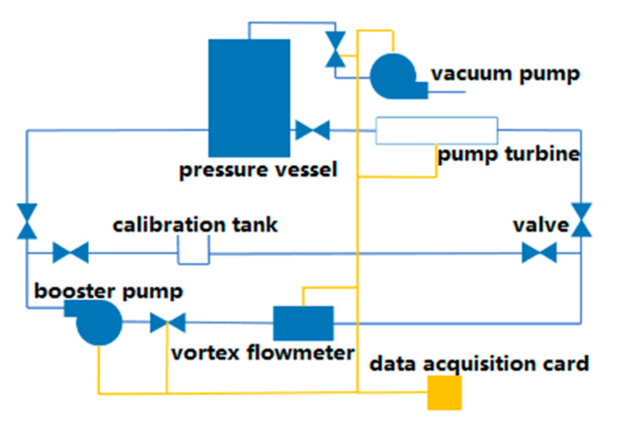
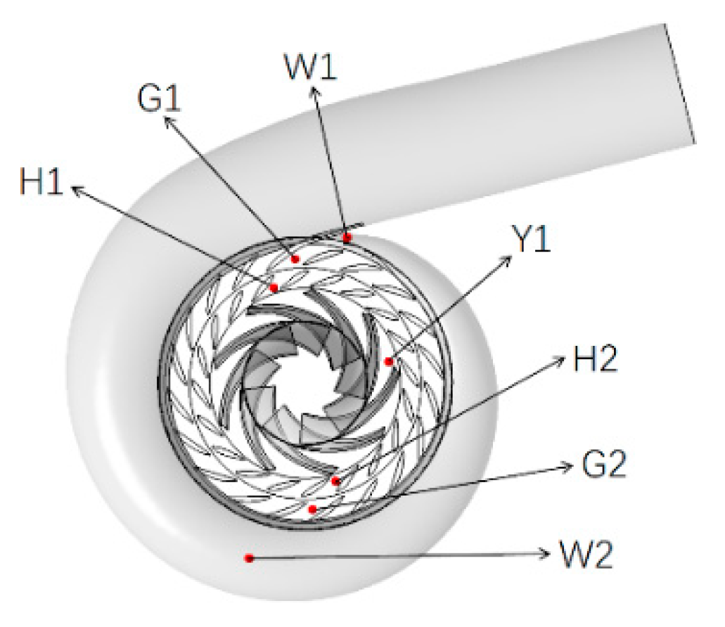
2. Model Machine and Experiment Introduction

The experiment is conducted on a pump turbine model shown in Figure 1, and its main geometric parameters in pump mode are listed in Table 1, where Din, Dout, Zr, Zg, and Zs mean inlet diameter, outlet diameter, the number of impeller blades, the number of guide vanes, and the number of stay vanes in sequence. Figure 2 demonstrates the hydraulic mechanical test bench, where impeller speed and torque are collected by a YB1-type torque meter, the inlet and outlet pressure of the pump turbine are collected by a TS110-type pressure sensor, and the system flow rate is monitored by a turbine flowmeter. All above signals are received by an NI USB-6003 acquisition card and processed by software LABVIEW 2018. The comprehensive efficiency error of the test bench is less than 0.7%.

3. Calculation Introduction

According to actual parameters of the test pump turbine, a 3D model was built, as shown in Figure 1a. ANSYS ICEM 19.0 was used to divide the unstructured grid, and mesh refinement was adopted near the blade surface and volute tongue for “Y+ < 20,” which met the calculation requirements. The grid independence test was to increase the grid number and observe the change in a certain key calculated value. When the change in the calculated value after each grid number increase is not greater than a certain percentage of the previous calculated value, it can be considered that the number of grids no longer affects the results. This percentage varies from 0.23% to 5% in different literatures. Here, 3% of the head value was set as the judgment standard to take into account both the calculation accuracy and the calculation cost. The grid independence was carried out under the design operating point. The final grid scheme was determined, as shown in Figure 3, containing 12 million grid cells and 2.07 million nodes.
In order to capture the pressure pulsation in the pump turbine, monitoring points were set as shown in Figure 4. The monitoring point Y1 was located at the outlet center of the impeller channel. H1 was added at the inlet of the guide vane channel. H2 and H1 were symmetrical about the pump axis. The arrangement of G1 and G2 in the stay vane was consistent with H1 and H2. W1 in the volute was arranged near the tongue, and the monitoring points W2 and W1 were set symmetrical.

3.1. Calculation Settings

Fluid calculation was carried out by ANSYS CFX 19.0. A smooth and non-slip wall surface, mass flow inlet, and static pressure outlet were adopted in the calculation. The SST k-ω model with better near-wall treatment was chosen for flow separation simulation. The advection scheme and turbulence scheme were both set to High Resolution, and the transient scheme were set to Second Order Backward Euler. The residual RMS (Root-Mean-Square) convergence criterion was set to be 10-4. The timestep in the unsteady calculation was 0.0002541 s for the impeller rotating 2°, and the total time was 1.7 s for the impeller to rotate 37 times. As the calculation is not stable enough in the initial stage, the calculation results of the first 10 rotations of the impeller are eliminated to ensure the accuracy of the calculation results. The remaining reliable data covered the frequency domain of 1–3900 Hz, which satisfied the research need.

3.2. Calculation Feasibility Verification

The key characteristic parameters of the pump turbine model when working at the design point under the pump condition are shown in Table 2, where n is the impeller rotating speed, QN is the design flow rate, HN is the design head, ns is the specific speed, and γ is the guide vane degree. Mass flow rate Qm and pump turbine head H are normalized as qm and h by QN and HN, respectively, with the corresponding expressions shown in Equations (1) and (2):
q m = Q m / Q N
h = H / H N
The feasibility of the calculation was verified by comparing its head results to the experiment, as shown in Figure 5. The results in Figure 5 were from steady calculation, and the results were the initial files for unsteady calculation in the paper. It revealed that the CFD calculation results were the closest to the experimental results near the design point of qm = 1. Though the error was larger when the curve deviated from the design point, it was still within an acceptable range. The hump area calculated by CFX was slightly ahead of the experiment, but the calculation still captured the hump phenomenon caused by the stall well. In summary, the calculation was feasible.

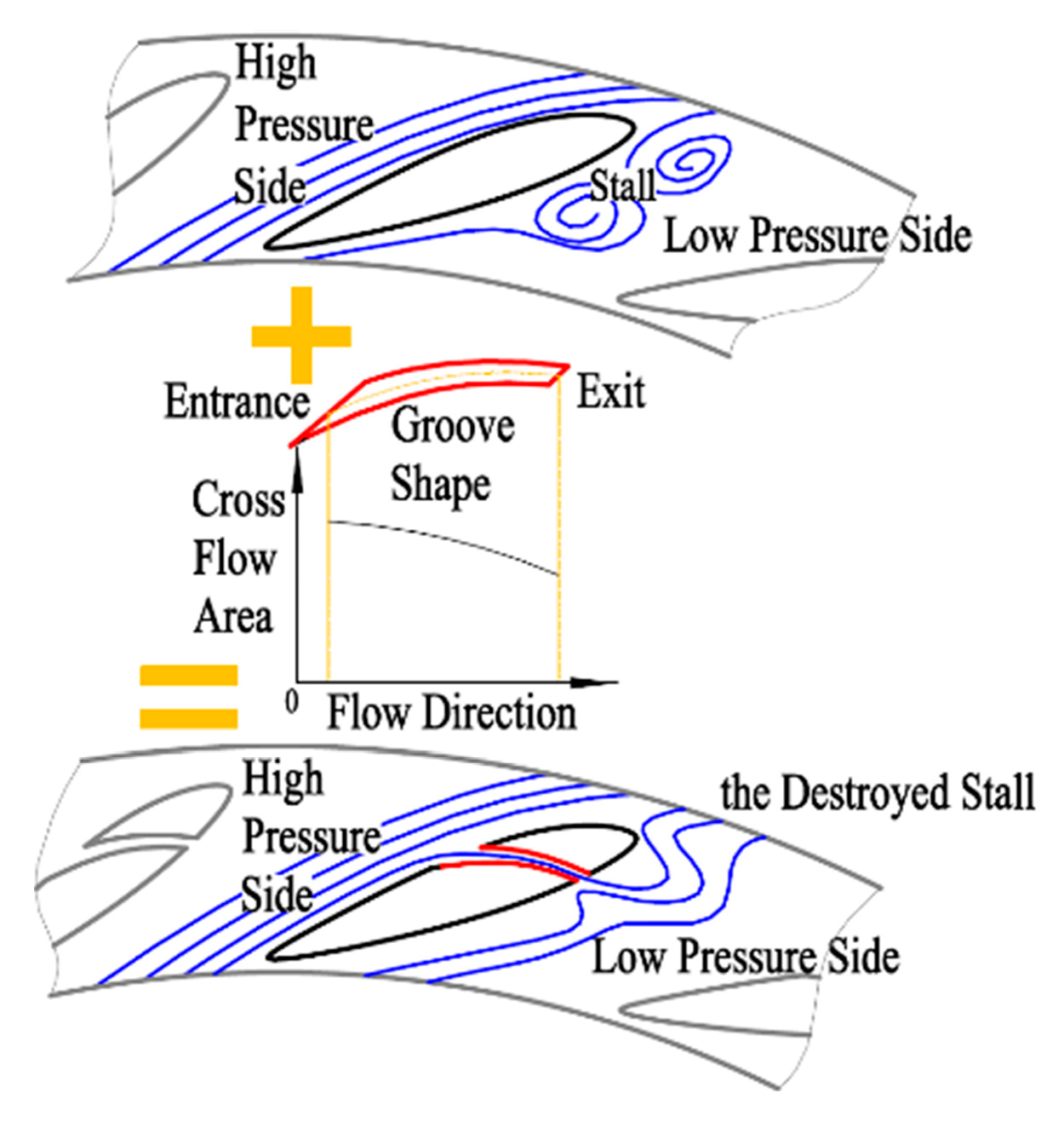
4. Mechanism of Groove Method to Suppress Stall

The fluid flow velocity of the impeller can be decomposed into two components: Relative velocity and implicated velocity. The relative velocity is the flow velocity observed in the impeller dynamic coordinate system, and the implicated velocity is equal to the local linear velocity of the impeller rotation. When a pump turbine enters part-load operation with a small flow rate, the relative speed of the impeller outflow decreases and the implication speed changes little as the impeller rotates with a constant speed. The actual vector speed of impeller outflow both changes in size and direction. The smaller the flow rate, the bigger the angle of attack at the guide vane inlet and the more severe the flow separation; thus, obvious backflow vortexes are formed in channels, which are called the stall [21]. The “Groove Method” proposed in this paper is shown in Figure 6. On the premise of making full use of the characteristics of the flow and pressure field in the pump turbine, grooves are reasonably slotted on guide vanes, and then a non-free submerged jet is formed in channels to enhance the boundary layer momentum. The jet help fluid near the blade overcomes the viscous force and the adverse pressure gradient, and thus, the flow separation on the blade suction side is suppressed; namely, the stall is suppressed.
The groove is constrained by a series of parameters, including the position of the groove inlet and outlet, the shape of the groove, and the changing trend of the cross-sectional area in the groove. The inlet and outlet positions jointly determine the maximum pressure difference loaded upon the groove, and the outlet position directly affects the effect of the jet on increasing the boundary layer momentum. The groove shape is very important to reduce the energy loss when fluid flows through the groove. Reasonable shape can effectively reduce the hydraulic loss and increase the jet flow. The gradual reduction in the groove cross-sectional area along the jet direction can help the fluid obtain higher speed and enhance the jet effect.
The solid black line in Figure 7 indicates the head curve of the pump turbine model before the “Groove Method” is used, and two obvious hump regions caused by stall can be seen. The other lines represent head curves after different shapes of grooves are applied. Compared to the original external characteristic curve, after scheme 1 is adopted, the hump near qm = 0.7 is shifted to a smaller flow rate and the hump peak–valley difference is reduced. After adopting scheme 2, the peak–valley difference does not decrease, and several new humps arise, making the external characteristic curve more unstable. Different groove schemes have different effects on the pressure gradient distribution and flow velocity distribution in the guide vanes. Reasonable schemes can delay the flow separation in the guide vanes. Unreasonable schemes can lead to early flow separation. The hump is closely related to the flow separation in the guide vane, so different groove schemes have different effects on the hump. The conclusion can be easily drawn that the groove shape significantly affects the final effect of the “Groove Method.”

5. Results and Analysis

Stalls in pump turbines often bring adverse effects like the head hump and low-frequency strong-pressure pulsation, which threatens the safe and stable operation of the pump turbine system. The effectiveness of the “Groove Method” must be analyzed and verified from both aspects. In addition, we hope that the “Groove Method” interferes as little as possible with the pump turbine operating performance at the pump design point. Therefore, the influence of the “Groove Method” on the pump design point should also be included in the analysis and verification.

5.1. Verification of “Groove Method” to Weaken the Head Hump

Whether the “Groove Method” can effectively weaken the “hump” is a key indicator to verify its effectiveness. Here, it is verified by both calculation and experiment. The “Groove Method” here adopts scheme 1 in Figure 7. Due to the inevitable error of calculation, there is a deviation in the hump flow rate between the calculation and experiment, but the two humps are in a corresponding relationship, and the mechanism and formation conditions are consistent. The article uses the calculation to optimize the groove scheme and then conducts experimental verification on the optimal scheme. Therefore, the calculation and test results are both presented below. The head curves of the pump turbine before and after using the “Groove Method” are calculated by ANSYS CFX 19.0, as shown in Figure 8. In the case where the method is not used, when the qm is reduced to around 0.7, the head curve exhibits hump A, and when the qm is further reduced to about 0.5, hump B appears. After the “Groove Method” is used, hump area A is suppressed and shifted to A’ with a smaller flow rate, and the peak-to-valley difference decreases.
To further judge the effectiveness of the method, an experiment was conducted and the head curves were obtained, as shown in Figure 9. The head curves before and after using the “Groove Method” are extremely close in total, indicating that the method does not cause the head curve to deviate significantly from the design value, but there are obvious differences between the two curves in the hump region. Before the “Groove Method” is adopted, the head hump caused by stall occurs around the operating point qm = 0.86, and the positive slope is evident. After the “Groove Method” is adopted, the head hump is weakened and the positive slope curve is eliminated.
The “Groove Method” can increase the momentum of the boundary layer on the guide vane suction surface, avoid or delay the flow separation on the blade surface, effectively suppress stall formation, and avoid the large energy consumption caused by stall. The calculation and experimental results above reveal that using the “Groove Method” to suppress the head hump in the pump turbine is effective.

5.2. Verification of the “Groove Method” to Weaken the Low-Frequency Pressure Pulsation

In addition to causing the head hump, stalls also induce low-frequency pressure pulsations, the frequency of which corresponds to the stall shedding frequency, and its amplitude is often so high that it exceeds all other pressure pulse components to become the first main frequency in the pump turbine. When its frequency is close to a low-order mode of the pump turbine or system, it is easy to cause severe vibration and noise, which seriously threatens the stability and safety of the pump turbine and system. The effect of this method on the pressure pulsation in the pump turbine is verified through calculation from both the design point (corresponding to qm = 1 in Figure 5) and stall point (corresponding to qm = 0.7 in Figure 5).
As shown in Figure 4, the monitoring point Y1 is located at the center of the impeller channel exit, and the pressure pulsation at Y1 under operating points qm = 0.7 and qm = 1 before and after using the “Groove Method” is shown in Figure 10. Figure 10a shows the pressure fluctuation law with time and the magnitude of the overall pulsation, and Figure 10b shows the pressure spectrum. Before the “Groove Method” is used, under the design point qm = 1, the main pressure frequency component in the impeller is 20 fz caused by rotor–stator interaction (fz represents the axial frequency, about 21.7 Hz). Under the stall point qm = 0.7, due to the change in the impeller outflow angle, the RSI (rotor–stator interaction) is intensified so that the amplitude of the 20 fz increases. Most importantly, a low-frequency pressure pulsation of 5.67 fz (about 123 Hz) with extremely high amplitude appears in the impeller under the stall working point, and its intensity exceeds other pulsation components caused by RSI.
Figure 10b reveals that after using the “Groove Method,” the amplitude of the 20 fz component is reduced by about 27% under the design point qm = 1, and the amplitude of the 20 fz component is reduced by about 19% under the stall point qm = 0.7. The main frequency amplitude of 5.67 fz decreases by 25% under the stall point.
Similarly, the influence of the “Groove Method” on pressure pulsation in the pump turbine stators is analyzed. Figure 11 lists the amplitudes of three important pressure pulsation components in the guide vane, the stay vane, and the volute under the working point qm = 1 and qm = 0.7. In Figure 11, “Or” represents “Original guide vane” corresponding to the case where the “Groove Method” is not used, “Mo” represents “Modified guide vane” corresponding to the situation after the “Groove Method” is adopted, f1 represents the one-time impeller blade frequency 9 fz, f2 represents the two-times impeller blade frequency 18 fz, and fs indicates that the low-frequency pulse component caused by stall is equal to 0.3237 fz. It can be seen from Figure 11 that under point qm = 1, the “Groove Method” has less influence on the pressure pulse components f1 and f2 caused by RSI in stators, while under the point qm = 0.7, the components of f1 and f2 in the guide vane are significantly weakened by the “Groove Method,” but the stay vane and volute are less affected. Particularly, the main frequency fs component is significantly restrained by the “Groove Method.” Its amplitudes in the guide vane and the stay vane are reduced by about 9.5% and 25%, respectively. As the volute is far away from the grooves made in the guide vane, it is relatively little affected by the “Groove Method.”
Thus, it can be concluded that the “Groove Method” has some weakening effect on the pressure pulsation in the pump turbine, especially on the low-frequency high-amplitude pressure pulsation component caused by stall in the guide vane and stay vane.

5.3. Impact of “Groove Method” on Flow Field under Stall Point

It has been proven above that the “Groove Method” can effectively suppress the head hump and weaken the low-frequency high-amplitude pressure pulsation caused by stall. However, from the microscopic flow field level, how the “Groove Method” specifically works to restrain stall needs to be further analyzed from the perspective of the flow field through calculation.
In the following, the design point of qm = 1 in Figure 5 and the stall point of qm = 0.7 in Figure 5 are selected to calculate and analyze how the “Groove Method” affects the flow field in the pump turbine.

5.3.1. Analysis of Design Operating Point

Under the design point, the inflow angle on the guide vane is slightly larger than zero, so there is a pressure difference on both sides of the vane to promote flow inside the groove. Figure 12 compares the pressure field and flow field in the guide vane under the design point before and after using the “Groove Method.” As shown in Figure 12a, in the case where the groove is made, the pressure near the pressure side decreases and the pressure near the suction side increases because of the connection effect of the groove.
The flow fields with and without the “Groove Method” are shown in Figure 12b. Before the “Groove Method” is adopted, the flow in the guide vane is orderly, and only some slight flow separation appears at the vane trailing edge. After using the “Groove Method,” the groove jet impacts the flow on the vane suction side, causing the flow to deviate from the original direction a little. Flow separation on the vane tailing edge shows that the flow separation region slightly increases when the grooves are made on vanes.
Thus, the jet flow still exists in the grooves under the design point, but it has just a little influence on the flow field in the guide vane. This is why the method does not affect the performance of the pump turbine much at the design point.

5.3.2. Analysis of the Stall Operating Point

The stall cell exists in a complex spatial form. Firstly, the weakening effect of the “Groove Method” on the stall cell is analyzed in 3D space. The guide vane is evenly sliced along the direction from hub to shroud, as shown in Figure 13, forming 1–9 slices, wherein slice 5 is in the axial center position, and No.1 and No.9 are respectively near the hub and the shroud. By analyzing all slices, the distribution characteristics of the whole 3D stall cell in the guide vane can be understood. Figure 13 uses the turbulence kinetic energy (TKE) cloud to describe the distribution and intensity of the stall cell on each slice. TKE is defined in Equation (3), which shows that TKE is a measure of the turbulence intensity. In expression (3), k represents TKE, ui represents the velocity component of the fluid micelle in the three directions of the Cartesian coordinate system, respectively, ui is equal to u v w in the x y z coordinate axis direction, respectively, the symbol “′” represents the pulsation amount, and “” represents the time average. As the turbulence intensity near the stall cell is significantly higher than the surroundings, it is feasible and convenient to use the TKE cloud to represent the distribution and intensity of stall cells.
k = 1 / 2 ( u i u i ¯ ) = 1 / 2 ( u 2 ¯ + v 2 ¯ + w 2 ¯ )
In Figure 13, the middle column corresponds to the case without the “Groove Method,” and the right side corresponds to the modified guide vane in which the “Groove Method” is used. From slice 1 to 9 for analysis, in the original guide vanes, there is only one slight stall cell on slice 1 near the hub. The strength of the stall cells on slices No. 1–5 increases gradually, and the number of stall cells increases as well. The number of stall cells on slice 3 and slice 5 has been increased to 3 and 4. These stalls are evenly spaced in the circumferential direction, but their intensities are different from each other to some degree. In the axial center section slice 5, the stall cell strength is maximized. Then, on slices 5–9, the stall strength gradually decreases in sequence, while the number of stall cells remains unchanged. More specifically, on slice 9 near the shroud, all the stall cells diffuse to the adjacent flow passages and there is no obvious stall cell on the slice.
The right column in Figure 13 shows the TKE cloud chart in the modified guide vanes. It is easy to see that there is no obvious stall cell from slice 1 to slice 7. The TKE cloud on slice 9 of the original and modified guide vanes is basically the same, and there is a relatively uniform turbulent flow without distinct stall cells in the circumferential direction.
Based on the above analysis, the center of the stall cell is close to the axial center position. All stalls are evenly distributed at an angular difference of 90° in the circumferential direction of the guide vane and have different strengths. The strongest stall cell extends from the hub to the shroud, blocking the normal flow in the channel to a large extent. After using the “Groove Method,” the stall in the guide vane is significantly weakened, and there is no longer a stall cell of the same strength as before. Then, the flow condition in each channel is greatly improved with less hydraulic loss generated during flowing. Therefore, it can be considered that the “Groove Method” effectively suppresses the stall cell in the entire flow field of the guide vane.
For more flow field details, slice 5, where the stall is most violent, is selected for further analysis. Comparison of the pressure field and flow field before and after using the “Groove Method” on slice 5 is shown in Figure 14. Figure 14a,b reveal that the influence law of the “Groove Method” on pressure field in the guide vane is similar to the design point, as shown in Figure 12a. After using the “Groove Method,” the pressure near the outlet of the grooves on the guide vane suction side is significantly increased, and a local low-pressure region occurs near the groove inlet on the pressure side.
Figure 14c,d compare the flow field in the guide vane under the stall point before and after the “Groove Method” is adopted, respectively. In the case without using the method, as shown in Figure 14c, there is a significant stall blocking the channel. The guide vane inflow forms a low-speed boundary layer on vane surface. The larger inflow attack angle under the stall point results in a thicker boundary layer and greater adverse pressure gradient on the vane suction surface. From the vane inlet to outlet, the boundary layer thickness increases in the flow direction. Under the combined action of viscous force and adverse pressure gradient, the boundary layer on the vane suction side separates near the vane outlet to form a stall cell. The stall cell has a large volume, blocking more than half of the channel in the circumferential direction, forcing the fluid into the circumferential adjacent flow channel at an excessively large or small inflow attack angle, resulting in new flow separations in other channels. Rotational stall is formed and propagate under such influence of the stall channel and adjacent channels. The stall vortex dissipates a lot of flow energy and causes large hydraulic loss, which is one of the important reasons for the head hump of the pump turbine under the stall working point.
The effect of the “Groove Method” on the stall cell is shown in Figure 14d. The pressure difference on guide vanes forms a positive pressure gradient in grooves to promote inside flow. Decreasing the flow area in the groove channel helps increase flow velocity in the grooves. A non-free submerged jet with high momentum is formed at the groove outlet. Jets can help the boundary layer increase energy to overcome the obstacles of viscous forces and adverse pressure gradients, and prevent the flow from separating on the vane suction side. In addition, the jet also has the effect of dissipating and destroying stall cells, smoothing the flow in the guide vane. Due to the above-mentioned effects of the “Groove Method,” the stall phenomenon is effectively suppressed, and the apparent stall cells in the guide vanes disappear to some degree.

6. Conclusions

The “Groove Method” was proposed to suppress the stall in blade-type hydraulic machinery, and both simulation and experimental verification were performed on a pump turbine model. This method was realized by making full use of the flow and pressure field in the guide vane, and reasonably slotting the grooves to form a jet. The following conclusions can be drawn from the research:
(1)
The head hump usually appears when the pump turbine works under the stall point. Simulation and experimental results show that the “Groove Method” can effectively weaken the hump and move the hump to a smaller flow rate, which helps the pump turbine expand the smooth flow range and reduce the severity of stall;
(2)
Under the stall point, the low-frequency high-amplitude pressure pulsation caused by stall shedding and interference will often exceed the pressure pulsation caused by RSI in the pump turbine and become the strongest pulse component. When the low frequency is close to the low-order mode of the pump turbine or system, it will cause unsafe accidents such as severe vibration and noise. After verification and analysis, the “Groove Method” can effectively restrain this dangerous pressure pulse component in the pump turbine under the stall point. Its amplitude in the impeller is reduced by about 30%, and the amplitude in the guide vane and stay guide obviously declines as well;
(3)
The “Groove Method” does not cause undesired interference to the design point. It is verified that the external characteristics of the pump turbine under the design point will not be affected by the “Groove Method,” while the pressure pulsation in the pump turbine will be reduced a little by the method;
(4)
The essence of the pump turbine stall is a boundary layer separation phenomenon. The principle of the “Groove Method” to achieve stall suppression is to make full use of the characteristics of the pressure and flow field in the pump turbine to form a high-speed jet before stall cells to increase the momentum of the boundary layer on the guide vane suction surface and help the boundary layer much better overcome the fluid viscous force and adverse pressure gradient. Then, the separation is delayed and the fluid will flow closer to the blade surface;
(5)
The effectiveness of the “Groove Method” has been initially verified in the pump turbine. This method is expected to be researched and applied in more blade-type hydraulic machines, and will play a useful role in solving the stall problem in blade-type hydraulic machines.

Author Contributions

Y.L., Conceptualization, Formal Analysis, Original Draft Preparation; H.R., Methodology, Improvements; D.W., Validation, Supervision. All authors have read and agreed to the published version of the manuscript.

Funding

This work was funded by National Science and Technology Major Project—China (No. GX0200004), and the National Natural Science Foundation of China (51576125).

Conflicts of Interest

The authors declare that they have no conflict of interest.

References

  1. Li, D.Y. Investigation on Flow Mechanism and Transient Characteristics in Hump Region of a Pump-Turbine. Ph.D. Thesis, Harbin Institute of Technology, Harbin, China, 2017. [Google Scholar]
  2. Sun, Y.K. Instability Characteristics and Influencing Factors of Positive Slope on Pump Performance Curves of a Low-Specific-Speed Pump-Turbine. Ph.D. Thesis, Tsinghua University, Beijing, China, 2016. [Google Scholar]
  3. Zhou, P.J. Investigation of Stall Characteristics in Centrifugal Pumps. Ph.D. Thesis, China Agricultural University, Beijing, China, 2015. [Google Scholar]
  4. Brennen, C.E. Hydrodynamics of Pumps; Cambridge University Press: Cambridge, UK, 2011. [Google Scholar]
  5. Dussourd, J.L. An investigation of pulsation in the boiler feed system of a central power station. ASME J. Basic Eng. 1968, 90, 607–619. [Google Scholar] [CrossRef]
  6. Emmons, H.W. Compressor surge and stall propagation. Trans. ASME 1955, 77, 455–467. [Google Scholar]
  7. Murai, H. Observation of cavitation and flow patterns in an axial flow pump at low flow rates. Mem. Inst. High Speed Mech. 1969, 24, 315–333. [Google Scholar]
  8. Lennemann, E.; Howard, J.H.G. Unsteady flow phenomenon in centrifugal impeller passage. ASME J. Eng. Power 1970, 92, 65–72. [Google Scholar] [CrossRef]
  9. Yoshida, Y. Rotating stalls in centrifugal impeller/vaned diffuser systems. In Proceedings of the First ASME/JSME Joint Fluids Engineering Conference, Portland, OR, USA, 23–27 June 1991. [Google Scholar]
  10. Krause, N.; Zähringer, K.; Pap, E. Time-resolved particle imaging velocimetry for the investigation of rotating stall in a radial pump. Exp. Fluids 2005, 39, 192–201. [Google Scholar] [CrossRef]
  11. Ullum, U.; Wright, J.; Dayi, O.; Ecder, A.; Soulaimani, A.; Piché, R.; Kamath, H. Prediction of rotating stall within an impeller of a centrifugal pump based on spectral analysis of pressure and velocity data. J. Phys. Conf. Ser. 2006, 52, 36–45. [Google Scholar] [CrossRef]
  12. Ran, H.J.; Luo, X.W.; Zhang, Y.; Zhuang, B.; Xu, H. Numerical simulation of the unsteady flow in a high-head pump turbine and the runner improvement. In Proceedings of the ASME 2008 Fluids Engineering Division Summer Meeting Collocated with the Heat Transfer, Energy Sustainability, and 3rd Energy Nanotechnology Conferences, Jacksonville, FL, USA, 10–14 August 2008; American Society of Mechanical Engineers: New York, NY, USA, 2008; pp. 1115–1123. [Google Scholar]
  13. Moghaddam, J.J.; Farahani, M.H.; Amanifard, N. A neural network-based sliding-mode control for rotating stall and surge in axial compressors. Appl. Soft Comput. J. 2011, 11, 1036–1043. [Google Scholar] [CrossRef]
  14. Halawa, T.; Alqaradawi, M.; Badr, O.; Gadala, M.S. Numerical Investigation of Rotating Stall Characteristics and Active Stall Control in Centrifugal Compressors. In Proceedings of the ASME Power Conference, Baltimore, MA, USA, 28–31 July 2014; American Society of Mechanical Engineers: New York, NY, USA, 2014. [Google Scholar]
  15. Li, C.; Qi, W.J. Rotating stall region of Water-Jet pump. Trans. FAMENA 2014, 38, 31–40. [Google Scholar]
  16. Wang, L.; Zhang, J.; Zhang, W. Identify the Rotating Stall in Centrifugal Compressors by Fractal Dimension in Reconstructed Phase Space. Entropy 2015, 17, 7888–7899. [Google Scholar] [CrossRef] [Green Version]
  17. Zhang, N.; Yang, M.; Gao, B.; Li, Z.; Ni, D. Unsteady pressure pulsation and rotating stall characteristics in a centrifugal pump with slope volute. Adv. Mech. Eng. 2014, 6, 710791. [Google Scholar] [CrossRef]
  18. Halawa, T.; Alqaradawi, M.; Gadala, M.S.; Shahin, I.; Badr, O. Numerical investigation of rotating stall in centrifugal compressor with vaned and vaneless diffuser. J. Therm. Sci. 2015, 24, 323–333. [Google Scholar] [CrossRef]
  19. Heng, Y.; Dazin, A.; Ouarzazi, M.N.; Si, Q. A study of rotating stall in a vaneless diffuser of radial flow pump. J. Hydraul. Res. 2018, 56, 494–504. [Google Scholar] [CrossRef]
  20. Scholz, P.; Casper, M.; Ortmanns, J.; Kähler, C.J.; Radespiel, R. Leading-edge separation control by means of pulsed vortex generator jets. AIAA J. 2008, 46, 837–846. [Google Scholar] [CrossRef]
  21. Volino, R.J. Separation Control on Low-Pressure Turbine Airfoils Using Synthetic Vortex Generator Jets; American Society of Mechanical Engineers: New York, NY, USA, 2003; Volume 36886, pp. 845–859. [Google Scholar]
  22. Liu, Y.; Tan, L. Influence of C groove on suppressing vortex and cavitation for a NACA0009 hydrofoil with tip clearance in tidal energy. Renew. Energy 2020, 148, 907–922. [Google Scholar] [CrossRef]
  23. Liu, Y.; Tan, L. Method of C groove on vortex suppression and energy performance improvement for a NACA0009 hydrofoil with tip clearance in tidal energy. Energy 2018, 155, 448–461. [Google Scholar] [CrossRef]
Figure 1. Geometry of pump turbine model. (a) 3D model of test pump turbine; (b) Test pump turbine.
Energies 13 03822 g001
Figure 2. Schematic diagram of the experiment bench.
Energies 13 03822 g002
Figure 3. Meshing scheme.
Energies 13 03822 g003
Figure 4. Schematic diagram of monitoring point arrangement.
Energies 13 03822 g004
Figure 5. Calculation feasibility verification.
Energies 13 03822 g005
Figure 6. Mechanism of “Groove Method” to suppress stall.
Energies 13 03822 g006
Figure 7. Comparison of calculated results of different schemes.
Energies 13 03822 g007
Figure 8. Calculation verification of the “Groove Method” to suppress head hump.
Energies 13 03822 g008
Figure 9. Experimental verification of the “Suppression Method”.
Energies 13 03822 g009
Figure 10. Comparison of the pressure pulsation at the Y1 monitoring point in the impeller. (a) Pressure time domain information; (b) Pressure spectrum.
Energies 13 03822 g010
Figure 11. Comparison of main frequency amplitudes of pressure spectrum.
Energies 13 03822 g011
Figure 12. Influence of the “Groove Method” on the pressure and flow field under the design point. (a) Pressure field; (b) Flow field.
Energies 13 03822 g012
Figure 13. Comparison of stall cell 3D distribution in the guide vane before and after using the “Groove Method.”
Energies 13 03822 g013
Figure 14. Influence of “Groove Method” on pressure field and flow field under stall point. (a) Pressure field in the original guide vane; (b) Pressure field in the modified guide vane; (c) Pressure field in the modified guide vane; (d) Flow field in the modified guide vane.
Energies 13 03822 g014
Table 1. Main geometric parameters of the pump turbine in pump mode.
ParameterDin/mmDout/mmZrZgZs
Value808092020
Table 2. Key characteristic parameters at design point under pump condition.
n (rev/min)QN (kg/s)HN (m)nsγ (°)
13007.83.0718126

