1. Introduction
In recent years, although a variety of new energy sources are emerging, internal combustion engine (ICE) is still a main power source for vehicles. The increasing energy crisis and environmental pollution problems have attracted attentions from all over the world. Therefore, most countries have promulgated stricter emission regulations and energy laws. At the same time, improving the efficiency of ICE has been continuously investigated. Only about one third of the energy released by the fuel combustion of an ICE is used in propelling the vehicle, and the remaining energy is wasted in various ways in the form of heat. A promising approach to enhance the efficiency of ICE is to recover the waste heat and convert it to power [
1].
The Organic Rankine Cycle (ORC) is an effective method, which can recover the waste heat of ICEs, such as exhaust heat energy, cooling water energy [
2]. Proper working fluid is helpful for the performance improvement of an ORC system. Many investigations have discussed working fluid selection of ORC systems. Roy et al., compared the performances of three different working fluids (R12, R123, and R134a) for converting low-grade heat energy. The results showed that R123 had the highest efficiency and power output [
3]. Fang et al., considered four organic working fluids (toluene, decane, R245fa, and R123) and their zeotropic mixtures, and analyzed their thermodynamic and thermoeconomic performances. The results showed that pure working fluid with a higher critical temperature possessed a better performance. As for the zeotropic working fluid, the mixture of decane/toluene with a mass fraction of 0.1/0.9 had the best thermoeconomic performance [
4]. Wang et al., investigated nine pure working fluids (R245fa, R24ca, R236ea, R141b, R123, R114, R113, R11, and Butane) for two types of ORC systems. With regard to the optimal working region, performance, and environmental impacts, R245fa and R245ca were better than the other fluids for engine waste heat recovery [
5]. Thurairaja et al., studied the thermodynamic performances of 82 working fluids for heat sources with different temperature ranges and tried to find the most suitable one for each temperature range [
6]. Papadopoulos et al., presented a novel approach to the selection of optimal fluids based on group contribution methods, which could identify the best fluid with optimal comprehensive performance for an ORC system [
7].
A simple ORC system basically consists of four components: an evaporator, a condenser, a pump, and an expander. However, more complicated configurations were designed to improve the system performance [
8,
9,
10]. Braimakis et al., designed three configurations including an open preheater regenerative ORC and two closed preheater regenerative ORCs with backward/forward bleed condensate circulation. Optimization results indicated that these configurations possessed a higher efficiency compared to the standard ORC [
11]. Al-Mousawi et al., built and simulated four different configurations, which used as a bottoming cycle integrated with an adsorption cooling system (topping cycle). Three different adsorption pairs for the topping cycle and three working fluids for the bottoming cycle were selected separately. Comparisons of their efficiencies showed that ORC had a great potential to reclaim low-grade heat energy [
12]. Sadeghi et al., developed three configurations of ORC powered by a geothermal source, including the simple ORC, the parallel two-stage ORC and the series two-stage ORC. The performances of different working fluids such as R407A, R245fa, and their zeotropic mixtures were compared. The results showed that the series two-stage ORC using R407A represented a better performance and gained 877 kW of net power after a multi-objective optimization [
13].
Because the working parameters of an ORC have great impacts on the system performance, many researchers have devoted their efforts to analyze the influences of these parameters [
14,
15,
16]. Tian et al., established an ORC model used in an ICE and discussed the influences of the cycle parameters including the expansion ratio and the evaporating pressure on the thermal efficiency [
17]. Karellas et al., explored the design of the heat exchanger for ORC. They investigated different heat exchanger parameters such as the total surface area, the heat transfer coefficient, the heat transfer efficiency, the operating pressure. A method was suggested for calculation and dimensional design of the heat exchanger [
18]. Abam et al., considered various ORC configurations with several different working fluids and estimated the effects of the turbine inlet temperature, the evaporator pressure, and the mass flow rate on the exergy destruction and the system power output [
19].
For some applications, the ORC system may operate under transient conditions for a long time, which needs a controller to assure high security, stability, and efficiency. In these applications, the dynamic control is critical. Many investigations were focused on the system modeling and dynamic control of ORC systems [
20,
21,
22,
23,
24,
25,
26,
27]. Wei et al., compared the performances of two dynamic ORC models based on the moving boundary and discretization methods. It was found that both models could predict the system accurately with an error of less than 5%. However, the moving boundary model was more acceptable for control applications because it was less complex [
28]. Xu et al., built an engine model in GT-Power together with an ORC system while the control strategy was designed in Matlab/Simulink. The system parameters such as the vapor temperature and the evaporation pressure could be accurately predicted within an error less than 3% [
29]. Zhao et al., employed a particle swarm optimization to improve the performance of an ICE-ORC combined system via adjusting the exhaust valve timing, the injection timing, the expander speed, and the pump speed. The output power and the brake-specific fuel consumption were improved by about 3% after optimization [
30]. Liu et al., built an ICE-ORC model in GT-Power and a feedforward control strategy was implemented in Matlab/Simulink. The speeds of the expander and the pump were selected as the control variables [
31]. Yebi et al., proposed a real-time control algorithm based on a non-linear model predictive control (MPC) for an ORC system. Compared with the traditional proportional-integral-derivative (PID) control, the power production and the recovered thermal energy were increased by 12% and 9%, respectively [
32]. Liu et al., designed two MPC control methods including a linear MPC and a non-linear MPC for controlling an ORC test rig to recover the waste heat from the tailpipe and the EGR path of an engine. Both the simulation and experiment results showed that the system with the MPC control methods displayed a better performance and a faster temperature response [
33].
Advanced control strategy such as MPC can regulate the operation parameters of an ORC with a high accuracy. However, it may be too complicated to be implemented in a control system in practical applications. Feedforward control such as presented in our previous study [
29] is simple enough whereas it can only compensate measurable disturbances. The operation conditions of a vehicle engine normally vary in a large range and many disturbances are not predictable. Therefore, it is necessary to develop a control strategy that can be used in practical real-time control and the dynamic performance and robustness are acceptable. In this study, a closed-loop proportional-integral (PI) control together with a feedforward control is designed for an ORC system bottoming with a heavy-duty diesel engine. A dynamic simulation model of the ICE-ORC combined system is established in GT-Power. First, the optimal target values for the operation parameters of the ORC system are determined based on the simulation model of the combined system. Then, the performance of the closed-loop control strategy is compared with the feedforward control via a step response simulation. Finally, the dynamic performances of the ORC system using these two different control strategies are compared based on the World Harmonized Transient Cycle (WHTC). The results of this study can provide a reference for the practical application of ORC systems for engines which need to operate under various conditions.
2. System Modeling
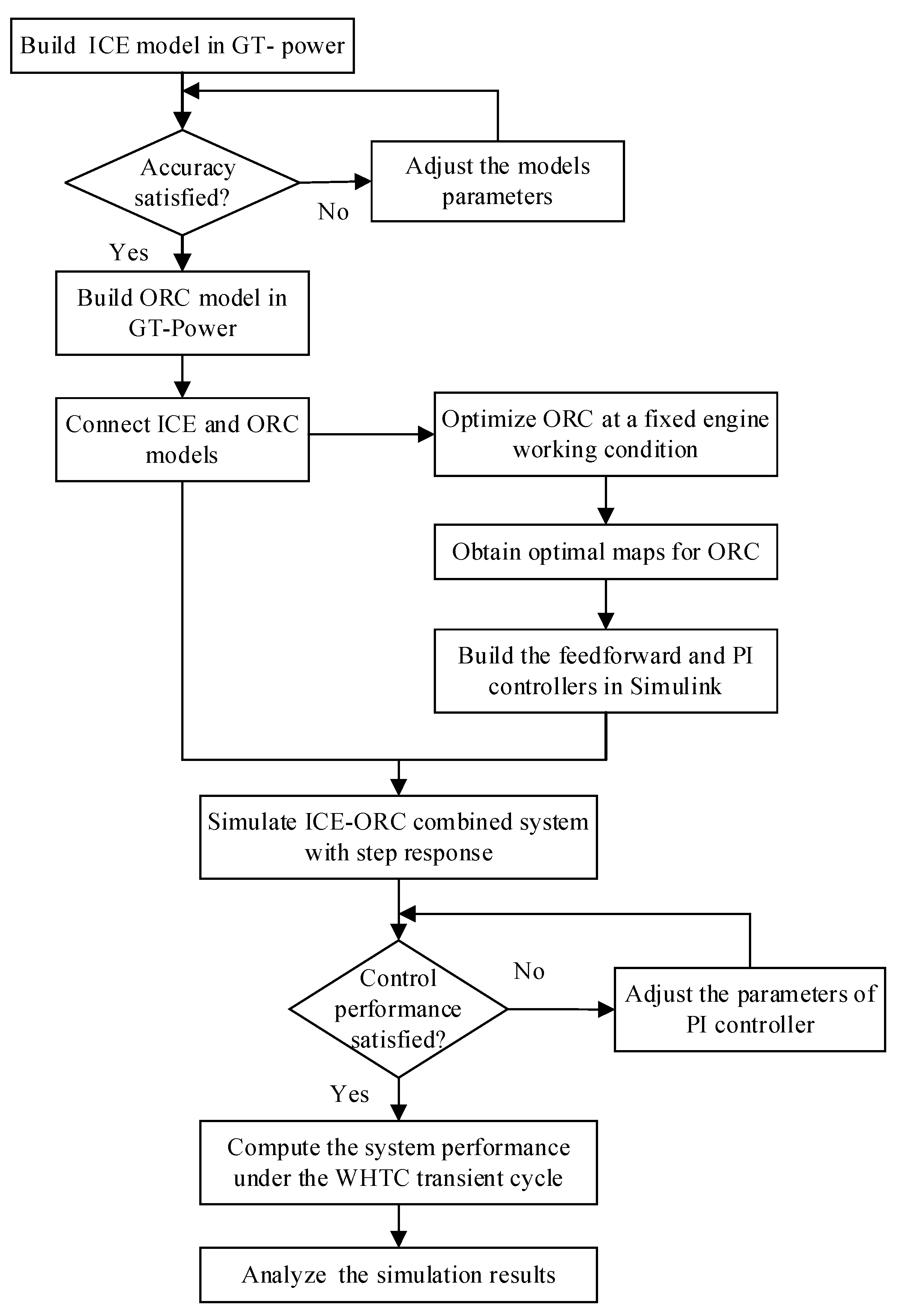
The operation conditions of vehicle engines are very complicated. When an ORC is used to recover the exhaust heat, it is difficult to match the ORC system with the engine over the entire driving conditions. In this study, a methodology for the design of an ORC controller is proposed for engine waste heat recovery. A flow chart of the design procedure is shown in
Figure 1. First, a high-fidelity dynamic model is set up for the engine in GT-Power [
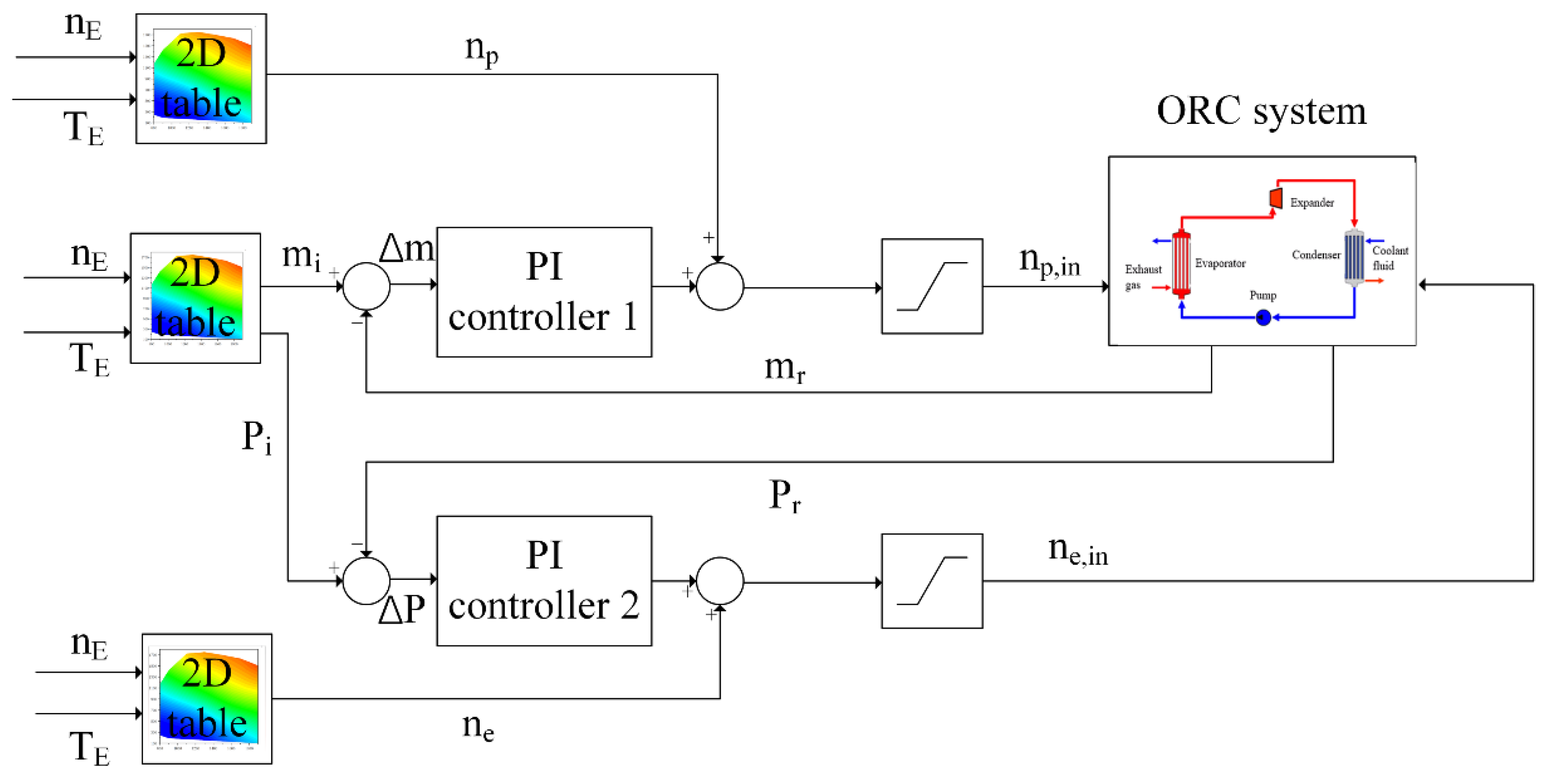
34] and experimental data are used to calibrate and validate the engine model. Then, a dynamic model of the simple ORC is designed in GT-Power. The optimal operation parameters of the ORC system are determined under various steady conditions of the engine and four maps are obtained for the evaporation pressure, the mass flow rate of the working fluid, the expander speed, and the pump speed. Subsequently, a dynamic control strategy is designed in Matlab/Simulink and an ICE-ORC combined system is established. In this study, a PI control together with a feedforward control is setup using the evaporation pressure and the mass flow rate of the working fluid as the controlled variables. The parameters of the PI controller are calibrated based on a step response. Finally, the control performance of the designed PI control is investigated based on a transient driving cycle. This methodology can provide a convenient and cheap method for the design of ORC controller. Thus, a lot of time and cost can be saved.
To evaluate the transient performance, a dynamic model of an ICE-ORC combined system is established. The model is divided into two parts: the ICE and the ORC system. The ICE model is built in GT-Power. The heat energy of the exhaust gases is sent to the ORC system as the heat source and the amount of the exhaust energy mainly depends on the mass flow rate and the temperature of the exhaust gases from the ICE. The second part is the ORC system, which functions as a bottoming cycle and converts the exhaust energy to useful work. In this study, a simple ORC configuration is used.
2.1. Internal Combustion Engine (ICE) Model
The ICE model is based on a heavy-duty turbocharged diesel engine and its main technical parameters are listed in
Table 1.
Because the structure and working conditions of the ICE are very complex, some necessary simplifications are assumed for the ICE model:
The model is independent of specific spatial coordinates of the system;
The working media in the cylinder is treated as ideal gas, and its state is governed by the conservation equations of mass and energy together with the equation of state of ideal gas;
The injected fuel burns completely and reaches the thermodynamic equilibrium state at each instant in the cylinder.
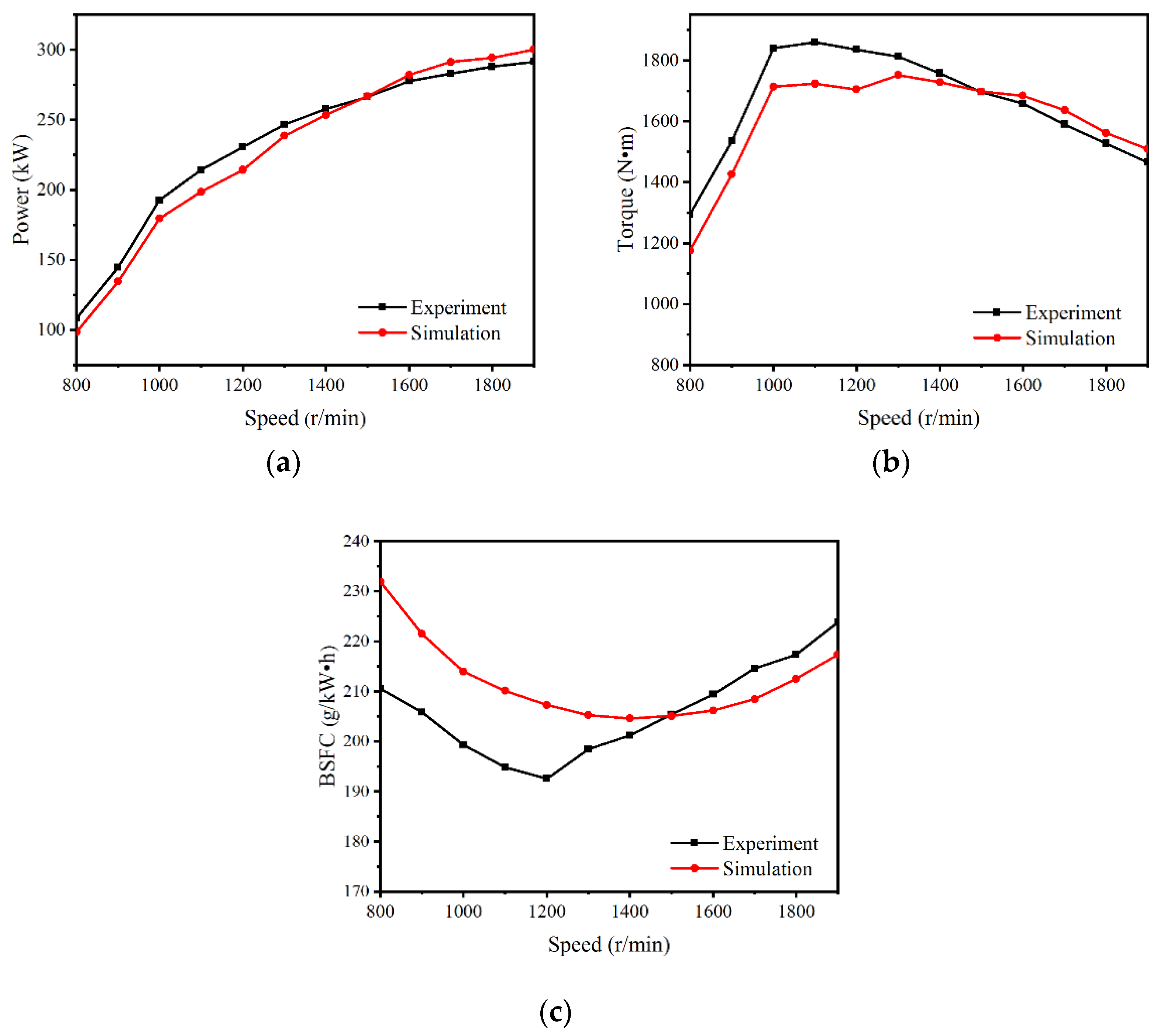
A quasi-steady 1D model is built in GT-Power, which can be expressed by several differential equations. The ICE model built in GT-power is simulated under the full-load conditions. The results are compared with the measured data from an engine test and shown in
Figure 2. It can be seen that the engine power, the engine torque, and the brake-specific fuel consumption (BSFC) are in good agreement with the experimental data. The deviations for most working conditions are less than 10%. Therefore, the accuracy of the ICE model is validated and can be used for the simulation of the ICE-ORC combined system.
2.2. Organic Rankine Cycle (ORC) Model
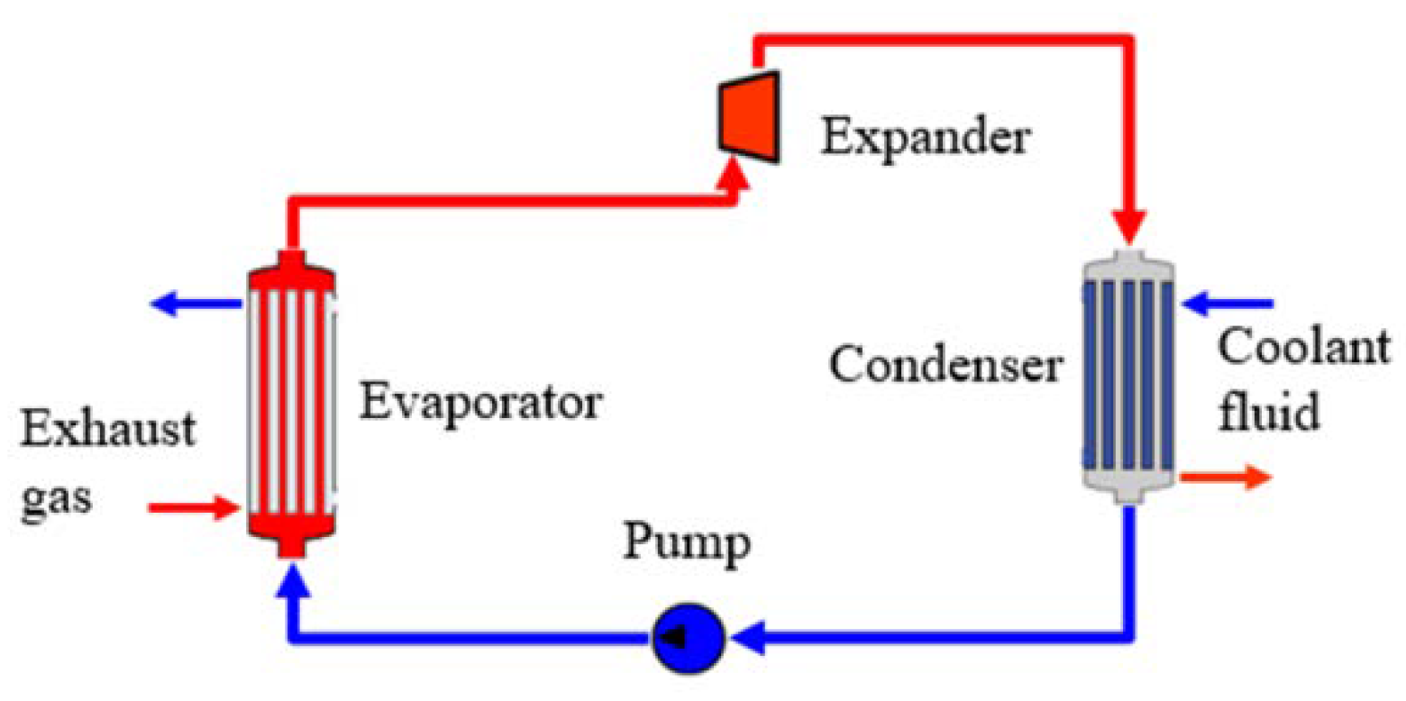
There are various configurations for ORC systems, such as the simple ORC, the ORC with a regenerator, the ORC with a reheater, the dual-loop ORC, and so on. Considering the complexity of the device, this study adopts the simple ORC, which is mainly composed of an evaporator, a condenser, an expander, and a pump.
Figure 3 shows the main structure of the simple ORC.
The evaporator is used to absorb heat from the exhaust gases so that the working fluid can be evaporated from a liquid state to a gaseous state. The high-pressure gaseous working fluid is transmitted to the expander to generate work. The condenser is used to condensate the working fluid to a low-pressure liquid state after expansion. The pump pressurizes the working fluid and outputs to the evaporator for the next cycle. Normally, the organic working fluid undergoes three different phases such as liquid, two-phase, and gaseous states inside the evaporator and the condenser. The working fluid of the ORC system is R245fa. The coolant of the condenser is a mixture of water and glycol with a mass fraction of 50/50. The properties of R245fa and the coolant are determined by the property module in GT-Power. The main parameters for the components of the ORC system under the nominal condition are listed in
Table 2.
For the single-phase region of the working fluid in the evaporator, the Dittus–Boelter correlation [
35] is used to determine the convective heat transfer coefficient.
where
h is the convective heat transfer coefficient,
Re is the Reynolds number,
Pr is the Prandtl number,
k is the thermal conductivity, and
d is the characteristic length.
In the two-phase region of the evaporator, the heat transfer is modelled by the Shah–Thome correlation [
36] and expressed by:
where
Nu is the Nusselt coefficient,
x is the quality,
P is the operation pressure of the working fluid, and
Pcr is the critical pressure. The subscripts
l and
rd represent liquid and reduced, respectively.
In the single-phase region inside the condenser, the heat transfer coefficient is determined by Equation (5) with an exponential of 0.3 for
Pr due to the change of viscosity of the working fluid.
In the two-phase region of the condenser, the heat transfer is modelled by the Yan–Lin correlation [
37] and expressed by:
where
ρ is the fluid density,
D is the reference length,
q is the heat flow rate, and μ is the dynamic viscosity.
The high-temperature gaseous working fluid from the outlet of the evaporator flows into the expander and changes to a low-pressure state, propelling the expander to spin and drive a generator to produce electricity. In this study, a single-screw expander is employed, which is the same as in reference [
29]. The measured data by [
38] are used for the modeling process in GT-Power. The pump is responsible for pressurizing the low-temperature liquid working fluid and then delivering it to the evaporator. The data in reference [
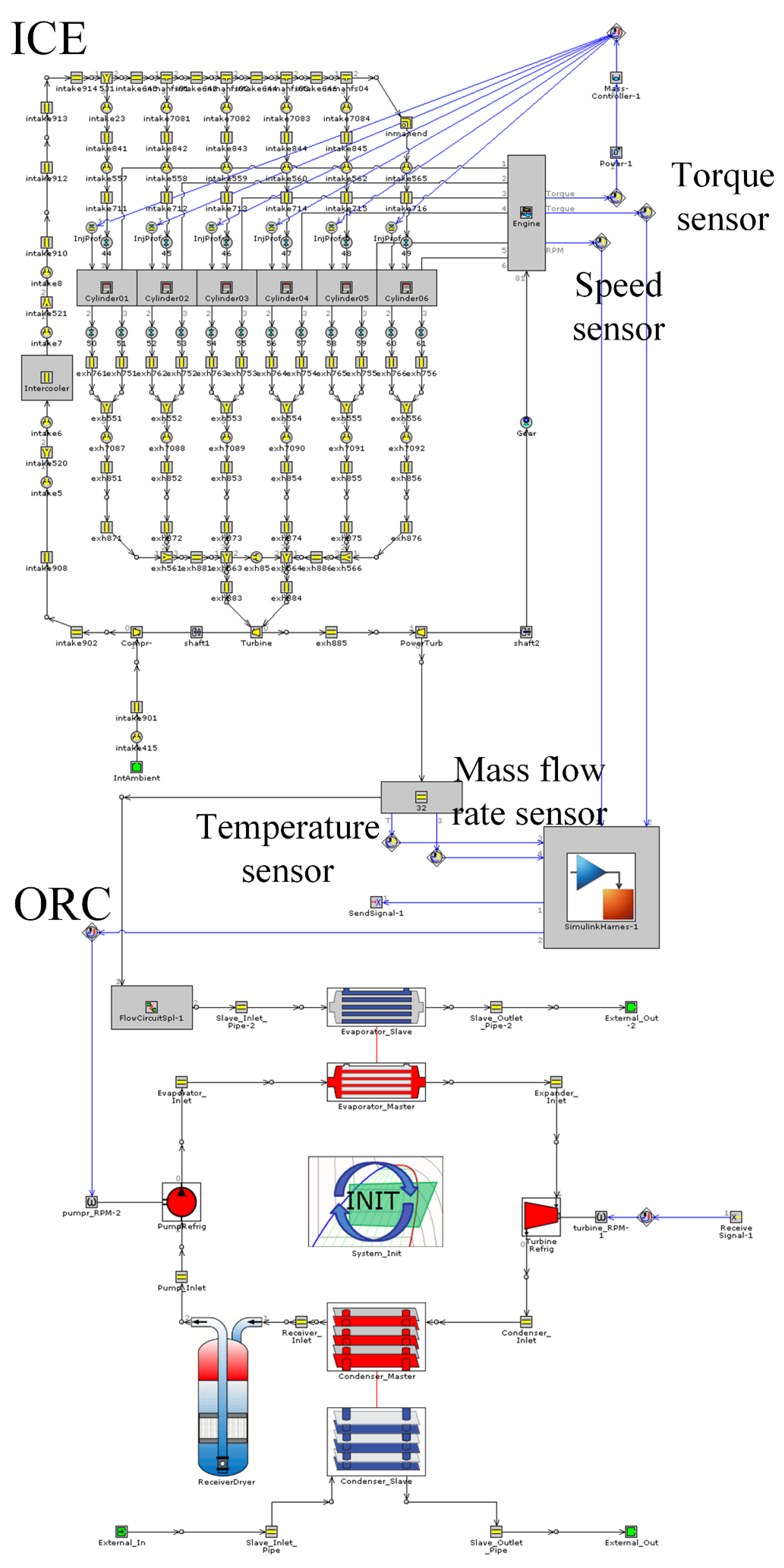
29] is used to model the pump. Finally, the ICE-ORC combined system is setup in GT-Power and
Figure 4 shows the model connection. The exhaust gases flow out of the turbine of the ICE and then enter into the evaporator of the ORC. In the GT-Power software, because the calculation algorithm of the ICE model is different from that of the ORC model, a splitter module is inserted between the turbine and the evaporator to synchronize the calculation process when coupling the ICE with the ORC. To control the operation of the ORC during the transient conditions, a Simulink module is added to implement the control strategy. The engine speed, the engine torque, the mass flow rate, and the exhaust temperature are sampled by the controller. According to the rotation speed and torque of the ICE, the target speeds of the single-screw expander and the pump are determined by the control algorithm. Then, these signals are sent to the ORC model to control the speeds of the single-screw expander and the pump.
3. Performance of ICE-ORC Combined System
The performance of the ORC system is mainly affected by two factors: the first is the amount of heat energy provided by the exhaust gases of the ICE, which is decided by the exhaust temperature and the exhaust mass flow rate; the second factor is the operating parameters of the ORC system, for example, the evaporation pressure, the evaporation temperature, the mass flow rate of the working fluid, etc. These parameters are normally controlled by the expander speed and the pump speed. To study the operation characteristics of the ICE-ORC combined system under dynamic conditions, it is necessary to estimate the match performance when the engine operating under different steady conditions. The allowable working speed of the engine is 800–1900 r/min. Under the low-speed region, the exhaust mass flow is too small, which has not enough exhaust energy to drive the ORC system. Hence, the working fluid at the outlet of the evaporator cannot be evaporated completely. If the working fluid enters the expander in a liquid-gaseous two-phase state, it will not be helpful for the durability of the expander and may cause damages to the expander vanes. In this study, the engine performance data are measured across the entire working scope. The engine speed of the ICE is set from 800 r/min to 1900 r/min in an interval of 100 r/min. The engine load of the ICE is set from 10% to 100% in an interval of 10%. Subsequently, 63 working points of the ICE are selected and the ORC performance is optimized under each working point of the ICE.
When the engine operates at a fixed point, the output performance of the ORC system will be affected by the working parameters of the ORC such as the mass flow rate, the evaporation pressure, the condensation pressure, etc., which can be regulated by the speeds of the expander and the pump. In this study, the operation range of the expander speed is set to 900–2400 r/min and the pump speed is set to 100–2500 r/min. Here, the working point with an engine speed of 1500 r/min and an engine load of 80% is used as an example to illustrate the optimization process of the ORC system when matching with the ICE.
Table 3 lists the working parameters of the ICE at this point, which are used as the input to the ORC system.
When the engine operates under a fixed point, the expander speed and the pump speed are tuned and the performance of the ORC system is recorded.
Figure 5 shows the results when the engine operates at 1500 r/min and 80% load. For a fixed working point of the engine, the available exhaust energy maintains at a certain value and the allowable mass flow rate of the working fluid needs to match with it. It can be seen that the range of the rotation speed of the pump is not covered the entire working scope of the pump. If the mass flow of the organic working fluid at the cold side of the evaporator is too small, the exhaust energy from the ICE cannot be fully utilized and the temperature of the working fluid will exceed the upper limit. On the other hand, if the mass flow of the working fluid is too high, the organic working fluid at the outlet of the evaporator cannot completely evaporate and the quality is less than 1, which is not conducive to the operation of the ORC system. Both situations are abnormal and should be avoided. The flow rate of the working fluid is mainly determined by the rotation speed of the positive displacement pump. Therefore, the rotation speed range of the pump is narrow for a fixed engine working condition. In this case, the allowable pump speed ranges from 1750 r/min to 2500 r/min. Meanwhile, the expander speed has a great influence on the performance of the ORC. In this case, its working range can cover the entire scope as 900–2400 r/min.
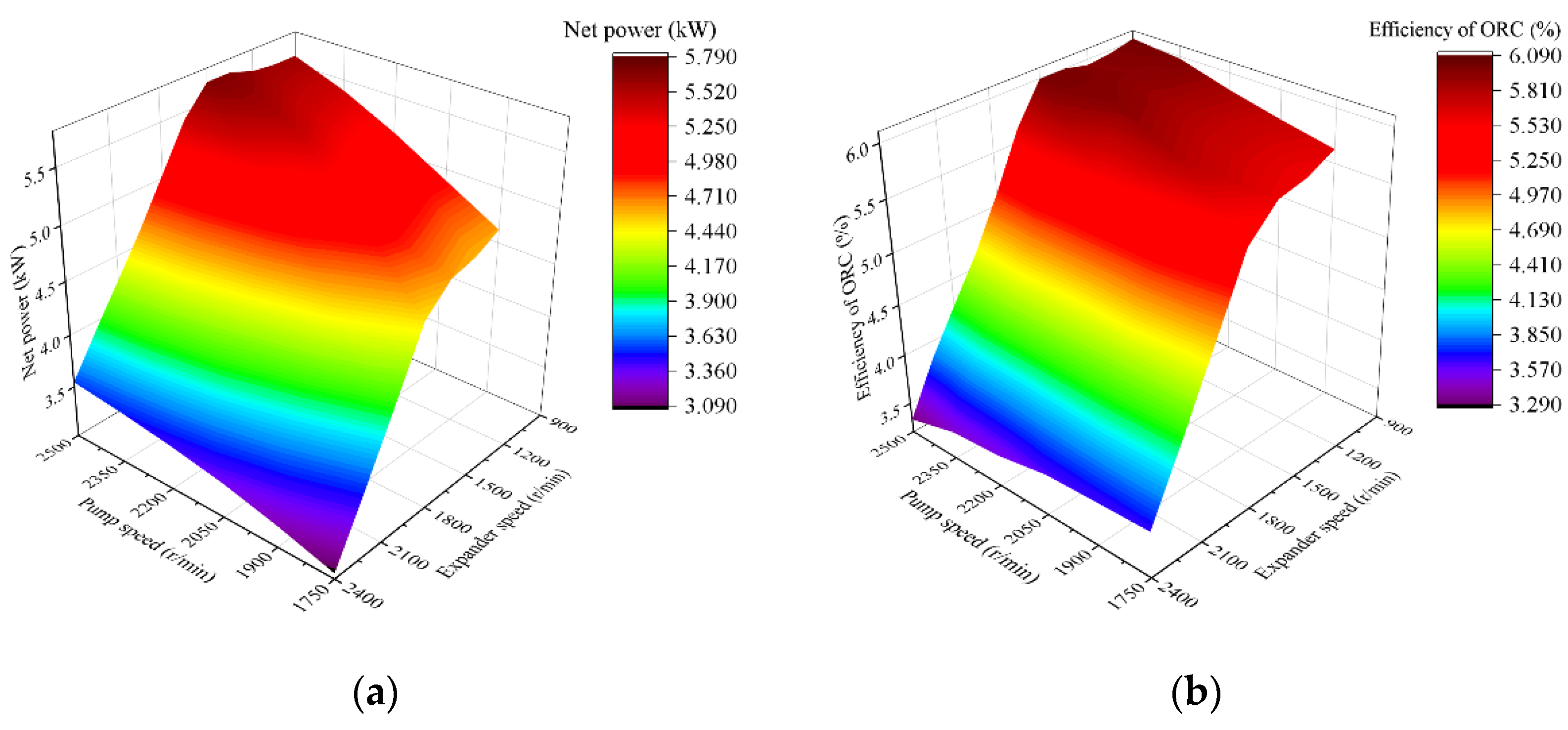
Figure 5a shows the net power of the ORC system as a function of the expander speed and the pump speed, which first increases obviously with the decrease of the expander speed, then arrives the peak and slightly decreases. The optimal expander speed is in the low-speed region. With the increase of the pump speed, the net power of the ORC system increases monotonously. Under the considered working point of the ICE, the optimal working condition of the ORC when the net power maximizes is obtained with an expander speed of 1500 r/min and a pump speed of 2500 r/min. The corresponding net power of the ORC system is 5.79 kW.
Figure 5b shows the thermal efficiency of the ORC system. The trend is similar to that of the net power. This is because the heat transfer of the evaporator keeps almost constant. The maximum thermal efficiency reaches 6.09%, which appears at the same point as the net power.
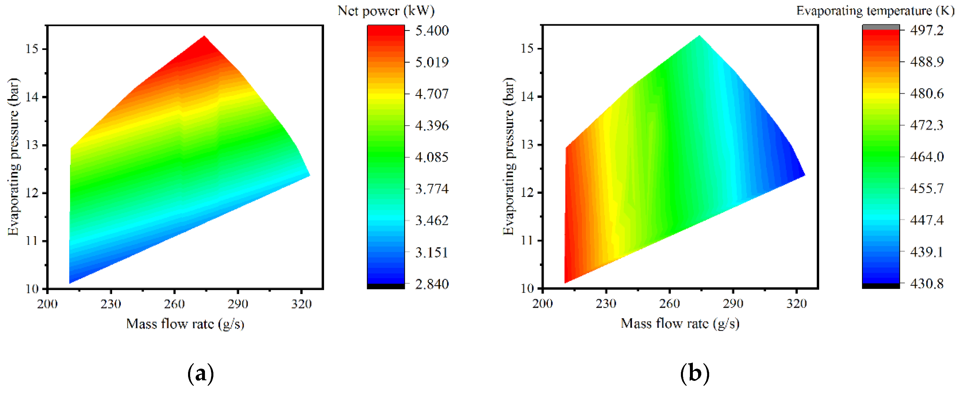
Figure 6a shows the effects of the mass flow of the working fluid and the evaporation pressure on the net power of the ORC system. The evaporation pressure has a significant influence on the net power. With the increase of the evaporation pressure, the net power rises rapidly. For the ORC system, the lower the rotating speed of the expander, the higher the evaporation pressure, the greater the enthalpy difference between the inlet and outlet of the expander, and the higher the output power, which also verifies that the net power is larger when the rotating speed of the expander is lower in
Figure 5a. Under the same evaporation pressure, the net power decreases slightly with the increase of the mass flow of the working fluid.
Figure 6b shows the influences of the evaporation pressure and the mass flow rate of the working fluid on the evaporation temperature. Here, the evaporation temperature is defined as the working fluid temperature at the outlet of the evaporator. The mass flow rate manifests a more significant impact on the evaporation temperature than the evaporation pressure. A negative correlation between the evaporation temperature and the mass flow can be found. The smaller the mass flow, the higher the evaporation temperature. Compared with
Figure 6a, we can see that the higher the evaporation pressure, the better the net power. However, the net power of the ORC system is not always kept high in the region with the highest evaporation temperature, because maybe the mass flow rate of the working fluid is too small to form a high evaporation pressure, and the evaporation pressure has a greater impact on the net power of the ORC system.
The performance of the ORC system under different engine working conditions was analyzed according to the above procedure. In fact, the operation conditions of the ICE may vary frequently during the driving process, especially in the urban road conditions. Therefore, it is meaningful to investigate the ORC performance over the entire engine’s working scope. In this study, 63 different working points across the entire engine operation scope were selected. The engine speed ranged from 800 r/min to 1900 r/min with an interval of 100 r/min and the engine load was between 10% and 100% with an interval of 10%. The performance of the ORC system can be determined at each working point using the same procedure described as the above case. Although the optimal performances of the ORC system are different under these working points of the ICE, the overall trends of the maps are similar to those of
Figure 5 and
Figure 6. After sorting out 63 simulation cases, the optimal operation parameters of the ORC system under each case can be obtained.
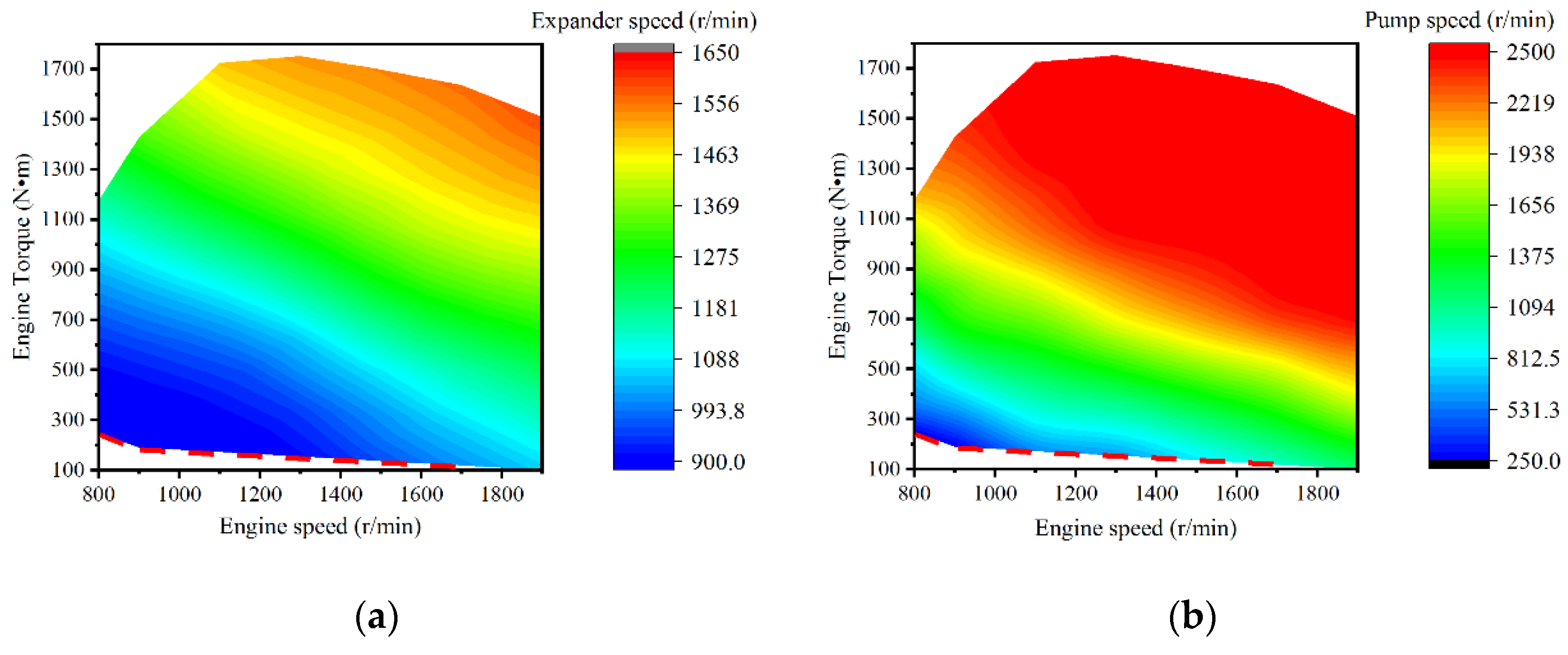
Figure 7 gives the optimal results of the expander speed and the pump speed when the ORC matches the ICE over the entire engine’s working scope. Comparing these two figures, it can be found that the variation trends of the optimal pump speed with the engine speed and the engine load are approximately the same as that of the expander speed. Both increase with the increase of the engine speed or the engine load. The optimal speed range of the expander is 900–1650 r/min, and the optimal speed range of the pump is 250–2500 r/min. Taking into account the designed operation ranges of the expander and the pump, it can be observed that the operation range of the expander is mainly located in the low- and medium-speed region, and the pump is concentrated in the high-speed region. This is because, as mentioned above, a lower expander speed can lead to a higher evaporation pressure. When the ICE operates under the conditions with a low-and-medium engine power, the optimal expander speed is about 900 r/min. As the engine power increases, the exhaust energy also enlarges and the optimal expander speed increases. When the engine operates at 1900 r/min with a full load, the maximum expander speed arrives at 1650 r/min. The optimal pump speed situates in the high-speed region over most of the operation scope of the engine because the exhaust energy is high enough under the medium and high engine-power conditions. In order to utilize the exhaust energy comprehensively and avoid the temperature of the working fluid exceeding the critical temperature, the mass flow of the working fluid should be increased to a high level. As a result, the pump needs to operate with a high speed. In the case of a small exhaust energy, the pump speed decreases to keep the mass flow rate smaller such that the working fluid can be evaporated completely. The red dashed lines of the two maps represent the shutdown boundary for the ORC system. The engine load is close to 10% along the red lines. At this moment, the efficiency of the ORC system is very low. When the engine operation condition is below the red line, the ORC system stops. Compared with the results of Liu et al. [
29], the maps in
Figure 7 display a smoother variation. The reason can be explained as follows. The exhaust energy of the engine is small in Liu’s study, the optimal operation ranges of the pump and the expander locate in the low-speed regions. As a contrast, an engine with a much higher power output is considered in this study. Meanwhile, the considered engine working points are increased significantly in this study. Therefore, the operation ranges of the expander and the pump are extended significantly.
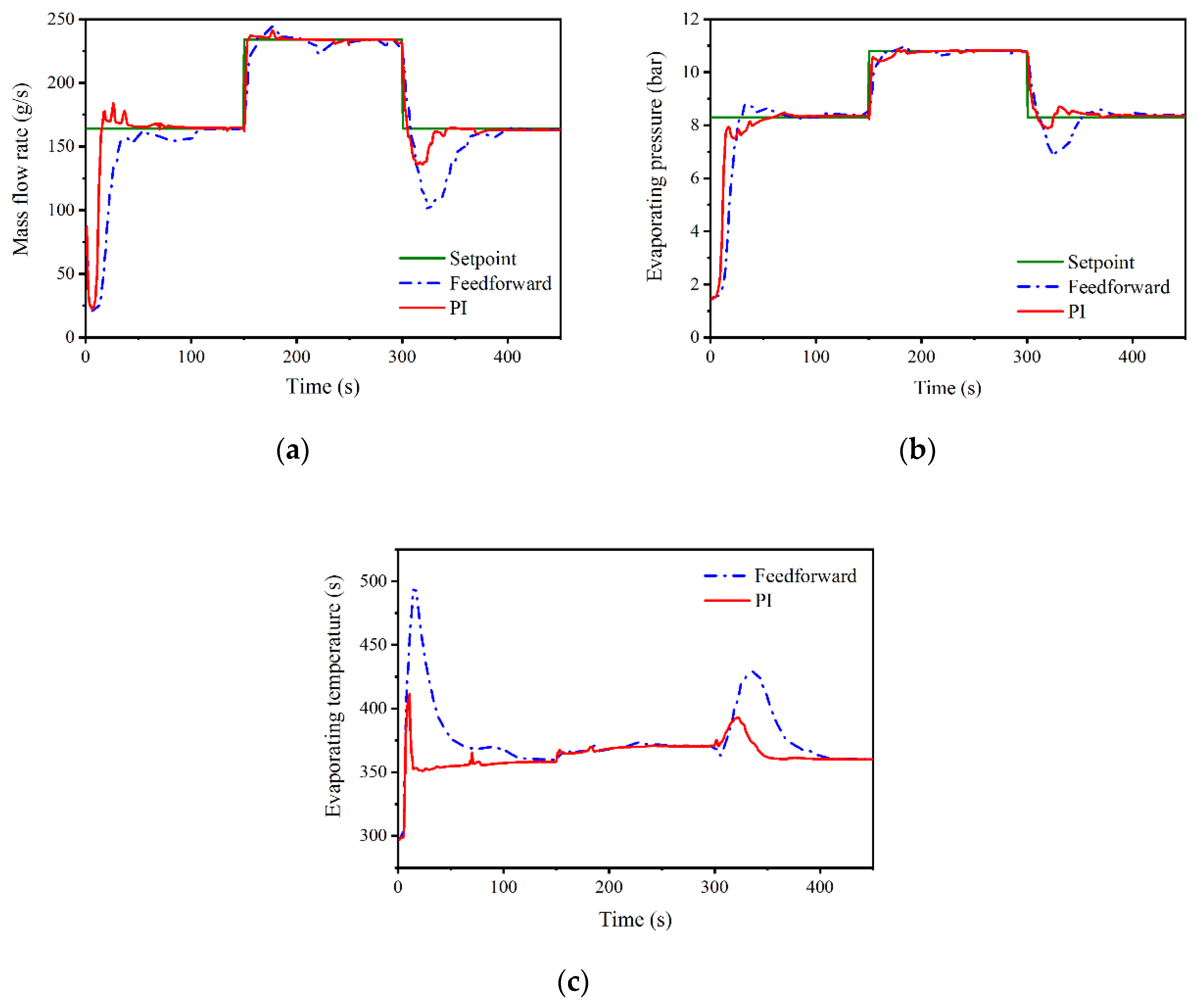
5. Performance under World Harmonized Transient Cycle (WHTC)
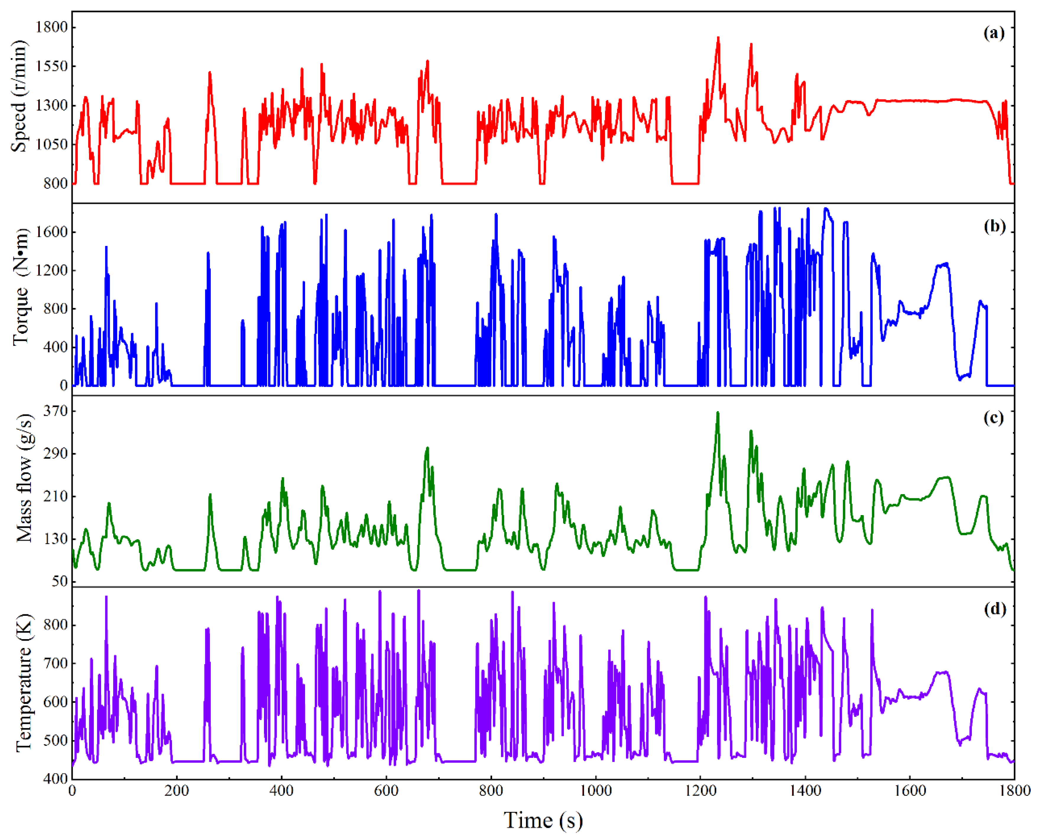
The actual road conditions are far more complex than the step response. Therefore, the WHTC transient driving cycle with a time length of 1800 s is used as a case study to analyze the performance of the designed control strategies. The profiles for the engine speed and the engine torque are determined according to the requirements of the WHTC transient cycle. Subsequently, the results for the mass flow rate and the temperature of the exhaust gases are calculated by the ICE model built in GT-Power.
Figure 11 shows the results as a function of time. The variation trend of the exhaust temperature basically follows the trend of the engine torque, which oscillates more dramatically during the driving cycle. The variation frequency of the mass flow rate is much smaller and shows a strong correlation with the engine speed. The range of the exhaust mass flow rate is between 50 g/s and 370 g/s, and the variation range of the exhaust temperature is 450–900 K.
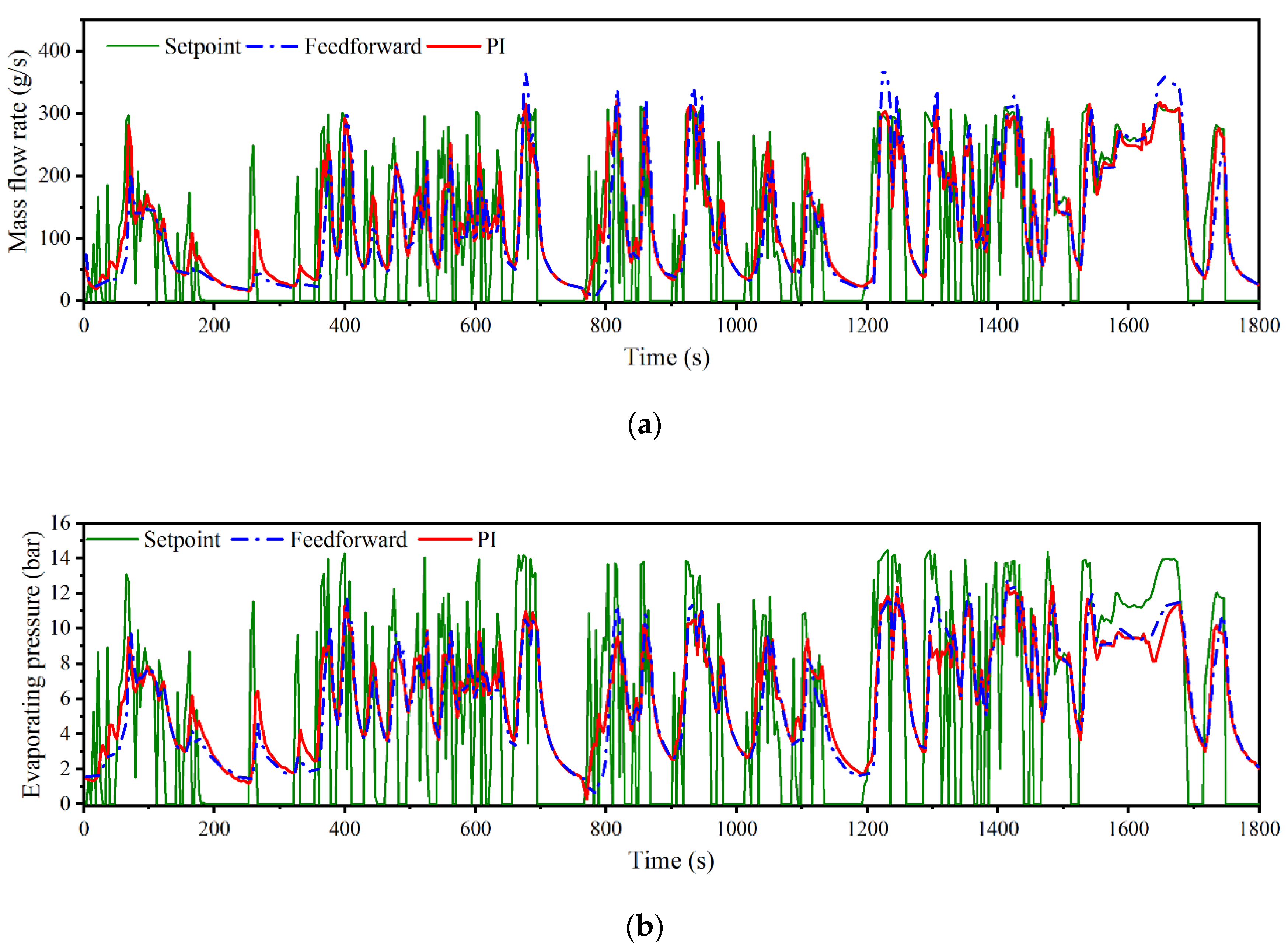
Figure 12 shows the results for the two controlled variables–the mass flow rate of the working fluid and the evaporation pressure. In this figure, the profile labelled with setpoint is determined based on the static simulation results of the former 63 operating points of the ICE. A linear interpolation algorithm is used to calculate the specific value during the transient driving cycle. Because the frequent changes of engine working conditions, the corresponding mass flow rate and the evaporation pressure of the setpoint profile also change dramatically. The results of the PI control and the feedforward control are displayed as the thick red line and the thick blue dash-dotted line. The mass flow rate varies in a large range from 20 g/s to over 300 g/s. The average mass flow rate under the high-way conditions is greater than that of the urban driving conditions apparently. The evaporation pressure changes from 1 bar to 12 bar during the driving cycle. The average evaporation pressure for the urban conditions is about 4 bar while this value increases to 8 bar for the high-way conditions.
Compared with the profile of the setpoint, the profiles of the two control strategies are much smoother and the practical variation frequencies are much lower. This is because thermal inertia exists in the ORC system and the mass inertia of the pump and the expander also cause a time delay. This time delay prevents the ORC system following the variation of the engine working conditions immediately while it is helpful for the continuous operation of the ORC system. Basically, the two control strategies show a similar variation trend. However, the closed-loop PI control has a better trace performance for the mass flow rate than the feedforward control. A large overshoot of the mass flow rate by the feedforward control can be observed. The advantage of the PI control for the evaporation pressure is less obvious because the response time of the evaporation pressure is much longer than that of the mass flow rate, which is about two times of the response time of the mass flow rate.
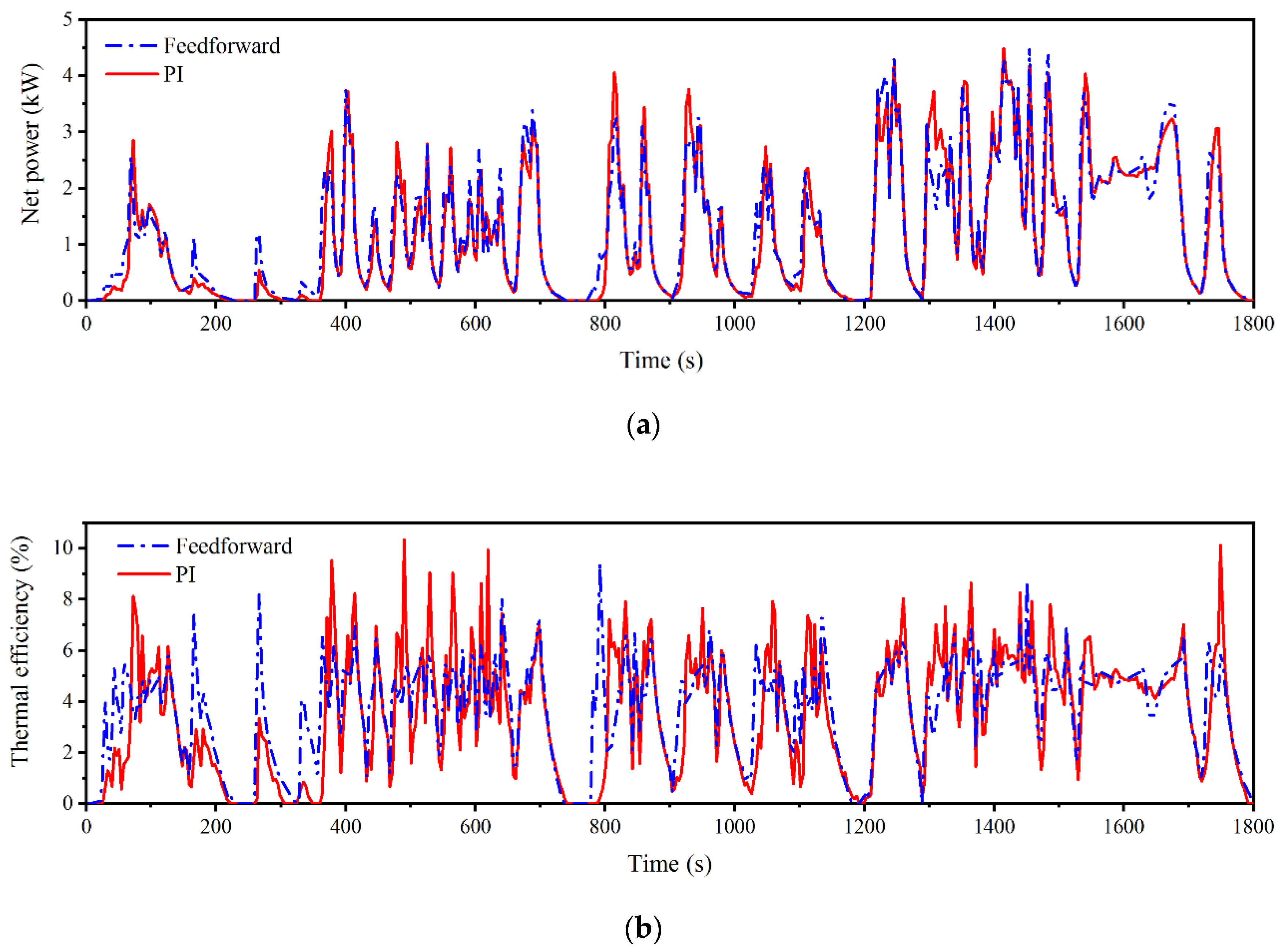
The net power and the thermal efficiency of the ORC system during the WHTC transient cycle are shown in
Figure 13, which manifest a similar variation trend with that of the mass flow rate or the evaporation pressure. The net power of the PI control is slightly better than that of the feedforward control for most of the time as displayed by
Figure 13a. During the transient driving cycle, the net power varies from 0 to 4.5 kW. The average net power during the high-way conditions is about 3 kW, which is much greater than that of the urban conditions as 1.5 kW. The variation of the thermal efficiency of the ORC system is shown in
Figure 13b. The results of the PI control show a higher response time during the driving conditions when the engine power is high. The peak value for the thermal efficiency is also greater than that of the feedforward control during these regions. The maximum thermal efficiency of the PI control exceeds 10% while the thermal efficiency of the feedforward control is less than 8% for most of the operation time. This is because the feedback part calculated by the PI control can compensate part of the errors of the mass flow rate during the transient process and the accuracy is improved accordingly.
Table 6 shows a comparison of the output work and thermal efficiency of the ORC system. The overall WHTC transient driving cycle can be divided to three phases: the urban phase, the suburb phase, and the high-way phase. Each phase takes up 600 s. The ORC performance is improved apparently for the PI control under the urban driving conditions. This is because large fluctuations of the input parameters occur and the PI control can accelerate the response of the ORC system accordingly. For the high-way conditions, the improvement of the PI control is very small, meaning the feedforward control can lead to an acceptable performance under the relatively slow transient processes. During the overall period, the output work of the ORC system using the PI control strategy is increased by 3.23% and the average thermal efficiency is increased by 2.77% compared with the feedforward control.


