Abstract
A thermo-economic analysis of a regenerative dual-loop organic Rankine cycle (ORC) is conducted, which will be coupled with the main diesel engines of a general support vessel. An energy and exergy analysis of the regenerative dual-loop ORC is conducted. The energy and exergy analysis results of the regenerative dual-loop ORC are compared with pertinent results for a simple dual-loop ORC without regeneration. A mission analysis that was based on a vessel speed profile with the proposed ORC was conducted. A heat transfer analysis was performed for dimensioning the heat exchangers of both ORC loops. Finally, an economic analysis is conducted to calculate the total capital cost and the payback period of the proposed ORC. The results showed that the proposed ORC is thermodynamically superior in both energetic and exergetic terms compared to the simple dual-loop ORC. The total fuel cost saving is 337,493 Euros, the total CO2 emission saving is 1,153,416.4 kg, and the SO2 emission saving is 36,044.3 kg. The total capital cost of the proposed ORC is 2,546,000 Euros. Finally, the installation of the proposed ORC in the examined vessel is economically feasible because it results in a reasonable payback period, which is less than nine years.
1. Introduction
Contemporary marine diesel engines that are currently used in naval vessels as main engines or auxiliary engines are characterized by high efficiency, which is higher when compared to marine gas turbines and marine steam turbines [1]. Specifically, the brake efficiency of a modern four-stroke marine diesel engine is close to 50% of the fuel heating power, whereas almost the 30% of the fuel heating power is rejected to the ambient through hot exhaust gases [2]. The remaining fuel heating power, which is not converted to useful brake power and exhaust gas heating power, is rejected to the engine coolant, to the cooling medium of the intercooler, and to the lubricant oil cooler, whereas a small percentage of the fuel heating power is rejected to the ambient through radiative heat transfer thermal losses [3].
Various technologies have been proposed in the literature for the utilization of waste heat from marine diesel engines [3]. Specifically, Singh and Pedersen [4] have analyzed the specifications and the advantages and disadvantages of a water steam Rankine cycle, a subcritical Rankine cycle, and a supercritical organic Rankine cycle. They have also examined the use of a secondary Kalina cycle with the ammonia–water mixture as working medium as an alternative thermodynamic cycle for the waste heat recovery from marine engines [4]. Singh and Pedersen have also examined the technology of thermoelectric generators for the recovery of waste heat from marine engines and its conversion to useful electric energy [4]. One of the most promising waste heat recovery technologies from marine diesel engines and, in general, from internal combustion engines is Rankine cycle, which comprised of two separate loops: a high temperature (HT) loop and a low temperature (LT) loop, as evidenced from this review paper [4]. In the HT loop a heat exchanger to transfer waste heat from hot exhaust gases to a wet or a dry working medium is used, which then expands in the HT loop expander. “Wet” is defined the working medium that expands inside the two-phase area, whereas as “dry” is defined as the working medium that its expansion leads to the superheated area [4]. A characteristic “wet” working medium is the water steam, which expands inside the two-phase area due to the shape of the saturation curve, whereas many organic working mediums are characterized as “dry” ones, since the sloped saturation curve force them to expand inside the superheated region [4]. In the LT loop, the recovery of lower grade waste heat as compared to exhaust gases is conducted from engine coolant and from the cooling medium of the intercooler and generation of additional power in the LT loop expander. Liu et al. [5] investigated the thermodynamic performance of various organic Rankine cycle (ORC) configurations and compared them with a theoretical optimum reversible Rankine cycle in order to determine the optimum practical Rankine cycle between the high and the low temperature heat sink. Liu et al. [5] also thermodynamically investigated the following organic Rankine cycle configurations: basic ORC, supercritical ORC, regenerative ORC, split regenerative ORC, cascade ORC, and two-pressure stage ORC. They found from this comparison that the two-pressure stage ORC indicated the highest relative efficiency when compared to the theoretical reversible ORC between the two heat sinks. For this reason, various configurations of dual-loop ORCs have been used in many applications of internal combustion engines. Specifically, Andreasen et al. [6] performed a comparative analysis of a dual-loop Rankine cycle with water steam with a pertinent ORC in order to recover waste heat from a main diesel engine of a container ship. These results showed that the net generated power of the steam Rankine cycle is higher when compared to the corresponding one of the ORC at high engine loads whereas, at low engine loads the operational performance of the organic Rankine cycle is superior as compared to the corresponding one of the steam Rankine cycle [6].
Li et al. [7] proposed the use of a two-stage ORC for the exhaust gas heat recovery in a HT loop with expander and regenerator and a LT loop with second expander. Five organic mediums were examined in this study [7] and, specifically, toluene, benzene, cyclohexane, and R245fa for the generation of additional power in the two expanders of the dual-loop organic cycle, which was coupled to a diesel engine with 13 L capacity. The assessment of the results of this study [7] have showed that, as the effectiveness of the regenerator is increased, the thermal cycle efficiency and the net generated power are increased, since, in this case, exhaust gas temperature at the exit of the evaporator is increased.
Shu et al. [8] proposed an ORC system that is based on the most typical operational status of a vessel. The results of this study [8] showed that the R123 is more suitable for the generation of additional power at high engine load, whereas the R365mfc is more suitable for the generation of additional power at part engine load. Shu et al. [9] thermodynamically analyzed a dual-loop ORC, which comprised of a HT loop for exhaust gas heat recovery and a LT loop for heat recovery from engine coolant and from the HT loop. The dual-loop ORC was combined with an inline six cylinder four-stroke turbocharged engine. R124, R134a, R245fa, R600, and R1234yf were examined as potential organic mediums of the dual-loop ORC [9]. The evaluation of the results showed that the R1234yf was found to be superior when compared to other organic mediums at high engine load in terms of generated power, cycle thermal efficiency, and total efficiency of the combined installation, whereas R124 indicates the worst behaviour at all engine loads [9].
Song et al. [10] examined two different ORC configurations for the waste heat recovery from engine coolant and from exhaust gases. In this study [10], an optimized system was demonstrated, which uses the engine coolant for the preheating of the organic medium and the exhaust gases of the engine for the evaporation of the organic medium. The results of this theoretical analysis [10] showed that the optimized system is technically feasible and economically attractive.
Song and Gu [11] proposed a dual-loop ORC for the waste heat recovery from an inline six-cylinder turbocharged diesel engine. The proposed dual-loop ORC is comprised from a HT loop for exhaust gas heat recovery, whereas a LT loop is used for the waste heat recovery from engine coolant and the waste heat recovery from the HT loop in order to generate additional power in a second expander [11]. Cyclohexane, benzene, and toluene were chosen as working mediums of the HT loop, whereas R123, R236fa, and R245fa were chosen as the working mediums of the LT loop. When cyclohexane is used as working fluid in the HT loop and R245fa is used as working fluid in the LT loop, the dual-loop ORC can increase the overall generated power of the combined system by 11.2% when compared to the conventional diesel engine operation [11].
Song and Gu [12] again examined the dual-loop ORC, which was coupled with an inline six-cylinder diesel engine. The HT loop of the Rankine cycle operated with water as working medium, which expanded inside the two-phase area through a screw expander whereas, R123, R236fa and R245fa were examined as organic mediums for the LT loop, which recovers rejected heat from engine coolant and from the HT loop [12]. The results of this theoretical investigation showed that the maximum generated power of the Rankine cycle was 115.1 kW, which resulted in an increase of the overall generated power of the combined system of the diesel engine and the Rankine cycle of 11.6% [12].
Sung and Kim [13] designed a new system of dual-loop ORC for a dual-fuel (natural gas/diesel) marine compression ignition (CI) engine. The organic medium in the HT loop of the ORC recovers waste heat from the exhaust gases, whereas the organic fluid in the LT loop recovers waste heat from the engine coolant and from the cold side of the liquefied natural gas (LNG) [13]. The optimization of the system showed that the preheater and the evaporator with normal pentane and R125 as working mediums resulted in an increase of the maximum generated work by 5.17% when compared to the initially generated work of the dual-fuel CI engine [13].
Yao et al. [14] examined the use of a dual-loop ORC for the waste heat recovery from a heavy-duty CNG engine and they found that the percentage increase of power and maximum improvement of specific fuel consumption (sfc) was 33.73% and 25% as compared to the conventional operation of the CNG engine. Zhang et al. [15] examined a small-scale dual-loop ORC for the waste heat recovery from a small diesel engine and they found that the generated power of the LT loop was higher when compared to the corresponding one of the HT loop and the generated power was increased from 14% to 16% in the area of the peak thermal efficiency and by 38% to 43% in the area of low engine load [15]. Zhao et al. [16] used GT-SUITE software for the development of a diesel engine simulation model and they also developed a simulation model of the ORC system and then they combined the two simulation models in the Simulink. Zhao et al. [16] found that the peak generated power varied from 5.47 kW at 1500 rpm to 7.07 kW at 2100 rpm, whereas the back pressure at the engine exhaust was increased with the temperature increase of the coolant water due to the Rankine cycle operation. Zhou et al. [17] conducted a thermodynamic analysis a dual-loop ORC that was coupled with a diesel engine. The zeotropic mixtures RC318/R1234yf, butane/R1234yf και RC318/R245fa were chosen as working mediums of the Rankine cycle [17]. The analysis of the theoretical results showed that the appropriate mixture does not only improve the thermal efficiency, but also the absorbed heat from heat sources in the low temperature loop. With RC318/R1234yf as working fluid in the low temperature loop, the engine output can be improved by nearly 14.4%. [17].
Yang et al. [18] performed a thermodynamic and economic study of a dual-loop ORC system coupled with a CNG engine. Specifically, Yang et al. [18] performed a detailed thermal analysis for dimensioning all of the heat exchangers of the ORC system and they also conducted an economic analysis for calculating the investment cost of the dual-loop ORC system and the cost of the generated electric energy. At maximum engine power, the maximum generated power from the dual-loop ORC system was 23.62 kW and the lowest cost of the generated electric power was 0.41 $/kWh [18]. The thermal efficiency of the dual-loop ORC system varies from 8.97 to 10.19% at the entire engine operational range.
Another interesting study was performed by Scardigno et al. [19], which adopted a genetic algorithm for performing a multi-objective optimization of a hybrid organic Rankine cycle for solar and low-grade energy sources. The main objectives of the genetic optimization method were the maximization of the first and second law efficiencies of the cycle and the minimization of the levelized energy cost. The theoretical results of this analysis showed that the lowest energy cost and the highest first law efficiency were attained using cyclopropane, whereas the highest second law efficiency was achieved by employing R143a.
Hence, from the detailed examination and analysis of the available literature regarding the implementation of the dual-loop ORC in internal combustion engines, the following observations can be made:
- The use of a dual-loop ORC for the recovery of waste heat from exhaust gases, engine coolant, and intercooler of the main engines of a naval vessel, such as a general support vessel, has not been examined up to now.
- The simple dual-loop ORC with a regenerative dual-loop ORC has not compared up to now in order to determine the deviations between the two cycles in both energetic and exergetic performance parameters.
- It has not examined up to now the fuel, CO2 and SO2 savings during a mission analysis of a general support vessel equipped with a regenerative dual-loop ORC coupled to its main engines.
- It has not been implemented up to now a detailed thermal analysis for dimensioning the heat exchangers of the regenerative dual-loop ORC, which is coupled with the main engines of a general support vessel.
- It has not been implemented up to now an economic analysis to predict the capital cost of the ORC installation, the cost of generated electric energy, and the payback period of the regenerative dual-loop ORC investment.
Hence, in the present study, an energy and exergy analysis are performed for a dual-loop ORC coupled to the main diesel engines of a general support vessel. Additionally, an energy and exergy analysis of a regenerative dual-loop ORC equipped with an Open Feed Organic Heater (OFOH) in both HT and LT loop, which is also coupled to the main engines of a general support vessel, is conducted. The energetic and exergetic performance results of the simple dual-loop ORC and the regenerative dual-loop ORC are compared in order to specify the optimum thermodynamic cycle to be used for the waste heat recovery from the exhaust gases, engine coolant, and intercooler of the main engines of the examined general support vessel. R245fa and R600 are examined as organic fluids of the HT loop of both simple and regenerative dual-loop ORCs due to their improved thermal stability at high exhaust gas temperatures, whereas R245fa, R600, R1234yf, and R1234ze are examined as working mediums of the LT loop of both examined dual-loop ORCs. A parametric study considering the effect of various thermodynamic parameters of the HT and the LT loop for all possible combinations of the organic fluids considered in the present study is performed. A mission analysis of the general support vessel equipped with the combined system of the main engines and the regenerative dual-loop ORC is performed in order to predict the economic benefit from the fuel savings and also the predict the CO2 and SO2 savings. A detailed heat transfer analysis is conducted for dimensioning the exhaust gas heat exchanger of the HT loop and the heat exchangers that harvest waste heat from the HT loop organic fluid at the preheater, the engine supplied air at the LT loop intercooler, the engine coolant at the LT loop, and the LT loop condenser. Finally, an economic analysis is conducted in order to estimate the cost of the ORC system components, the cost of generated electric energy, and the overall investment cost of the regenerative dual-loop ORC while taking the mission analysis revenues from fuel savings and the maintenance and insurance cost of the regenerative dual-loop ORC into consideration.
2. Brief Description of the General Support Vessel and its Main Propulsion and Electric Power Generation System
In the present investigation, the installation of a regenerative dual-loop ORC with OFOH in a general support vessel of the Greek Navy is proposed. The deadweight of the examined general support vessel is 13,400 tones and it is equipped with two main turbocharged direct injection (DI) twelve-cylinder diesel engines [20]. The Maximum Continuous Rating (MCR) of each main diesel engine is 8640 kW at 510 rpm [21]. More details regarding the main diesel engine performance characteristics cannot be released due to confidentiality reasons. The maximum speed of the specific general support vessel is 21.5 knots [20]. It is proposed the installation of the regenerative dual-loop ORC system in the engine room of the examined general support vessel due to space availability. It is also proposed that the regenerative dual-loop ORC system to operate at constant vessel speed and at steady operating conditions in order to avoid potential back pressure problems to the main engines turbocharging system from excess fouling of the exhaust gas heat exchanger during transient engine operation. The examined general support vessel is equipped with three auxiliary diesel generators. The generated power of each diesel generator is 872 PS and its corresponding sfc is 224 g/PSh [21].
3. Organic Fluid Description and Selection
The proper selection of the organic medium plays a very important role in the design of the ORC system. Organic fluids with low evaporation temperature are often preferred for the waste heat recovery from medium and low-grade thermal sources, such as the ones of internal combustion engines (mean temperature of exhaust gases and low temperature of engine coolant and charged air) [22]. Refrigerants and hydrocarbons are two commonly used working fluids for ORC systems. The organic fluid that will be selected for an ORC system should not be corrosive, flammable, and toxic when considering the ORC installation safety limitations and the environmental repercussions of the organic fluid [21]. Hence, chlorofluocarbons (CFCs) and hydrochlorofluorocarbons (HFCs) are not considered as candidate working mediums for ORC systems due to their high Global Warming Potential (GWP) and their high Ozone Depletion Potential (ODP) [22]. In addition, the present study does not examine the use of a “wet” working medium such as water/steam, which expands in the two-phase area as a liquid/steam mixture because the high-pressure ratio expansion of liquid droplets in the expander might result in the corrosion of the rotating expander blades [22]. Recent detailed studies have shown that R245fa [9,22,23,24,25,26,27,28] and R600 [9,26] have been utilized as working mediums in a broad range of ORC system applications. In addition, traditional refrigerants are replaced by hydrofluoroolefins (HFOs), which are new and environmentally friendly refrigerants with zero ODP and very low GWP, according to the current practice. Hence, based on all aforementioned reasons, four organic fluids, namely: R245fa, R600, R1234yf, and R1234ze, were chosen to be used in the dual-loop ORCs, which are examined in the present study. Table 1 presents the critical pressure and temperature, the ODP, and the GWP of the previously mentioned organic fluids.

Table 1.
Critical pressure and critical temperature, Ozone Depletion Potential (ODP) and Global Warming Potential (GWP) of the four working fluids that are examined in the present study [18].
4. Regenerative Dual-Loop Organic Rankine Cycle
Description of the Regenerative Dual-Loop Organic Rankine Cycle
In Figure 1 the schematic view of the regenerative dual-loop ORC with OFOH is shown, which includes the HT and LT loop, and it was considered in the present study. The HT loop has been designed to recover waste heat from the exhaust gases of the diesel engine, whereas the LT loop is used to recover rejected heat from the engine coolant network, the engine intercooler and the condenser of the HT loop, which is used as preheater for the organic fluid of the LT loop.
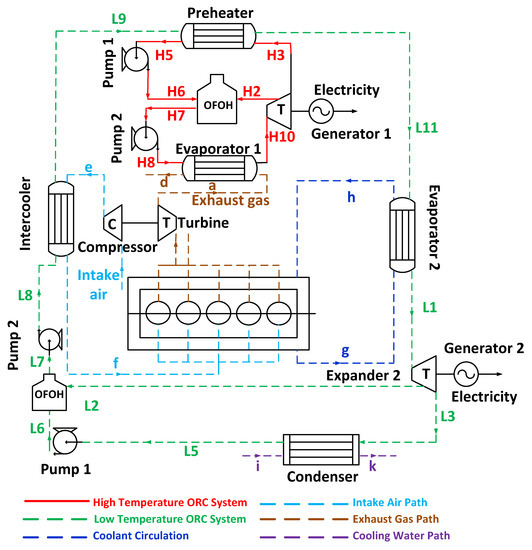
Figure 1.
Schematic view of the regenerative dual-loop organic Rankine cycle (ORC) with Open Feed Organic Heater (OFOH).
The HT loop of the regenerative dual-loop ORC comprised of an evaporator (evaporator 1), where the organic medium utilizes waste heat from the hot exhaust gases, an expander (expander 1), a preheater, two circulation pumps (pump 1 and pump 2), and an OFOH, where the hot stream and the cold stream of the organic fluid are mixed. The superheated organic steam expands up to an intermediate pressure in the expander 1 and, then, part of the expanded organic fluid flow rate is extracted from the expander 1 and is transferred to the OFOH to preheat the “cold stream” of the organic fluid, which comes out of the preheater and goes in the evaporator 1, whereas the remaining organic fluid flow rate expands up to low condensation pressure of the HT loop.
The LT loop of the regenerative dual-loop ORC comprised of an evaporator (Evaporator 2), where the organic fluid utilizes rejected heat from the engine coolant, an expander (Expander 2), a condenser, where the organic fluid rejects heat to the cooling seawater, two circulation pumps (pump 1 and pump 2), the engine intercooler, where the organic fluid recovers waste heat from the charged air, and an OFOH, where the hot stream and the cold stream of the organic fluid are mixed. Additionally, in the expander of the LT loop the saturated organic steam is expanded up to an intermediate pressure and at this pressure part of the organic mass flow rate is extracted from the expander and then transferred to the OFOH as “hot stream” and it is used to preheat the “cold stream” of the organic medium that comes out of the condenser of the LT loop. The remaining organic mass flow rate is expanded up to the low condensation pressure of the LT loop.
Figure 2 shows the thermodynamic processes that undergoes the organic fluid in the HT loop in a temperature–entropy diagram. In the HT loop, the subcooled organic fluid at state H8 that enters evaporator 1, where it recovers waste heat from engine’s exhaust gases and it is heated until it becomes superheated steam at the exit of evaporator 1 at state H1. Subsequently, the superheated organic fluid at high evaporation pressure enters the expander 1, where it expands initially up to an intermediate pressure at state H2, where a portion of the organic fluid flow rate is extracted from the expander 1 and transferred to the OFOH whereas, the remaining organic fluid flow rate expands up to the low condensation pressure of the HT loop. Both expansions in the expander 1 of the HT loop generate useful mechanical power, which is converted to useful electrical power since the expander 1 is connected to an electric generator. The organic fluid that has been expanded in expander 1 up to intermediate pressure and it is at superheated condition that H2 enters the OFOH, where it preheats the low temperature organic fluid stream that exits the circulation pump 1. The remaining organic fluid in the expander 1 is expanded up to low condensation pressure and exits the expander 1 as low condensation pressure superheated steam H3 and then enters the condenser of the HT loop, which operates as preheater of the organic fluid at the LT loop. At the condenser of the HT loop, the organic medium rejects heat to the organic fluid of the LT loop and it is condensed at the low condensation pressure of the HT loop. The organic fluid exits the condenser i.e., preheater of the HT loop as saturated liquid at state H5 and then enters pump 1, where it is compressed at the intermediate pressure of the HT loop and exits from the pump 1 as subcooled organic liquid at state H6. Subsequently, the subcooled organic liquid at state H6 is mixed with superheated steam of state H2, where it has been extracted from the first expansion at expander 1 and then the entire organic mass flow rate exits at state H7 as saturated liquid. The saturated organic liquid of state H7 is compressed by the circulation pump 2 at high evaporation pressure of the HT loop and it comes out from the pump 2 as subcooled liquid at state H8.
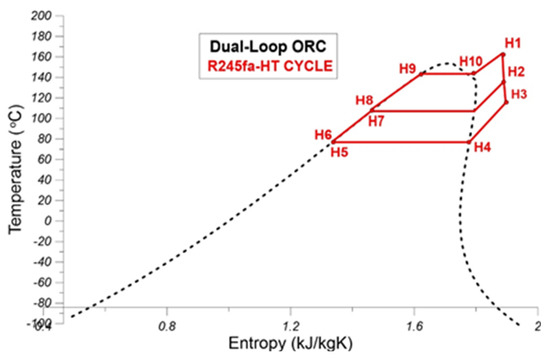
Figure 2.
Representation of thermodynamic processes of the high temperature (HT) loop of the regenerative dual-loop ORC with OFOH in a T-s diagram.
Figure 3 shows the thermodynamic processes that the organic fluid undergoes in the HT loop in a T-s diagram. In the LT loop, the subcooled organic fluid at state L8 enters the engine intercooler, where it recovers rejected heat from the charged air and it is heated under the constant evaporation pressure of the LT loop and it exits the intercooler as saturated organic liquid at state L9. Then the saturated organic liquid state L9 enters the preheater where it receives rejected heat from the condensed organic fluid of the HT loop and is converted to organic two-phase mixture, which exits the preheater at state L11. The two-phase mixture at state L11 enters the evaporator 2, where it receives the rejected heat from the engine coolant and it is heated under constant high evaporation pressure of the LT loop until it becomes saturated steam at state L1. The organic saturated steam state L1 enters the expander 2, where it expands up to intermediate pressure at state H2 and this state a portion of the superheated steam is extracted from the expander 2 and is transferred to the OFOH and the remaining organic mass flow rate continues to expand at low condensation pressure of the LT loop. The organic fluid exits the expander 2 as superheated steam at low condensation pressure at state L3. Subsequently, the superheated organic steam at state L3 enters the condenser of the LT loop, where the organic medium rejects heat to the seawater and exits the condenser as saturated organic liquid at state L5 and then it enters the circulation pump 1, where it compressed from the low condensation pressure to the intermediate pressure of the LT loop and exits the circulation pump 1 as subcooled organic liquid at state L6. The subcooled organic liquid state L6 enters the OFOH where is mixed with the superheated organic steam at state L2, which has been extracted from expander 2 at intermediate pressure and then the total organic mass flow rate exits the OFOH as saturated liquid state L7. Saturated liquid state L7 is compressed in the circulation pump 2 from the intermediate pressure to the high evaporation pressure of the LT loop and it exits the circulation pump 2 at state L8 as subcooled liquid to go again in the intercooler.
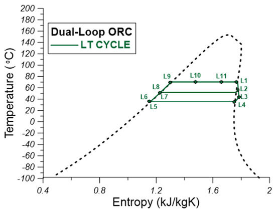
Figure 3.
Representation of thermodynamic processes of the low temperature (LT) loop of the regenerative dual-loop ORC with OFOH in a T-s diagram.
5. Energy and Exergy Analysis of the Regenerative Dual-Loop ORC
In the following section the energy and exergy analysis of the regenerative dual-loop ORC is described in detail. The corresponding energy and exergy analysis terms of the thermodynamic processes of the pertinent dual-loop ORC without the OFOH have been described in detail in Refs. [18,22], and they are not included in the present study for the sake of brevity of space.
5.1. Thermodynamic Processes of the HT Loop
The following thermodynamic processes take place in the HT loop of the regenerative dual-loop ORC, according to the Figure 2.
Process H1–H2–H3 (Expander 1): the generated power of the expander 1 of the HT loop taking into consideration both the expansion of the total flow rate of the superheated organic fluid from high evaporation pressure to intermediate pressure and the expansion of the remaining organic fluid flow rate after the extraction of a portion a from intermediate pressure to low condensation pressure of the HT loop is given in the following Equation (1). The isentropic efficiency of the expander 1 is given in Equation (2):
The mechanical generated power Pexp1 is converted to electrical power after multiplication with the efficiency of the electric generator, which is assumed to be equal to 99%.
The extraction rate α of the HT loop is defined, as follows:
The irreversibility rate of expander 1 is calculated, as follows:
Process H3–H5 (Preheater): The heat transfer rate from the organic medium of the HT loop to the preheater is given by the following relation:
The irreversibility rate of the organic medium in the preheater is calculated according to the following relation:
Process H5–H6 (Pump 1): The mechanical power consumption of the circulation pump 1 at the HT loop and the corresponding isentropic efficiency of the circulation pump 1 are given by the following relations:
The irreversibility rate of the circulation pump 1 is calculated from the following relation:
Process H2–H6–H7 (OFOH of the HT loop): the heat transfer rate from the hot organic stream that is extracted at the intermediate pressure of the HT loop is used to preheat the subcooled organic fluid state H6 that exits the circulation pump 1, according to the following relation:
The irreversibility rate of the organic fluid in the OFOH is calculated, as follows:
Process H7–H8 (Pump 2): The mechanical power consumption of the circulation pump 2 at the HT loop and its corresponding isentropic efficiency are calculated, as follows:
The irreversibility rate of the organic medium in the circulation pump 2 is given by the following relation:
Process H8–H1 (Evaporator 1): in the evaporator 1 of the HT loop exhaust gas heat is used for the heating of the organic fluid up from the subcooled to the superheated state, as described below:
The irreversibility rate of the evaporator 1 is calculated, as follows:
5.2. Thermodynamic Processes of the LT Loop
The organic medium undergoes the following thermodynamic processes in the LT loop in accordance with Figure 3.
Process L1–L2–L3 (Expander 2): the total power generated in the expander 2 comprised of the power generated from the total organic fluid mass flow rate that expands from the high evaporation pressure of the LT loop to its intermediate pressure and the power generated by the organic fluid flow rate that remains in expander 2 and it expands to the low condensation pressure of the LT loop after the extraction of portion “α” of total fluid flow rate at intermediate pressure. The total power generated in the expander 2 and the isentropic efficiency of expander 2 are given below:
The mechanical generated power Pexp2 is converted to electrical power after multiplication with the efficiency of the electric generator, which is assumed to be equal to 99%.
The portion “α” of organic fluid that is extracted from the LT loop expander and is transferred to the OFOH is:
The irreversibility rate of the organic fluid expansion in the expander 2 is given in the following relation:
Process L3–L5 (Condenser of the LT loop): the heat transfer losses of the organic medium in the condenser of the LT loop are transferred to the seawater and, thus, the energy balance in the LT loop condenser is:
where cp,sw is the isobaric heat capacity of the seawater, which is calculated as function of the temperature, salinity, and pressure, as follows:
where temperature “t” is given in Celsius, salinity “Skg/kg” is given in kg/kg, pressure p, and reference pressure p0 is given in MPa.
Equation (22) is valid for temperatures “t” [0,180 °C], salinities “Skg/kg” [0,0.18 kg/kg], and pressures “p” [0.1,1 MPa], according to Nayar et al. [29]. It is also valid for temperatures “t” [0,180 °C], salinity Skg/kg = 0 kg/kg, and pressures “p” [0,12 MPa]. Equation (22) is also valid for temperatures “t” [0,40 °C], salinities “Skg/kg” [0,0.042 kg/kg], and pressures “p” [0,12 MPa]. In the aforementioned regions of temperature, salinity, and pressure, the maximum uncertainty of Equation (22), according to Nayar et al. [29], is ± 1%.
The irreversibility rate of the condensation process in the LT loop is calculated, as follows:
where Tmc is the average condensation temperature of the working medium.
Process L5–L6 (Pump 1): the power consumption and the isentropic efficiency of circulation pump 1 are given by the following relations:
The irreversibility rate of the compression process in the circulation pump 1 is calculated, as follows:
Process L2–L6–L7 (OFOH of the LT loop): the heat transfer rate from the hot organic stream state L2 that is extracted at the intermediate pressure of the LT loop is used to preheat the subcooled organic fluid state L6 that exits the circulation pump 1, according to the following relation:
The irreversibility rate of the OFOH of the LT loop is calculated according to the following relation:
Process L7–L8 (Pump 2): the power consumption and the isentropic efficiency of the circulation pump 2 at the LT loop are calculated according to the following relations:
The irreversibility rate of the circulation pump 2 is estimated by the following relation:
Process L8–L9 (Intercooler): in the intercooler, the organic fluid harvests portion of the heat rejected by the engine charged air according to the following relation:
The irreversibility rate of the process that takes place in the intercooler of the LT loop is calculated, as follows:
Process L9–L11 (Preheater): in the preheater the organic medium of the LT loop receives a percentage of the heat that is rejected from the condensed organic medium of the HT loop. This percentage is determined by the effectiveness εpre of the preheater according to the following relation:
Process L11–L1 (Evaporator 2): in evaporator 2, the organic medium of the LT loop receives a percentage of the heat rejected by the engine coolant according to the effectiveness εeva2 of the evaporator 2, as described below:
The irreversibility rate of the evaporator 2 is calculated, as follows:
where Tme is the average evaporation temperature of the organic medium at evaporator 2.
5.3. Performance Indices of the Regenerative Dual-Loop ORC
The net generated power of the HT loop is the difference between the power generated in the expander 1 and the power consumed by the circulation pumps 1 and 2 of the HT loop:
The net generated power of the LT loop is the difference between the power generated in the expander 2 and the power consumed by the circulation pumps 1 and 2 of the LT loop:
Hence, the overall net generated power of the both the HT and LT loop is given by the following relation:
The thermal efficiency of the dual-loop ORC is given by the following relation:
where is the heat transfer rate of the evaporator 1 of the HT loop, is the heat transfer rate of the intercooler of the LT loop, and is the heat transfer rate between the engine coolant of the main diesel engine and the organic fluid in the evaporator 2 of the LT loop.
The main assumptions adopted for the examination of the regenerative dual-loop ORC are the following:
- The combined installation of the marine four-stroke diesel engine and the regenerative dual-loop ORC system operates under steady state conditions.
- Pressure drops in the pipelines are neglected.
- The isentropic efficiency of the expanders is 0.85.
- The isentropic efficiency of the circulation pumps is 0.75.
- The effectiveness of the LT loop intercooler was considered equal to 0.7, the effect of the preheater was considered equal to 0.5, and the effectiveness of the LT loop evaporator 2 was assumed equal to 0.5.
6. Modelling of the HT and LT Loop Heat Exchangers of the Regenerative ORC
Two different types of heat exchangers are considered in the present study having the waste heat transfer characteristics of the diesel engines in mind. A fin-and-tube heat exchanger is selected as evaporator 1 due to the high temperature of the exhaust gas, whereas a plate heat exchanger is used as intercooler, condenser, preheater, and evaporator 2. A heat transfer analysis for the fin-and-tube heat exchanger of the HT loop and the plate heat exchangers of the LT loop is essential in calculating the main dimensions, the heat transfer area, and the overall heat transfer coefficient of the heat exchangers and, then, in a following section, to calculate the capital cost of the heat exchangers based on their calculated heat transfer area. Heat exchanger analysis is also essential, since pure thermodynamics cannot provide the main dimensions, the heat transfer area, and the overall heat transfer coefficient of each heat exchanger. The calculation of area of heat exchanger is based on the logarithmic mean temperature difference (LMTD). According to this method, the heat transfer rate is:
6.1. Fin-and-Tube Heat Exchanger Thermal Analysis
The evaporator 1, which is considered to be a fin-and-tube heat exchanger is divided into three zones: the single-phase liquid zone (state H8–state H9), the two-phase zone (state H9–state H10), and the single-phase vapor zone (state H10–state H1), as observed from Figure 2. Figure 4 provides a schematic view of the fin-and-tube internal geometry.
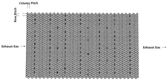
Figure 4.
Schematic view of the fin-and-tube heat exchanger.
The overall heat transfer coefficient in each section is given by the following relation:
The fouling resistance of organic fluid rin in the fin-and-tube heat exchanger was set equal to 0.0002, which corresponds to refrigerants liquids, as defined in Cao [30]. The fouling resistance of the external exhaust gas flow rout in the fin-and-tube heat exchanger was set equal to 0.002, which corresponds to diesel engine exhaust gases, as defined in Cao [30].
The Nusselt number for the exhaust gas is given by the Zukauskas correlation [31]:
When 1000 < Re:
when Re < 1000:
The Nusselt number for the single phase Nusselt number can be calculated using the Gnielinski correlation [32]:
where:
In the single-phase liquid zone [18]:
In the single-phase vapor zone [18]:
The wall temperature at the external exhaust gas flow is calculated from the following relation [30]:
The wall temperature of the internal organic fluid flow is calculated, as follows [30]:
For the liquid and the vapor phase zone inside the tube, the heat exchanger is divided into N parts according to the progressive variation of the vapor quality. The thermodynamic properties in each part can be considered as constant. The convective heat transfer coefficient is given by the Liu and Winterton correlation [33]:
The forced convective heat transfer enhancement factor can be determined, as follows [18]:
The suppression factor is [18]:
The film boiling convective heat transfer coefficient can be calculated using Dittus–Boelter correlation [18]:
The convective heat transfer coefficient for the nucleate boiling is given by the Cooper’s pool boiling correlation [18]:
6.2. Plate Heat Exchanger Thermal Analysis
Figure 5 provides a representative schematic view of the plate heat exchanger.
Figure 5.
Representative schematic view of the plate heat exchanger.
The overall heat transfer coefficient of the plate heat exchanger can be calculated, as follows:
The fouling resistance of internal organic fluid flow rin in all plate heat exchangers was set equal to 0.0002, as dictated by Cao [30]. The fouling resistance of external air flow rout in the plate heat exchanger of intercooler was set equal to 0.0002 [30]. The fouling resistance of the external engine coolant flow rout in the LT loop evaporator was set equal to 0.0002 [30] and the external organic fluid flow rout of the HT loop in the plate heat exchanger of the preheater was also set equal to 0.0002 [30]. The fouling resistance of the external seawater flow in the LT loop condenser was set equal to 0.00009 [30].
The Nusselt number for the single-phase working fluid can be calculated from the Chisholm and Wanniarachchi [18,34]:
The Reynolds number is given from the following relation [18]:
The mass flux can be expressed, as follows [18]:
The hydraulic diameter of the flow channel can be calculated, as follows [18]:
The two-phase heat transfer zone of the plate heat exchanger is divided into N parts according to the variation of vapor quality in the two-phase region. The Nusselt number for the condensation process is [35]:
The Nusselt number for the evaporation process can be determined from the following relation [36]:
The equivalent Reynolds number can be calculated, as follows [18]:
The equivalent boiling number can be expressed as [18]:
where:
7. Exhaust Gas Pressure Drop at the HT Loop Evaporator 1
The calculation of the exhaust gas pressure drop at the HT loop evaporator is that the highest portion of diesel engine exhaust gases is air since marine diesel engines always operate with excess air and with a high air to fuel ratio, which is considerably higher than the stoichiometric. Hence, according to Cao [30], the pressure drop of the air through heat exchanger bundle of tubes is:
where f is the friction factor and GS is the mass flow density, which is defined as [30]:
Additionally, Lp is the length of path, which is defined as [30]:
The geometrical parameters SL, ST and SF are defined in the following Figure 6. In Equation (66), parameter De’ is the equivalent diameter for friction and it is defined, as follows [30]:
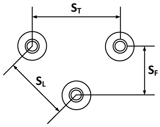
Figure 6.
Graphical representation of the geometrical dimensions ST, SL, and SF of the heat exchanger tubes [30].
The net free volume is the volume between the central plates of two consecutive rows minus the portion of that volume occupied by the tubes and fins [30]:
The friction factor f can be expressed as function of the Reynolds number, as follows [30]:
where the Reynolds number Re’S is defined, as follows:
8. Economic Analysis—Calculation of the Total Capital Cost and Electricity Production Cost
The dual-loop ORC is comprised from many different components. All direct and overhead costs should be taken into consideration for each part of the installation. The Module Costing Technique (MCT) is a commonly used method for calculating the bare module cost of chemical plants [37]. Based on the MCT, the capital cost of the heat exchanger can be calculated while using the following relation:
where the Chemical Engineering Plant Cost Index (CEPCI) is used for adjusting the specific installation cost for different years. CEPCI2019 and CEPCI2001 is the Chemical Engineering Plant Cost Index for years 2001 and 2019, respectively, CHX0 is the bare module cost of the heat exchanger, FS is the construction overhead cost factor, B1,HX and B2,HX are the constants that depend on the heat exchanger type, and FM,HX and FP,HX are the material and pressure factors, respectively. The value of CEPCI2019 and CEPCI2001 are 607.5 and 397, respectively [26], the value of Fs is 1.70, the values of B1,HX and B2,HX are 0.96 and 1.21, respectively, and the value of FM,JX is 2.40 [36].
The bare module cost of the heat exchanger is:
where K1,HX, K2,HX, and K3,HX are the constants that depend from heat exchanger type and AHX is the heat exchanger area. The values of K1,HX, K2,HX, and K3,HX are 4.66, −0.1557, and 0.1547, respectively [36].
The pressure factor of the heat exchanger is [37]:
where C1,HX, C2,HX, and C3,HX are the constants that depend on the type of heat exchanger and PHX is the design pressure of the heat exchanger. The values of C1,HX, C2,HX, and C3,HX are all zero.
The capital cost of the circulation pump is [37]:
where CPP0 is the bare module cost of the circulation pump, B1,PP and B2,PP are the constants that depend from the type of the circulation pump, and FM,PP and FP,PP are the material and pressure factors, respectively. The values of B1,PP and B2,PP are 1.89 and 1.35, respectively, and the value of FM,PP is 2.20 [36].
The bare module cost of the circulation pump is [37]:
where K1,PP, K2,PP, and K3,PP are the constants that depend from the type of the circulation pump and is the power consumption of the circulation pump. The values of K1,PP, K2,PP, and K3,PP are 3.389, 0.536, and 0.1538, respectively [36].
The pressure factor of the circulation pump can be determined, as follows:
where C1,PP, C2,PP, and C3,PP are the constants that depend on the type of the circulation pump and PPP is the design pressure of the circulation pump. The values of C1,PP, C2,PP, and C3,PP are −0.3935, 0.3957, and −0.00226, respectively [36].
The capital cost of the expander can be expressed, as follows:
where is the bare module cost of the expander and FMP is the additional expander factor, which is equal to 3.5 [36].
The bare module cost of the expander is:
where K1,EXP, K2,EXP, and K3,EXP are the constants that depend on the type of the expander, and is the power output of the expander. The values of K1,EXP, K2,EXP, and K3,EXP are 2.2659, 1.4398, and −0.1776, respectively [36].
According to Imran et al. [28], the cost of the feed heater is:
where B1,FH and B2,FH are constants for feed heater type, which are equal to 1.12 and 0.87, respectively, and FM,PH is the additional material factor, FP,PH is the pressure factor for the OFOH, and C’FH is the basic cost of the OFOH.
The basic cost of the OFOH is [28]:
where K1,FH, K2,FH, and K3,FH are the constants for the OFOH type, which are equal to 4.2, −0.204, and 0.1245, respectively. The pressure factor of the OFOH is [28]:
where the constant C1,FH is equal to 0.0, constant C2,FH is equal to 10, and constant C3,FH is equal to 0.0.
The total investment cost (TIC) of the system is the sum of the capital cost of each component of the installation:
The Capital Recovery Factor (CRF) is [38]:
where i is the interest rate and LTpl is the plant lifetime. The value of interest rate i is 0.1 and the value of LTpl is 15 [36].
The Electricity Production Cost (EPC) is:
where fk is the maintenance and insurance cost factor, which is equal to 0.0165 [35] and hfull_load is the full load operation hours, which is 4000.
9. Results and Discussion
9.1. Parametric Investigation to Determine the Optimum Regenerative Dual-Loop ORC and the Optimum Organic Fluids for the HT and LT Loops
In this section, a parametric study is performed for examining the effect of various combinations of the organic fluids examined in the present study under different thermodynamic parameters on the thermodynamic performance and cost indices of the regenerative dual-loop ORC. The purpose of this parametric investigation is the determination of the optimum pair of organic fluids for the HT and the LT loop of the regenerative ORC and the specification of the optimum settings of the HT and the LT loop of the regenerative dual-loop ORC. The examination of the effect of all combinations of organic fluids is performed at the MCR of the examined main diesel engine. The combinations of organic mediums that are examined in this parametric study are the following:
- HT loop: R245fa + LT loop: R245fa
- HT loop: R245fa + LT loop: R1234yf
- HT loop: R245fa + LT loop: R1234ze
- HT loop: R600 + LT loop: R600
- HT loop: R600 + LT loop: R1234yf
- HT loop: R600 + LT loop: R1234ze
For each one of the previously mentioned pairs of organic mediums, it is examined the effect of the following thermodynamic parameters on the total generated electric power, the thermal cycle efficiency, the total irreversibility rate, the total investment cost, and the cost of generated electrical energy:
- Evaporation pressure of the HT loop.
- Superheating degree of the organic medium in the HT loop.
- Condensation temperature of the HT loop.
- Evaporation temperature of the LT loop.
- Condensation temperature of the LT loop.
- Exhaust gas temperature after the evaporator of the HT loop.
9.1.1. Effect of the Evaporation Pressure of the HT Loop
In this section, the effect of HT loop evaporation pressure on the generated power and the thermal efficiency of the regenerative dual-loop ORC, on the total irreversibility rate of the regenerative dual-loop ORC, on the total investment cost, and on the electricity production cost (EPC) is examined for all the pairs of organic fluids considered in this study. The variation of generated power of the regenerative dual-loop ORC with HT loop evaporation pressure for all of the combinations of organic mediums considered in this study is shown in Figure 7a. As observed, the increase of HT loop evaporation pressure results, as expected, in the increase of the generated power at all cases of organic fluid pairs. The highest values of generated power are observed for the organic medium pair R245fa (HT loop) and R245fa (LT loop), whereas the lowest values of generated power are evidenced for the organic medium pair R600 (HT loop) and R1234yf (LT loop).
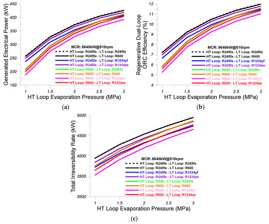
Figure 7.
(a) Effect of evaporation pressure of the HT loop on the generated electric power of the regenerative dual-loop ORC; (b) Effect of evaporation pressure of the HT loop on the thermal efficiency of the regenerative dual-loop ORC; (c) Effect of evaporation pressure of the HT loop on the total irreversibility rate of the regenerative dual-loop ORC. Results are given for all the pairs of organic mediums that are examined in the present study.
Figure 7b shows the variation of the regenerative dual-loop ORC thermal efficiency with HT loop evaporation pressure for all organic medium combinations considered in this study. As witnessed, the thermal efficiency of the regenerative dual-loop ORC increases with increasing HT loop evaporation pressure due to the corresponding of the generated electrical power for the same waste heat transfer rates from the main diesel engine. The highest values of thermal efficiency are observed for the organic medium pair R245fa (HT loop) and R245fa (LT loop), whereas the lowest values of thermal efficiency are evidenced for the organic medium pair R600 (HT loop) and R1234yf (LT loop).
Figure 7c shows the variation of the total irreversibility rate of the regenerative dual-loop ORC with HT loop evaporation pressure for all organic fluid pairs considered in the present analysis. As observed, the increase of the HT loop evaporation pressure results in an increase of the total irreversibility rate of the regenerative dual-loop mainly due to the increase of irreversibility rates in the HT loop expander, which was the result of the increase of its pressure ratio. The highest values of total irreversibility rate are observed for the organic medium pairs R245fa (HT loop) and R600 (LT loop) and R245fa (HT loop) and R245fa (LT loop), whereas the lowest values of total irreversibility rate are evidenced for the organic medium pair R600 (HT loop) and R1234yf (LT loop).
Figure 8a shows the variation of the total investment cost with the HT loop evaporation pressure for all organic fluid pairs considered in the present study. The increase of the HT loop evaporation pressure results in the increase of the total investment cost of the regenerative dual-loop ORC installation, as witnessed from Figure 8a. The highest values of total investment cost are observed for the organic medium pair R245fa (HT loop) and R245fa (LT loop), whereas the lowest values of total investment cost are evidenced for the two organic medium pairs R600 (HT loop) and R1234ze (LT loop) and R600 (HT loop) and R1234yf (LT loop).
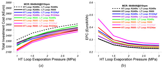
Figure 8.
(a) Effect of evaporation pressure of the HT loop on the total investment cost of the regenerative dual-loop ORC; (b) Effect of evaporation pressure of the HT loop on the electricity production cost (EPC) of the regenerative dual-loop ORC. The results are given for all the pairs of organic mediums that are examined in the present study.
Figure 8b shows the variation of the EPC with the HT loop evaporation rate for all organic medium pairs considered in the present analysis. The cost of the produced electricity is reduced at all cases of organic medium pairs with increasing HT loop evaporation pressure. The highest values of EPC are observed for the organic medium pair R600 (HT loop) and R1234yf (LT loop), whereas the lowest values of EPC are evidenced for the two organic medium pairs R245fa (HT loop) and R245fa (LT loop) and R245fa (HT loop) and R600 (LT loop).
9.1.2. Effect of the Superheating Degree of the Organic Medium in the HT Loop
In this section, the influence of HT loop superheating degree on the generated power and the thermal efficiency of the regenerative dual-loop ORC, on the total irreversibility rate of the regenerative dual-loop ORC, on the total investment cost, and on the electrical power cost (EPC) is examined for all the pairs of organic fluids considered in this study.
The variation of generated power of the regenerative dual-loop ORC with HT loop superheating degree for all the combinations of organic mediums considered in this study is shown in Figure 9a. As observed, the increase of HT loop superheating degree does not provide noticeable change of the generated power in all cases of organic fluid pairs. The highest values of generated power are observed for the organic medium pair R245fa (HT loop) and R245fa (LT loop), whereas the lowest values of generated power are evidenced for the organic medium pair R600 (HT loop) and R1234yf (LT loop).
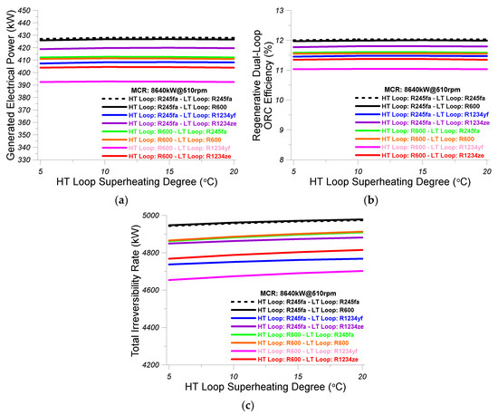
Figure 9.
(a) Effect of the superheating degree of the organic medium in the HT loop on the generated electric power of the regenerative dual-loop ORC; (b) Effect of the superheating degree of the organic medium in the HT loop on the thermal efficiency of the regenerative dual-loop ORC; (c) Effect of the superheating degree of the organic medium in the HT loop on the total irreversibility rate of the regenerative dual-loop ORC. Results are given for all of the pairs of organic mediums that are examined in the present study.
The variation of thermal efficiency of the regenerative dual-loop ORC with HT loop superheating degree for all of the combinations of organic mediums considered in this study is shown in Figure 9b. As observed, the increase of HT loop superheating degree does not provide noticeable change of the thermal efficiency at all cases of organic fluid pairs. The highest values of the thermal efficiency of the regenerative dual-loop ORC are observed for the organic medium pair R245fa (HT loop) and R245fa (LT loop), whereas the lowest values of generated power are evidenced for the organic medium pair R600 (HT loop) and R1234yf (LT loop).
Figure 9c shows the variation of the total irreversibility rate of the regenerative dual-loop ORC with HT loop superheating degree for all the combinations of organic mediums considered in this study. As observed, the increase of HT loop superheating degree results in a small increase of the total irreversibility rate at all cases of organic fluid pairs. The highest values of the total irreversibility rate of the regenerative dual-loop ORC are observed for the organic medium pairs R245fa (HT loop) and R245fa (LT loop) and R245fa (HT loop) and R600 (LT loop), whereas the lowest values of the total irreversibility rate are evidenced for the organic medium pair R600 (HT loop) and R1234yf (LT loop).
Figure 10a shows the variation of the total investment cost with the HT loop superheating degree for all of organic fluid pairs considered in the present study. The increase of the HT loop superheating degree results in small increase of the total investment cost of the regenerative dual-loop ORC installation, as witnessed from Figure 10a. The highest values of total investment cost are observed for the organic medium pair R245fa (HT loop) and R245fa (LT loop), whereas the lowest values of total investment cost are evidenced for the organic medium pair R600 (HT loop) and R1234yf (LT loop).
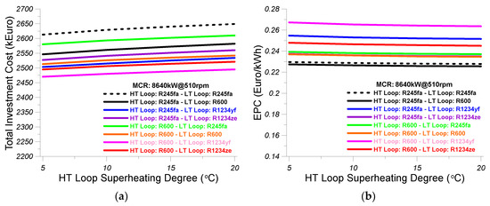
Figure 10.
(a) Effect of the superheating degree of the organic medium in the HT loop on the total investment cost of the regenerative dual-loop ORC; (b) Effect of the superheating degree of the organic medium in the HT loop on the electricity production cost (EPC) of the regenerative dual-loop ORC. Results are given for all the pairs of organic mediums that are examined in the present study.
Figure 10b shows the variation of the EPC with the HT loop superheating degree for all organic medium pairs considered in the present analysis. The cost of the produced electricity is slightly reduced at all cases of organic medium pairs with increasing HT loop superheating degree. The highest values of EPC are observed for the organic medium pair R600 (HT loop) and R1234yf (LT loop), whereas the lowest values of EPC are evidenced for the two organic medium pairs R245fa (HT loop) and R245fa (LT loop) and R245fa (HT loop) and R600 (LT loop).
9.1.3. Effect of the Condensation Temperature of the HT Loop
In this section the influence of HT loop condensation temperature on the generated power and the thermal efficiency of the regenerative dual-loop ORC, on the total irreversibility rate of the regenerative dual-loop ORC, on the total investment cost, and on the electrical power cost (EPC) is examined for all the pairs of organic fluids considered in this study.
The variation of generated power of the regenerative dual-loop ORC with HT loop condensation temperature for all of the combinations of organic mediums considered in this study is shown in Figure 11a. As observed, the increase of HT loop condensation temperature results in a reduction of the generated power at all cases of organic fluid pairs due to the reduction of the pressure ratio in the HT loop expander. The highest values of generated power are observed for the organic medium pair R245fa (HT loop) and R245fa (LT loop), whereas the lowest values of generated power are evidenced for the organic medium pair R600 (HT loop) and R1234yf (LT loop).
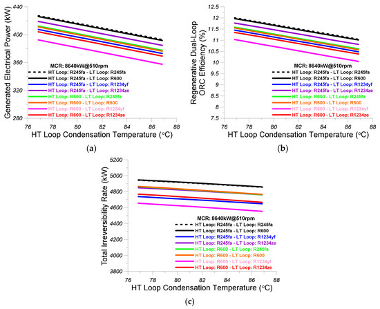
Figure 11.
(a) Effect of the condensation temperature of the HT loop on the generated electric power of the regenerative dual-loop ORC; (b) Effect of the condensation temperature of the HT loop on the thermal efficiency of the regenerative dual-loop ORC; (c) Effect of the condensation temperature of the HT loop on the total irreversibility rate of the regenerative dual-loop ORC. Results are given for all the pairs of organic mediums that are examined in the present study.
The variation of thermal efficiency of the regenerative dual-loop ORC with HT loop condensation temperature for all of the combinations of organic mediums considered in this study is shown in Figure 11b. As observed, the increase of HT loop condensation temperature results in a linear reduction of the thermal efficiency at all cases of organic fluid pairs. The highest values of the thermal efficiency of the regenerative dual-loop ORC are observed for the organic medium pair R245fa (HT loop) and R245fa (LT loop), whereas the lowest values of generated power are evidenced for the organic medium pair R600 (HT loop) and R1234yf (LT loop).
Figure 11c shows the variation of the total irreversibility rate of the regenerative dual-loop ORC with HT loop condensation temperature for all the combinations of organic mediums considered in this study. As observed, the increase of HT loop condensation temperature results in a reduction of the total irreversibility rate at all cases of organic fluid pairs. The highest values of the total irreversibility rate of the regenerative dual-loop ORC are observed for the organic medium pairs R245fa (HT loop) and R245fa (LT loop) and R245fa (HT loop) and R600 (LT loop), whereas the lowest values of the total irreversibility rate are evidenced for the organic medium pair R600 (HT loop) and R1234yf (LT loop).
Figure 12a shows the variation of the total investment cost with the HT loop condensation temperature for all organic fluid pairs considered in the present study. The increase of the HT loop condensation temperature results in the reduction of the total investment cost of the regenerative dual-loop ORC installation, as witnessed from Figure 12a. The highest values of total investment cost are observed for the organic medium pair R245fa (HT loop) and R245fa (LT loop), whereas the lowest values of total investment cost are evidenced for the two organic medium pairs R600 (HT loop) and R600 (LT loop) and R600 (HT loop) and R1234ze (LT loop).
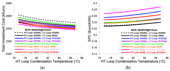
Figure 12.
(a) Effect of the condensation temperature of the HT loop on the total investment cost of the regenerative dual-loop ORC; (b) Effect of the condensation temperature of the HT loop on the electricity production cost (EPC) of the regenerative dual-loop ORC. The results are given for all the pairs of organic mediums that are examined in the present study.
The variation of the EPC with the HT loop condensation temperature for all organic medium pairs considered in the present analysis is shown in Figure 12b. The cost of the produced electricity is increased at all cases of organic medium pairs with increasing HT loop condensation temperature. The highest values of EPC are observed for the organic medium pair R600 (HT loop) and R1234yf (LT loop), whereas the lowest values of EPC are evidenced for the two organic medium pairs R245fa (HT loop) and R245fa (LT loop) and R245fa (HT loop) and R600 (LT loop).
9.1.4. Effect of the Evaporation Temperature of the LT Loop
In this section, the influence of the LT loop evaporation temperature on the generated power and the thermal efficiency of the regenerative dual-loop ORC, on the total irreversibility rate of the regenerative dual-loop ORC, on the total investment cost, and on the electrical power cost (EPC) is examined for all the pairs of organic fluids considered in this study.
The variation of generated power of the regenerative dual-loop ORC with the LT loop evaporation temperature for all of the combinations of organic mediums considered in this study is shown in Figure 13a. As observed, the increase of LT loop evaporation temperature results in the linear increase of the generated power at all cases of organic fluid pairs due to the increase of the pressure ratio in the LT loop expander. The highest values of generated power are observed for the organic medium pair R245fa (HT loop) and R245fa (LT loop), whereas the lowest values of generated power are evidenced for the organic medium pair R600 (HT loop) and R1234yf (LT loop).
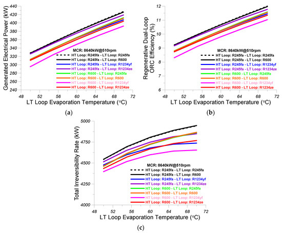
Figure 13.
(a) Effect of the evaporation temperature of the LT loop on the generated electric power of the regenerative dual-loop ORC; (b) Effect of the evaporation temperature of the LT loop on the thermal efficiency of the regenerative dual-loop ORC; (c) Effect of the evaporation temperature of the LT loop on the total irreversibility rate of the regenerative dual-loop ORC. Results are given for all the pairs of organic mediums that are examined in the present study.
Figure 13b shows the variation of thermal efficiency of the regenerative dual-loop ORC with LT loop evaporation temperature for all combinations of organic mediums considered in this study. As observed, the increase of LT loop evaporation temperature results in a linear increase of the thermal efficiency at all cases of organic fluid pairs. The highest values of the thermal efficiency of the regenerative dual-loop ORC are observed for the organic medium pair R245fa (HT loop) and R245fa (LT loop), whereas the lowest values of generated power are evidenced for the organic medium pair R600 (HT loop) and R1234yf (LT loop).
Figure 13c shows the variation of the total irreversibility rate of the regenerative dual-loop ORC with LT loop evaporation temperature for all of the combinations of organic mediums considered in this study. As observed, the increase of LT loop evaporation temperature results in the increase of the total irreversibility rate at all cases of organic fluid pairs. The highest values of the total irreversibility rate of the regenerative dual-loop ORC are observed for the organic medium pairs R245fa (HT loop) and R245fa (LT loop) and R245fa (HT loop) and R600 (LT loop), whereas the lowest values of the total irreversibility rate are evidenced for the organic medium pair R600 (HT loop) and R1234yf (LT loop).
Figure 14a shows the variation of the total investment cost with the LT loop evaporation temperature for all organic fluid pairs considered in the present study. The increase of the LT loop evaporation temperature results in the increase of the total investment cost of the regenerative dual-loop ORC installation, as witnessed from Figure 14a. The highest values of total investment cost are observed for the organic medium pair R245fa (HT loop) and R245fa (LT loop), whereas the lowest values of total investment cost are evidenced for the two organic medium pairs R600 (HT loop) and R600 (LT loop) and R600 (HT loop) and R1234ze (LT loop).
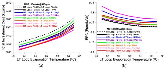
Figure 14.
(a) Effect of the evaporation temperature of the LT loop on the total investment cost of the regenerative dual-loop ORC; (b) Effect of the evaporation temperature of the LT loop on the electricity production cost (EPC) of the regenerative dual-loop ORC. Results are given for all the pairs of organic mediums that are examined in the present study.
Figure 14b shows the variation of the EPC with the LT loop evaporation temperature for all organic medium pairs considered in the present analysis. The cost of the produced electricity is decreased at all cases of organic medium pairs with increasing LT loop evaporation temperature. The highest values of EPC are observed for the organic medium pair R600 (HT loop) and R1234yf (LT loop), whereas the lowest values of EPC are evidenced for the two organic medium pairs R245fa (HT loop) and R245fa (LT loop) and R245fa (HT loop) and R600 (LT loop).
9.1.5. Effect of the Condensation Temperature of the LT Loop
In this section, the influence of the LT loop condensation temperature on the generated power and the thermal efficiency of the regenerative dual-loop ORC, on the total irreversibility rate of the regenerative dual-loop ORC, on the total investment cost, and on the electrical power cost (EPC) is examined for all of the pairs of organic fluids considered in this study.
The variation of generated power of the regenerative dual-loop ORC with the LT loop condensation temperature for all combinations of organic mediums considered in this study is shown in Figure 15a. As observed, the increase of LT loop condensation temperature results in the linear reduction of the generated power at all cases of organic fluid pairs due to the reduction of the pressure ratio in the LT loop expander. The highest values of generated power are observed for the organic medium pair R245fa (HT loop) and R245fa (LT loop), whereas the lowest values of generated power are evidenced for the organic medium pair R600 (HT loop) and R1234yf (LT loop).
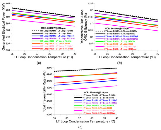
Figure 15.
(a) Effect of the condensation temperature of the LT loop on the generated electric power of the regenerative dual-loop ORC; (b) Effect of the condensation temperature of the LT loop on the thermal efficiency; (c) Effect of the condensation temperature of the LT loop on the total irreversibility rate of the regenerative dual-loop ORC. Results are given for all the pairs of organic mediums that are examined in the present study.
Figure 15b shows the variation of thermal efficiency of the regenerative dual-loop ORC with LT loop condensation temperature for all combinations of organic mediums considered in this study. As observed, the increase of LT loop condensation temperature results in a linear reduction of the thermal efficiency at all cases of organic fluid pairs. The highest values of the thermal efficiency of the regenerative dual-loop ORC are observed for the organic medium pair R245fa (HT loop) and R245fa (LT loop), whereas the lowest values of generated power are evidenced for the organic medium pair R600 (HT loop) and R1234yf (LT loop).
Figure 15c shows the variation of the total irreversibility rate of the regenerative dual-loop ORC with LT loop condensation temperature for all combinations of organic mediums considered in this study. As observed, the increase of LT loop condensation temperature results in the increase of the total irreversibility rate at all cases of organic fluid pairs. The highest values of the total irreversibility rate of the regenerative dual-loop ORC are observed for the organic medium pairs R245fa (HT loop) and R245fa (LT loop) and R245fa (HT loop) and R600 (LT loop), whereas the lowest values of the total irreversibility rate are evidenced for the organic medium pair R600 (HT loop) and R1234yf (LT loop).
Figure 16a shows the variation of the total investment cost with the LT loop condensation temperature for all organic fluid pairs considered in the present study. The increase of the LT loop condensation temperature results in reduction of the total investment cost of the regenerative dual-loop ORC installation, as witnessed from Figure 16a. The highest values of total investment cost are observed for the organic medium pair R245fa (HT loop) and R245fa (LT loop), whereas the lowest values of total investment cost are evidenced for the organic medium pair R600 (HT loop) and R1234yf (LT loop).
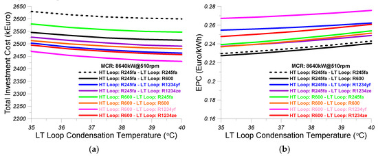
Figure 16.
(a) Effect of the condensation temperature of the LT loop on the total investment cost of the regenerative dual-loop ORC; (b) Effect of the condensation temperature of the LT loop on the electricity production cost (EPC) of the regenerative dual-loop ORC. Results are given for all the pairs of organic mediums that are examined in the present study.
Figure 16b shows the variation of the EPC with the LT loop condensation temperature for all organic medium pairs considered in the present analysis. The cost of the produced electricity increases at all cases of organic medium pairs with increasing LT loop evaporation temperature. The highest values of EPC are observed for the organic medium pair R600 (HT loop) and R1234yf (LT loop), whereas the lowest values of EPC are evidenced for the two organic medium pairs R245fa (HT loop) and R245fa (LT loop) and R245fa (HT loop) and R600 (LT loop).
9.1.6. Effect of the Exhaust Gas Temperature After the Evaporator of the HT Loop
In this section, the influence of the exhaust gas temperature at HT loop evaporator 1 outlet on the generated power and the thermal efficiency of the regenerative dual-loop ORC, on the total irreversibility rate of the regenerative dual-loop ORC, on the total investment cost, and on the electrical power cost (EPC) is examined for all of the pairs of organic fluids considered in this study.
Figure 17a shows the variation of generated power of the regenerative dual-loop ORC with the exhaust gas temperature at HT loop evaporator 1 outlet for all of the combinations of organic mediums considered in this study. As observed, the increase of exhaust gas temperature results in the linear reduction of the generated power at all cases of organic fluid pairs due to the reduction of the exhaust gas heat transferred to the organic fluid at the HT loop evaporator 1. The highest values of generated power are observed for the organic medium pair R245fa (HT loop) and R245fa (LT loop), whereas the lowest values of generated power are evidenced for the organic medium pair R600 (HT loop) and R1234yf (LT loop).
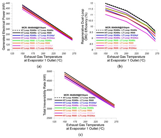
Figure 17.
(a) Effect of the exhaust gas temperature after the evaporator 1 of the HT loop on the generated electric power of the regenerative dual-loop ORC; (b) Effect of the exhaust gas temperature after the evaporator 1 of the HT loop on the thermal efficiency of the regenerative dual-loop ORC; (c) Effect of the exhaust gas temperature after the evaporator 1 of the HT loop on the total irreversibility rate of the regenerative dual-loop ORC. Results are given for all the pairs of organic mediums that are examined in the present study.
Figure 17b shows the variation of thermal efficiency of the regenerative dual-loop ORC with the exhaust gas temperature at HT loop evaporator 1 outlet for all combinations of organic mediums considered in this study. As observed, the increase of the exhaust gas temperature at HT loop evaporator 1 outlet results in reduction of the thermal efficiency at all cases of organic fluid pairs. The highest values of the thermal efficiency of the regenerative dual-loop ORC are observed for the organic medium pair R245fa (HT loop) and R245fa (LT loop), whereas the lowest values of generated power are evidenced for the organic medium pair R600 (HT loop) and R1234yf (LT loop).
Figure 17c shows the variation of the total irreversibility rate of the regenerative dual-loop ORC with the exhaust gas temperature at HT loop evaporator 1 outlet for all combinations of organic mediums considered in this study. As observed, the increase of the exhaust gas temperature at HT loop evaporator 1 outlet results in the linear reduction of the total irreversibility rate at all cases of organic fluid pairs. The highest values of the total irreversibility rate of the regenerative dual-loop ORC are observed for the organic medium pairs R245fa (HT loop) and R245fa (LT loop) and R245fa (HT loop) and R600 (LT loop), whereas the lowest values of the total irreversibility rate are evidenced for the organic medium pair R600 (HT loop) and R1234yf (LT loop).
Figure 18a shows the variation of the total investment cost with the exhaust gas temperature at HT loop evaporator 1 outlet for all organic fluid pairs considered in the present study. The increase of the exhaust gas temperature at HT loop evaporator 1 outlet results in the reduction of the total investment cost of the regenerative dual-loop ORC installation, as witnessed from Figure 18a. The highest values of total investment cost are observed for the organic medium pair R245fa (HT loop) and R245fa (LT loop), whereas the lowest values of total investment cost are evidenced for the organic medium pairs R600 (HT loop) and R1234yf (LT loop) and R600 (HT loop) and R1234ze (LT loop). However, it should be noted that the variation of the total investment cost between all organic fluid pairs are not significant and, thus, the deviation between the highest and lowest values are not considerable.
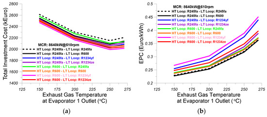
Figure 18.
(a) Effect of the exhaust gas temperature after the evaporator 1 of the HT loop on the total investment cost of the regenerative dual-loop ORC; (b) Effect of the exhaust gas temperature after the evaporator 1 of the HT loop on the electricity production cost (EPC) of the regenerative dual-loop ORC. Results are given for all the pairs of organic mediums that are examined in the present study.
Figure 18b shows the variation of the EPC with the exhaust gas temperature at HT loop evaporator 1 outlet for all organic medium pairs considered in the present analysis. The cost of the produced electricity increases at all cases of organic medium pairs with increasing exhaust gas temperature at HT loop evaporator 1 outlet. The highest values of EPC are observed for the organic medium pair R600 (HT loop) and R1234yf (LT loop), whereas the lowest values of EPC are evidenced for the two organic medium pairs R245fa (HT loop) and R245fa (LT loop) and R245fa (HT loop) and R600 (LT loop).
Hence, from the parametric investigation performed regarding the effect of various thermodynamic parameters and pairs of organic mediums on the performance characteristics and the cost parameters of the regenerative dual-loop ORC, it can be concluded that the optimum dual-loop ORC with OFOH should operate with the following organic fluids and it should have the following settings:
- The optimum organic fluid of the HT loop is R245fa and the optimum organic fluid of the LT loop is R600. This is the best organic fluid pair solution compared to all others examined, because it provides the maximum electrical power with the lowest cost per kWh and it also provides the highest thermal efficiency despite the fact that it does not provide the lowest total investment cost and it has the highest total irreversibility rate.
- The optimum superheating degree of the HT loop is 20 °C.
- The minimum and, thus, optimum condensation temperature of the HT cycle was found to be equal to 76.85 °C. The maximum and, thus, optimum evaporation temperature of the LT cycle was found to be equal to 70 °C and the minimum and, thus, optimum condensation temperature of the LT cycle was found to be equal to 35 °C. The condensation temperature of the LT cycle was selected based on the fact that the condenser of the LT cycle will be cooled with seawater. The seawater temperature does not exceed over 27 °C, according to the historic data of average monthly seawater surface temperature of Greek seas from 1850 to 2006 [39]. Hence, the minimum and, thus, optimum LT loop condensation temperature of 35 °C is 8 °C higher when compared to the highest possible inlet seawater temperature at the LT loop condenser and, thus, it satisfies the heat transfer ability from the organic fluid to the seawater
- The lowest temperature of the exhaust gas at the exit of evaporator 1 of the HT cycle is set to 150 °C in order to be 30 °C higher than the dew point temperature of exhaust gas in case the fuel burned in the engine contains sulphur [5].
9.2. Comparative Evaluation of the Simple Dual-Loop ORC with the Regenerative Dual-Loop ORC
This section comparatively evaluates the main thermal performance parameters of the simple dual-loop ORC without OFOH and the regenerative dual-loop ORC with OFOH. Figure 19a presents the comparatively evaluated variation of generated electrical power of the simple dual-loop ORC and the regenerative dual-loop ORC with engine load. As observed, the generated electrical power increases with engine load and it is higher in the case of the regenerative dual-loop ORC when compared to simple dual-loop ORC for all engine loads. The difference in generated power between the two examined cycles is progressively increasing with increasing load. The generated power of the regenerative dual-loop ORC varies from 156.5 kW at 40% of MCR to almost 636 kW at 100% of MCR. Figure 19b presents the comparatively assessed variation of the bsfc improvement of the simple dual-loop ORC and the regenerative dual-loop ORC with engine load. As observed, the bsfc improvement increases with engine load and the values of bsfc improvement of the regenerative dual-loop ORC are higher as compared to the corresponding values of the simple dual-loop ORC at all engine loads, because, as evidenced in Figure 19a, the regenerative dual-loop ORC generates more power when compared to the simple dual-loop ORC at all engine loads. Specifically, the bsfc improvement of the regenerative dual-loop ORC varies from 3.3% at 40% of MCR to 6.7% at 100% of MCR. Overall, it can be concluded that the regenerative dual-loop ORC generates more power and it results in higher bsfc improvement when compared to the simple dual-loop ORC at all cases of engine load examined.
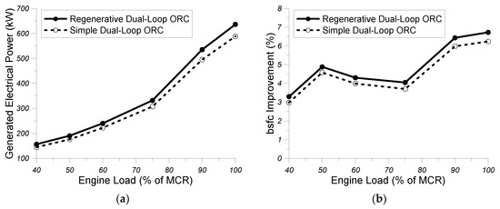
Figure 19.
Comparison of (a) generated electric power and (b) bsfc improvement between the simple dual-loop ORC and the regenerative dual-loop ORC.
Figure 20a illustrates the comparatively evaluated variation of the cycle thermal efficiency of the simple dual-loop ORC and the regenerative dual-loop ORC with engine load. As evidenced, the variation of thermal efficiency with engine load is limited for both examined bottoming cycles. Additionally, the values of thermal efficiency for the regenerative dual-loop ORC are higher when compared to the corresponding values of the simple dual-loop ORC at all engine loads examined. Specifically, the thermal efficiency of the regenerative dual-loop ORC ranges from 12.5% at 40% of MCR to 12.3% at 100% of MCR. The higher values of thermal efficiency for the regenerative dual-loop ORC as compared to the values of the simple dual-loop ORC can be ascribed to the fact that the regenerative dual-loop ORC generates more electrical power as compared to the simple dual-loop ORC at each engine load for the same waste heat transfer rates. Figure 20b presents the comparatively assessed values of combined main engine–ORC efficiency of the regenerative dual-loop ORC and the simple dual-loop ORC with engine load. The values of the combined engine–ORC efficiency are compared with the corresponding values of main engine efficiency. As observed, the combined systems of engine and simple dual-loop ORC and engine and regenerative dual-loop ORC both have higher efficiencies when compared to the main engine efficiency. The efficiency of the combined diesel engine–regenerative dual-loop ORC is higher when compared to the corresponding efficiency of the combined diesel engine–simple dual-loop ORC at all engine loads. Specifically, the efficiency of the combined diesel engine–regenerative dual-loop ORC ranges from 45.8% at 40% of MCR to 46.9% at 100% of MCR and is 4% to 6.7% higher when compared to the brake efficiency of the main diesel engine. Obviously, the total efficiency of the combined diesel engine–regenerative dual-loop ORC system is increased as compared to the efficiency of the main engine due to the additional power generated from the ORC system for the same fuel heating power provided to the main diesel engine.
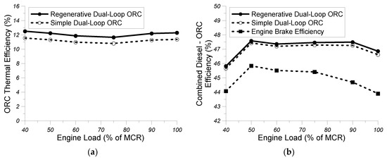
Figure 20.
Comparison of (a) Rankine cycle efficiency and (b) overall efficiency of the combined diesel engine–ORC system between the simple dual-loop ORC and the regenerative dual-loop ORC.
Figure 21a presents the comparatively assessed values of the irreversibility rate of expander 1 of the HT loop of the regenerative dual-loop ORC and the simple dual-loop ORC with engine load. As observed, the irreversibility rate of the HT loop expander in both cycles increases with engine load. Additionally, the values of the irreversibility rate of the HT loop expander are slightly higher in the case of the regenerative dual-loop ORC when compared to the corresponding ones of the simple dual-loop ORC at all examined engine loads. Specifically, the values of irreversibility rate of the HT loop expander of the regenerative dual-loop ORC range from 16.5 kW at 40% of MCR to 65 kW at 100% of MCR and the corresponding values of the simple dual-loop ORC range from 14.6 kW at 40% of MCR to 57.5 kW at 100% of MCR. The higher values of irreversibility rate at the HT loop expander of the regenerative dual-loop ORC as compared to the corresponding values of the simple dual-loop ORC can be attributed to the fact that in the regenerative cycle a portion of the organic fluid mass flow rate expands at intermediate pressure and the remaining organic fluid mass flow rate expands up to the low condensation pressure of the HT loop and these two different expansions may enhance the exergy destruction rate.
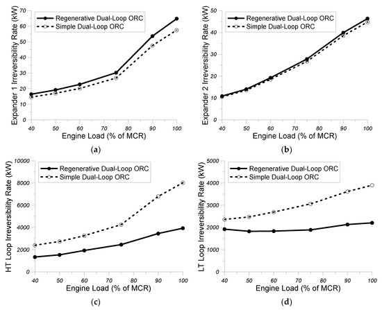
Figure 21.
Comparison of (a) irreversibility rate in the expander of the HT loop, (b) irreversibility rate in the expander of the LT loop, (c) total irreversibility rate of the HT loop, and (d) total irreversibility rate of the LT loop between the simple dual-loop ORC and the regenerative dual-loop ORC.
Figure 21b presents the comparatively evaluated values of the irreversibility rate of expander 2 of the LT loop of the regenerative dual-loop ORC with the corresponding values of the simple dual-loop ORC with engine load. As evidenced, the irreversibility rate of the expander 2 of the LT loop increases with engine load in both bottoming cycles. The differences in the irreversibility rate of the LT loop expander between the two bottoming cycles are not significant and lower when compared to the corresponding differences of irreversibility rate of the HT loop expander between the two bottoming cycles. The irreversibility rate of the LT loop expander of the regenerative dual-loop ORC varies from 10.9 kW at 40% of MCR to 46.4 kW at 100% of MCR, whereas the corresponding variation in the simple dual-loop ORC ranges from 10.5 kW at 40% of MCR to 44.8 kW at 100% of MCR.
Figure 21c illustrates the comparatively assessed values of the total irreversibility rate of the HT loop of the regenerative dual-loop ORC with the corresponding values of the simple dual-loop ORC with engine load. As observed, the total irreversibility rate of the HT loop increases with engine load in both bottoming cycles. The values of the total irreversibility rate of the HT loop of the regenerative dual-loop ORC are lower when compared to the corresponding values of the simple dual-loop ORC at all examined engine loads. Hence, an asset of the installation of the OFOH in the HT loop of the regenerative dual-loop ORC is that its operation results in the considerable reduction of the total exergy destruction rate. This is due to the fact that the OFOH results in better internal utilization of the heat transfer rates in the HT loop, since part of the high temperature organic fluid is utilized for the preheating of the low temperature organic fluid in the OFOH and this operation results in a reduction of the required thermal energy for organic fluid superheating in the HT loop. Similar observations can be made for the values of the total irreversibility rate of the LT loop between the regenerative dual-loop ORC and the simple dual-loop ORC in Figure 21d. Specifically, also in the case of the LT loop, the values of total irreversibility rate of the regenerative dual-loop ORC are lower when compared to the corresponding ones of the simple dual-loop ORC at all examined engine loads. In addition, the difference in total irreversibility rate of the LT loop between the two bottoming cycles is progressively increased with increasing engine load. The total irreversibility rate of the LT loop in the case of the regenerative ORC varies from 1921 kW at 40% of MCR to 2208 kW at 100% of MCR, whereas the total irreversibility rate of the LT loop in the case of the simple dual-loop ORC varies from 2358 kW at 40% of MCR to 3902 kW at 100% of MCR.
9.3. Mission Analysis of the General Support Vessel with Regenerative Dual-Loop ORC—Calculation of the Fuel Mass and Cost Savings and CO2 and SO2 Savings
This section examines the effect of the regenerative dual-loop ORC system on the fuel saving, fuel cost saving, CO2, and SO2 savings during a typical mission analysis of the examined general support vessel. According to the literature [40], the power consumption by the vessel propellers is provided as a function of the vessel speed according to the cube law, as follows:
Hence, for a specified mechanical efficiency nM of the reduction gear equal to 0.98, the previously mentioned constant “c” can be calculated, while using the maximum speed of the examined general support vessel, which corresponds to the maximum continuous rating (MCR) of the two main diesel engines:
Consequently, for MCR of each main engine equal to 8640 kW and for maximum vessel speed equal to 21.5 knots [20], the value of constant “c” that results from Equation (90) is: c = 12.515. Afterwards, for each vessel speed of the assumed speed profile is calculated from Equation (89) the corresponding required power from the propellers and through the mechanical efficiency of the reduction gear calculates the required generated power from the main diesel engines and the number of main diesel engines, which are coupled to the propellers. Subsequently, the data for exhaust gas mass flow rate, exhaust gas temperature, engine coolant temperature, boost air mass flow rate, and boost air temperature of the examined main diesel engine are fitted to polynomial relations as function of the generated power of the main diesel engine. Using this process, the values of exhaust gas flow rate and temperature, engine coolant temperature, and boost air mass flow rate and temperature are estimated that correspond to each speed of the examined general support vessel, as given in Table 2 The estimated values of exhaust gas mass flow rate and temperature, engine coolant temperature, and boost air mass flow rate and temperature for each vessel speed and generated power of the main diesel engine are then provided to the regenerative dual-loop ORC simulation model and results for the net power output of the ORC system are generated, which are given in Table 2. Hence, having calculated the generated electrical power of the ORC system for each vessel speed, it is assumed that this electrical power is provided to the electrical system of the examined general support vessel and, thus, the corresponding electrical power from the two auxiliary diesel generators (it is assumed that two of the three diesel generators are in operation whereas, the third diesel generator is a backup engine of other two diesel generators, which can be used in case of a severe malfunction or failure of one of the other two diesel generators) is reduced analogically. Hence, the fuel consumption in kg/h using this procedure, which is saved from the two diesel generators at each speed of the general support vessel is estimated. Assuming then, a vessel mission of 4000 h with the speed profile that is shown in Table 3, the fuel mass saving and the fuel cost saving at each vessel speed are calculated and the total fuel mass saving and the total fuel cost saving are also calculated for the entire mission of the general support vessel. For the calculation of the corresponding CO2 and SO2 savings, a simplified perfect combustion analysis of a hydrocarbon resembling to the military fuel F-76 is adopted. Specifically, the maximum sulphur content of fuel F-76 is 0.5%, its minimum hydrogen percentage is 12.5%, and its molecular weight is 205 kg/kmol, according to Ezgi and Coban [41]. Using these data, a representative composition of F-76 fuel in carbon, hydrogen, and sulphur is estimated and, then, through perfect combustion analysis shown below, it can be estimated that 1 kg F-76 fuel generates 3.2 kg CO2 and 0.01 kg SO2:
Table 2.
Values for propeller power, regenerative dual-loop ORC generated power, and mission time duration of the examined general support vessel.
Table 3.
Results for fuel savings, fuel cost savings, CO2 emission savings, and SO2 emission savings due to the previously mentioned 4000 hrs. mission analysis of the general support vessel.
Using the aforementioned analogies for CO2 and SO2 and the fuel mass saving for each vessel speed, the corresponding CO2 and SO2 savings for each vessel speed are estimated. Table 3 provides the results for fuel mass savings, fuel cost savings, CO2 and SO2 savings.
9.4. Dimensioning Results of the Heat Exchangers of the HT and the LT Loop of the Regenerative Dual-Loop ORC–Calculation of the Regenerative Dual-Loop ORC Capital Cost and Payback Period
In the previous section, it was described thoroughly the mission analysis of the general support vessel that was performed to calculate the fuel mass saving, the fuel cost saving, the CO2 emission saving, and the SO2 emission saving. Hence, the geometrical dimensions of all heat exchangers were derived based on the heat transfer analysis of the fin-and-tube heat exchanger of the evaporator 1 of the HT loop that was described in Section 5.1 and the heat transfer analysis of the plate heat exchangers of the intercooler, the preheater, the evaporator 2 of the LT loop, and the condenser that was described in Section 5.2 and the vessel speed profile of the mission analysis. Table 4 gives the main geometrical dimensions of the fin-and-tube heat exchanger of the evaporator 1 of the HT loop. Table 5 provides the main geometrical dimensions of the plate heat exchanger of the intercooler. Table 6 provides the main geometrical dimensions of the plate heat exchanger of the preheater of the LT loop. Table 7 gives the main geometrical dimensions of the plate heat exchanger of the evaporator 2 of the LT loop. Table 8 provides the main geometrical dimensions of the plate heat exchanger of the LT loop condenser.
Table 4.
Geometrical dimensions of the fin-and-tube heat exchanger of the evaporator 1 of the HT loop.
Table 5.
Geometrical dimensions of the plate heat exchanger of the intercooler.
Table 6.
Geometrical dimensions of the plate heat exchanger of the preheater of the LT loop.
Table 7.
Geometrical dimensions of the plate heat exchanger of the LT loop evaporator.
Table 8.
Geometrical dimensions of the plate heat exchanger of the LT loop condenser.
In addition, using the economic analysis that was previously described, the capital cost of each component of the regenerative dual-loop ORC was estimated. Additionally, the total capital cost and the EPC of the ORC system installation were estimated. The results for the capital cost of each component of the regenerative dual-loop ORC installation and the total capital cost and the EPC of the bottoming cycle are given in Table 9. The total capital cost of the ORC system installation is 2,546,000 Euros and the EPC is 0.2495 Euro/kWh, as evidenced from Table 9.
Table 9.
Capital costs of regenerative dual-loop ORC system components.
Table 10 presents the results of a payback period analysis that was performed to calculate the number of years that are required in order to recover the total capital cost of the regenerative dual-loop ORC system through the yearly revenues from the fuel cost savings and initiate obtaining net profits from the operation of the proposed bottoming cycle. Hence, Table 10 contains the total revenues per year that correspond to the yearly income from the fuel cost savings, the annual total expenses of the bottoming cycle installation, which correspond to the annual maintenance and insurance cost, which, according to [18], is equal to 1.65% of the total capital cost of the ORC installation. Additionally, Table 9 contains the difference between the total revenues per year and the total expenses per year and the net difference between the ORC system remaining capital cost per year and the net annual profit of the ORC system installation. As observed from Figure 10, at the end of the 9th year from the initiation of the ORC system operation the total capital cost of the ORC system will be completely covered, and the installation will be profitable by 113,356 Euros. Hence, the payback period of the proposed regenerative dual-loop ORC falls into the ninth year from the commencement of the proposed bottoming cycle operation and, because it is lower than 10 years, it can be considered as a marginally reasonable payback period.
Table 10.
Analysis of the payback period of the proposed regenerative dual-loop ORC for its onboard operation on the general support vessel.
10. Conclusions
In the present study a regenerative dual-loop ORC system was proposed to be coupled with the main diesel engines of a general support vessel. The regenerative dual-loop ORC was comprised of two loops: one high temperature (HT) loop equipped with an evaporator for recovering waste heat from exhaust gases and an open feed organic heater (OFOH), which was fed with a high temperature organic fluid that was depreciated from the expander of the HT loop at intermediate pressure and used to preheat the low temperature organic fluid before it entered the evaporator of the HT loop. The low temperature (LT) loop of the dual-loop ORC was equipped with three heat exchangers for recovering waste heat from boost air at the intercooler, for recovering waste heat from engine coolant at evaporator 2 and recovering waste heat from the organic fluid of the HT loop at the preheater of the LT loop. The LT loop was also equipped with an OFOH and a condensation heat exchanger, where the organic fluid rejects heat to the seawater. A detailed thermodynamic model was developed to perform an energetic and exergetic analysis of both HT and LT loops of the ORC system. Additionally, a thorough heat transfer analysis was conducted for estimating the heat transfer area and the main geometrical dimensions of the fin-and-tube heat exchanger of the evaporator 1 of the HT loop and the corresponding area and dimensions of the four plate heat exchangers of the LT loop. In addition, a mission analysis of the examined general support vessel was performed based on a predefined speed profile for estimating the fuel mass saving, the fuel cost saving, the CO2 emission, and the SO2 emission saving for each vessel speed, and, in total, for a 4000 h mission of the examined vessel. Finally, an economic analysis was conducted based on chemical engineering plants capital cost analysis in order to calculate the capital cost of each component of the dual-loop ORC, the total capital cost of the proposed ORC system, and the electricity production cost of the ORC system. From the detailed assessment and discussion of the theoretical findings of the present study, the following conclusions can be derived:
- The use of the OFOH in the HT loop and in the LT loop of the proposed regenerative dual-loop ORC provides higher values of the ORC system generated power and its thermal efficiency and lower values of total irreversibility rate of both HT and LT loop as compared to the simple dual-loop ORC without regeneration. Hence, the use of regeneration with OFOH in both the HT and LT loop substantially improves the energetic and exergetic performance of the dual-loop ORC.
- The installation of the proposed regenerative dual-loop ORC in a general support vessel and its operation over a specified mission results in significant savings of fuel mass, fuel consumption cost, and CO2 and SO2 emissions. Hence, the installation of the proposed ORC system in a naval support vessel can provide high energy savings and can substantially reduce its carbon and sulphur footprint.
- From an economic standpoint, the installation of the proposed regenerative dual-loop ORC in a general support vessel is economically feasible because the payback period of the ORC system capital cost can be limited to less than eight years and, in any case, can further be reduced based on the total annual time of the vessel’s mission and the annual time of the proposed ORC system operation.
Author Contributions
Conceptualization, T.C.Z.; software, A.G.V., T.C.Z. energies-13-02991-english-edits E.G.P.; validation, E.A.Y. and E.G.P.; data curation, A.G.V., K.D.A., and E.G.P.; methodology, A.G.V., T.C.Z. and E.G.P.; supervision, E.A.Y.; writing—original draft preparation, T.C.Z., J.S.K. and K.D.A.; writing—review and editing, T.C.Z., J.S.K. and K.D.A. All authors have read and agreed to the published version of the manuscript.
Funding
This research received no external funding.
Acknowledgments
Authors wish to express their sincere gratitude to the staff of the Hellenic Navy for the donation of invaluable raw of data.
Conflicts of Interest
The authors declare no conflict of interest.
Nomenclature
| A | Area (m2) |
| AHX | Heat exchanger area (m2) |
| b | Channel spacing (m) |
| B1,HX | Constant that depend on the heat exchanger type |
| B1,PP | Constant that depend from the type of the circulation pump |
| B2,HX | Constant that depend on the heat exchanger type |
| B2,PP | Constant that depend from the type of the circulation pump |
| C1,HX | Constant that depend on the type of heat exchanger |
| C1,PP | Constant that depend on the type of the circulation pump |
| C2,HX | Constant that depend on the type of heat exchanger |
| C2,PP | Constant that depend on the type of the circulation pump |
| C3,HX | Constant that depend on the type of heat exchanger |
| C3,PP | Constant that depend on the type of the circulation pump |
| CEXP | Capital cost of the expander |
| CEXP0 | Bare module cost of the expander |
| CHX | Capital cost of the heat exchanger |
| CHX | Capital cost of the heat exchanger |
| CHX0 | Bare module cost of the heat exchanger |
| CPP | Capital cost of the circulation pump |
| CPP0 | Bare module cost of the circulation pump |
| cp,sw | Seawater isobaric heat capacity (J/kgK) |
| ct | Temperature difference correction factor |
| d | Diameter (m) |
| Dh | Hydraulic port diameter (m) |
| F | Forced convective heat transfer enhancement factor |
| f | Resistance coefficient |
| fk | Maintenance and insurance cost factor |
| FM,HX | Material factor |
| FM,PP | Material factor |
| FMP | Additional expander factor |
| FP,HX | Pressure factor |
| FP,PP | Pressure factor |
| FS | Construction overhead cost factor |
| G | Mass velocity (kg/m2 s) |
| h | Convective heat transfer coefficient (W/m2 K) |
| h | Specific enthalpy (J/kg) |
| hfull_load | Full load operation hours |
| hin | Convective heat transfer coefficient of the heat exchanger internal flow (W/m2K) |
| i | Interest rate |
| Irreversibility rate (W) | |
| ifg | Enthalpy of vaporization (J/kg) |
| K1,EXP | Constant that depend on the type of the expander |
| K1,HX | Constant that depend from the heat exchanger type |
| K1,PP | Constant that depend from the type of the circulation pump |
| K2,EXP | Constant that depend on the type of the expander |
| K2,HX | Constant that depend from the heat exchanger type |
| K2,PP | Constant that depend from the type of the circulation pump |
| K3,EXP | Constant that depend on the type of the expander |
| K3,HX | Constant that depend from the heat exchanger type |
| K3,PP | Constant that depend from the type of the circulation pump |
| l | Length (m) |
| LTpl | Plant lifetime |
| m | Mass (kg) |
| Mass flow rate (kg/s) | |
| M | Molecular weight (kg/kmol) |
| n | Efficiency |
| N | Number |
| nis,exp1 | Isentropic efficiency of expander 1 |
| nis,exp2 | Isentropic efficiency of expander 2 |
| nis,p1 | Isentropic efficiency of circulation pump 1 |
| nis,p2 | Isentropic efficiency of the circulation pump 2 |
| p,p0 | Pressure (MPa) |
| Pexp1 | Net power output of expander 1 of the HT loop (W) |
| Pexp2 | Net power output of expander 2 (W) |
| PHT,net | Net power output of the HT loop (W) |
| PHX | Design pressure of the heat exchanger |
| PLT,net | Net power output of the LT loop (W) |
| Pp1 | Power consumption of the circulation pump 1 (W) |
| Pp2 | Power consumption of the circulation pump 2 (W) |
| PPP | Design pressure of the circulation pump |
| Ptot,net | Net power output of the dual-loop ORC (W) |
| Q | Heat (J) |
| Heat transfer rate (W) | |
| q | Heat flux (W/m2) |
| Imposed wall heat flux (W/m2) | |
| rin | Fouling resistance of the heat exchanger internal flow (m2 K/W) |
| rout | Fouling resistance of the heat exchanger external flow (m2 K/W) |
| s | Specific entropy (J/kgK) |
| S | Suppression factor |
| Skg/kg | Salinity (kg/kg) |
| External flow (i.e., exhaust gas) mean temperature (K) | |
| Internal flow (i.e., organic fluid) mean temperature (K) | |
| t | Temperature (°C) |
| T0 | Reference temperature of exergy destruction rate (K) |
| Tmc | Average condensation temperature of the organic fluid (K) |
| Tme | Average evaporation temperature of the organic fluid at the evaporator 2 (K) |
| U | Overall heat transfer coefficient (W/m2Κ) |
| w | Channel width (m) |
| Power consumption of the circulation pump (W) | |
| Power output of the expander (W) | |
| x | Vapor quality in the two-phase region |
| Greek | |
| α | Depreciation rate |
| β | Rib effect coefficient or chevron angle |
| δ | Fin height (m) |
| ΔTLMTD | Logarithmic mean temperature difference (K) |
| ε | Convection factor or effectiveness of the heat exchanger |
| ε | Heat exchanger effectiveness |
| λ | Thermal conductivity (W/m K) |
| μ | Dynamic viscosity () |
| ρ | Density (kg/m3) |
| Subscripts | |
| 0 | Reference |
| air | air |
| air,e | air at intercooler inlet |
| air,f | air at intercooler outlet |
| cond | Condenser |
| eq | Equivalent |
| eva1 | Evaporator 1 |
| eva2 | Evaporator 2 |
| exh | Exhaust gas |
| exp1 | Expander 1 |
| exp2 | Expander 2 |
| f | Fluid |
| fb | Film boiling |
| ft | Fin-and-tube heat exchanger |
| gas | Exhaust gas |
| gas,a | Exhaust gas at evaporator 1 inlet |
| gas,d | Exhaust gas at evaporator 1 outlet |
| H1 | Thermodynamic cycle point of the HT loop |
| H2 | Thermodynamic cycle point of the HT loop |
| H3 | Thermodynamic cycle point of the HT loop |
| H5 | Thermodynamic cycle point of the HT loop |
| H6 | Thermodynamic cycle point of the HT loop |
| H6 | Thermodynamic cycle point of the HT loop |
| H7 | Thermodynamic cycle point of the HT loop |
| H8 | Thermodynamic cycle point of the HT loop |
| HT | High temperature |
| i,in | Internal flow |
| int | Intercooler |
| ℓ,L | Liquid |
| L1 | Thermodynamic cycle point of LT loop |
| L10 | Thermodynamic cycle point of LT loop |
| L11 | Thermodynamic cycle point at LT loop |
| L11 | Thermodynamic cycle point of the LT loop |
| L2 | Thermodynamic cycle point of LT loop |
| L2is | Thermodynamic cycle point of LT loop |
| L3 | Thermodynamic cycle point of LT loop |
| L3is | Thermodynamic cycle point of LT loop |
| L5 | Thermodynamic cycle point of LT loop |
| L6 | Thermodynamic cycle point of LT loop |
| L6is | Thermodynamic cycle point of LT loop |
| L7 | Thermodynamic cycle point of LT loop |
| L8 | Thermodynamic cycle point of LT loop |
| L8is | Thermodynamic cycle point of LT loop |
| L9 | Thermodynamic cycle point of the LT loop |
| LMTD | Logarithmic mean temperature difference |
| LT | Low temperature |
| nb | Nucleate boiling |
| OFOH | Open feed organic heater |
| out | External flow |
| p1 | Circulation pump 1 |
| pla | Plate heat exchanger |
| pre | Preheater |
| tp | Two phase |
| v | Vapor |
| wall | Heat exchanger wall |
| wf | Working fluid |
| Dimensionless Numbers | |
| Bo | Boiling number |
| HX | Heat exchanger |
| Nu | Nusselt number |
| Pr | Prandtl number |
| Prexh,wall | Prandtl number of exhaust gas temperature at heat exchanger wall |
| Re | Reynolds number |
| Abbreviations | |
| bsfc | Brake specific fuel consumption |
| CEPCI | Chemical engineering plant cost index |
| CFC | chlorofluorocarbon |
| CI | Compression ignition |
| CNG | Compressed natural gas |
| CO2 | Carbon dioxide |
| CRF | Capital recovery factor |
| EPC | Electricity production cost |
| GWP | Global warming potential |
| HFC | Hydrochlorofluorocarbon |
| HFO | Hydrofluoroolefin |
| HT | High temperature |
| HX | Heat exchanger |
| LNG | Liquefied natural gas |
| LT | Low Temperature |
| MCT | Module cost technique |
| ODP | Ozone depletion potential |
| OFOH | Open feed organic heater |
| ORC | Organic Rankine cycle |
| SO2 | Sulphur dioxide |
| SW | Seawater |
| TIC | Total investment cost |
References
- Heywood, J.B. Internal Combustion Engine Fundamentals, 1st ed.; McGraw-Hill: New York, NY, USA, 1988. [Google Scholar]
- Corbett, J.J.; Winebrake, J.J.; Green, E.H.; Kasibhatla, P.; Eyring, V.; Lauer, A. Mortality from ship emissions: A global assessment. Environ Sci. Technol. 2007, 41, 8512–8518. [Google Scholar] [CrossRef] [PubMed]
- Shu, G.; Liang, Y.; Wei, H.; Tian, H.; Zhao, J.; Liu, L. A review of waste heat recovery on two-stroke IC engine aboard ships. Renew Sustain Energy Rev. 2013, 19, 385–401. [Google Scholar] [CrossRef]
- Singh, D.-V.; Pedersen, E. A review of waste heat recovery technologies for maritime applications. Energy Convers Manag. 2016, 111, 315–328. [Google Scholar] [CrossRef]
- Liu, P.; Shu, G.; Tian, H. How to approach optimal practical Organic Rankine cycle (OP-ORC) by configuration modification for diesel engine waste heat recovery. Energy 2019, 174, 543–552. [Google Scholar] [CrossRef]
- Andreasen, J.-G.; Meroni, A.; Haglind, F. A comparison of organic and steam Rankine cycle power systems for waste heat recovery on large ships. Energies 2016, 10, 547. [Google Scholar] [CrossRef]
- Li, X.; Tao, L.; Chen, L. Thermodynamic performance analysis of an improved two-stage organic Rankine cycle. Energies 2018, 11, 2864. [Google Scholar] [CrossRef]
- Shu, G.; Liu, P.; Tian, H.; Wang, X.; Jing, D. Operational profile based thermal-economic analysis on an Organic Rankine cycle using for harvesting marine engine’s exhaust waste heat. Energy Convers. Manag. 2017, 146, 107–123. [Google Scholar] [CrossRef]
- Shu, G.Q.; Liu, L.N.; Tian, H.; Wei, H.Q.; Yu, G.P. Parametric and working fluid analysis of a dual-loop organic Rankine cycle (DORC) used in engine waste heat recovery. Appl. Energy 2014, 113, 1188–1198. [Google Scholar] [CrossRef]
- Song, J.; Song, Y.; Gu, C.-W. Thermodynamic analysis and performance optimization of an Organic Rankine Cycle (ORC) waste heat recovery system for marine diesel engines. Energy 2015, 82, 976–985. [Google Scholar] [CrossRef]
- Song, J.; Gu, C.-W. Parametric analysis of a dual loop Organic Rankine Cycle (ORC) system for engine waste heat recovery. Energy Convers Manag. 2015, 105, 995–1005. [Google Scholar] [CrossRef]
- Song, J.; Gu, C.-W. Performance analysis of a dual-loop organic Rankine cycle (ORC) system with wet steam expansion for engine waste heat recovery. Appl Energy 2015, 156, 280–289. [Google Scholar] [CrossRef]
- Sung, T.; Kim, K.-C. Thermodynamic analysis of a novel dual-loop organic Rankine cycle for engine waste heat and LNG cold. Appl. Therm. Eng. 2016, 100, 1031–1041. [Google Scholar] [CrossRef]
- Yao, B.; Yang, F.; Zhang, H.; Wang, E.; Yang, K. Analyzing the performance of a dual loop organic Rankine cycle system for waste heat recovery of a heavy-duty compressed natural gas engine. Energies 2014, 7, 7794–7815. [Google Scholar] [CrossRef]
- Zhang, H.G.; Wang, E.H.; Fan, B.Y. A performance analysis of a novel system of a dual loop bottoming organic Rankine cycle (ORC) with a light-duty diesel engine. Appl. Energy 2013, 102, 1504–1513. [Google Scholar] [CrossRef]
- Zhao, M.; Wei, M.; Song, P.; Liu, Z.; Wang, Z. Effects of ORC operating conditions on the engine performance for an engine-ORC combined system. Energy Procedia 2017, 105, 662–667. [Google Scholar] [CrossRef]
- Zhou, Y.; Wu, Y.; Li, F.; Yu, L. Performance analysis of zeotropic mixtures for the dual-loop system combined with internal combustion engine. Energy Convers Manag. 2016, 118, 406–414. [Google Scholar] [CrossRef]
- Yang, F.; Cho, H.; Zhang, H.; Zhang, J. Thermoeconomic multi-objective optimization of a dual loop organic Rankine cycle (ORC) for CNG engine waste heat recovery. Appl. Energy 2017, 205, 1100–1118. [Google Scholar] [CrossRef]
- Scardigno, D.; Fanelli, E.; Viggiano, A.; Braccio, G.; Magi, V. A genetic optimization of a hybrid organic Rankine plant for solar and low-grade energy sources. Energy 2015, 91, 807–815. [Google Scholar] [CrossRef]
- Hellenic Navy Website. Available online: http://www.hellenicnavy.gr/en/ (accessed on 10 May 2020).
- Hellenic Navy staff. Personal communication, 2020.
- Yang, F.B.; Dong, X.R.; Zhang, H.G.; Wang, Z.; Yang, K.; Zhang, J.; Wang, E.H.; Liu, H.; Zhao, G.Y. Performance analysis of waste heat recovery with a dual loop organic Rankine cycle (ORC) system for diesel engine under various operating conditions. Energy Convers Manag. 2014, 80, 243–255. [Google Scholar] [CrossRef]
- Usman, M.; Imran, M.; Yang, Y.M.; Park, B.S. Impact of organic Rankine cycle system installation on light duty vehicle considering both positive and negative aspects. Energy Convers Manag. 2016, 12, 382–394. [Google Scholar] [CrossRef]
- Macián, V.; Serrano, J.R.; Dolz, V.; Sánchez, J. Methodology to design a bottoming Rankine cycle, as a waste energy recovering system in vehicles. Study in a HDD engine. Appl. Energy 2013, 104, 758–771. [Google Scholar] [CrossRef]
- Wang, E.H.; Zhang, H.G.; Fan, B.Y.; Ouyang, M.G.; Zhao, Y.; Mu, Q.H. Study of working fluid selection of organic Rankine cycle (ORC) for engine waste heat recovery. Energy 2011, 36, 3406–3418. [Google Scholar] [CrossRef]
- Yang, M.-H.; Yeh, R.-H. Thermodynamic and economic performances optimization of an organic Rankine cycle system utilizing exhaust gas of a large marine diesel engine. Appl. Energy 2015, 149, 1–12. [Google Scholar] [CrossRef]
- Xi, H.; Li, M.J.; Xu, C.; He, Y.L. Parametric optimization of regenerative organic Rankine cycle (ORC) for low grade waste heat recovery using genetic algorithm. Energy 2013, 58, 473–482. [Google Scholar] [CrossRef]
- Imran, M.; Park, B.S.; Kim, H.J.; Lee, D.H.; Usman, M.; Heo, M. Thermo-economic optimization of regenerative organic Rankine cycle for waste heat recovery applications. Energy Conv. Manag. 2014, 87, 107–118. [Google Scholar] [CrossRef]
- Nayar, K.G.; Sharqawy, M.H.; Banchik, L.D.; Lienhard, V.J.H. Thermophysical properties of seawater: A review and new correlations that include pressure dependence. Desalination 2016, 390, 1–24. [Google Scholar] [CrossRef]
- Cao, E. Heat Transfer in Process Engineering; McGraw Hill: New York, NY, USA, 2010; ISBN 978-0-07-162408-4. [Google Scholar]
- Zukauskas, A. Heat Transfer from Tubes in Cross Flow. Adv Heat Transfer; Academic Press: New York, NY, USA, 1972; pp. 93–106. [Google Scholar]
- Gnielinski, V. New equations for heat mass transfer in turbulent pipe and channel flows. Int. Chem. Eng. 1976, 16, 359–368. [Google Scholar]
- Liu, Z.; Whinterton, R.H.S. A general correlation for saturated and subcooled flow boiling in tubes and annuli based on nucleate boiling equation. Int. J. Heat Mass Transfer. 1991, 34, 2759–2766. [Google Scholar] [CrossRef]
- García-Cascales, J.R.; Vera-García, F.; Corberán-Salvador, J.M.; Gonzálvez-Maciá, J. Assessment of boiling and condensation heat transfer correlations in the modelling of plate heat exchangers. Int. J. Refrig. 2007, 30, 1029–1041. [Google Scholar] [CrossRef]
- Yan, Y.Y.; Lio, H.C.; Lin, T.F. Condensation heat transfer and pressure drop of refrigerant R-134a in a plate heat exchanger. Int. J. Heat Mass Transfer 1999, 42, 993–1006. [Google Scholar] [CrossRef]
- Yan, Y.Y.; Lin, T.F. Evaporation heat transfer and pressure drop of refrigerant R-134a in a plate heat exchanger. J. Heat Transfer ASME Trans 1999, 121, 118–127. [Google Scholar] [CrossRef]
- Turton, R.; Bailie, R.C.; Whiting, W.B.; Shaeiwitz, J.A. Analysis, Synthesis and Design of Chemical Processes; Prentice Hall: Upper Saddle River, NJ, USA, 2008. [Google Scholar]
- Nafey, A.S.; Sharaf, M.A. Combined solar organic Rankine cycle with reverse osmosis desalination process: Energy, exergy, and cost evaluations. Renew Energy 2010, 35, 2571–2580. [Google Scholar] [CrossRef]
- Average Temperatures of Surface Water of Greek Seas. Available online: http://www.meteoclub.gr/themata/egkyklopaideia/5321-meses-thermokrasies-thalasson (accessed on 10 May 2020).
- MAN Diesel & Turbo. Basic Principles of Ship Propulsion. Available online: https://marine.man-es.com/docs/librariesprovider6/propeller-aftship/5510-0004-04_18-1021-basic-principles-of-ship-propulsion_web.pdf?sfvrsn=c01858a2_8 (accessed on 10 May 2020).
- Ezgi, C.; Coban, M.T. Modeling study of solid oxide fuel cell operating on reformed NATO F-76 diesel fuel. J. Naval Sci. Eng. 2012, 8, 57–86. [Google Scholar]
© 2020 by the authors. Licensee MDPI, Basel, Switzerland. This article is an open access article distributed under the terms and conditions of the Creative Commons Attribution (CC BY) license (http://creativecommons.org/licenses/by/4.0/).