Article

Inertia and Droop Frequency Control Strategy of Doubly-Fed Induction Generator Based on Rotor Kinetic Energy and Supercapacitor

Key Laboratory of Distributed Energy Storage and Micro-Grid of Hebei Province, North China Electric Power University, Baoding 071003, China
*
Author to whom correspondence should be addressed.
Energies 2020, 13(14), 3697; https://doi.org/10.3390/en13143697
Submission received: 13 June 2020 / Revised: 9 July 2020 / Accepted: 16 July 2020 / Published: 17 July 2020
(This article belongs to the Section A3: Wind, Wave and Tidal Energy)

Abstract

:
The large-scale application of wind power eases the shortage of conventional energy, but it also brings great hidden danger to the stability and security of the power grid because wind power has no ability for frequency regulation. When doubly-fed induction generator (DFIG) based wind turbines use rotor kinetic energy to participate in frequency regulation, it can effectively respond to frequency fluctuation, but has the problems of secondary frequency drop and output power loss. Furthermore, it cannot provide long-term power support. To solve these problems, a coordinated frequency control strategy based on rotor kinetic energy and supercapacitor was proposed in this paper. In order to ensure the DFIG provides fast and long-term power support, a supercapacitor was used to realize the droop characteristic, and rotor kinetic energy was used to realize the inertia characteristic like synchronous generator (SG). Additionally, the supercapacitor is also controlled to compensate for the power dip of the DFIG when rotor kinetic energy exits inertia support to avoid secondary frequency drop. Additionally, a new tracking curve of DFIG rotor speed and output power was adopted to reduce the power loss during rotor speed recovery.

Graphical Abstract

1. Introduction

In recent years, the penetration of renewable energy connected to the power grid continues to increase. As an important part of renewable energy, wind power’s installed capacity reached 200 million kilowatts by 2019 [1]. However, the large-scale application of wind power also brings hidden dangers to the safety of the power grid and increases the difficulty of system frequency regulation. Doubly-fed induction generator (DFIG) is one of the main types in the current wind power market. It usually operates at a maximum power point tracking (MPPT) state [2], in which the rotor speed is completely decoupled from system frequency. In this state, DFIG does not have the inertia characteristic and droop characteristic like a synchronous generator (SG). Therefore, a power grid with a DFIG will show weak stability when facing system frequency fluctuations [3].
In response to this problem, it is required that grid-connected wind farms should have the capability of inertia response and primary frequency support in wind power grid connection guidelines [4,5,6]. The existing methods about DFIG participating in frequency regulation can be divided into three categories including using rotor kinetic energy, keeping reserve power, and introducing energy storage equipment. In the control strategy of using rotor kinetic energy, the droop loop and inertia loop for inertial control are introduced to couple rotor speed with frequency deviation and change rate of frequency [7,8,9], so that the DFIG can absorb or release rotor kinetic energy to participate in frequency regulation. However, this strategy has the problem of secondary frequency drop during rotor speed recovery and the DFIG cannot provide long-term power support. In the control strategy of keeping reserve power, the DFIG maintains a certain reserve power through the means of over-speed control or pitch control [10,11,12], so the DFIG can provide primary frequency regulation and long-term power support. However, in this method, the DFIG operates at the load shedding state in normal condition, which causes a great waste of wind energy resources. In the control strategy of introducing energy storage equipment, a supercapacitor installed at the direct current (DC) link of the DFIG back-to-back converter [13,14] and a battery installed at the exit bus of the wind farm [15] are adopted as the virtual inertia source to provide power support, which ensures that the DFIG operates at maximum power point tracking (MPPT) state all the time. However, the cost and capacity of the energy storage device will increase greatly because it only adopts an energy storage device to provide energy support and rotor kinetic energy does not work. Therefore, if relying only on an energy storage device or rotor kinetic energy to participate in frequency regulation, it cannot meet the power grid’s requirements for a DFIG that simultaneously has a frequency regulation ability and maximum economic benefit.
Coordination control regarding energy storage devices has been widely developed in solving wind power problems including smoothing the output active power of wind farms, suppressing the shafting oscillation of the DFIG, and assisting the DFIG to realize low-voltage ride through [16,17]. It also provides a new idea for coordinating the DFIG and energy storage to participate in frequency regulation. In [18,19,20,21,22,23,24], energy storages and rotor kinetic energy were coordinated as the inertial source to improve the frequency dynamic response capability of DFIG. As for the selection of energy storage, a supercapacitor [18,19,20], battery [21,22,23], and hydrogen energy storage [24] can all be used as inertia sources to coordinate with the DFIG. In terms of the coordination control strategy, [19] adopted the fuzzy logic controller to realize the inertia response of the DFIG under variable wind speeds; [20] used cascading control strategy to coordinate the rotor kinetic energy and battery, thus achieving the short-time inertia support of the DFIG under full wind speed; [21] explored the inertial response capability of a battery-embedded DFIG and used it to provide power support in synchronous, supersynchronous, and subsynchronous operations; [22] utilized an adaptive fuzzy control to achieve the inertia support of the DFIG under full wind speed; and [24] adopted a torque limit strategy to control rotor kinetic energy and participate in frequency regulation, and utilized a battery to solve the secondary frequency drop caused by the torque limit control. Although the above studies [18,19,20,21,22,23,24] all improved the DFIG inertia support capacity in a short-time, none of them studied the application of an energy storage device in long-term power support and primary frequency regulation. Furthermore, they all adopted MPPT as the tracking curve during rotor speed recovery, and did not consider the output active power loss. Although energy storage was introduced to realize primary frequency regulation in [25,26], they did not mention the implementation of the inertia characteristic of the DFIG. Thus at present, there is no research to coordinate an energy storage device and DFIG to realize inertia support and primary frequency regulation.
Based on the above studies, inertial and droop frequency control strategy based on the rotor kinetic energy and supercapacitor was proposed in this paper, and its configuration schematic is shown in Figure 1. Compared with the existing strategies, it has the following contributions.
(1) By coordinating rotor kinetic energy and the supercapacitor, DFIG has inertial and droop characteristics like SG, which makes the DFIG realize the inertial response and primary frequency regulation.
(2) A new tracking curve of DFIG output power and rotor speed is proposed in the approach, which can effectively reduce the power loss during rotor speed recovery.
(3) By controlling the output power mode of supercapacitor, power dip of the DFIG happened at the rotor kinetic energy exiting, power support is solved, and secondary frequency drop is also avoided.

2. Rotor Kinetic Energy of the Doubly-Fed Induction Generator (DFIG)

2.1. Inertial Support Capacity of Rotor Kinetic Energy

Inertia reflects the characteristic where the unit uses its rotor kinetic energy to restrain the change of system frequency. In power system, inertia time constant H is usually utilized to represent this action characteristic.
H = E k S N = J ω N 2 2 S N
where H is the inertial time constant; Ek is the rotor kinetic energy; J is the moment of inertia; ω N is the rated rotor speed; and SN is the rated power.
The rotor speed of SG generally operates in the range of 1–0.96 pu when it participates in system frequency regulation. When the rotor speed is 0.96 pu, system frequency is in the lower limit value of 48 Hz, and SG releases the maximum rotor kinetic energy [15,24].
Δ E k = E 0 E 1 = 1 2 J ( ω 0 2 ω 1 2 )
Δ E k max = 1 2 J ( 1 0.96 2 ) ω N 2 = 0.0392 J ω N 2 = 0.0784 H S N
where Δ E k is the released rotor kinetic energy; E0 is the rotor kinetic energy corresponding to the initial rotor speed ω 0 ; E1 is the rotor kinetic energy corresponding to rotor speed ω 1 , whose unit has participated in frequency regulation.
In order to make the DFIG provide inertia support like SG, the first step is to analyze whether the DFIG has enough rotor kinetic energy and quantify the inertia support capacity of the DFIG. Take a DFIG of 2 MW and a SG with the same power for comparison and substitute the related parameters into (2) and (3), the rotor kinetic energy released by the DFIG and SG can be calculated. When the SG’s inertia time constant is H = 5 s [8], the released maximum rotor kinetic energy is 0.784 MJ. In general, the rotor kinetic energy released by the SG is less than 0.784 MJ because the system frequency is usually higher than 48 Hz. As for the DFIG, it can be seen from (2) that the released rotor kinetic energy is related to its initial rotor speed and the operating range of the DFIG rotor speed is generally 0.7 pu–1.2 pu. When the DFIG’s moment of inertia is J = 7.4779 × 10 6   k g m 2 [27], rotor kinetic energy released by the DFIG at different rotor speeds can be obtained according to (2). It can be concluded from Table 1 that the DFIG has the rotor kinetic energy of 1.57 MJ, even at a low speed of 0.8 pu, which is twice as much as the maximum energy released by SG. In other rotor speeds, the energies are all higher than 0.784 MJ. Therefore, the DFIG has enough rotor kinetic energy to provide inertia support like the SG.
When the DFIG participates in system frequency regulation with 10% rated power, the power support time can be calculated in (4). Considering that mechanical power Pm is not constant during rotor speed decrease, it is necessary to calculate the energy loss caused by the mechanical power.
Δ t = Δ E k Δ P m Δ t 0.1 P N = Δ E k [ P m ( ω 0 ) P m ( ω 1 ) ] Δ t 0.1 P N
P m = 1 2 ρ Π R 2 v 3 C P ( ω r R v , β )
where Δ t is the power support time; Pm is the mechanical power of DFIG; PN is the rated power of DFIG; ρ is the air density; R is the blade radius of wind turbine; v is the wind speed; ω r is the rotor speed; β is the pitch angle; and C p is the wind power coefficient.
It is shown in Table 1 that the shortest power support time was 6.02 s, which corresponds to the rotor speed of 0.8 pu. In other rotor speeds, the power support times were all higher than 6.02 s. Therefore, the DFIG can provide inertia support of not less than 5 s, like the SG. However, if the DFIG is required to provide power regulation for long time, the energy is far from sufficient.

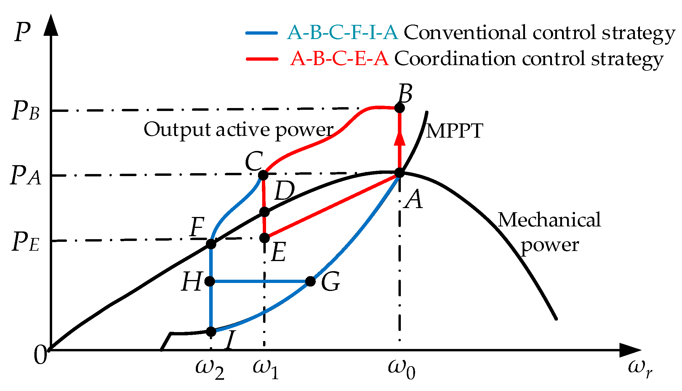
2.2. Conventional Frequency Control Strategy Based on Rotor Kinetic Energy

In order to maximize the utilization of wind power, the DFIG usually operates in the MPPT state. The MPPT curve consists of the maximum mechanical power points at different wind speeds. In this state, the output power of DFIG is PMPPT [22].
P M P P T = 1 2 ρ Π R 2 C p max ω r 3
where PMPPT is output power in MPPT curve and C p max is the maximum wind power coefficient.
If the DFIG operates in the MPPT state all the time, it has no ability to respond to frequency fluctuation. Therefore, some scholars have considered using rotor kinetic energy to realize inertia and droop control when the DFIG participates in system frequency regulation. In a conventional frequency control strategy based on rotor kinetic energy, the control block diagram is shown in Figure 2 [7], and the expression of the DFIG output active power is as follows.
P r e f = P M P P T Δ P 1 Δ P 2 = P M P P T 2 H d f d t D Δ f
where Pref is the reference value of the output active power; PMPPT is the output power in the MPPT curve; H is the inertia time constant; D is the droop coefficient; Δ P 1 is the additional inertia power; Δ P 2 is the additional droop power; f is the system frequency; Δ f is the system frequency deviation; and d f / d t is the frequency change rate.
In the normal condition, the system frequency is equal to the rated value, and the additional power Δ P 1 and Δ P 2 are both zero, and the DFIG operates at MPPT state point A (shown in Figure 3). When the system frequency changes, the DFIG starts to participate in frequency regulation. If system frequency is below the rated value, the additional inertia power Δ P 1 and droop power Δ P 2 will be greater than zero under the excitation of frequency change rate d f / d t and frequency deviation Δ P 2 . The reference value of output active power Pref will be larger than the power of PA. As the mechanical power remains constant at the moment of frequency change, the output power of the DFIG will be greater than it. Thus, the DFIG will decrease its rotor speed and release the rotor kinetic energy to provide power support. With the release of rotor kinetic energy, the additional power Δ P 1 , Δ P 2 , and DFIG output power Pref will gradually decrease, and the system frequency will also return to the rated value. Therefore, the DFIG realizes the function of effectively responding to frequency fluctuation and participating in frequency regulation. In this stage, the operation curve of DFIG output power and rotor speed is A–B–C.

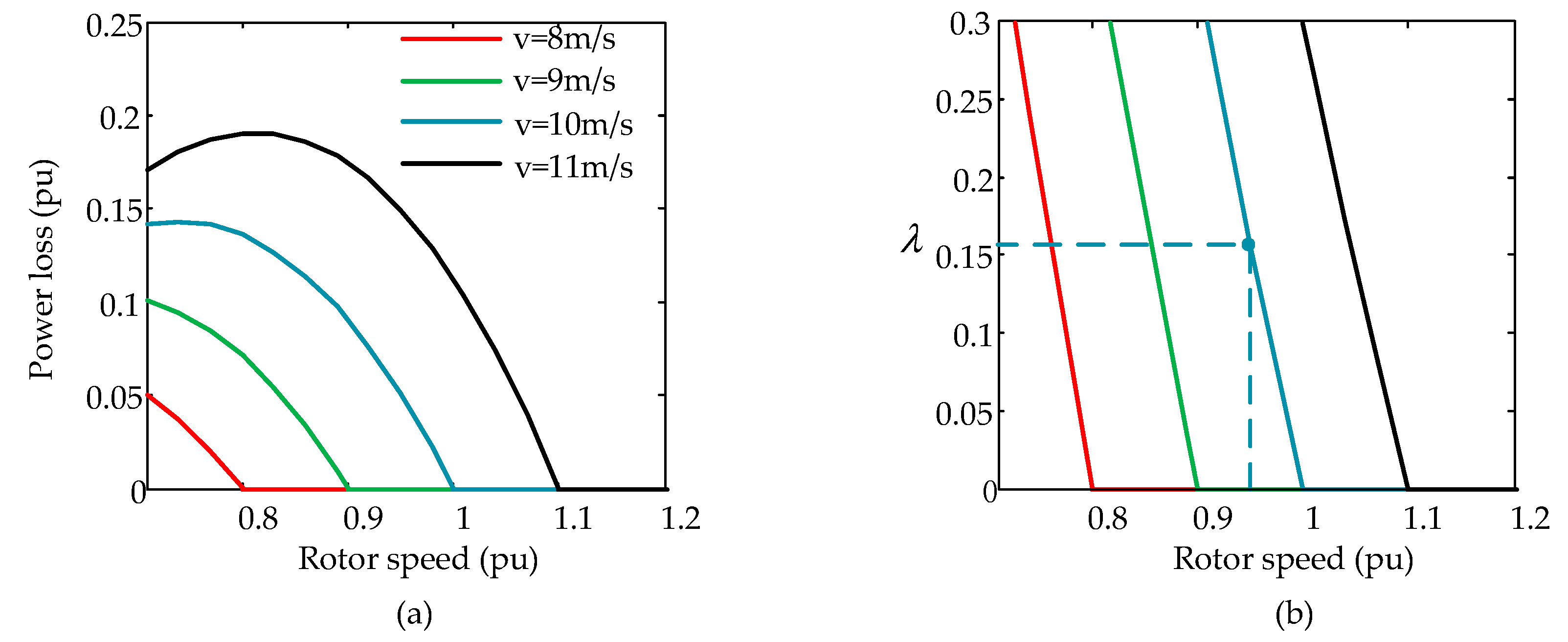
2.3. Power Dip and Power Loss during Rotor Speed Recovery

In the conventional frequency control strategy, the DFIG will exit frequency regulation and recovery to the maximum power point A when the rotor speed decreases to ω 2 . Different rotor speed recovery strategies were proposed in [28,29,30] including the delay recovery strategy, the switching control parameter recovery strategy, and the fixed output power recovery strategy. In these strategies, the DFIG either adopts F–I–A (blue curve in Figure 3) as the tracking curve of the rotor speed and output power or takes F–H–G–A as a tracking curve. F–I–A curve directly selects the MPPT curve as the reference value of output active power. The F–H–G–A curve maintains at H point for a period of time and then takes the MPPT curve as the reference value. However, they both have the problems of output active power dip and output active power loss.
For the output active power dip, it refers to the power of Δ P F I or Δ P F H . When the DFIG exits frequency regulation, the additional power Δ P 1 and Δ P 2 reduce to zero, and the output active power decreases instantaneously. Then, the system will have a power shortage of Δ P F I or Δ P F H , which will cause the phenomenon of secondary frequency drop. When the wind speed is 10 m/s, the value of secondary frequency drop in different power dip is shown in Figure 4. It can be concluded that the value of secondary frequency drop rises with the increase in power dip and it is proportional to the output active power dip. When the power dip reaches 0.05 pu, the value of system secondary frequency drop is almost equivalent to the primary frequency deviation. If it is not controlled, the drop degree will be more serious.
For the output active power loss, it refers to the difference between mechanical power and MPPT power. During rotor speed recovery, the MPPT curve will be adopted as a part or all of the output power reference value. However, the DFIG only outputs the maximum power at point A, and it is in the deceleration state on the other operating points of the MPPT curve. Therefore, the power loss cannot be output effectively, and it is only used for the acceleration of rotor speed. When the DFIG adopts the MPPT curve, that is F–I–A, as the reference value of output active power during rotor speed recovery, the expression of output active power loss is shown in (8).
P l o s s = P m P M P P T = 1 2 ρ Π R 2 v 3 C P ( ω r R v , β ) 1 2 ρ Π R 2 C p max ω r 3
where Ploss is the power loss; Pm is the mechanical power of the DFIG; and PMPPT is the output power in MPPT curve.
When wind speed is determined, the output active power loss Ploss is a function of rotor speed ω r and the power loss under different wind speeds can be calculated according to (8). Aside from the power loss percentage λ , that is, the ratio of the output active power loss and DFIG real output active power, can also be obtained.
λ ( ω r , v ) = P l o s s P M P P T = P m P M P P T P M P P T
It is shown in Figure 5a that the output active power loss increases with the rise in wind speed and decreases with the recovery of rotor speed. When the wind speed is 10 m/s, the rotor speed is 1 pu in the normal condition. If the DFIG participates in frequency regulation and the rotor speed decreases to 0.96 pu, the initial power loss percentage λ is 17% (in Figure 5b), which is approximately one sixth of the real active output power and causes a significant loss of DFIG output power. Although the power loss percentage gradually decreases to zero with rotor speed recovery, the processing cannot be completed in a few seconds. If the recovery process is too slow, the DFIG will be in a deceleration state for a long time, which will cause a lot of waste of wind resources.

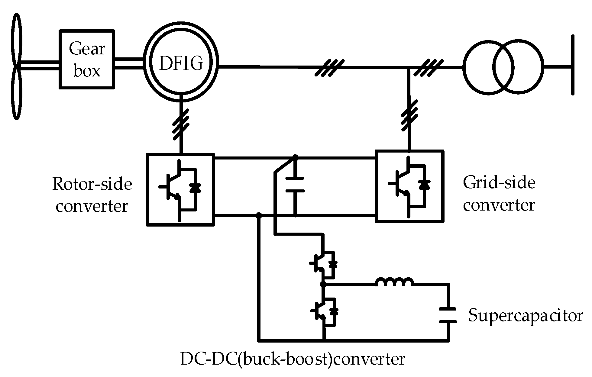
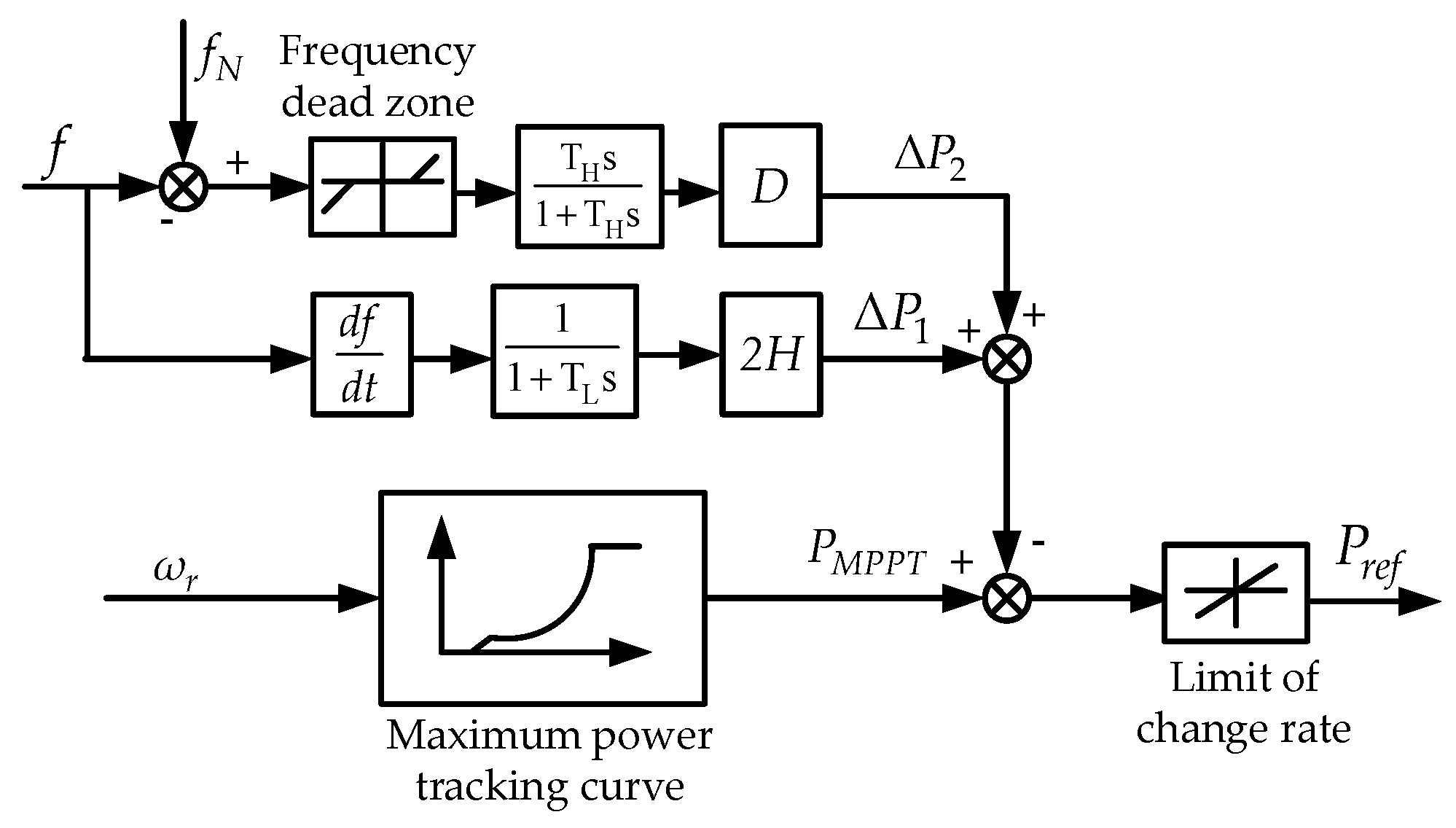
3. Frequency Regulation Scheme Based on Rotor Kinetic Energy and Supercapacitor

Considering that the conventional frequency control strategy based on rotor kinetic energy has the problems of power dip and power loss during rotor speed recovery, which will cause secondary frequency drop and output power reduction, an inertia and droop frequency control strategy based on rotor kinetic energy and supercapacitor was proposed in this paper. It not only solves the above problems, but also ensures that the DFIG can provide long-term frequency regulation.

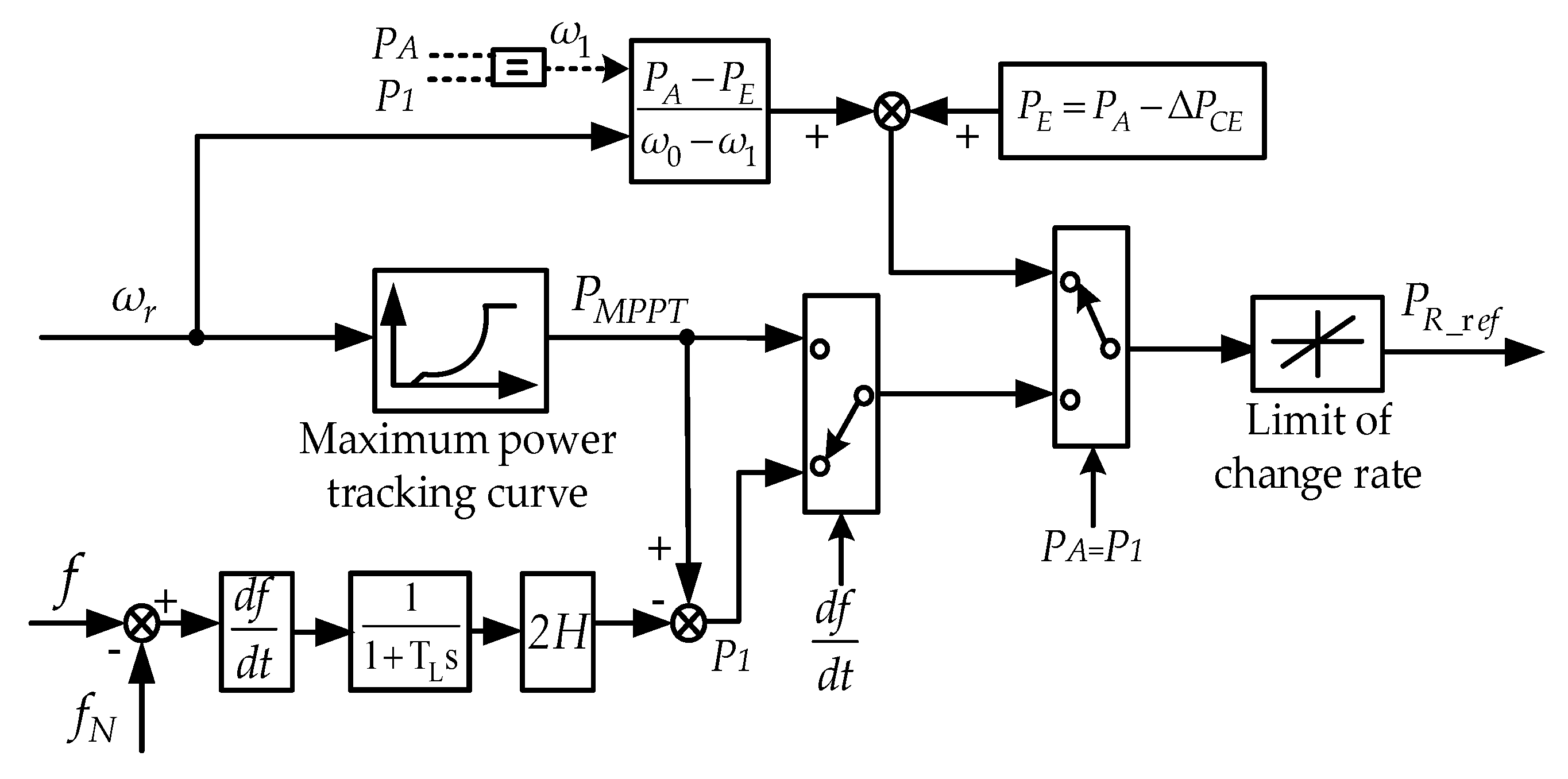
3.1. Rotor Kinetic Energy Control Mode of the DFIG

It was proven in Section 2.1. that the rotor kinetic energy contained in the DFIG can provide inertia support of not less than 5 s, which meets the system requirements of inertia response for the DFIG [6]. However, if rotor kinetic energy is required to simulate the droop characteristic and provide long-term power support like in (7), the energy is far from sufficient. Therefore, rotor kinetic energy is only controlled to simulate the inertia characteristic and response frequency change rate d f / d t in the strategy. During a fault, the DFIG follows the A–B–C–E–A curve (red curve in Figure 3).
In the normal condition, the DFIG operates at the maximum power point A. If system frequency fluctuates due to power unbalance, the DFIG will respond to the change in system frequency instantaneously and release its rotor kinetic energy to provide inertia support. In the inertia response period A–B–C, the reference value of the DFIG output active power is as follows:
P R _ r e f = P M P P T 2 H d f d t
where PR_ref is the reference value of DFIG output active power; PMPPT is the output power in the MPPT curve; and H is the inertia time constant.
With the continuous release of rotor kinetic energy, the change rate of system frequency will slow down, and the output active power of the DFIG will also decrease. When the output power decreases to PC, which is equal to the maximum power PA before fault, the DFIG is in the critical state of inertia support. If the rotor speed and output power continue to decrease, in fact, the DFIG with an additional inertia loop will no longer have the function of power support. Therefore, inertia support (that is rotor kinetic energy) of the DFIG is set to exit at point C so that the DFIG output active power can reach the maximum.
When the DFIG enters the rotor speed recovery period, a new tracking curve of output power and rotor speed E–A is proposed to reduce the output active power loss. A is the maximum power point in the MPPT curve. Its power PA can be obtained from (11-1), and its rotor speed ω 0 can be obtained before the fault. E is the starting point of speed recovery. Its rotor speed ω 1 is the same with point C and can be calculated from (11-2). Its power PE is determined by Δ P C E and can be obtained from (11-3). For Δ P C E , it not only affects the rotor speed recovery time, but also affects the output active power loss, and the two factors contradict each other. Therefore, Δ P C E shall be determined dynamically in different system events, and the same experiment was also conducted in Section 4.2. The selection criteria of Δ P C E is to shorten the rotor speed recovery time on the premise of minimizing the power loss. Furthermore, point E must be below point D because if the rotor speed is kept to accelerate, the output active power PE must be smaller than the mechanical power PD. In the rotor speed recovery period E–A, the reference value of the DFIG output active power is shown in (10).
P R _ r e f = P E + P A P E ω 0 ω 1 ω 1
{ P A = P M P P T ( ω 0 ) P M P P T ( ω 1 ) 2 H d f d t = P A P E = P A Δ P C E
where PA and ω 0 are the power and rotor speed of point A; PE and ω 1 are the power and rotor speed of point E; and Δ P C E is the power difference of PA and PE.
According to (10) and (11), the control block diagram of rotor kinetic energy in different response periods can be obtained and is shown in Figure 6.

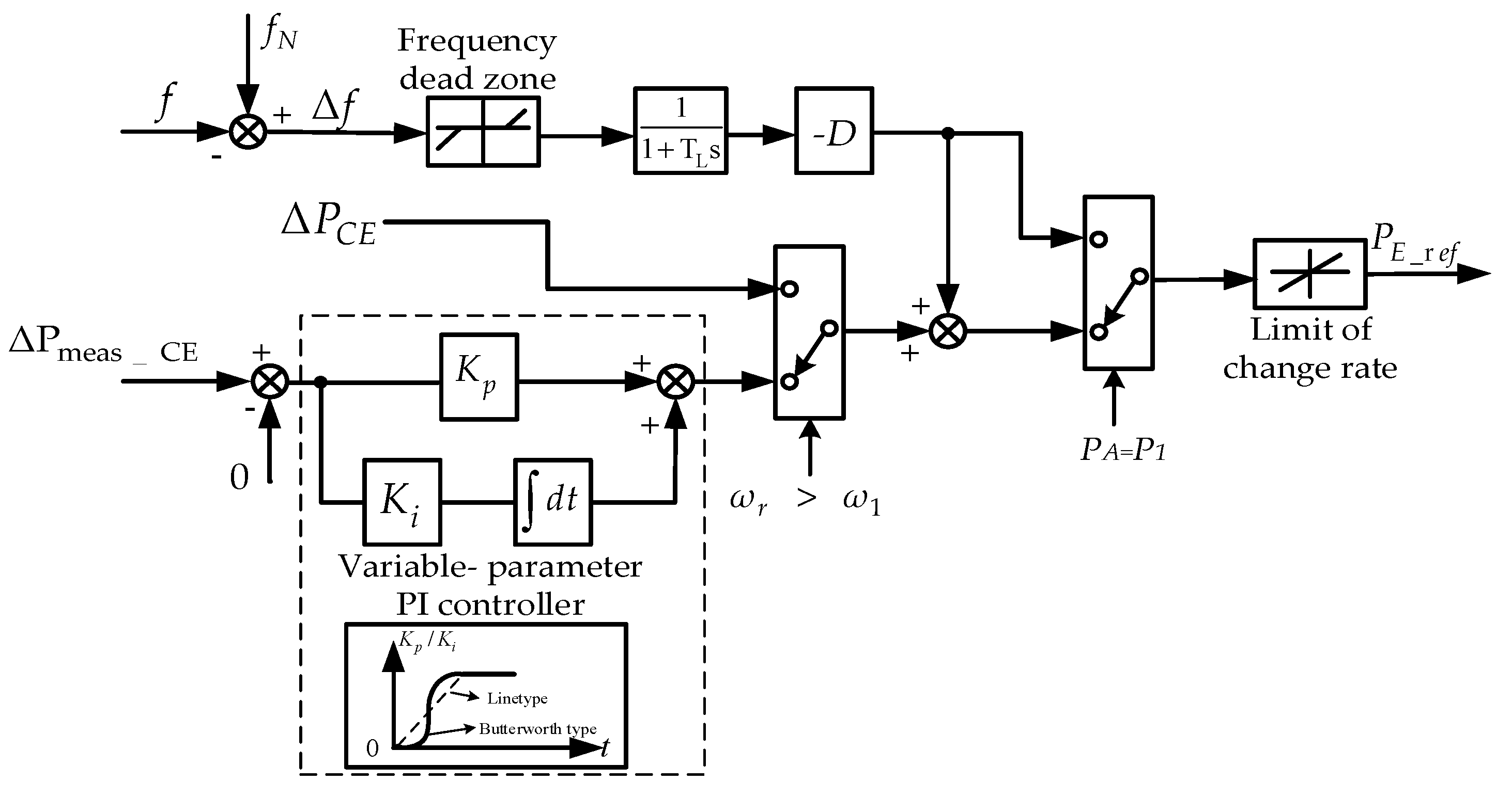
3.2. Supercapacitor Control Mode

It was proven in Section 2.1 that the rotor kinetic energy of DFIG was far from enough to provide long-term power support. Thus, in the strategy, the energy storage device discharges to participate in primary frequency regulation and make the DFIG have a droop characteristic like the SG. In addition, the energy storage device is also controlled to compensate the output active power dip of the DFIG and avoid the phenomenon of secondary frequency drop.
For the selection of the energy storage device, it is necessary to consider the requirements of the power grid for frequency regulation. On one hand, the power grid frequency changes frequently, and the number of exceeding frequency dead zones can reach thousands of times in a frequency day [30]. On the other hand, the system requires the response speed of unit that participates in frequency regulation to the order of seconds. As a supercapacitor has the characteristics of high cycle times, fast charging, and discharging speed, which meet the system requirements [26], a supercapacitor was selected as the energy storage device.
In the normal condition, the output active power of supercapacitor is zero. When frequency deviation exceeds the frequency dead zone of 0.033 Hz [6,30], the supercapacitor discharges and releases its stored energy to participate in frequency regulation. In this period, the output active power of the supercapacitor is as follows:
P E _ r e f = D Δ f
where PE_ref is the output power reference value of supercapacitor and D is the droop coefficient.
When the rotor kinetic energy exits the inertia support, DFIG will have a power dip of Δ P C E . Therefore, the supercapacitor is controlled to change its output power mode at the moment and compensate the power dip, in order to avoid the occurrence of secondary frequency drop.
P E _ r e f = D Δ f + Δ P C E
If the output part Δ P C E of the supercapacitor remains constant all the time, the output power of the DFIG will be greater than the power shortage during rotor speed recovery, and it may lead to frequency overshoot. Therefore, the PI regulator link (as shown in Figure 7) is introduced to reduce Δ P C E to 0 slowly and decrease power fluctuation. In the selection of the PI regulator, considering that the constant parameter PI regulator has the problem of output power sudden change, and linear variable parameter PI regulator has the problem that output power is difficult to adjust in time, the variable parameter PI regulator based on Butterworth function was chosen to reduce the impact of the Δ P C E ’s exit. When the rotor speed starts to increase (i.e., ω r > ω 1 ), the Δ P C E ’s actual output value Δ P m e a s _ C E (measured in the supercapacitor outlet) and the reference value 0 are controlled as the input of the PI regulator. By continuously adjusting the PI regulator, the output part Δ P m e a s _ C E of the supercapacitor will be reduced to 0 slowly, and the DFIG will recover to the only stable point A. In this period, the reference value of the supercapacitor output power is shown in (14).
P E _ r e f = D Δ f + K p ( Δ P m e a s _ C E 0 ) + K i ( Δ P m e a s _ C E 0 ) d t
where Kp and Ki are the proportional coefficient and integral coefficient of the PI regulator, and Δ P m e a s _ C E is the part output power of the supercapacitor.
During this process, the supercapacitor releases its energy and discharges to participate in frequency regulation and the control block diagram of the supercapacitor in different response periods can be obtained according to (12)–(14), which is shown in Figure 7.
In the above control mode, the supercapacitor discharges and supplies its power to the system. However, if its energy is not sufficient, it also needs to get charged. When the frequency fluctuates, the supercapacitor is controlled to release its energy to participate in frequency regulation, thus the supercapacitor can get charged in the normal condition. Considering that constant power charging mode [31,32] has more advantages in charging time and charging efficiency, it is used in the supercapacitor getting charge from the power grid by the external charging device [33,34,35].

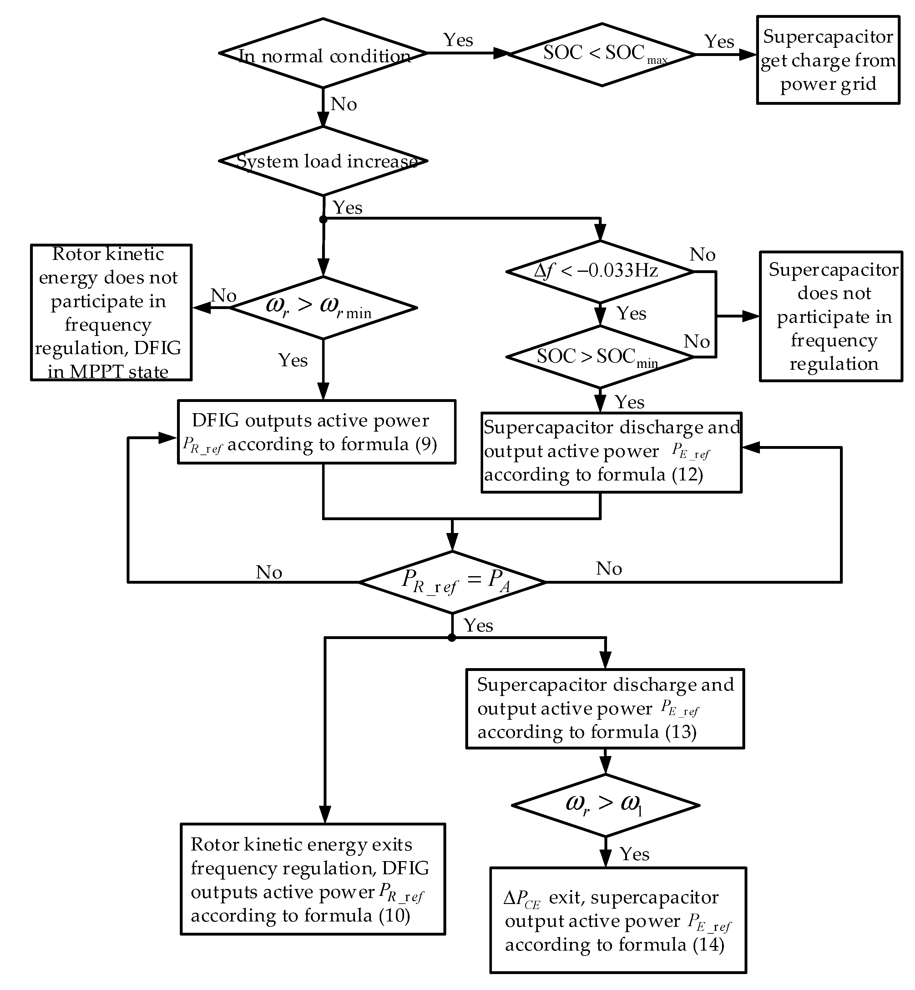
3.3. Control Mode and Flow of Coordinated Frequency Control Strategy for the DFIG and Supercapacitor

As shown in Figure 1, the supercapacitor is connected to the DC bus between the rotor-side converter (RSC) and grid-side converter (GSC) through the bidirectional DC-DC converter [14,36]. By controlling the DC-DC converter, the supercapacitor can discharge and provide its power to the system through the GSC. For the RSC [37], it adopts the control mode of the power outer loop and current inner loop to realize the effective control of the DFIG output power, and the reference value of active power P R _ r e f is shown in Figure 6. For the GSC, it adopts the control mode of the DC voltage outer loop and current inner loop to keep the DC bus voltage stable. For the bidirectional DC-DC converter, its control system includes the power outer loop and current inner loop, which is shown in Figure 8c, and its power reference value P E _ r e f is shown in Figure 7.
In the control strategy, the function of the supercapacitor is to simulate the droop characteristic and compensate the power dip. Compared with the droop characteristic, the time and power used to compensate power dip were shorter and smaller. Therefore, when configuring the capacity of the supercapacitor, the main consideration is droop characteristic. It is stipulated in [6] that when the wind turbine participates in primary frequency regulation, the power regulation shall not exceed 10% rated power and the time is usually 30 s. Therefore, for 1.5 MW DFIG, the capacity of the supercapacitor was set as 150   k W × 30   s . In this capacity, the maximum flow power through GSC is 400 kW [26], which is smaller than the rated power of GSC (480 kW) and meets the power limit of GSC. As for the DC-DC converter, its rated power is usually not less than twice that of the supercapacitor and can be set as 300 kW.
By coordinating the rotor kinetic energy and supercapacitor, it avoids the occurrence of secondary frequency drop, reduces the power loss during rotor speed recovery, and realizes the smooth operation of frequency. The most important is that the DFIG can have an inertia characteristic and droop characteristic like SG. During frequency regulation, the control flow chart of the coordinated frequency control strategy for the DFIG and supercapacitor is shown in Figure 9.
(1) In the normal condition, the system is steady and the DFIG operates at the MPPT state. If the supercapacitor’s state of charge (SOC) is lower than the upper limit, it is charged by the external charging device from the power grid.
(2) When the system frequency decreases caused by load increase, the rotor kinetic energy and supercapacitor will be controlled to participate in frequency regulation. If the rotor speed is higher than the lower limit value 0.7 pu, the rotor kinetic energy of the DFIG will be released to provide inertia support. If the system frequency deviation is greater than 0.033 Hz and the SOC of the supercapacitor is higher than the lower limit, the supercapacitor will control the discharge and release energy to provide drop support.
(3) When the output power of the DFIG itself is equal to the power at steady-state operation point A, rotor kinetic energy exits inertia support and the rotor speed starts to rise. Simultaneously, the supercapacitor still discharges and increases the output active power Δ P C E to compensate the power dip caused by rotor kinetic energy exiting frequency regulation.
(4) In the stage of rotor speed recovery, a new tracking curve E–A of rotor speed and output power is adopted to decrease the output power loss. Simultaneously, the increased part Δ P C E of the supercapacitor exits slowly to prevent the short-time overshoot of system frequency.

4. Simulation Analysis and Research

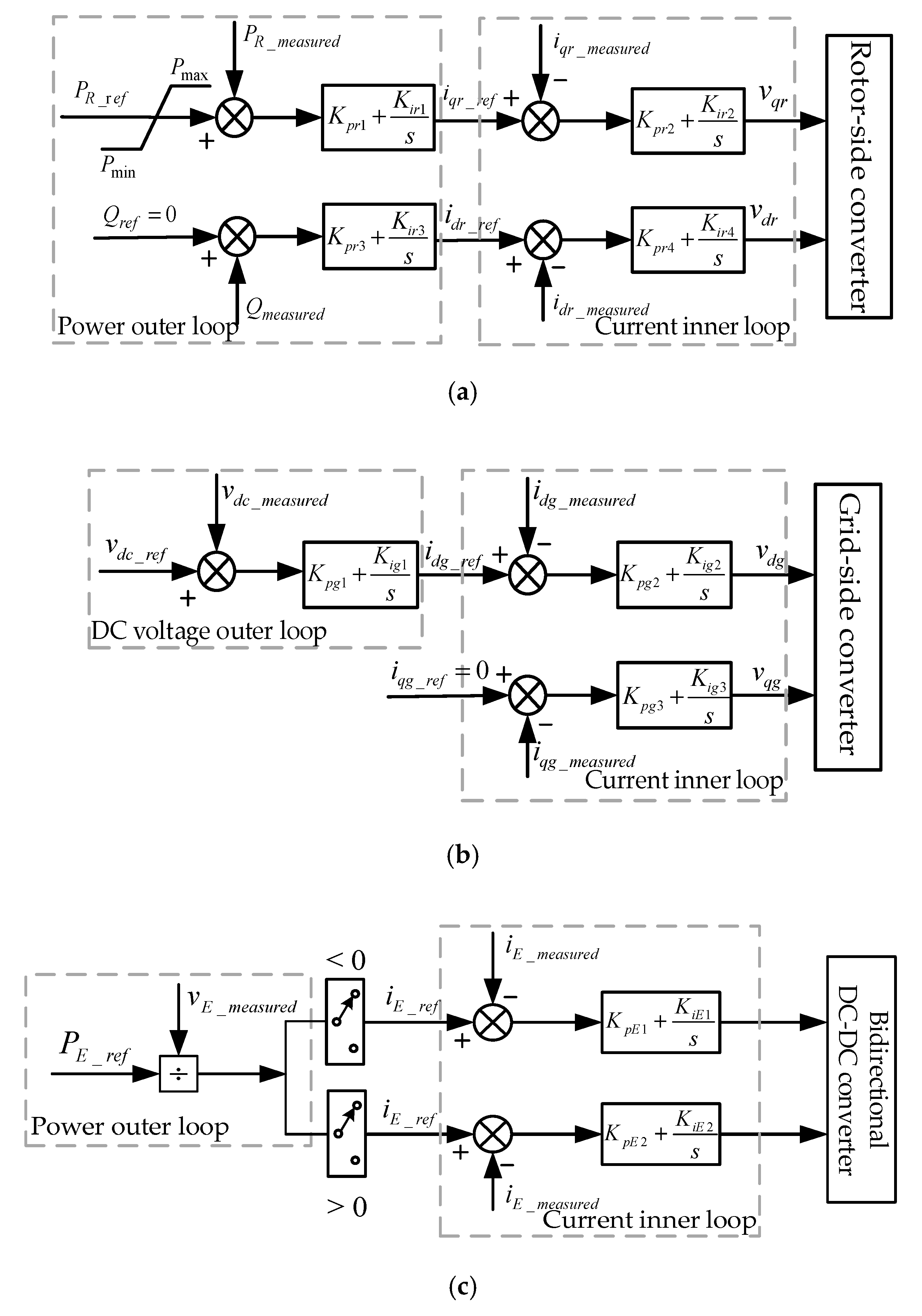
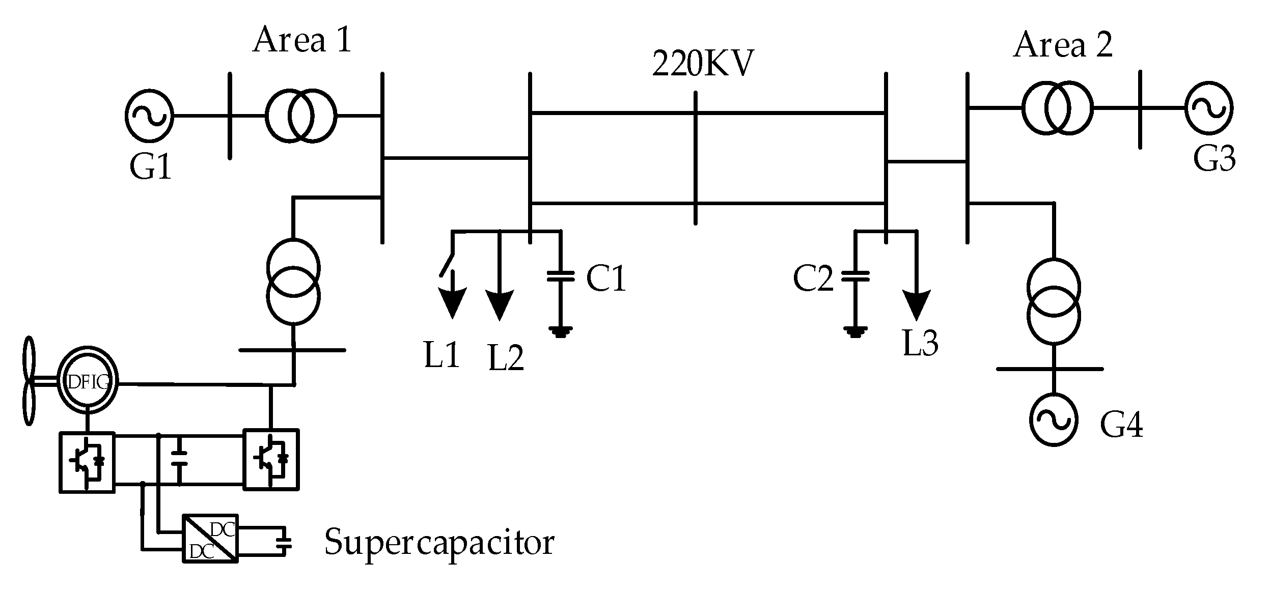
4.1. Simulation Model

In order to verify the correctness of inertia and droop frequency control strategy based on rotor kinetic energy and supercapacitor, a four-machine and two-area model [38] was built in a MATLAB/ SIMULINK simulation platform as shown in Figure 10. The power supply of area one was composed of a SG with a governor and excitation regulator, and 300 DFIG with an energy storage device. The power supply of area two was composed of two SGs. Load L2 and L3 were fixed active loads of 700 MW and 900 MW, and L1 is a removable load of 700 MW. C1 and C2 were reactive compensation devices. The capacity and control parameters of each power supply in the system are shown in Table A1 of the Appendix A.

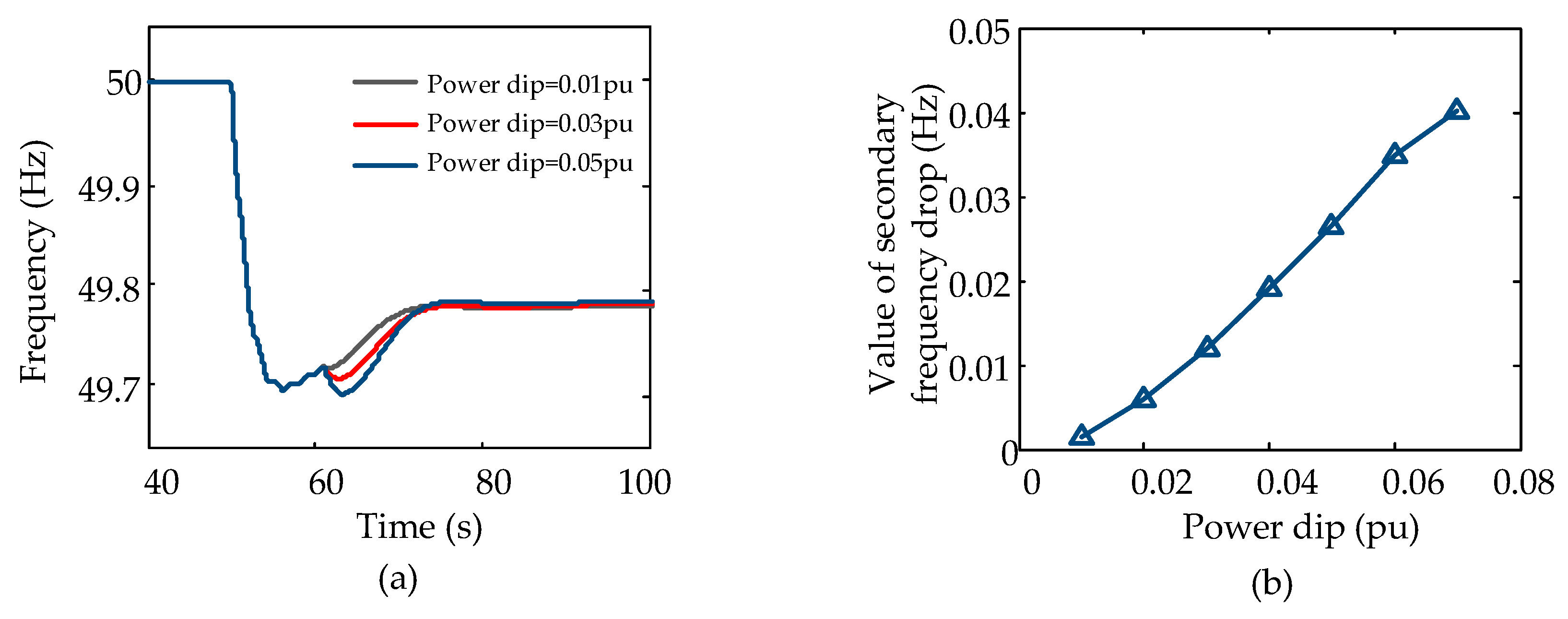
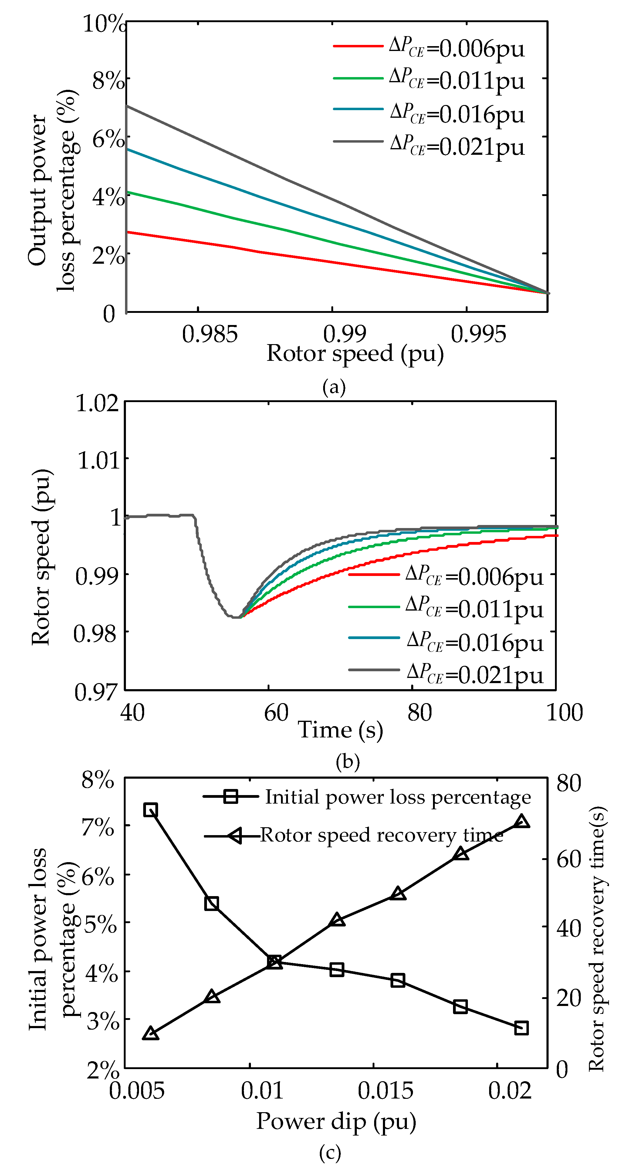
4.2. Selection of Power Dip

The first step of verifying the coordinated frequency control strategy is to determine the value of power dip Δ P C E . When the wind speed is 10 m/s, the rotor speed recovery time and power loss percentage of the DFIG under different power dip values is shown in Figure 11. It can be seen that when Δ P C E was 0.006 pu, the initial power loss percentage was only 2.5%, but the rotor speed recovery time was up to 65 s. When Δ P C E was 0.021 pu, the initial power loss percentage was up to 7.5%, but the rotor speed recovery time only needed 18 s. The two cases were in the extreme state of power loss and recovery time, respectively. From the relationship curve of power dip and power loss percentage in Figure 11c, it can be concluded that the initial power loss percentage increases with the rise in power dip in a fixed proportion. However, the decrease proportion of rotor speed recovery time was large first and then small. If Δ P C E is greater than 0.011 pu, the decrease proportion of rotor speed recovery time will be very small. Therefore, considering the two factors of rotor speed recovery time and output power loss percentage comprehensively, it is more appropriate to select the power dip in the range of 0.011 pu–0.016 pu when the system wind speed is 10 m/s.
The value of power dip under different wind speeds can also be obtained using the above method. Simultaneously, the rotor speed recovery time and initial output power loss percentage can be obtained. The results are shown in Table 2.

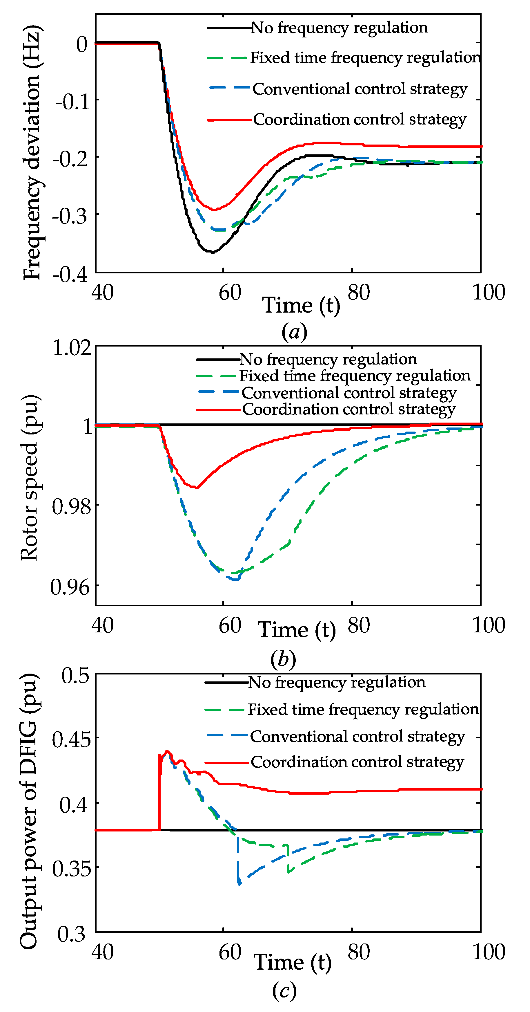
4.3. Analysis of Simulation Results

To prove the superiority of the coordinated control strategy proposed in this paper, a case where a load increase event (removable load L1) triggered at 50 s was simulated when the wind speed was 10 m/s. In this case, the value of power dip Δ P C E was determined as 0.016 pu according to Section 4.2. Additionally, the dynamic response results of system frequency, rotor speed, and output power under conventional control strategy, coordinated control strategy, and the DFIG not participating in frequency regulation are shown in Figure 12. Furthermore, in order to verify the influence of the rotor kinetic energy’s power support time, the fixed time frequency regulation strategy based on conventional control strategy was also simulated. The only difference in the fixed time frequency regulation strategy and conventional control strategy was that the rotor kinetic energy’s support time of the former was longer than the latter. As for the power support time of the fixed time frequency regulation strategy, we selected 20 s in this case.
It can be seen from Figure 12 that the maximum frequency deviation of no frequency regulation was 0.38 Hz. In the conventional control strategy, the maximum frequency deviation was reduced to 0.33 Hz and the frequency change rate was also decreased. However, it had the problem of secondary frequency drop at 64 s, which resulted in the time of frequency returning to stable being prolonged for nearly 10 s. In the fixed time frequency regulation strategy, the secondary frequency drop value was much smaller than the conventional control strategy. However, the time of frequency returning to stability was also longer. The longer time of power support alleviated the secondary frequency drop, but led to the delay of recovering to stable. Furthermore, the steady-state frequency deviation of the conventional control strategy and fixed time strategy were the same as the strategy of the DFIG not participating in frequency regulation, which were all 0.22 Hz.
In the coordinated control strategy based on rotor kinetic energy and the supercapacitor, the maximum frequency deviation was reduced to 0.29 Hz, the steady-state frequency deviation was decreased from 0.22 Hz to 0.19 Hz, and the time of frequency returning to stable was also smaller than that of the conventional control strategy and fixed time strategy. Furthermore, the phenomenon of secondary frequency drop did not occur. This is because the timely exit of rotor kinetic energy ensures the maximum active power output of the DFIG and reduces the maximum frequency deviation. The long-term drop power support of the supercapacitor improves the steady-state value of system frequency. The compensation of the supercapacitor for power dip avoids the phenomenon of secondary frequency drop. Therefore, the coordination control strategy based rotor kinetic energy and supercapacitor effectively improved the dynamic response characteristic of system frequency.
In addition, the simulated result also showed that the rotor speed recovery time of the coordinated control strategy was almost equal to the conventional control strategy, which were both about 25 s. This indicates that the selection of power dip Δ P C E was reasonable. It can be seen from Figure 5 and Figure 11 that the initial power loss percentage of the coordinated control strategy was 5.5%, which was approximately 2/3 lower than the conventional control strategy of 17%. Therefore, it can be concluded that the control scheme proposed in this paper can effectively improve the output active power loss during rotor speed recovery.
For the coordinated control strategy, its inertia support response and droop support response are shown in Figure 13 and Figure 14. It can be seen that the power support time of the DFIG rotor kinetic energy was about 5–6 s and was only used to simulate the inertia characteristic like that of SG. When the output active power of DFIG was smaller than the maximum power before the fault (i.e., 55.4 s), rotor kinetic energy will exit the frequency regulation in time. However, the exit of rotor kinetic energy will cause the output power dip. As for the droop support response of the coordinated control strategy, its power support is from the supercapacitor. It can be seen that the power support time of supercapacitor was longer than the rotor kinetic energy and the output power of the supercapacitor increased at 55.4 s to compensate for the power dip and avoid the secondary frequency drop, gradually decreasing during 55.4 s to 59.8 s to avoid the frequency overshoot. In the coordinated control strategy, the supercapacitor provides primary frequency regulation (primary frequency regulation is generally 30 s) and compensates for the power dip.

5. Conclusions

If the DFIG only relies on rotor kinetic energy to participate in the system frequency regulation, it cannot meet the power grid’s requirements of inertia response and primary frequency regulation. Therefore, the inertia and droop frequency control strategy based on the rotor kinetic energy and supercapacitor was proposed in this paper, which can ensure that the DFIG can provide fast and long-term power support when the frequency fluctuates.
(1) The DFIG contains a lot of rotor kinetic energy, which provides the opportunity for the DFIG to participate in the inertia response. In general, if the rotor speed in steady-state is higher than 0.8 pu, the DFIG has the inertia support capacity of not less than 5 s under 10% rated power. Therefore, the rotor kinetic energy of the DFIG can be used to simulate the inertia response characteristic like the SG.
(2) The supercapacitor has the characteristics of high cycle times, fast charging and discharging speed, and long-time energy supply. Therefore, it can be used to simulate the droop characteristic like the SG and provide primary frequency regulation. Combined with the inertia response characteristic of rotor kinetic energy, it can make DFIG realize the fast and long-time power support when system frequency decreases.
(3) In the coordinated control strategy, the output power mode of the supercapacitor can switch with the DFIG operation state. By controlling the output power of the supercapacitor, it can effectively solve the problem of power dip when the rotor kinetic energy exits inertia support and prevent the phenomenon of secondary frequency drop.
(4) By adopting the new tracking curve of the DFIG rotor speed and output power, the output power loss is effectively alleviated during rotor speed recovery. Furthermore, it can also ensure the maximum output power without prolonging the rotor speed recovery time.

Author Contributions

Conceptualization, X.Y. and X.S.; Methodology, X.Y.; Software, X.S.; Validation, X.S.; Formal analysis, X.Y.; Data curation, X.S.; Writing—original draft preparation, X.S.; Writing—review and editing, X.Y.; Visualization, X.S.; Supervision, X.Y.; Project administration, X.Y.; Funding acquisition, X.Y. All authors have read and agreed to the published version of the manuscript.

Funding

Science and Technology Project of State Grid Corporation of China: SGHEDK00DYJS1900061.

Conflicts of Interest

The authors declare no conflict of interest.

Appendix A

Table A1. Power parameters of the four-machine and two-area system.
Power SupplyParameterValue
DFIGPower1.5 MW
Voltage690 V
stator resistance/reactance0.00706/0.171 pu
rotor resistance/reactance0.005/0.156 pu
magnetizing reactance2.9 pu
inertia constant5.04 s
number of pole pairs3
nominal DC bus voltage1200 V
DC capacitor10 mF
frequency50 Hz
Synchronous generatorPower900 MW
Voltage20 kV
d-axis synchronous/transient/sub-transient reactance1.8 pu/0.3 pu/0.25 pu
q-axis synchronous/transient/sub-transient reactance1.7 pu/0.55 pu/0.25 pu
stator resistance0.0025 pu
Turbine-governorhigh-pressure fraction FH0.3
reheat time constant Tr8 s
droop0.05
governor time constant Tg0.3 s
SupercapacitorPower0.15 MW
Energy0.0075 MWh
Voltage144 V
Capacity55 F
Rotor-side converterpower outer loop: Kpr1 = Kpr31
power outer loop: Kir1 = Kir35
power outer loop: H10.08
current inner loop: Kpr2 = Kpr40.3
current inner loop: Kir2 = Kir48
Grid-side convertervoltage outer loop: Kpg10.002
voltage outer loop: Kig10.05
current inner loop: Kpg2 = Kpg31
current inner loop: Kig2 = Kig3100
Bidirectional DC-DC converterpower outer loop: D10
current inner loop: KpE1 = KpE21.5
current inner loop: KiE1 = KiE21
Filterlow-pass filter TL0.1
high-pass filter TH10

References

  1. Liu, B.; Hu, Y.; Su, W.; Li, G.; Wang, H.; Li, Z. Stability Analysis of DFIG Wind Turbine Connected to Weak Grid based on Impedance Modeling. In Proceedings of the 2019 IEEE Power & Energy Society General Meeting (PESGM), Atlanta, GA, USA, 4–8 August 2019; pp. 1–5. [Google Scholar]
  2. Cai, S.; Wen, H. Modeling and MPPT control of DFIG wind energy system. In Proceedings of the International Conference on Renewable Power Generation (RPG 2015), Beijing, China, 17–18 October 2015; pp. 1–6. [Google Scholar]
  3. Geng, H.; Xi, X.; Yang, G. Small-signal stability of power system integrated with ancillary-controlled large-scale DFIG-based wind farm. IET Renew. Power Gener. 2017, 11, 1191–1198. [Google Scholar] [CrossRef]
  4. Nordel. Nordic Grid Code 2007 (Nordic Collection of Rules) [DB/EB]. 2004. Available online: http://webhotel2.tut.fi/units/set/research/adine/materiaalit/Active%20network/System%20integration/GriG%20codes/Nordel%20grid%20code%202007-00129-01-E.pdf (accessed on 12 April 2020).
  5. Eskom System Operations and Planning Division. Grid code requirements for wind energy facilities connected to distribution or transmission system in south Africa (version 4.4) [DB/EB]. 2012-07. Available online: http://www.nersa.org.za/Admin/Document/Editor/file/Electricity/TechnicalStandards/RSA%20Grid%20Code%20Connection%20Requirements%20for%20Wind%20Energy%20Facilitie.pdf (accessed on 12 April 2020).
  6. National Electric Power Regulatory Standardization Technical Committee. GB/T 19963-2011 Technical Rule for Connecting Wind Farm to Power System[S]; China Standards Press: Beijing, China, 2011. [Google Scholar]
  7. Krpan, M.; Kuzle, I. Dynamic characteristics of virtual inertial response provision by DFIG-based wind turbines. Electr. Power Syst. Res. 2020, 178, 106005. [Google Scholar] [CrossRef]
  8. Pradhan, C.; Bhende, C.N.; Samanta, A.K. Adaptive virtual inertia-based frequency regulation in wind power systems. Renew. Energy 2018, 115, 558–574. [Google Scholar] [CrossRef]
  9. Lee, J.; Muljadi, E.; Srensen, P.; Kang, Y.C. Releasable kinetic energy-based inertial control of a DFIG wind power plant. IEEE Trans. Sustain. Energy 2016, 7, 279–288. [Google Scholar] [CrossRef]
  10. Chen, W.; Wang, J.; Gao, W.; Gao, D.W.; Wang, B.; Wang, H. Power optimization control of doubly fed induction generator based on active power reserve. In Proceedings of the 2016 North American Power Symposium (NAPS), Denver, CO, USA, 18–20 September 2016; pp. 1–6. [Google Scholar]
  11. Chau, T.K.; Yu, S.S.; Fernando, T.L.; Iu, H.H.; Small, M.A. Novel control strategy of DFIG wind turbines in complex power systems for enhancement of primary frequency response and LFOD. IEEE Trans. Power Syst. 2018, 33, 1811–1823. [Google Scholar] [CrossRef]
  12. Vidyanandan, K.V.; Senroy, N. Primary frequency regulation by deloaded wind turbines using variable droop. IEEE Trans. Power Syst. 2013, 28, 837–846. [Google Scholar] [CrossRef]
  13. Arani, M.F.M.; El-Saadany, E.F. Implementing virtual inertia in DFIG-based wind power generation. IEEE Trans. Power Syst. 2013, 28, 1373–1384. [Google Scholar] [CrossRef]
  14. Qu, L.; Qiao, W. Constant power control of DFIG wind turbines with supercapacitor energy storage. IEEE Trans. Ind. Appl. 2011, 47, 359–367. [Google Scholar] [CrossRef] [Green Version]
  15. Liu, J.; Yao, W.; Wen, J.Y. A wind farm virtual inertia compensation strategy based on energy storage system. Proc. CSEE 2015, 35, 1596–1605. [Google Scholar]
  16. Mamen, A.; Supatti, U. A survey of hybrid energy storage systems applied for intermittent renewable energy systems. In Proceedings of the 2017 14th International Conference on Electrical Engineering/Electronics, Computer, Telecommunications and Information Technology (ECTI-CON), Phuket, Thailand, 27–30 June 2017; pp. 729–732. [Google Scholar]
  17. Jiang, Q.Y.; Gong, Y.Z. Review of wind power integration control with energy storage technology. Power Syst. Technol. 2015, 39, 360–3368. [Google Scholar]
  18. Krpan, M.; Kuzle, I. Coordinated Control of an Ultracapacitor Bank and a Variable-Speed Wind Turbine Generator for Inertial Response Provision During Low and Above Rated Wind Speeds. In Proceedings of the 2019 IEEE Sustainable Power and Energy Conference: Grid Modernization for Energy Revolution, Beijing, China, 21–23 November 2019; pp. 1693–1698. [Google Scholar]
  19. Sun, D.; Sun, L.; Wu, F.; Zhang, L.; Geng, W.; Peng, J.; Liu, F. Research on frequency inertia response control strategy of SCESS-DFIG system considering variable wind speed. J. Eng. 2019, 2995–3001. [Google Scholar] [CrossRef]
  20. Xiong, L.; Li, Y.; Zhu, Y.; Yang, P.; Xu, Z. Coordinated control schemes of super-capacitor and kinetic energy of DFIG for system frequency support. Energies 2018, 11, 103. [Google Scholar] [CrossRef] [Green Version]
  21. Kim, J.; Muljadi, E.; Gevorgian, V.; Hoke, A.F. Dynamic capabilities of an energy storage-embedded DFIG system. IEEE Trans. Ind. Appl. 2019, 55, 4124–4134. [Google Scholar] [CrossRef]
  22. Miao, L.; Wen, J.Y.; Xie, H.L. Coordinated control strategy of wind turbine generator and energy storage equipment for frequency support. IEEE Trans. Ind. Appl. 2015, 54, 2732–2742. [Google Scholar] [CrossRef]
  23. Zhao, J.J.; Li, M.; He, X.Q. Coordinated control strategy of wind power and energy storage in frequency regulation based on torque limit control. Trans. China Electrotech. Soc. 2019, 34, 4982–4990. [Google Scholar]
  24. Yuan, T.J.; Wang, J.J.; Guan, Y.H.; Liu, Z.; Song, X.; Che, Y.; Cao, W. Virtual inertia adaptive control of a Doubly Fed Induction Generator (DFIG) Wind Power System with Hydrogen Energy Storage. Energies 2018, 11, 904. [Google Scholar] [CrossRef] [Green Version]
  25. Xu, T.; Jang, W.; Overbye, T. Commitment of fast-responding storage devices to mimic inertia for the enhancement of primary frequency response. IEEE Trans. Power Syst. 2018, 33, 1219–1230. [Google Scholar] [CrossRef]
  26. Yan, X.W.; Song, Z.J.; Cui, S. Primary frequency regulation strategy of doubly-fed wind turbine based on variable power point tracking and supercapacitor energy storage. Trans. China Electrotech. Soc. 2020, 35, 530–541. [Google Scholar]
  27. Xie, D.; Feng, J.Q. Small-signal modelling and modal analysis of DFIG-based wind turbine based on three-mass shaft model. Proc. CSEE 2013, 33, 21–29. [Google Scholar]
  28. Liu, B.B.; Yang, J.W.; Liao, K. Improved frequency control strategy for DFIG-based wind turbine based on rotor kinetic energy control. Autom. Electr. Power Syst. 2016, 40, 17–22. [Google Scholar]
  29. Chen, Y.H.; Wang, G.; Shi, Q.M. A new coordinated virtual inertia control strategy for wind farms. Autom. Electr. Power Syst. 2015, 39, 27–33. [Google Scholar]
  30. Liu, H.; Ge, J.; Gong, Y. Wind farm participation in grid primary frequency optimization scheme selection and wind storage coordination control strategy research. Glob. Energy Internet 2019, 2, 44–52. [Google Scholar]
  31. Kulsangcharoen, P.; Klumpner, C.; Rashed, M.; Asher, G. A new duty cycle based efficiency estimation method for a supercapacitor stack under constant power operation. In Proceedings of the 5th IET International Conference on Power Electronics, Machines and Drives (PEMD 2010), Brighton, UK, 19–21 April 2010; pp. 1–6. [Google Scholar]
  32. Yang, H. Supercapacitor energy delivery capability during a constant power discharge process. In Proceedings of the IECON 2018-44th Annual Conference of the IEEE Industrial Electronics Society, Washington, DC, USA, 21–23 October 2018; pp. 1958–1963. [Google Scholar]
  33. Du, Y.; Zhang, A.; Zhang, Y. The design and implementation of supercapacitor charging device and monitor system for electrical trams. In Proceedings of the 2018 Chinese Control and Decision Conference (CCDC), Shenyang, China, 9–11 June 2018; pp. 5893–5897. [Google Scholar]
  34. Tahtawi, A.R.A.; Rohman, A.S. Simple supercapacitor charging scheme in electrical car simulator by using direct current machines. In Proceedings of the 2015 International Conference on Electrical Engineering and Informatics (ICEEI), Denpasar, Indonesia, 10–11 August 2015; pp. 562–567. [Google Scholar]
  35. Lawu, B.L.; Fuada, S.; Ramadhan, S.; Sabana, A.F.; Sasongko, A. Charging supercapacitor mechanism based-on bidirectional DC-DC converter for electric ATV motor application. In Proceedings of the 2017 International Symposium on Electronics and Smart Devices (ISESD), Yogyakarta, Indonesia, 17–19 October 2017; pp. 129–132. [Google Scholar]
  36. Boubzizi, S.; Abid, H.; Ahmed, E.H.; Mohamed, C. Comparative study of three types of controllers for DFIG in wind energy conversion system. Protect. Control Mod. Power Syst. 2018, 3, 214–225. [Google Scholar] [CrossRef]
  37. Tummala, S.; Ayyarao, L.V. Modified vector controlled DFIG wind energy system based on barrier function adaptive sliding mode control. Protect. Control Mod. Power Syst. 2019, 4, 34–41. [Google Scholar]
  38. Yan, X.; Song, Z.; Xu, Y.; Sun, Y.; Wang, Z.; Sun, X. Study of Inertia and Damping Characteristics of Doubly Fed Induction Generators and Improved Additional Frequency Control Strategy. Energies 2018, 12, 1. [Google Scholar] [CrossRef] [Green Version]
Figure 1. Configuration schematic of the inertial and droop coordination control strategy.
Energies 13 03697 g001
Figure 2. Block diagram of the conventional frequency control based on rotor kinetic energy.
Energies 13 03697 g002
Figure 3. Tracking curve of the doubly-fed induction generator (DFIG) power and rotor speed.
Energies 13 03697 g003
Figure 4. Secondary frequency drop under different power dip: (a) System frequency under different power dip; (b) Relationship between power dip and secondary frequency drop.
Energies 13 03697 g004
Figure 5. Output active power loss during rotor speed recovery. (a) Relationship between rotor speed and output active power loss. (b) Relationship between rotor speed and power loss percentage.
Energies 13 03697 g005
Figure 6. Control block diagram of the DFIG rotor kinetic energy.
Energies 13 03697 g006
Figure 7. Control block diagram of the supercapacitor.
Energies 13 03697 g007
Figure 8. Control mode of the coordinated frequency control strategy for the DFIG and supercapacitor. (a) Rotor-side converter control model; (b) Grid-side converter control model; (c) Bidirectional DC-DC converter control model.
Energies 13 03697 g008
Figure 9. Flow chart of the coordinated frequency control strategy for the DFIG and supercapacitor.
Energies 13 03697 g009
Figure 10. Simulation system model of four-machine and two-area.
Energies 13 03697 g010
Figure 11. Relationship between rotor speed and power loss under different power dip: (a) Output power loss percentage during rotor speed recovery; (b) Rotor speed recovery curve under different power dip; (c) Rotor speed recovery time and initial power loss percentage under different power dip.
Energies 13 03697 g011
Figure 12. System dynamic response under different control strategies. (a) System frequency deviation; (b) Rotor speed of the DFIG; (c) Output power of the DFIG.
Energies 13 03697 g012
Figure 13. Power difference between the DFIG and supercapacitor.
Energies 13 03697 g013
Figure 14. Output active power of the supercapacitor.
Energies 13 03697 g014
Table 1. Inertia support capacity of the doubly-fed induction generator (DFIG) at different rotor speed.
Rotor Speed
( r . min 1 )
Rotor Kinetic Energy(MJ)Power Support Time Under 10% Rated Power(s)
1800 (1.2 pu)9.978.79 s
1500 (1 pu)5.358.36 s
1350 (0.9 pu)3.367 s
1200 (0.8 pu)1.576.02 s
Table 2. Value of power dip at different wind speeds.
Wind Speed
(m/s)
Δ P C E ( pu ) Rotor Speed Recovery Time (s)Initial Power Loss Percentage (%)
80.016–0.01932–267.1–9
90.012–0.016731–255.3–6.95
100.011–0.01627–21.54.1–5.5
110.010–0.01532–262.2–3.7

