1. Introduction
The survival and development of human beings have a close relationship with energy. With the development of the world, human beings are faced with the contradiction between the increase of energy demand and the decrease of existing fossil energy. With the purpose of reducing fossil energy consumption and its operating cost, together with mitigating pollution of the environment, the concept of electric aircraft emerges and substantial efforts have been made in this area [
1].
As shown in
Table 1, a comparison is made between a traditional aircraft and three types of electric aircraft. The engine of a traditional aircraft is an internal combustion engine, while the engine of an electric aircraft is an electromotor. The weight of an internal combustion engine is about seven times that of an electromotor, thus the electric aircraft can more effectively control the flight attitude due to the reduction of weight. In addition, because the electromotor of an electric aircraft does not need a throttle valve to control the intake pressure and the fuel intake, the high torque of the electromotor can be directly transmitted to the propeller without energy consumption, which is beneficial to reducing losses and improving the efficiency [
2]. The three types of electric aircraft are fuel cell aircraft, supercapacitor aircraft, and photovoltaic (PV) aircraft. Compared with natural gas and gasoline, hydrogen is the best fuel for fuel cells, which causes little pollution to the environment, but the production cost of hydrogen is much higher than that of traditional fossil fuel [
3]. Supercapacitors have both the characteristics of fast charge and discharge of capacitors and the energy storage characteristics of batteries, but their efficiencies are greatly affected by the temperature and operating voltage [
4]. PV aircraft uses PV panels to convert solar energy into electricity. A PV panel is a type of power generation device made of semiconductor materials that can generate direct current when exposed to sunlight. Using PV panels to generate electricity is simple, convenient and effective. Compared with other types of aircraft, PV aircraft gets rid of dependence on traditional fossil energy and does not pollute the environment. There is no doubt that the concept of low-carbon environmental protection triggered by PV aircraft is the future developing trend [
5].
Considering the safety of aircraft, three types of electrical machines applied on aircraft have developed rapidly in recent years, which are the induction motors (IMs), permanent magnet synchronous motors (PMSMs), and switched reluctance motors (SRMs) [
6]. An IM is also called an asynchronous motor. The rotor of IMs obtains a rotating torque and starts to rotate under the action of a rotating magnetic field. IMs have low moment of inertia and simple rotor structure, which can run for a long time under high temperature and high speed conditions. However, the power factor and efficiency of IMs are low, and the loss of an IM rotor is large [
7]. A PMSM is a synchronous motor that generates a synchronous rotating magnetic field by the excitation of a permanent magnet. The permanent magnet acts as a rotor to generate a rotating magnetic field. PMSMs are widely used in electric aircraft due to their high power density, high efficiency, fast dynamic response, and high torque. However, the tensile strength of PMSMs is small, the rotor of PMSMs is prone to encounter irreversible demagnetization at high temperature, and the manufacturing cost of PMSMs is high [
8]. The speed control system of SRMs is considered to be the latest generation of speed control system after variable frequency speed control system and brushless direct current motor speed control system, because SRMs have the advantages of high efficiency, robustness, low manufacturing cost, high speed performance, and inherent fault tolerance. The high torque and small current during the starting process make SRMs suitable for the operation of PV aircraft [
9,
10].
In an SRM drive, the most widely used power converter is the asymmetric half-bridge topology (AHT). However, SRMs need some more practical power converter structures in different fields and actual requirements. In [
11,
12,
13,
14,
15], the topology was improved with many new topologies proposed in order to adapt to various situations. The design ideas and research methods of these topologies proposed in [
11,
12,
13,
14,
15] play an important role in promoting the research of this paper. The driving system designed in [
11] can improve the performance of the motor, but PV panels and the generator control unit are connected in parallel; the voltage is forced to change, which is not conducive to improving the stability of the system. Paper [
12] proposed a converter that uses additional inductance to increase the output torque and demagnetization voltage, but the efficiency and the power density are reduced. Improving the commutation voltage and torque capacity becomes the research direction of this paper. Paper [
13] proposed a modular multilevel converter-based SRM drive with a decentralized battery-energy-storage system for hybrid electric vehicle applications. In the proposed drive, a battery pack and a half-bridge converter are connected as a submodule, and multiple submodules are connected. However, the bus voltage is reduced, and the excitation and demagnetization processes are slowed, which are not conducive to improving system efficiency. Paper [
14] developed a three-level converter to reduce the number of current rises and falls, but twice as many power transistors as those in an AHT are needed. Paper [
15] proposed an integrated multilevel converter of SRMs fed by a modular front-end circuit for plug-in hybrid electric vehicle applications. Several operating modes can be achieved by changing the on–off states of the switches in the front-end circuit. This paper designs the multiport power source module, which accelerates the excitation and demagnetization process, and improves the torque capacity and efficiency by generating multilevel voltage.
This paper proposes a multiport driving topology (MDT) drive for SRM that is connected to PV panels and a battery pack in order to achieve multiport source operation, adapt to complex weather conditions, and improve the motoring performance. The PV panels and battery pack can achieve three driving and two charging modes according to different conditions. PV panels use sustainable solar energy for the power supply, which is clean and pollution-free, thus the flexible combination of battery pack and PV panels can also overcome the environmental limitations and extend the mileage. The SRM system powered by PV panels and battery packs can achieve multilevel commutation voltages, which can accelerate the excitation and demagnetization process, and improve the torque capacity. The battery pack can be directly charged by the motor windings or can absorb demagnetization current during operation to reduce losses. The battery pack, PV panels, and the asymmetric half-bridge circuit form a compact and integrated converter topology. In this integrated driving mode, this new MDT reduces the complexity of the circuit board and power loss, and it improves the system efficiency and the output torque. However, the conversion rate of PV panels and the energy density of the battery pack are relatively low, and this is where improvement is needed.
2. Multiport Driving Topology for a Photovoltaic Aircraft
2.1. Switched Reluctance Motor
In order to avoid the short-circuit faults of the bridge arm, the phase winding of the SRM is directly connected in series between the two switching devices. This paper chooses the Pulse Width Modulation (PWM) control method and the nonenergy feedback chopper method [
16,
17]. The phase current continues to flow in the zero-voltage loop during the chopper freewheeling period to avoid the exchange of reactive energy between the SRM and the power source, which is beneficial to increase the torque and the utilization capacity of power converter, reduce the number of chopping and torque ripples, and suppress the power supply voltage fluctuation [
18,
19].
Without considering the iron loss and mutual inductance between phase windings, the electromechanical energy conversion of the SRM system is analyzed in detail [
20,
21]. The voltage of phase K is expressed as follows:
where
Uk is the phase K supply voltage,
Rk is the phase K resistance,
ik is the phase K current,
Lk is the phase K inductance,
Ψk is the phase K magnetic flux, and
ϴk is the rotor position angle.
The magnitude of the current is directly proportional to the supply voltage and inversely proportional to the motor speed when the turn-on and turn-off angles are fixed [
22]. Therefore, increasing the excitation voltage at the beginning can accelerate the formation of the excitation current to achieve rapid excitation [
23]. The braking torque is generated when the freewheeling current flows through the area where the inductance drops. Therefore, the demagnetization process can be accelerated by increasing the demagnetization voltage [
24].
2.2. Multiport Driving Topology
For the traditional SRM power converter, stable speed regulation can be achieved in a wide range by applying a fixed voltage. However, a PV aircraft faces complex and changeable weather conditions, and the multiport power source control of PV panels and the battery pack is complicated. Therefore, an MDT is designed in this paper, which uses PV panels and a battery pack to achieve multistage speed regulation in three driving modes, as shown in
Figure 1.
As shown in
Figure 2, a PV aircraft has three driving modes and two charging modes. The three driving modes are the SRM system powered by the PV panels, battery pack, and both together. The two charging modes are self-charging mode and static charging mode.
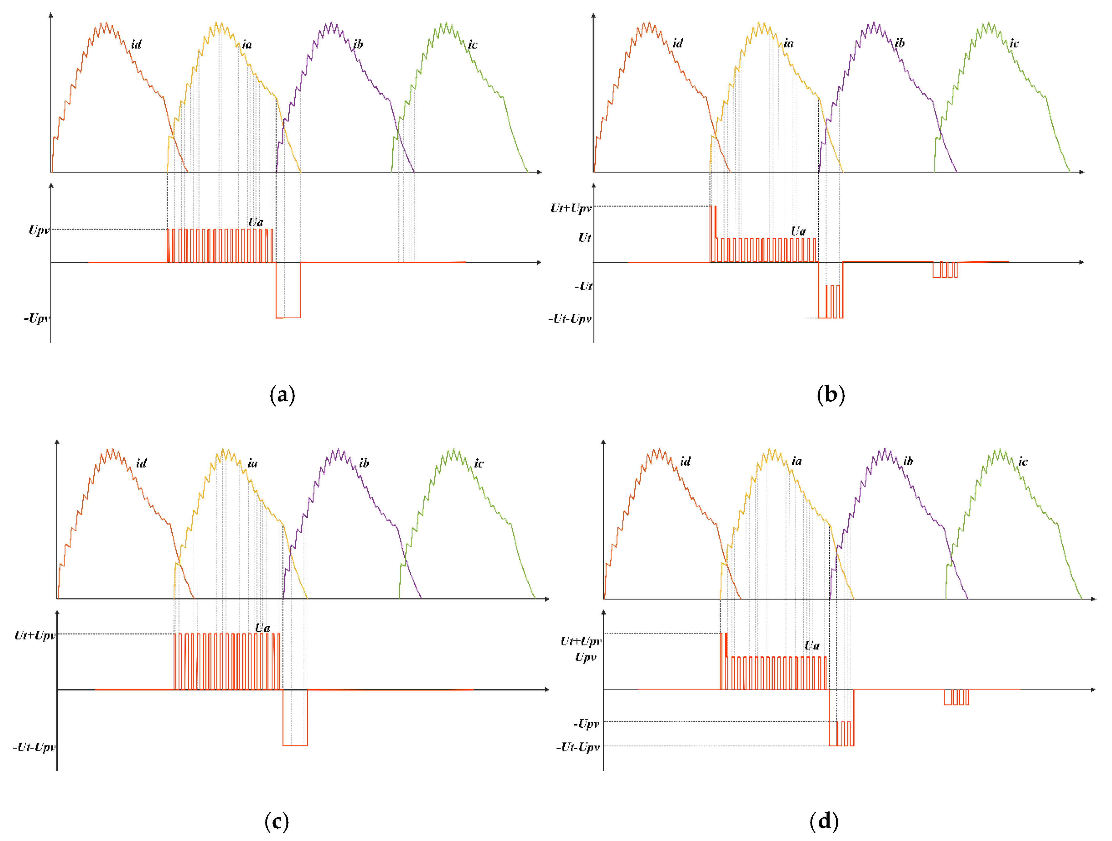
Figure 3 presents the relationship between the phase voltage and phase current. In the three driving modes, the process of excitation and demagnetization is accelerated because the initial excitation voltage and demagnetization voltage are increased, and the output torque is improved. When the SRM system is powered by the PV panels and battery pack together, the commutation voltage is improved compared to that in the traditional SRM system driven by the AHT, as shown in
Figure 3a,c. Although PV panels are not directly involved in the power supply, the PV panels help to increase the excitation and demagnetization voltage when the SRM system is powered by a battery pack, as shown in
Figure 3b. The battery pack can also increase initial excitation and demagnetization voltage when the SRM system is powered by PV panels, as shown in
Figure 3d.
2.3. Analysis of MDT in Three Driving Modes
Mode 1: When the aircraft is powered by the battery pack, switch
S9 is turned on and switch
S10 is turned off. PV panels can help increase the commutation voltage, as shown in
Figure 3b. When the solar power is insufficient, the PV panel voltage is zero, so the working condition of SRM is similar to the traditional mode.
When
ϴon <
ϴ <
ϴoff, the excitation process of the SRM system powered by the battery pack is shown in
Figure 4. The phase current changes are mainly presented by three stages.
When the phase D freewheeling current is larger than the phase A current, the phase D freewheeling current not only flows through the battery pack and the energy storage capacitor C
2, but also flows through phase A to help it form the exciting current, as shown in
Figure 4a. The phase A and phase D voltages are expressed as follows:
where
Ut is the battery pack voltage,
Upv is the PV panel voltage,
Ua is the phase A voltage,
Ud is the phase D voltage,
Ra is the phase A resistance,
ia is the phase A current,
La is the phase A inductance,
ϴa is the rotor position angle of phase A, and
ωr is the rotor angular velocity.
When the phase D freewheeling current is smaller than the phase A current, or phase D has finished the freewheeling stage, it cannot help phase A to form the exciting current, as shown in
Figure 4b. The voltage of phase A is expressed as follows:
Figure 4c shows the chopper freewheeling stage. The voltage of phase A is expressed as follows:
When
ϴoff <
ϴ < 2
ϴoff − ϴon, the demagnetization process of the SRM system powered by the battery pack is shown in
Figure 5. The current changes are mainly presented by four stages.
When phase A starts the demagnetization process while phase B has not yet started the excitation process, the phase A freewheeling current is not related to phase B, as shown in
Figure 5a. The voltage of phase A is expressed as follows:
When phase B starts the excitation process and the phase A freewheeling current is larger than the phase B current, the phase A freewheeling current helps phase B to establish the excitation current, and the demagnetization voltage of phase A does not change, as shown in
Figure 5b. The voltage of phase A is expressed as follows:
When phase A continues to be in the freewheeling stage and the phase A freewheeling current is smaller than the phase B current, the phase A freewheeling current is not large enough to help phase B to establish the exciting current. In this case, the battery pack helps phase B to establish the exciting current, and the phase A voltage starts to change, as shown in
Figure 5c. The phase A and phase B voltages are expressed as follows:
when the phase A freewheeling current flows through the phase B PWM chopper freewheeling stage, because phase B is in a zero-voltage loop, the phase A freewheeling current is larger than the phase B current, and the phase A demagnetization voltage returns to the original voltage, as shown in
Figure 5d. The phase A and phase B voltages are expressed as follows:
When
ϴ > 2
ϴoff−
ϴon, phase B or phase C is in the freewheeling stage, because the voltage of each phase freewheeling is a pulsed alternating voltage, which is different from the single-level voltage of the SRM system driven by the AHT. The phase A windings will generate a small induced current, and the phase A voltage will start to change. The voltage of phase A is expressed as follows:
Mode 2: When the aircraft is powered by the PV panels and battery pack together, switches
S9 and
S10 are turned on. The operation mode is similar to the traditional mode, but the excitation and demagnetization voltages are always high, as shown in
Figure 3c and
Figure 6.
When phase A is in the excitation stage, the voltage of phase A is expressed as follows:
When phase A is in the chopper freewheeling stage, the voltage of phase A is expressed as follows:
When phase A is in the freewheeling stage, the voltage of phase A is expressed as follows:
Mode 3: When the aircraft is powered by the PV panels, switch
S9 is turned off and switch
S10 is turned on. The working stages are similar to the SRM system powered by the battery pack, and the difference is that PV panels act as a power source instead of the battery pack, and the magnitude of the phase voltage is different, as shown in
Figure 3d.
After the above analysis, the initial excitation and demagnetization voltages are increased during the operation process of the aircraft. Excitation and demagnetization processes are accelerated and the efficiency is improved. The multilevel commutation voltage is achieved in mode 2 and mode 3.
2.4. Analysis of Efficiency and Power Density
The SRM input power transfer function is as follows:
The SRM output power transfer function is as follows:
The SRM efficiency transfer function is as follows:
where
η is the SRM efficiency,
Pin is the SRM input power,
Pout is the SRM output power,
Nr is the number of rotor poles,
Us is the excitation voltage,
Is is the bus current,
Tav is the SRM average torque.
The SRM power density transfer function is as follows:
where
S is the SRM power density and
VM is the SRM characteristic volume.
The input power of the SRM is converted into the magnetic field storage of the winding and mechanical power output. The battery pack or PV panels can increase the excitation voltage at the beginning of the excitation stage, but it does not power the system, so the input power of the system does not change significantly. When
ωr,
ϴon, and
ϴoff are fixed, the output power can be increased by increasing the output torque, and the increase of output power can help improve the system efficiency and the power density.
When the phase winding is energized in the rising region of the phase inductance, the rotating electromotive force is positive and the SRM generates positive electric torque. Otherwise, when the phase winding is energized in the area where the phase inductance drops, the rotating electromotive force is negative and the SRM generates braking torque.
where
Te is the total electromagnetic torque,
Tl is the load torque,
J is the total inertia moment of the motor and the load, and
μ is the combined friction coefficient of the motor and the load.
Positive and negative torques can be obtained by controlling the phase current in the rising or falling region of the inductance, respectively. When the excitation voltage is low, the current rises slowly and a negative torque is easily generated due to the excitation current existing in the area where the inductance decreases, which is not conducive to improving the performance of the motor. However, this negative torque can be eliminated by increasing the excitation and demagnetization voltages. A constant DC power source cannot achieve a multilevel voltage, so the output torque is limited during high-speed operation.
Compared with the AHT, the excitation voltage of the MDT system increases at the beginning of excitation, and the rise time of phase current in the minimum inductance region is prolonged, which increases the current entering the effective working area. The output torque and demagnetization voltage are increased, the demagnetization stage is accelerated, the braking torque is avoided or reduced, and the output torque of the system is improved.
2.5. Charging Modes of the Battery Pack
There are two battery charging modes: self-charging mode and static charging mode. The self-charging mode is mainly in the freewheeling stage. Because the freewheeling current is small, its main role is to reduce the power consumption. The PV panels charge the battery pack when the static charging mode is applied, which can get rid of the dependence on fossil fuels and traditional power grids, reducing the cost and environmental pollution.
Self-charging mode: When the SRM is in operation, taking phase A as an example, and S1 and S2 are turned off, the phase current will be fed back to the battery pack through the freewheeling diode. This regenerative effect results in a higher efficiency for the SRM. When the SRM system is powered by the PV panels, the battery pack does not participate in the excitation process, but receives the current feedback during the freewheeling stage. When the battery pack participates in the excitation process, it also can receive the current feedback during the freewheeling stage.
Static charging mode: When the SRM is in standstill, the battery pack is charged by the PV panels. Because the power level of the PV panels is relatively low, only one phase winding is required to be charged. Take phase A as an example; switch
S9 is turned off, switch
S10 is turned on, switches
S1,
S2 are turned on, and the switches in the other phases are turned off. Phase A windings are equivalent to inductors, and the PV panels provide energy to them, as shown in
Figure 7a. Then switches
S1 and
S2 are turned off to feed the current in the phase winding back to the battery pack, as shown in
Figure 7b. The charging current can be easily controlled by controlling the duty cycle of switches
S1 and
S2, along with the switch PWM frequency of phase A.
The winding current of phase A is expressed as follows:
where
ia0 is the initial phase current,
iam is the maximum phase current,
D is the duty cycle of switch
S1 and switch
S2, and
T is the switching period.
The battery pack charging current of phase A is expressed as follows:
3. Simulation Results
In order to verify the feasibility of MDT, an SRM system model was built in simulation. The parameters of the model are shown in
Table 2.
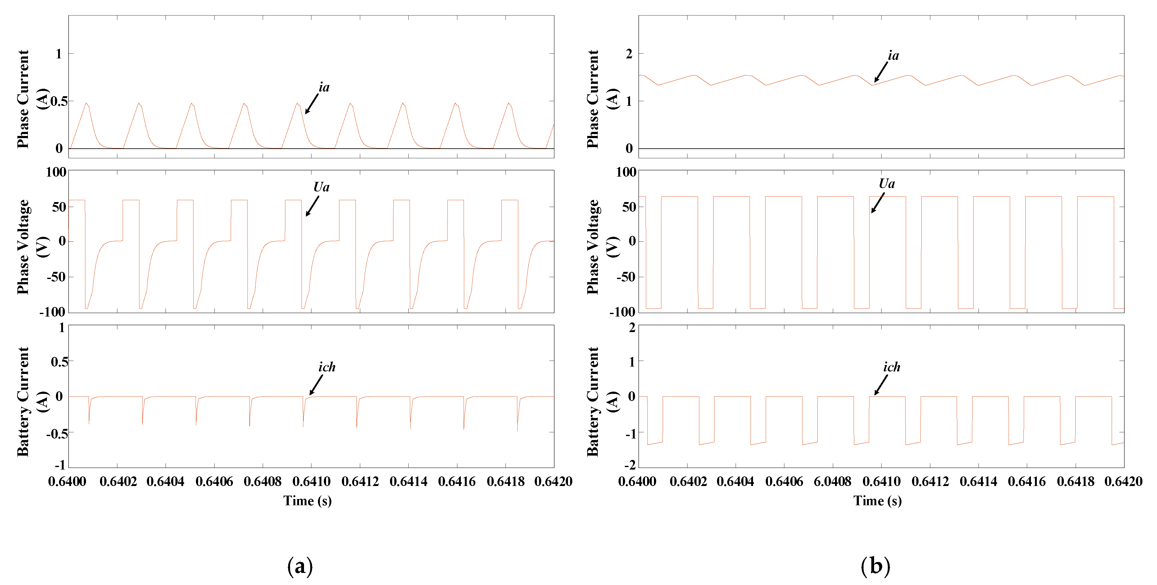
Figure 8 presents the simulation waveforms of the proposed motor drive operating at 600 rpm, where
ia,
ib,
ic, and
id are the phase currents of phase A, B, C and D, respectively,
Ua is the phase A winding voltage,
ibus is the bus current,
it is the battery pack current, and
ich is the battery pack charging current.
The excitation and demagnetization voltages are both single-level voltages when the SRM is powered by PV panels and driven by the traditional AHT, as shown in
Figure 8a. The PV panels do not participate in the excitation process when the SRM is powered by the battery pack, but the excitation and demagnetization voltages are both increased, which accelerates the excitation and demagnetization processes. The efficiency is improved due to the presence of multilevel voltage during the commutation process, and the freewheeling current flows through the battery pack to charge the battery, as shown in
Figure 8b. The commutation voltage is increased when the SRM is powered by the PV panels, as shown in
Figure 8d, where the working modes are similar to those in
Figure 8b. The working modes of the SRM powered by the PV panels and battery pack together are similar to the SRM powered by the traditional AHT, and the difference is that the excitation and demagnetization processes maintain a high voltage level, which can accelerate the excitation and demagnetization processes, avoid braking torque, and increase the electromagnetic torque, as shown in
Figure 8c. The self-charging mode can reduce the power consumption when the SRM system is running.
Figure 9 presents the static charging mode with the duty cycles of 30% and 70%. The charging current can be changed by controlling the duty cycles of the phase switches, and the charging current can be increased by increasing the duty cycle.
Figure 10 presents the comparisons of the average torque, efficiency, and output torque when the speed is changed from 600 to 900 r/min between the traditional drive mode by employing the AHT and the proposed drive mode by employing the proposed MFT, where
Tav is the average torque,
ղ is the system efficiency, and
n is the system speed. The traditional drive mode is powered by a 60 V DC source, the proposed drive mode is powered by the 60 V PV panels, switch
S9 is turned off and switch
S10 is turned on. As shown in
Figure 10, the average torque and output torque are increased due to the acceleration of the excitation and demagnetization processes, and the efficiency is slightly improved due to the increase of output torque. The proposed drive mode can make the speed and torque stabilize more quickly when the speed is changed from 600 to 900 r/min.
4. Experimental Verification
A 500 W SRM converter is experimentally verified with the same parameters as those used in the simulation, and the experimental platform is shown in
Figure 11. The SRM is driven by MDT, which is established with the insulated gate bipolar transistor (IGBT) connected with a fast recovery antiparallel diode to drive the motor. PV panels are simulated by using an adjustable 46 V DC power source, and three batteries are connected in series to form a 36 V battery pack. The rotor position is determined by a 1000-line incremental encoder. The main control system is implemented by the TMS320F28335 digital signal processor produced by Texas Instruments. A Hall effect current sensor is used to collect the phase current signal.
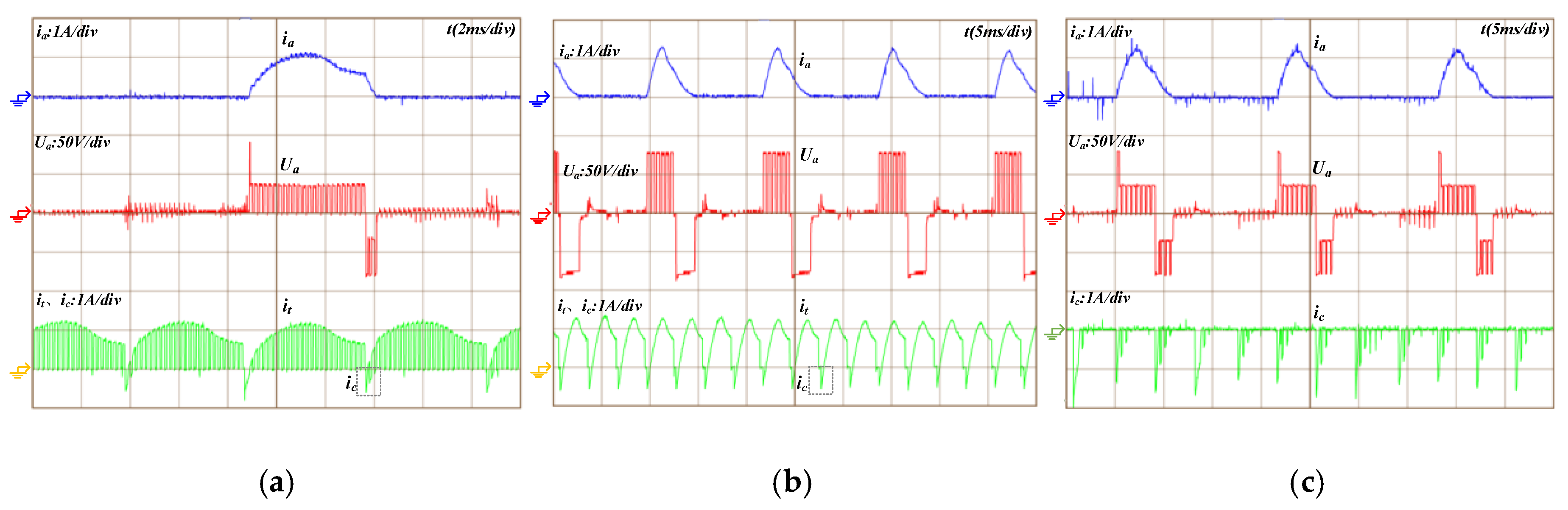
Figure 12 presents the experimental waveforms of the proposed motor drive operating at 600 rpm and 0.8 N · m, where
ia is the phase A current,
Ua is the phase A winding voltage (the battery pack current), and
ic is the battery pack charging current. The excitation voltage and demagnetization voltage are both increased to accelerate the excitation and demagnetization processes. Multilevel voltage appears during commutation, as shown in
Figure 12a,c. The excitation and demagnetization processes maintain high voltage level when the SRM is powered by the PV panels and battery pack together, as shown in
Figure 12b.
Figure 13 presents the experimental waveforms of charging in the static charging mode with the duty cycles of 30% and 70%. The charging current can be changed by controlling the duty cycle of the phase A switches, and the charging current becomes larger with the increase of duty cycle.
5. Conclusions
In this paper, the MDT for a PV aircraft driven by SRMs is proposed, which not only improves the performance of the aircraft system in the operating condition, but also implements flexible charging functions. The multilevel voltage is obtained and the efficiency is improved. Compared with traditional converters, the MDT can increase the excitation voltage to speed up the establishment of phase current and increase the demagnetization voltage to speed up the demagnetization process, which can increase the output torque, output power, efficiency, and power density. Compared with existing electric aircraft systems, the MDT can achieve multilevel voltage and multiple operating modes with fewer electronic components and simpler control strategies. In addition, the battery pack, PV panels, and the asymmetric half-bridge circuit form an integrated topology, which can increase the bus voltage and absorb energy in the demagnetization process. Simulation and experimental results prove that the new inverter is suitable for the use of PV electric aircraft driven by SRM. The working mode and control strategy are analyzed in detail. The main contributions of this paper are as follows.
Three driving modes are realized. The flexible power supply mode of the PV panels and battery pack enables the PV aircraft to operate normally under different environmental conditions and with different speed requirements. The operating cost and the environmental pollution can be significantly reduced compared to other types of aircraft.
Two charging modes are realized. With the demagnetization current, the battery pack is charged in the self-charging mode and the static charging mode, respectively. The flexible energy control is achieved through the simple control strategies.
The excitation and demagnetization voltages are increased, and the multilevel voltage is achieved by the PV panels and battery pack in the driving mode. The output torque, system efficiency, and power density can be improved due to the increase of commutation voltage.
Although this article is targeted at PV aircraft applications, the technology developed can also be applied to other applications suitable for PV panels, such as electric vehicles, traction drives, and electric ships.


