Abstract
In many solar inverters, a dc/dc converter is mainly located between the solar arrays and the inverter. This study presents an enhanced maximum power point tracking (MPPT) algorithm for photovoltaic (PV) systems that drives solar array voltages to track a reference value and decreases fluctuations and oscillations in PV voltage. Different from the previously presented methods, a novel MPPT method is proposed that ensures tracking accuracy by considering output voltage in addition to input voltage and currents. The proposed method detects variations, compares the output voltage with the desired reference to shift operation mode and refreshes step size. The digital filtering, enhanced PI, and perturb-and-observe (P&O) tracking features of the proposed MPPT method make it robust to mitigate source fluctuations and sensitivity to partial shading based oscillations. In order to validate the success of the proposed method, a test rig has been installed with dual boost converters. The performance improvements have been verified by both simulation and experimental results that are compared to InCon and P&O MPPT methods. It is also confirmed by experimental results that the proposed MPPT method provides robust control capability in terms of tracking the reference voltage and rejecting the effects of various shading situations on solar arrays.
1. Introduction
The increased energy demand and the integration of renewable energy sources (RESs) have brought several challenges to the existing power grid in recent decades. The grid-tie inverters are being widely used for the integration of RES in microgrid and distributed generation applications [1,2,3]. The improvements of microgrids have improved the efficiency and power electronics requirements due to a wide variety of applications in low-voltage (LV) [4]. The novel converter and inverter topologies including non-isolated or capacitively isolated dc/dc converters and multilevel inverters have been extensively researched [5,6,7,8]. The solar photovoltaic (PV) systems have gained increased interest among other renewable sources up to 2013 [9], and they have reached to 177 GW total capacity all over the world [10]. The power converters are involved to integrate PV sources to the utility grid. The dc/dc converters, inverters and control methods used in solar inverters are reviewed in [11,12]. The most widely used inverter type that has been used for many years in PV plants was a traditional centralized one due to its higher power rates in a single inverter block. However, the efficiency and technological improvements have promoted the use of string and multi-string inverters as state-of-the-art in PV plants. On the other hand, the residential solar plants that have lower rated power are equipped with micro-inverters due to their low cost and increased efficiency in maximum power point tracking (MPPT) [11].
The most important issues in the improvement of solar inverters are related to efficiency of MPPT algorithms, decreasing the overall cost, improving the power density regarding size and volumes, and ensuring the isolation. The recent solar inverters are configured without galvanic isolation by removing the bulky line frequency of high frequency transformers, but assembling with capacitive isolation at the PV array connection. Another recent improvement in solar inverters is provided by MPPT algorithms that are capable of coping with partial shading situations [13,14]. Figure 1 represents a set of PV inverter topologies of centralized, string and multi-string configurations. The first topology is convenient for connecting high number of solar arrays to a single inverter which operates as a centralized power converter and interfaces the highest power rate among others. Although the centralized inverter is capable of converting the obtained power of solar arrays, it lacks in MPPT efficiency since the limited number of tracking inputs are available in the inverter configuration. The second topology seen in Figure 1 is improved as a solution to decreased MPPT efficiency of the centralized inverter where many string inverters are used to interface solar arrays, and the number of MPPT algorithms is increased. Thus, the limited number of controllers in a centralized inverter is tackled, and increased MPPT controllers in a string inverter provides more successful tracking capability. The string inverters are comprised by single-stage or two-stage where the latter is built with a boost converter that ensures to obtain higher values of dc-bus voltage before the inverter section. The last configuration provides an increased number of boost converters in a solar plant due to the architecture of a multi-string inverter. The voltage level of dc-bus is adjusted by many boost converters to ensure obtaining a stable dc voltage level. Moreover, the advantages of centralized and string inverter topologies are combined in multi-string inverters due to increased number of MPPT controllers and robust dc-bus voltage which enables the smooth conversion at the inverter section [12].
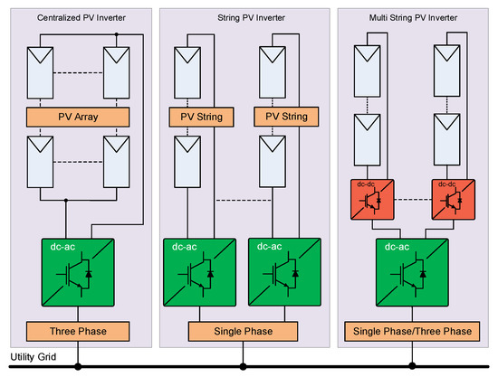
Figure 1.
Photovoltaic (PV) inverter configurations.
The latest researches in single-phase solar inverter topologies are focused on removing the transformer requirement, and providing alternative isolation methods for maintaining the security requirements [7,11,12,15]. Although the galvanic isolation was an obligation in terms of safety regulations for many years, the recent arrangements have led to the use of capacitive isolation which allows to design lighter inverters. The transformerless solar inverters have proved their efficiency and reliability with several applications in many residential and industrial areas. The advantages of transformerless inverter topologies have been analyzed in [15] where many industrial inverters are compared in terms of overall efficiency, volume, power density and size.
In this paper, a robust control algorithm has been proposed for dc/dc converters in a multi-string PV inverter that includes a dual boost converter integrating solar strings to a dc-ac converter on the dc interface. Dual boost converters that are operated and controlled by the proposed MPPT system regulate the dc-link voltage required for the unfolding inverter. The existing MPPT controllers in the literature are based on feedforward control of dc converters regarding measured current and voltage values. On the other hand, some MPPT methods operating with only feedback signals have been proposed. The main contribution of this paper is to propose a novel MPPT method that combines advantages of feedforward and feedback based control in a single algorithm. The proposed MPPT algorithm is applied and is tested on the dc/dc converters of a single-phase two-stage transformerless multi-string inverter. The simulation and experimental results confirm that the proposed MPPT control method not only ensures the tracking of reference voltage closely but also guarantees the rejecting of shading effects. It is also important to note that the unfolding inverter and its control stages are out of the scope of this work since this paper is mainly focused on the implementation of MPPT control and the dc interface of a multi-string inverter.
This paper is organized as follows. In Section 2, a brief description of typical and recent single-phase transformerless PV inverters is presented, while Section 3 provides a brief analysis of the most widely used and recent MPPT algorithms. In addition, the design and contributions of proposed topology compared with the existing PV inverters are explained in Section 3. The design methodology and control strategy of the dc/dc converter is presented in Section 4. In Section 5, the modeling and simulation analyses are shown, and experimental studies and results are given in Section 6. Finally, conclusions are presented in Section 7.
2. Single-Phase Transformerless PV Inverters
The most important outcomes of recent discussions on transformerless inverters are to increase the overall efficiency due to removal of the transformer, to improve efficient MPPT control, and to decrease the leakage current of this new isolation type. The increased integration of solar plants at the LV medium have promoted the research and improvements of single-phase transformerless PV inverters as a commercial technology. The extensive researches on single-phase solar inverters have focused on novel inverter topologies such as highly efficient and reliable concept (HERIC), T-type, H5 and H6 in addition to traditional H-bridge and neutral point clamp (NPC) configurations [16]. The literature survey has shown that solar inverters are configured either in single-stage or in two-stage structure owing to their dc-bus limits and grounding requirements. The single-stage topologies are commonly comprised of an inverting section which interfaces solar arrays and generates ac output while the two-stage topologies are improved with a dc/dc converter at the first stage and inverter section in the second stage. Figure 2 represents the most widely known topologies of novel solar inverters as single or two-stage configurations [9,11,15,17,18,19,20,21]. Figure 2a shows a transformerless solar inverter in single-stage configuration with a dc link capacitor acting as the input source of the MPPT controller [19]. The inverting stage of this topology is comprised by an asymmetrical half-bridge network. On the other hand, an NPC topology configured in H-bridge structure is seen in Figure 2b in which the device is titled as H-NPC topology due to configuration, and it is operated in single-stage architecture. Another common mode of transformerless inverter topology has been given in Figure 2c where the leakage currents are eliminated [17,21]. The MPPT controller of this topology requires high input voltage which is supplied by a boost converter comprising the first stage of topology. Although the switching device numbers are lower than other inverters, this common-mode inverter requires increased number of passive devices compared to other configurations. A recent application of NPC in a two-stage PV inverter is shown in Figure 2d where a boost converter has comprised a dc/dc converter and the grounding has been provided by the middle point of the half-bridge NPC branch [11]. Although resonant converter topologies have been proposed in this configuration, the efficiency of the inverter has been limited and thus it is not accepted in industrial and commercial applications. The most efficient and commercially accepted two-stage HERIC and H5 topologies are presented in Figure 2e,f, respectively. Both of these topologies are widely researched due to increased efficiency and leading structure in managing the coupling of solar arrays with the utility grid. The H5 and H6 topologies are commonly derived from HERIC topology by integrating fifth and sixth switching devices on positive and negative input terminals of conventional H-bridge topology [18].
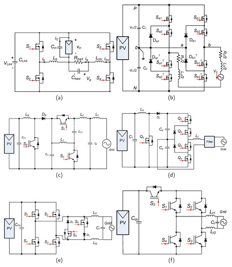
Figure 2.
Single phase solar inverter configurations, (a) single-stage structure [19], (b) single-stage H-NPC [20], (c) common-mode transformerless [17], (d) boost converter+NPC two-stage [11], (e) two-stage highly efficient and reliable concept (HERIC) inverter [18], (f) H5 inverter [18].
The proposed converter that is introduced in Section 4 is designed in a single-phase transformerless two-stage configuration. The dc/dc conversion stage has been comprised of boost converters to achieve a multi-string topology. On the other hand, the dc-ac conversion has been performed by single-phase H-bridge topology to decrease the passive components and switching losses while it increases the inverter efficiency. A brief description of MPPT methods that are state-of-the-art is presented in the following section. Thus, it will facilitate expressing our contribution to a controlling strategy by comparing existing literature.
3. Maximum Power Point Tracking (MPPT) Algorithms
The deviation of input voltage and current of a solar array is detected by using an MPPT algorithm in solar inverters. The MPPT algorithm is responsible for forcing the converter to use maximum available power. However, the stable and unstable conditions of solar array should be closely tracked and reacted timely. The efficiency of a solar power conversion system depends to the load variations as well as source deviations. The unstable and changing operation circumstances should be dealt by an MPPT algorithm for ensuring the reliable and efficient operation in a power converter. Many MPPT methods and approaches have been proposed in the current literature [12,22,23]. The hill-climbing, perturb-and-observe (P&O) and incremental conductance (InCon) MPPT methods have been used for many years due to their simple and low cost structure in implementation. In addition to research studies, lots of the commercial solar inverters also take advantage of hill-climbing and P&O MPPTs. The novel MPPT methods have been improved with a number of soft-computing methods such as artificial neural networks (ANN), particle swarm optimization (PSO), and genetic algorithms (GA). The soft-computing methods ensure more precise calculations, but they lack in simplicity and low-cost structure due to high-performance processor requirements [12,22]. The increased mathematical calculation requirement of soft-computing methods decreases the response time while the cost of the processor is increased due to performance conditions. The capacitor control, and MPPT algorithms are improved with feedback signal based control [16,22,24,25,26].
The MPPT algorithms are expected to deal with decreased efficiency of the solar plant by detecting the maximum power point. However, algorithms are not mostly able to detect the difference in local MPP (LMPP) and global MPP (GMPP) under partial shading circumstances. Therefore, traditional MPPT methods are not capable to efficiently operate in partial shading situations [25,26].
The proposed control algorithm in this study is based on the adoption of the conventional P&O algorithm and output voltage feedback. In other words, the configurations of feedforward and feedback type controllers are combined in terms of hardware, and a featured control algorithm has been implemented with low-cost requirements. The proposed MPPT method is improved by considering the output voltage of dc/dc converter that is drastically decreased under partial shading conditions. Furthermore, the proposed MPPT method integrates an improved P&O algorithm with a PI controller for voltage feedback.
4. Design and Control Strategy of The Converter
The presented converter is composed of a two-stage structure where boost dc/dc converters comprise the first stage while the second stage is a fundamental single-phase H-bridge inverter. The converters are shunt connected to enclose the point of common coupling (PCC) at dc-bus, as shown in Figure 3. The solar modules cause parasitic capacitance at their positive and negative terminals due to its grounded frame. In addition to this, the potential difference occurred during switching transitions of converter injects leakage current on dc and ac side along the solar inverter. The leakage current increases the electromagnetic interferences (EMI), harmonic rates, grid distortions and distorts the safety. One of the most common solutions is to connect a parasitic capacitance between positive and negative terminals of solar modules and ground in transformerless topologies. The value of capacitance is suggested to be around 50–220 nF/kW in a single-capacitor model [20,27,28]. Therefore, each positive and negative terminal of solar arrays are equipped with 1 F film capacitors, as shown in dashed lines in Figure 3.
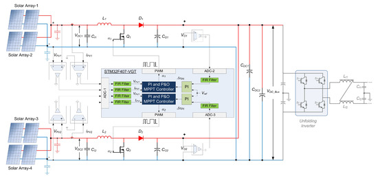
Figure 3.
Block diagram of proposed two-stage PV inverter and control system.
An STM32F407 microprocessor that is one from the 32-bit ARM family manages the control operations. Each boost converter includes a hall-effect current sensor to track PV currents while resistor networks perform the voltage sensing of capacitors at the input and output of the converter. The sensed values are supplied to analog-digital converter (ADC) ports of the microprocessor by the signal conditioning circuits that are composed of isolation amplifiers. In other words, each boost converter provides three measurement signals to the microprocessor that are PV current, input capacitor voltage, and output capacitor voltage. Although the signal conditioning circuits include passive low-pass filters, the acquired signals are filtered by a software-based finite impulse response (FIR) filter in the microprocessor. Once the inherited digital signals are filtered, input measurements are transferred to the P&O section, and output capacitor measurement is applied to the PI controller as illustrated in the block diagram. The control algorithm is dependent on three input signals obtained from a hall-effect sensor for current and resistor networks for voltages. Therefore, the additional circuit required for the control algorithm is achieved with a low-cost design. The design studies are presented in two sections, one is on data acquisition and signal conditioning networks, and the other one is on the control algorithm.
4.1. Design Criteria of Proposed Control Method
The control algorithm requires a data acquisition interface transmitting the measured signals to the microprocessor. The measurement points at the boost converter, as shown in Figure 4a, inherit the input parameters that are involved in the control algorithm, and the signal conditioning circuit is designed as presented in Figure 4b. The input capacitor is responsible for mitigating the switching ripples that cause fluctuations in inductor current and ensures achieving an average current flow along with the inductor. The input capacitor and inductor share the current provided by solar array that is shown as with respect to the Kirchoff’s current law as follows;
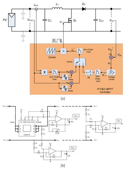
Figure 4.
Block diagram of proposed converter and control system, (a) boost converter with control system, (b) signal conditioning interface along converter and microprocessor.
The driving signal of semiconductors is the function of the error signal. Therefore, the reference current provided by the current controller in the MPPT block is as,
where is the instant current of solar array and is the deviation value of current from the reference of the controller. In this case, Equation (2) is revised by taking into consideration the current of parasitic capacitance ; the relation between input current, parasitic capacitance current , and reference current of controller is used to determine the feedforward error rate by using Equations (1) and (2),
which yields an error of zero when equals to and thus . The capacitor current will be zero in steady-state operation. The parasitic capacitance current will be zero in steady-state operation.
On the other hand, the second control stage of the MPPT controller is based on a PI compensator that is improved regarding to output voltage. The instant value of output voltage is achieved from the nodes of the output capacitor that is for the first boost converter. The transfer function of the output PI compensator is presented in Equation (6), the voltage error that is used as the reference for the compensation process is given in Equation (7), and the transfer function of the outer loop in Equation (8) as follows in s-domain.
where the transfer function given in Equation (8) is derived by considering the settling time and minimum switching time as given in Equations (9) and (10) for and parameters, respectively [24,29].
where the angular frequency is dependent on the time constant as . By selecting the damping ratio as , switching frequency at 25 kHz, and output capacitor as F, the natural frequency is calculated as rad/s. The and values are obtained as and by employing Equations (9) and (10), respectively. The outer compensator loop is arranged according to calculated values and additional tuning is performed to decrease the error band during experimental studies. The voltage reference of solar array is tracked in the PI P&O MPPT controller, and the switch is triggered to select the P&O algorithm or PI compensator regarding the MPP operation.
4.2. Design Criteria of MPPT Controller
Figure 5 shows the flowchart of the proposed PI P&O MPPT algorithm where the main program consists of two subroutines as PI and P&O functions. The initial step sets counters and registers instant power, instant voltage, instant current, and MPPT power to zero in Step 1. In the next step, the counter is increased by one and then MPPT calculations get started in Step 3. The voltage and current of PV, and the output voltage with the parameter are acquired, and PV power is calculated in Step 4. After storing the values, the algorithm compares the actual voltage and current with previously stored values for detecting power fluctuations. The measured PV power is compared with previous global MPP, and change in GMPP is detected in Step 5. The measured output voltage is compared with a reference boundary in Step 6 where the program jumps to the P&O function if the achieved voltage is not higher or lower than 90% or 110% of the desired output voltage. This operation is accomplished by the multiport switch seen in the orange block of Figure 4a. The switch is driven by the middle port connection which triggers the main program for calling PI or P&O subroutines. Once the achieved output voltage gets out of the boundary band, then the program calls the PI control subroutine starting from Step 7.
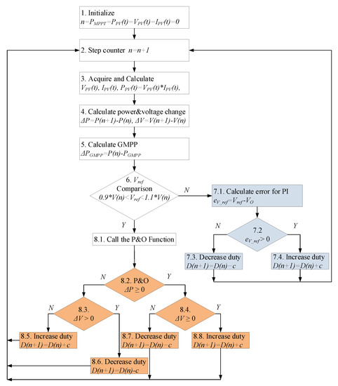
Figure 5.
Flowchart of the proposed PI perturb-and-observe (P&O) maximum power point tracking (MPPT) algorithm.
Once the PI compensation subroutine is called, the error voltage that implies the difference between reference and instant voltages is calculated in Step . In the case in which the error is positive according to the calculation in Step , it is detected that the output voltage is lower than the reference. Therefore, the duty cycle is increased in Step to increase the output voltage. When the output voltage of the converter is higher than the reference, the comparison in Step results negative and the duty cycle is decreased as denoted in Step . The reference voltage tracking operation is handled when the desired output voltage gets out of the boundary. Otherwise, the algorithm sustains the operation in the lower section of Figure 5 where the P&O MPPT is operated. The conventional P&O maintains operation at GMPP point until partial shading occurs at any time. The GMPP and MPP points were detected until Step , and the algorithm uses stored data to operate Step . When a partial shading occurs, the value in Step 4 changes and the main program operates the P&O function again to track the most recent MPP. The changes on are checked in Step and the comparison results define the operation to select at Step or Step . The required change on duty cycle is performed according to comparisons and the algorithm detects the recent GMPP to track starting from Step 2. There are several MPPT algorithms that have been proposed to perform similar operations with much more complex calculations and increased comparisons [29,30,31,32,33]. However, it is important to note that the proposed PI P&O flowchart provides refined algorithms and performs rapid comparisons when compared to others.
5. Modeling Studies
Several Matlab/Simulink modeling studies have been performed in order to evaluate the performance of the proposed PI P&O MPPT algorithm and to compare it with widely used algorithms. Therefore, a PV energy conversion system has been designed considering the block diagram given in Figure 3. Each dc/dc converter is supplied by parallel-connected solar arrays that are composed of four series-connected PV modules at each array. Thus, eight PV modules comprise a PV string connected to a dc/dc converter in Figure 3. The PV modules are modeled referring to a commercial one with V maximum power voltage and A maximum power current [34]. Two dc/dc converters operating in boost mode have been designed to interface the modeled PV plant. The design criteria of converters have been carried out regarding the schematic diagram presented in Figure 4a that the input and output capacitors are set as F and F while the inductor is mH. The switching frequency, steady-state current ripple, and voltage ripple values have been calculated by using the following equations where the instant duty cycle and switching frequency are obtained with Equations (11) and (12), respectively [29];
The denotes PV voltage as a supply of boost converter, while is output capacitor voltage, and is capacitor voltage ripple. The PV voltage is assumed as V due to solar array, V and V that yields . The switching frequency oscillates around nominal duty cycle and nominal switching frequency is calculated considering Equation (12) where the inductor current ripple is limited to A. Under these assumptions, kHz is achieved. On the other hand, the nominal values of the duty cycle and switching frequency at steady-state operation have been calculated by using Equations (13) and (14), respectively.
that yield and kHz. In order to put into evidence, the MPP tracking performance of the proposed method has been compared with widely used P&O and InCon MPPT methods. The modeled power converter system has been designed with the aforementioned values for passive devices and each of the MPPT algorithms has been tested by using identical Matlab/Simulink models. The irradiations and applied to each solar array have been arbitrarily varied to analyze partial shading conditions. The irradiations and variations are presented in Table 1. Figure 6 illustrates the simulation results of modeled MPPT controllers where the converter parameters and irradiation values have been applied as aforementioned. The array powers, converter and dc bus voltages, and duty cycles corresponding to presented and values have been measured for InCon (Figure 6a), P&O (Figure 6b) and proposed PI P&O MPPT (Figure 6c) algorithms. The first axis of each figure shows the supplied power of first and second array, and , respectively. The output voltages of converters and dc bus have been indicated with , , and titles in the second axis. The duty cycle ratios and variations have been illustrated in the third axis as and . The output power of solar arrays has been rapidly forced by irradiation when the converters are driven by InCon and P&O MPPT methods. It is exhibited that the power losses of the InCon controlled converter are higher than the P&O controlled converter. Therefore, the output voltage levels of and that are expected to be equal deviate due to variation of duty cycle ratios generated by the InCon and P&O MPPT controller. On the other hand, the output voltage levels of the P&O algorithm are more robust against irradiation changes while its oscillations are much more visible.

Table 1.
Irradiation changes and intervals.
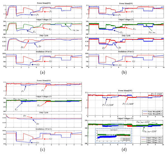
Figure 6.
Simulation results of modeled power converter and MPPT methods, (a) Incremental Conductance MPPT, (b) P&O MPPT, (c) Proposed PI P&O MPPT, (d) detailed and measurements for proposed method.
The presented figures show that the highest voltage of any converter supplies the output voltage where voltage oscillation reaches up to 80 V in the second interval covering seconds of simulation. The proposed MPPT controller satisfactorily tracks the irradiation changes and shifts the operation mode between the P&O and PI controller in the case of exceeding the predefined hysteresis band. This operation mode control is shown in the presented simulation results of Figure 6c that the output voltage of the dc bus is limited around the 5 V hysteresis band. The detailed view of output voltage fluctuations and power rates has been presented in Figure 6d. The output power of solar arrays is measured around and kW at various operation intervals where the rated total power of solar arrays is kW. Once the operation conditions and prototype optimizations have been carried out in simulation studies, the proposed MPPT method has been experimentally investigated. The test rig has been installed referring to simulation parameters and converters have been configured with calculated values.
6. Experimental Results
The MPPT algorithm proposed in this study has been experimentally tested and the success of the proposed algorithm has been compared with regular PI, InCon MPPT, and P&O MPPT algorithms. To verify the validity of the proposed algorithm, several partial shading conditions and varying irradiations have been applied by using a solar array simulator (Chroma 62050H-600S SAS) and programmable dc power supply as the second array input. The dual dc/dc converter has been implemented with the FBA75BA50 dual MOSFET module at 5 kW rated power. The operation conditions and device parameters used in the dc/dc converter test rig have been shown in Table 2. The current measurements have been realized by using hall-effect current transducers (CASR25-NP) that provide strict immunity while the voltage measurements have been performed by resistor networks with low cost. The fast recovery diodes (FREDs) used in the dc/dc converters are DSEI 60–10A diodes with 35 ns reverse recovery time . The accuracy and reliability of implemented measurement sections including hall-effect transducers and resistor networks have been tested in a wide operation range, and they have been integrated to dc converters after verifications. The implemented current and voltage measurement sections provide 98.33% accuracy for current and 99.85% for voltage measurement [1]. The achieved high accurate signals have been applied to ADC ports of the microprocessor where an FIR filter to ensure pure measurement signals have been detected to track if MPP initially filters the measurement signals. The sampling time of a microprocessor that has 168 MHz core speed has been set to 1 s and sampling times of PI and P&O algorithms has been set to 10 ms. The dual converter structure has been loaded with R-L loads in order to carry out several power rates. The implemented test rig has been shown in Figure 7 where the SAS interface of solar array configuration and shading analysis screen is depicted in Figure 7a, Chroma 62050H-600S SAS device in Figure 7b, dual boost converter setup in Figure 7c and measurement setup in Figure 7d. The partial shading analyses and solar array test have been performed by configuring SAS as predefined conditions as presented in simulation studies.
Table 2.
Components and values of dual boost converter.
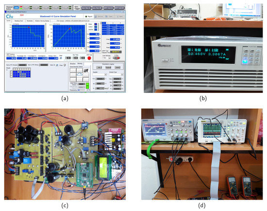
Figure 7.
Hardware and setup used in experimental studies, (a) solar array simulator (SAS) interface for partial shading configuration, (b) Chroma 62050H-600S SAS, (c) dual boost converter, (d) measurement system.
The experimental study results have been shown in Figure 8 and Figure 9 where each scope screen depicts 375 s of measurements (time/div = 25 s in Figure 8b, time/div = 50 s in Figure 8a,c). The second channel of scope (, 50 V/div) presents the first solar array input, third channel of scope (, 50 V/div) presents the third solar array input, and fourth channel (, 100 V/div) denotes the dc bus voltage of the converter. Figure 8 shows experimental results of the dc converter that is controlled by the PI controller, InCon MPPT, and P&O MPPT, respectively, in Figure 8a–c.
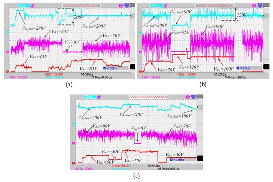
Figure 8.
Experimental results of MISO converter with different control methods, (a) PI, (b) InCon MPPT, (c) P&O MPPT.
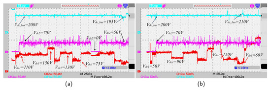
Figure 9.
Experimental results for PI P&O MPPT controlled converter under rapidly changing irradiations and partial shading.
The dc input voltages have been applied as a dual solar array as seen in Figure 8a. Although the PI controller provides stable operation during a single supply, it was not capable of tracking the desired reference voltage when both of the solar arrays were operated simultaneously or at different times. The overshoots or dips of output voltage have been extended up to 40% of the reference, as depicted in Figure 8a. On the other hand, the settling time takes around to stabilize the desired output when one of the sources is stopped to provide supply . The step time causes fluctuations on dc supply while InCon algorithm searches and tracks the MPP as seen in Figure 8b. The reference error is measured around 10% to 20% according to single or dual supply conditions. On the other hand, the output voltage oscillations reach up to during InCon MPPT control. Another comparison of the proposed algorithm has been carried out with regular P&O MPPT where Figure 8c shows the experimental results. In the case in which both inputs are supplied, the oscillations on the second input have been decreased as seen in Figure 8c, where the output voltage fluctuations sustain and the obtained output cannot track the desired reference voltage satisfactorily. Although the response time of P&O MPPT is lower than the InCon algorithm, it takes around to track the input voltage. Moreover, the reference error of the P&O algorithm has been measured as 5% referring to experimental results seen in Figure 8c.
The performance of the proposed MPPT algorithm has been tested and the experimental results have been given in Figure 9a,b under various operation conditions. In the first step shown in Figure 9a, a single supply has been applied for a short time and then the second supply has been integrated into the system. While a significant spike on output voltage has been observed in the previous three control methods, the proposed MPPT algorithm compensates for the connection and disconnections of any solar array at any time. The disconnection of the second solar array has been investigated at the 270th second where the second supply is set to . The first solar array has been configured to operate under partial shading conditions while the second source has been connected and disconnected to the system at stable irradiation. The proposed MPPT algorithm has provided successful tracking performance regarding reference value under highly and rapidly changing supply voltages. The reference error of the proposed method has been detected lower than 1%. In the next analysis shown in Figure 9b, the sources have been configured in order to operate under variously shading conditions. The first solar array has provided rapidly changing irradiations while the second one has provided relatively lower changes. The voltage level of the first source has been changed between and , and sudden increment and decrements have been applied to the dc converter.
The experimental test results clearly verified that the proposed MPPT control algorithm successfully tracks the desired output reference. Even under the worst operation conditions, the error rate on tracking the reference is below 5%, and the algorithm compensates this error lower than 2 s. Eventually, it is also confirmed by experimental studies in addition to simulation studies that the proposed MPPT algorithm is more robust against rapidly or slightly changing irradiations and more successful on tracking the reference values.
7. Conclusions
A two-stage MPPT algorithm is proposed for solar inverters in this study. The main contribution of the proposed method is to track voltage and current perturbation at the input and govern the output voltage at the dc bus. The enhanced MPPT algorithm, namely PI P&O MPPT, detects the oscillations that occurred on solar array power during partial shading and reacts to maintain providing stable dc voltage at the point of common coupling of dual dc/dc converters. Initially, the mathematical and simulation modeling of the proposed MPPT algorithm has been realized. After the modifications and implementations of the proposed MPPT method have been verified by simulation studies, the experimental results are achieved by using an implemented test rig of a dual dc/dc boost converter in which each of converters has been controlled with dedicated MPPT controllers. The STM32F407 microprocessor has been utilized to manage control operations and MPPT algorithms of converters. The proposed MPPT algorithm has been compared with conventional P&O and InCon methods. As the simulation and experimental results verify, the PI P&O algorithm decreases oscillations and fluctuations on solar array voltages, rejects the sudden or slight partial shading effects on input voltages, provides more resilient dc bus voltage with very low reference error, and rapidly reacts to source variations with the faster response time. It is also confirmed by experimental results that the deviation between the reference voltage and actual output voltage is lower than 5% at the worst operation conditions, and it provides the fastest tracking speed among other methods compared.
Author Contributions
All authors are involved equally in developing the full research manuscript for its final presentation. All authors have read and agreed to the published version of the manuscript.
Funding
This research was funded by TUBITAK under grant number 7141079. This work was supported by VILLUM FONDEN under the VILLUM Investigator Grant (no. 25920): Center for Research on Microgrids (CROM); www.crom.et.aau.dk.
Acknowledgments
Authors acknowledge to TUBITAK and VILLUM FONDEN for the funding support.
Conflicts of Interest
The authors declare no conflict of interest.
Abbreviations
The following abbreviations are used in this manuscript:
| dc link capacitor | |
| input capacitor | |
| nominal switching frequency | |
| parasitic capacitance current | |
| deviation value of current | |
| reference current | |
| inductor current | |
| instant current of solar array | |
| settling time | |
| minimum switching time | |
| damping ratio | |
| natural frequency | |
| Global MPP | |
| Highly Efficient and Reliable Concept | |
| Incremental Conductance | |
| Local MPP | |
| Maximum power point tracking | |
| Neutral Point Clamp | |
| Perturb-and-observe |
References
- Kabalci, E.; Kabalci, Y. A wireless metering and monitoring system for solar string inverters. Int. J. Electr. Power Energy Syst. 2018, 96, 282–295. [Google Scholar] [CrossRef]
- Kabalci, Y.; Kabalci, E. Modeling and analysis of a smart grid monitoring system for renewable energy sources. Solar Energy 2017, 153, 262–275. [Google Scholar] [CrossRef]
- Wu, W.; Ji, J.; Blaabjerg, F. Aalborg Inverter—A New Type of “Buck in Buck, Boost in Boost” Grid-Tied Inverter. IEEE Trans. Power Electron. 2015, 30, 4784–4793. [Google Scholar] [CrossRef]
- Schweizer, M.; Kolar, J.W. Design and Implementation of a Highly Efficient Three-Level T-Type Converter for Low-Voltage Applications. IEEE Trans. Power Electron. 2013, 28, 899–907. [Google Scholar] [CrossRef]
- Wang, C.; Yang, L.; Wang, Y.; Meng, Z.; Li, W.; Han, F. Circuit Configuration and Control of a Grid-Tie Small-Scale Wind Generation System for Expanded Wind Speed Range. IEEE Trans. Power Electron. 2017, 32, 5227–5247. [Google Scholar] [CrossRef]
- Gnanasambandam, K.; Edpuganti, A.; Rathore, A.K.; Srinivasan, D. Modified Synchronous Pulsewidth Modulation of Current-Fed Five-Level Inverter for Solar Integration. IEEE Trans. Power Electron. 2017, 32, 3370–3381. [Google Scholar] [CrossRef]
- Dutta, S.; Debnath, D.; Chatterjee, K. A Grid-Connected Single-Phase Transformerless Inverter Controlling Two Solar PV Arrays Operating Under Different Atmospheric Conditions. IEEE Trans. Ind. Electron. 2018, 65, 374–385. [Google Scholar] [CrossRef]
- Fuentes, C.D.; Rojas, C.A.; Renaudineau, H.; Kouro, S.; Perez, M.A.; Meynard, T. Experimental Validation of a Single DC Bus Cascaded H-Bridge Multilevel Inverter for Multistring Photovoltaic Systems. IEEE Trans. Ind. Electron. 2017, 64, 930–934. [Google Scholar] [CrossRef]
- Sasidharan, N.; Singh, J.G. A Novel Single-Stage Single-Phase Reconfigurable Inverter Topology for a Solar Powered Hybrid AC/DC Home. IEEE Trans. Ind. Electron. 2017, 64, 2820–2828. [Google Scholar] [CrossRef]
- Anthon, A.; Zhang, Z.; Andersen, M.A.E.; Holmes, D.G.; McGrath, B.; Teixeira, C.A. The Benefits of SiC mosfets in a T-Type Inverter for Grid-Tie Applications. IEEE Trans. Power Electron. 2017, 32, 2808–2821. [Google Scholar] [CrossRef]
- Meneses, D.; Blaabjerg, F.; García, Ó.; Cobos, J.A. Review and Comparison of Step-Up Transformerless Topologies for Photovoltaic AC-Module Application. IEEE Trans. Power Electron. 2013, 28, 2649–2663. [Google Scholar] [CrossRef]
- Romero-Cadaval, E.; Spagnuolo, G.; Franquelo, L.G.; Ramos-Paja, C.A.; Suntio, T.; Xiao, W.M. Grid-Connected Photovoltaic Generation Plants: Components and Operation. IEEE Ind. Electron. Mag. 2013, 7, 6–20. [Google Scholar] [CrossRef]
- El-Dein, M.Z.S.; Kazerani, M.; Salama, M.M.A. An Optimal Total Cross Tied Interconnection for Reducing Mismatch Losses in Photovoltaic Arrays. IEEE Trans. Sustain. Energy 2013, 4, 99–107. [Google Scholar] [CrossRef]
- El-Dein, M.Z.S.; Kazerani, M.; Salama, M.M.A. Optimal Photovoltaic Array Reconfiguration to Reduce Partial Shading Losses. IEEE Trans. Sustain. Energy 2013, 4, 145–153. [Google Scholar] [CrossRef]
- Kerekes, T.; Teodorescu, R.; Rodríguez, P.; Vázquez, G.; Aldabas, E. A New High-Efficiency Single-Phase Transformerless PV Inverter Topology. IEEE Trans. Ind. Electron. 2011, 58, 184–191. [Google Scholar] [CrossRef]
- Kabalcı, E. Review on novel single-phase grid-connected solar inverters: Circuits and control methods. Solar Energy 2020, 198, 247–274. [Google Scholar] [CrossRef]
- Azary, M.T.; Sabahi, M.; Babaei, E.; Meinagh, F.A.A. Modified Single-Phase Single-Stage Grid-Tied Flying Inductor Inverter With MPPT and Suppressed Leakage Current. IEEE Trans. Ind. Electron. 2018, 65, 221–231. [Google Scholar] [CrossRef]
- Chen, B.; Gu, B.; Zhang, L.; Zahid, Z.U.; Lai, J.; Liao, Z.; Hao, R. A High-Efficiency MOSFET Transformerless Inverter for Nonisolated Microinverter Applications. IEEE Trans. Power Electron. 2015, 30, 3610–3622. [Google Scholar] [CrossRef]
- Xia, Y.; Roy, J.; Ayyanar, R. A Capacitance-Minimized, Doubly Grounded Transformer less Photovoltaic Inverter With Inherent Active-Power Decoupling. IEEE Trans. Power Electron. 2017, 32, 5188–5201. [Google Scholar] [CrossRef]
- Rojas, C.A.; Aguirre, M.; Kouro, S.; Geyer, T.; Gutierrez, E. Leakage Current Mitigation in Photovoltaic String Inverter Using Predictive Control With Fixed Average Switching Frequency. IEEE Trans. Ind. Electron. 2017, 64, 9344–9354. [Google Scholar] [CrossRef]
- Vázquez, N.; Rosas, M.; Hernández, C.; Vázquez, E.; Perez-Pinal, F.J. A New Common-Mode Transformerless Photovoltaic Inverter. IEEE Trans. Ind. Electron. 2015, 62, 6381–6391. [Google Scholar] [CrossRef]
- Kabalci, E. Maximum power point tracking (MPPT) algorithms for photovoltaic systems. In Energy Harvesting and Energy Efficiency; Springer: Berlin, Germany, 2017; pp. 205–234. [Google Scholar]
- Moon, S.; Yoon, S.; Park, J. A New Low-Cost Centralized MPPT Controller System for Multiply Distributed Photovoltaic Power Conditioning Modules. IEEE Trans. Smart Grid 2015, 6, 2649–2658. [Google Scholar] [CrossRef]
- Montoya, D.G.; Ramos-Paja, C.A.; Giral, R. Improved Design of Sliding-Mode Controllers Based on the Requirements of MPPT Techniques. IEEE Trans. Power Electron. 2016, 31, 235–247. [Google Scholar] [CrossRef]
- Li, X.; Wen, H.; Hu, Y.; Jiang, L.; Xiao, W. Modified Beta Algorithm for GMPPT and Partial Shading Detection in Photovoltaic Systems. IEEE Trans. Power Electron. 2018, 33, 2172–2186. [Google Scholar] [CrossRef]
- Furtado, A.M.S.; Bradaschia, F.; Cavalcanti, M.C.; Limongi, L.R. A Reduced Voltage Range Global Maximum Power Point Tracking Algorithm for Photovoltaic Systems Under Partial Shading Conditions. IEEE Trans. Ind. Electron. 2018, 65, 3252–3262. [Google Scholar] [CrossRef]
- Chen, W.; Yang, X.; Zhang, W.; Song, X. Leakage current calculation for PV inverter system based on a parasitic capacitor model. IEEE Trans. Power Electron. 2016, 31, 8205–8217. [Google Scholar] [CrossRef]
- Kouro, S.; Leon, J.I.; Vinnikov, D.; Franquelo, L.G. Grid-connected photovoltaic systems: An overview of recent research and emerging PV converter technology. IEEE Ind. Electron. Mag. 2015, 9, 47–61. [Google Scholar] [CrossRef]
- Bianconi, E.; Calvente, J.; Giral, R.; Mamarelis, E.; Petrone, G.; Ramos-Paja, C.A.; Spagnuolo, G.; Vitelli, M. A Fast Current-Based MPPT Technique Employing Sliding Mode Control. IEEE Trans. Ind. Electron. 2013, 60, 1168–1178. [Google Scholar] [CrossRef]
- Brito, M.A.G.d.; Galotto, L.; Sampaio, L.P.; Melo, G.d.A.E.; Canesin, C.A. Evaluation of the Main MPPT Techniques for Photovoltaic Applications. IEEE Trans. Ind. Electron. 2013, 60, 1156–1167. [Google Scholar] [CrossRef]
- Manickam, C.; Raman, G.P.; Raman, G.R.; Ganesan, S.I.; Chilakapati, N. Efficient global maximum power point tracking technique for a partially shaded photovoltaic string. IET Power Electron. 2016, 9, 2637–2644. [Google Scholar] [CrossRef]
- Chen, K.; Tian, S.; Cheng, Y.; Bai, L. An Improved MPPT Controller for Photovoltaic System Under Partial Shading Condition. IEEE Trans. Sustain. Energy 2014, 5, 978–985. [Google Scholar] [CrossRef]
- Ahmed, J.; Salam, Z. An Accurate Method for MPPT to Detect the Partial Shading Occurrence in a PV System. IEEE Trans. Ind. Inform. 2017, 13, 2151–2161. [Google Scholar] [CrossRef]
- Technical Datasheet. SunPower 305 Solar Panel. Technical Report. 2007. Available online: https://www.pocosolar.com/wp-content/themes/twentyfifteen/pdfs/Sunpower%20Solar%20Panels/sunpower_305wht_spec_sheet.pdf (accessed on 13 July 2020).


© 2020 by the authors. Licensee MDPI, Basel, Switzerland. This article is an open access article distributed under the terms and conditions of the Creative Commons Attribution (CC BY) license (http://creativecommons.org/licenses/by/4.0/).