Article

Electromagnetic Vibration Analysis and Slot–Pole Structural Optimization for a Novel Integrated Permanent Magnet In-Wheel Motor

1
School of Transportation, Shandong University of Science and Technology, Qingdao 266590, China
2
College of Chemical and Biological Engineering, Shandong University of Science and Technology, Qingdao 266590, China
3
College of Energy and Power Engineering, Nanjing University of Aeronautics and Astronautics, Nanjing 210016, China
*
Author to whom correspondence should be addressed.
Energies 2020, 13(13), 3488; https://doi.org/10.3390/en13133488
Submission received: 19 March 2020 / Revised: 24 June 2020 / Accepted: 28 June 2020 / Published: 6 July 2020
(This article belongs to the Section E: Electric Vehicles)

Abstract

:
This paper presents a novel integrated permanent magnet (PM) in-wheel motor (IWM) driving system for electric vehicles (EVs), in order to overcome the disadvantages of electromagnetic vibration and cogging torque in the topology scheme, on the basis of maintaining high output torque. Firstly, the transient magnetic field of the integrated PM motor is analyzed using the improved analytical subdomain model and finite element (FE) model. The harmonic component of magnetic force density (MFD) is obtained with no-load condition. Furthermore, the vertical dynamic model for the dynamic vibration absorber is established to investigate the influence of the magnetic force harmonic on the vibration response of the stator and rotor. On this basis, the multi-objective optimization design of the pole–slot structure parameters is carried out by using the adaptive weighted particle swarm optimization (AWPSO) algorithm. Finally, the optimization results are compared and verified by FE analysis. The investigation shows that the unbalanced magnetic force and cogging torque is significantly reduced by the adjustment of the pole-arc coefficient, PM thickness, stator slot width and slot opening width.

1. Introduction

In recent years, as new-energy vehicles are being widely promoted, the relevant scientific research institutions have also carried out innovative investigations into the core parts of automobiles. The driving motor is one of the main technologies in the transformation of electric vehicles, which has also changed, from centralized wheel-side to in-wheel driving. Moreover, the permanent magnet (PM) motor has gradually become the preferred scheme of IWM, due to its high specific power, strong overload capacity, and low cost, with simple construction and maintenance. However, the presence of magnets, which is essential for torque production, provides the harmonic component of electromagnetic force, which will cause greater stator and rotor deformation, thus aggravating the electromagnetic vibration, so that the ride comfort and safety of the vehicles will be seriously affected [1]. Consequently, decreasing electromagnetic force harmonics, and simultaneously maintaining high output torque, has become a challenging issue in the novel IWM design.
The electromagnetic vibration of the PM motor is investigated using the theory of magnetism–solid coupling, as it is necessary to consider both the distribution of electromagnetic force and the structural modal of the motor [2]. The harmonic of magnetic force is one of the main causes of electromagnetic vibration; as such, its accurate calculation is the key to vibration analysis and optimization [3,4,5]. At present, there are generally two approaches to calculating the distribution of the magnetic field: approximate analytical and numerical calculation. The approximate analytical method is typically used to predict the distribution of the magnetic field via vector potential and permeability. Zhu et al. [6] utilized the accurate analytical subdomain model for predicting the open-circuit magnetic field in a PM motor, and accordingly the harmonic component of radial electromagnetic force was calculated. However, the influence of stator slotting tooth-tips on the magnetic field distribution was ignored. Thus, on the basis of the above model, the effect of the stator slotting structure on the magnetic field distribution is revealed in [7,8]. Krotsch et al. [9] described the diversity of spatial and specific frequency harmonic ordinal numbers of different slot and pole number combinations within the open circuit, and pointed out higher frequency harmonics significantly depend on the pole and tooth shape. On this basis, the influence of the stator tooth structure [10], pole-arc coefficient [11] and permeability of PM [12] on the radial magnetic force harmonic were discussed, and the validity and accuracy of the analysis results were verified by experimental tests. Nevertheless, in view of the structure and size differences in PM motors, the influence of different harmonic frequencies and amplitudes of magnetic force on vibration still need to be further explained in these motors. In terms of resonance frequency, Ko et al. [13] investigated the coupled magnetic–mechanic vibration combined with the structural characteristics in a permanent magnet brushless motor. In terms of harmonic amplitude, Jang et al. [14] discussed the vibration response of permanent magnet synchronous motor (PMSM) to the spatial and temporal harmonic components of radial electromagnetic magnetic force. Additionally, Zuo et al. [15] indicated the influences of spatial order, frequency and amplitude of radial magnetic force on the electromagnetic vibration of PMSM. Although the vibration problem under the action of the electromagnetic force harmonic component was discussed in many studies, only a few works on the integration form of outer-rotor topologies based on the existing analytical models. Thus, the coupled vibration level of the integrated PM motor for the electric wheel needs to be further explored.
Since the electromagnetic vibration was mainly affected by the radial magnetic harmonic, several researchers proposed to suppress the vibration by optimizing the stator and rotor structure. In the design process, Lee et al. [16] presented the response-surface methodology for optimizing the slot–pole combination, so as to eliminate the harmonic components caused by the non-ideal spatial distribution of radial flux density. However, this selection was generally limited by other performance requirements. When the control method and slot–pole combination are determined, some other work can also be done to reduce vibration. Sai et al. [17] suggested changing the slot–pole number in combination with tooth notching, in order to reduce the main electromagnetic exciting force. Hur et al. [18] introduced the harmonics elimination method by alternating the distribution of radial flux density, in order to achieve the optimal design for the chamfering and slotting dimensions of the rotor structure. Min et al. [19] applied the particle swarm optimization algorithm to achieve an optimal design for the parameters of PM thickness and tooth width. However, the structural vibrations of a motor due to the magnetic forces acting on the teeth of the stator were not considered. Lee et al. [20] utilized the FE optimization method to design the stator tooth thickness and tooth shoe size. Kim et al. [21] improved the amplitude and frequency of the magnetic force harmonic by optimizing the pole angle of the rotor, the length of the stator tooth, and the thickness of the tooth shoe. However, the effect of changing the stator structure on stator modes should also be carefully considered when it is adopted to reduce force harmonics. Lin et al. [22] optimized the slot opening width, magnet shape and magnet skewing in order to change the amplitude and phase of the electromagnetic force harmonic. Note here that the above methods might result in a clashing of the optimization objectives as a result of the optimization procedure. Considering the requirements of low electromagnetic vibration and low cogging torque for the IWM, the optimization of the motor is actually a multi-objective and multi-variable optimization process. In view of the advantages of the adaptive particle swarm optimization algorithm in solving the multi-objective functions, in this paper, an adaptive weighted particle swarm optimization method for motor structure parameter optimization is presented.
This paper reports on the optimal design of the proposed integrated IWM, based on electromagnetic vibration sources. Firstly, the magnetic flux densities are analyzed using the improved analytical subdomain model and the FE numerical method, and the magnetic forces are calculated using the Maxwell stress tensor method. Next, the influence of the radial magnetic force harmonic on the vibration characteristics of the stator and rotor is explained based on the IWM dynamics model. Furthermore, the multi-objective optimization design of pole–slot structure’s parameters is carried out using the AWPSO algorithm. Finally, the optimal combination of design variables is selected according to the objective functions, and the electromagnetic force distributions in the initial and optimal motors are compared by the FE method. Accordingly, the validity and correctness of the optimization design process is confirmed.

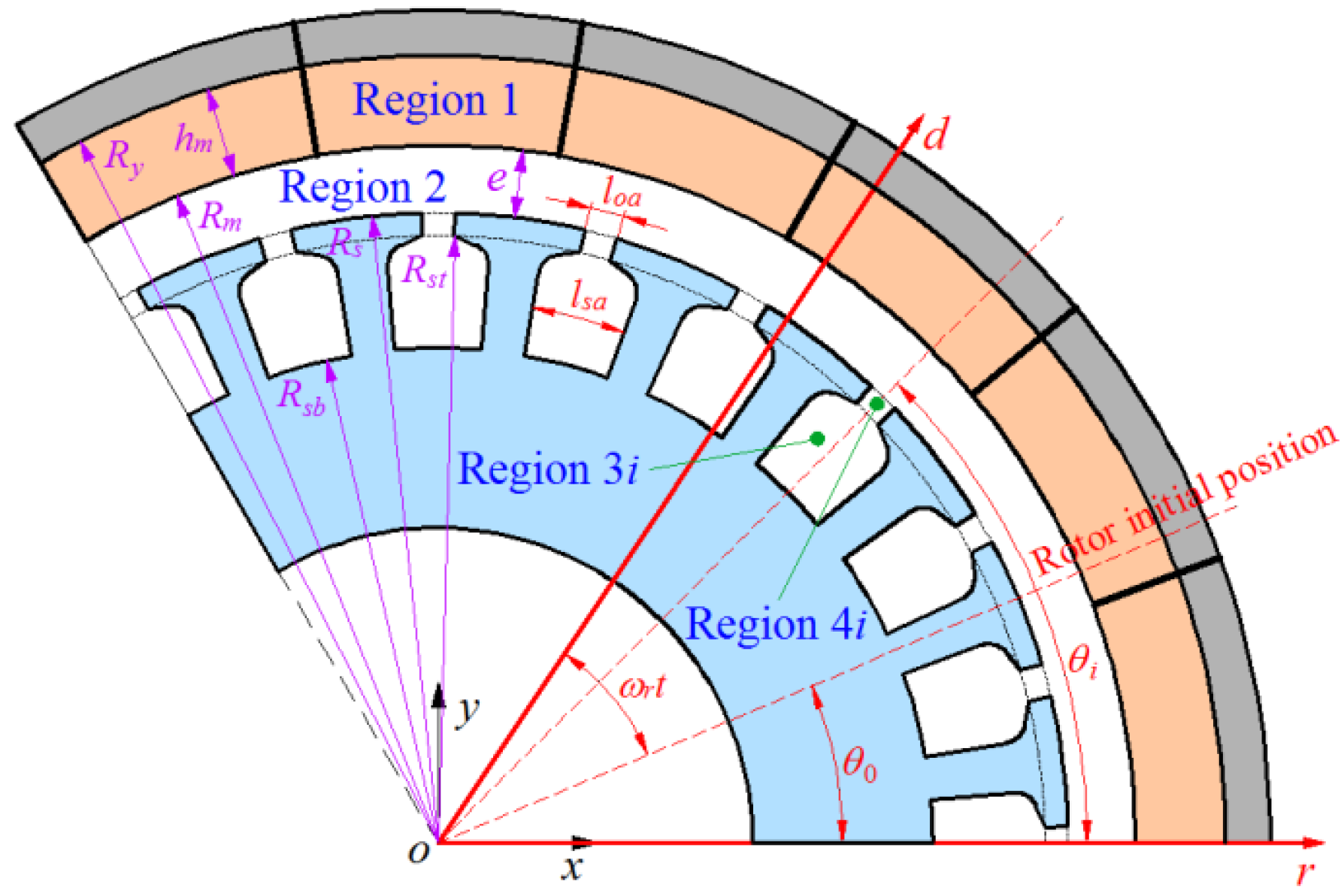
2. Structure of the Integrated PM-IWM

For the existing IWM driving system, the power is transmitted directly to the driven wheels, and the transmission shaft, differential and speed reducer are omitted. However, the unsprung mass is increased in this driven mode, which leads to critical vehicle dynamics issues. As for the outer-rotor type IWM topology, the motor stator is rigidly fixed on the knighthead, and the rotor is rigidly fixed to the rotating wheel hub. The relative displacements between the stator and the rotor will be generated when the IWM suffers from pavement load excitation. These relative displacements directly cause the motor magnet gap deformation. Additionally, there is some redundancy in the parallel design of the rotor housing and hub. To overcome the drawbacks mentioned above, a novel integrated PM-IWM driving system is brought forward in this paper, and its topology scheme is shown in Figure 1. It is mainly composed of IWM, a special hub, a suspending sleeve, a bearing, a brake disc assembly, and so on. Notably, the hub, rotor housing and brake disc are designed in an integrated way. The stator is flexibly connected to the wheel shaft by the suspending sleeve and annular rubber bushing, and the integrated rotor is supported on the wheel shaft by the bearing. The thermal insulation pad, rotor yoke and permanent magnet are bonded to the inner cavity of the hub one by one, and the permanent magnet is fixedly connected at the wheel rim with pegs. Moreover, the hard thermal insulation pad is added at the connection between the rim and brake disc, in order to reduce the heat transfer, and the S-type circulating waterway connected with the external cooling system is added inside the stator.
Compared with the existing outer-rotor IWM, the integrated IWM’s structural advantages lie in the following aspects. The unsprung mass is effectively reduced by the integrated design of the IWM rotor. The stator is elastically isolated from the wheel shaft by the suspending sleeve, which acts as a dynamic vibration absorber. Meanwhile, the relative dynamic deflection between stator and rotor can also be restricted by the suspending sleeve. In addition, the problem of the integrated IWM temperature’s increase is relieved by the design of the S-type circulating waterway. In view of the above, the dynamic characteristics of the integrated IWM driving system will be effectively improved.

3. Analysis of Magnetic Exciting Source

3.1. Analytical Model of Magnetic Field

To derive the analytical model of the proposed integrated PM motor, some assumptions are made in this paper to simplify the problem, as follows [6,7,8]: (1) simplified slot but with tooth-tips, as shown in Figure 2; (2) negligible end effect; (3) infinite permeability of iron materials; (4) nonconductive magnet material; and (5) linear demagnetization rate of magnet.

3.1.1. Vector Potential Distribution

The vector potential has only a z-axis component in the 2-D field, that is, the vector potential equation of each subdomain can be obtained as follows:
2 A z j r 2 + 1 r A z j r + 1 r 2 2 A z j θ 2 = { μ 0 r ( M θ M r θ ) , j = 1 0 , j = 2 , 3 , 4
where A z j is the vector magnetic potential, and the subscript j represents different subdomains, r and θ are the radial and circumferential positions, respectively, and μ 0 is the permeability of vacuum. M r and M θ are the radial and circumferential components of magnet magnetization, respectively, which can be expressed as:
{ M r = k = 1 , 3 , 5 , M r k cos k [ θ ( ω r t + θ 0 ) ] = k = 1 , 3 , 5 , ( M r c k cos k θ + M r s k sin k θ ) M θ = k = 1 , 3 , 5 , M θ k sin k [ θ ( ω r t + θ 0 ) ] = k = 1 , 3 , 5 , ( M θ c k cos k θ + M θ s k sin k θ )
with
{ M r c k = M r k cos ( k ω r t + k θ 0 ) M r s k = M r k sin ( k ω r t + k θ 0 ) M θ c k = M θ k sin ( k ω r t + k θ 0 ) M θ s k = M θ k cos ( k ω r t + k θ 0 )
For radial magnetization:
{ M r k = 4 p B r k π μ 0 sin k π σ p 2 p M θ k = 0       k / p = 1 , 3 , 5 ,
For parallel magnetization:
{ M r k = B r μ 0 σ p [ sin ( ( k + 1 ) σ p ( π / 2 p ) ) ( k + 1 ) σ p ( π / 2 p ) + sin ( ( k 1 ) σ p ( π / 2 p ) ) ( k 1 ) σ p ( π / 2 p ) ] M θ k = B r μ 0 σ p [ sin ( ( k + 1 ) σ p ( π / 2 p ) ) ( k + 1 ) σ p ( π / 2 p ) sin ( ( k 1 ) σ p ( π / 2 p ) ) ( k 1 ) σ p ( π / 2 p ) ] ,       k / p = 1 , 3 , 5 ,
where θ 0 is the rotor’s initial position, ω r is the rotor’s rotational speed, p is the number of pole pairs, B r is the remanence of the magnet and σ p is the pole–arc ratio.
The general expressions of the vector potential distribution for each subdomain in the polar coordinates are obtained by the separating variables method, which can be expressed by:
A z 1 = k { [ ( r R m ) k + ( R y R m ) k ( r R y ) k ] C 11 + μ 0 M θ c k k 2 1 [ r + k R y ( r R y ) k ] μ 0 M r s k k 2 1 [ k r + R y ( r R y ) k ] } cos ( k θ ) + k { [ ( r R m ) k + ( R y R m ) k ( r R y ) k ] C 13 + μ 0 M θ s k k 2 1 [ r + k R y ( r R y ) k ] + μ 0 M r c k k 2 1 [ k r + R y ( r R y ) k ] } sin ( k θ )
for Region 1, and
A z 2 = k [ C 21 ( r R m ) k + C 22 ( r R s ) k ] cos ( k θ ) + k [ C 23 ( r R m ) k + C 24 ( r R s ) k ] sin ( k θ )
for Region 2, and
A z 3 i = n C 34 i [ ( R s t R s b ) E n ( r R s b ) E n + ( r R s t ) E n ] cos [ E n ( θ + l s a 2 θ i ) ]
for the i-th slot, Region 3i, and
A z 4 i = m [ C 41 i ( r R s ) F m + C 42 i ( r R s t ) F m ] cos [ F m ( θ + l o a 2 θ i ) ]
for the i-th slot opening, Region 4i.
{ E n = n π / l s a F m = m π / l o a
where R m , R y and R s are the radius of the magnet, rotor yoke surfaces and stator bore, respectively, R s b and R s t are the radius of the slot bottom and top, respectively, l s a and l o a are the slot and slot opening width angle, respectively. θ i is the position of the i-th slot, C i 1 , C i 2 , C i 3 and C i 4 ( i = 1 , 2 ) are coefficients to be determined, and C 34 i , C 43 i and C 44 i are coefficients to be determined.

3.1.2. Interface Conditions and Harmonic Coefficient Solution

According to the continuity of radial and tangential flux density, the interface conditions between subdomains can be obtained. The radial and circumferential components of flux density can be obtained from the vector potential distribution by:
{ B r = 1 r A z θ B θ = A z r
(A). Interface between permanent magnet and air-gap ( r = R m )
The continuous conditions of the interface between PM and air-gap subdomain are as follows:
{ B 1 r | r = R m = B 2 r | r = R m H 1 θ | r = R m = H 2 θ | r = R m
with
{ H 1 θ = ( B 1 θ / μ 0 M θ ) / μ r H 2 θ = B 2 θ / μ 0
where H i θ is the magnetic field intensity, and μ r is the relative permeability of magnet.
(B). Interface between slot opening and air-gap ( r = R s )
According to the infinite permeability of the stator core material, the circumferential component flux density of the whole circumference [ 0 , 2 π ] along the interface between the slot opening and the air-gap, can be expressed by:
B s θ = { A z 4 i r , θ i l o a / 2 θ θ i + l o a / 2 0 , Other   Regions
According to vector potential and normal flux density continuation, the interface conditions are as follows:
{ A z 2 | r = R s = A z 4 i | r = R s B 2 θ | r = R s = A z 2 r | r = R s = B s θ | r = R s
(C). Interface between slot opening and slot ( r = R s t )
The circumferential component flux density distribution in the subdomain of the armature slot ( θ i l s a / 2 θ θ i + l s a / 2 ) can be expressed by
B t θ = { A z 4 i r , θ i l o a / 2 θ θ i + l o a / 2 0 , Other   Regions
and the interface conditions are as follows:
{ A z 3 i | r = R t = A z 4 i | r = R t B 3 i θ | r = R t = A z 3 i r | r = R t = B t θ | r = R t
Based on the continuous relationship between the magnetic fields, the above-obtained interface conditions between each subdomain are expanded by Fourier series, and paralleled into a matrix form, and the above harmonic coefficients can be obtained.

3.1.3. Flux Density of Air-Gap Subdomain

According to Equation (11), the magnetic flux density can be obtained. The radial and tangential flux densities in the air-gap can be expressed as
{ B 2 r = k k [ C 21 R m ( r R m ) k 1 + C 22 R s ( r R s ) k 1 ] sin ( k θ ) + k k [ C 23 R m ( r R m ) k 1 + C 24 R s ( r R s ) k 1 ] cos ( k θ ) B 2 θ = k k [ C 21 R m ( r R m ) k 1 C 22 R s ( r R s ) k 1 ] cos ( k θ ) k k [ C 23 R m ( r R m ) k 1 C 24 R s ( r R s ) k 1 ] sin ( k θ )
The obtained harmonic coefficients C 21 , C22, C 23 and C 24 are taken into Equation (18), and the radial and tangential air-gap flux densities with harmonic components can be obtained.

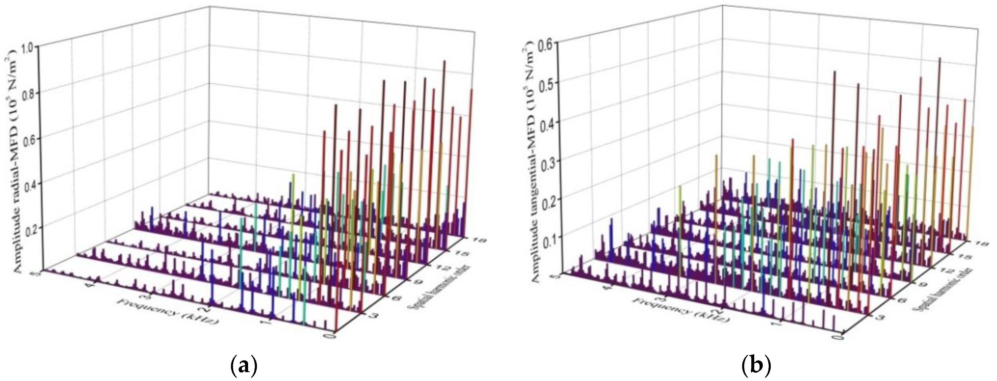
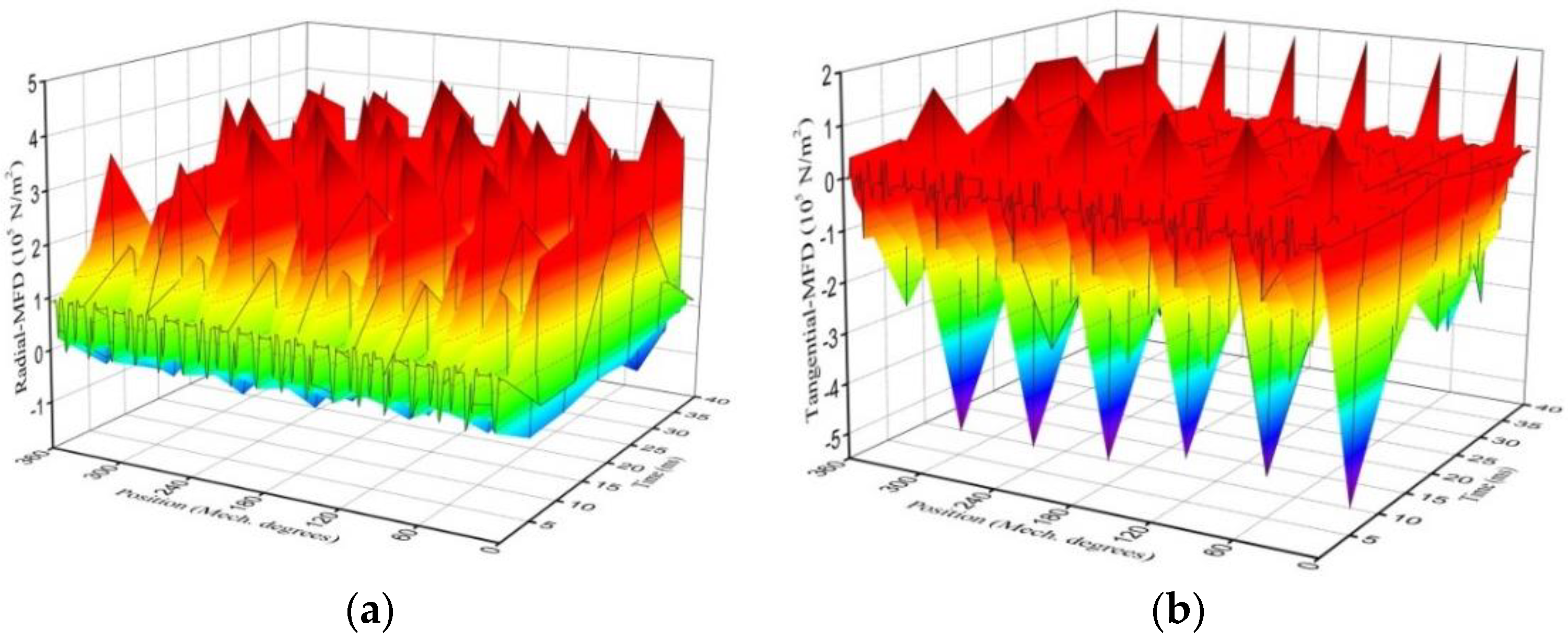
3.2. Electromagnetic Force Model

Since an accurate prediction of the magnetic flux density vector distribution is now available, it is expected that the electromagnetic forces can be calculated by directly using the Maxwell stress tensor method. The radial and tangential force densities in the air-gap can be expressed as:
{ f r = 1 2 μ 0 ( B 2 r 2 B 2 θ 2 ) f θ = 1 μ 0 B 2 r B 2 θ
Combined with the axial length of the motor, according to Equation (19), the cogging torque can be calculated from the air-gap flux density:
T c o g g = l a r 2 0 2 π f θ d θ
The unbalanced magnetic force can be calculated by:
{ F x = l a r 2 μ 0 0 2 π ( f r cos θ f θ sin θ ) d θ F y = l a r 2 μ 0 0 2 π ( f r sin θ + f θ cos θ ) d θ

3.3. Electromagnetic Finite Element Calculation and Analysis

The aforementioned analytical models are not only applicable in calculating the magnetic force distribution with any slot and pole combination, but also in investigating the influence of the pole-arc coefficient, PM thickness, stator slot width and slot opening width on the electromagnetic vibration. Nevertheless, the analysis of this part will be based on the prototype of the proposed integrated PM-IWM, wherein the magnetic field is studied by combining analytical calculation with the FE method. The main parameters of the PM motor are shown in Table 1.
The FE model of the integrated PM motor was established using the ANSYS Maxwell 2D, and the meshing in the FE was carefully adjusted before satisfactory results were achieved. Meanwhile, the stator winding is simulated by concentrated double-layer winding, the results of which are shown in Figure 3a. The magnetic field of the PM motor under the ideal current condition is calculated, and the distribution of the magnetic flux density after the stator teeth’s modulation is shown in Figure 3b. Furthermore, the interaction between the permanent magnet excitation field and the armature current excitation field produces the electromagnetic torque that drives the rotor to rotate. With the constant changing of magnetic flux, the rotor enters the rotating state, and the output power is shown in Figure 3c.
Figure 4a,b shows the comparison between the analytical calculation and FE prediction of the radial and tangential flux density waveforms at the center of the air-gap, r = ( R m + R s ) / 2 , without load. Notably, the slot in the analytical model accounting for tooth-tips has an equal width angle, but it increases when the position moves into the slot in the FE model, since the tooth body has a uniform width. However, the influence of such a difference is negligible, since the flux density drops significantly as the position moves deep into the slot. Obviously, the comparison shows a good agreement between the analytical and FE calculation results. Meanwhile, it also declares that the optimization of the PM motor’s structure parameters via the analytical model is reliable.
The comparison also shows that the improved analytical subdomain model has a high accuracy similar to the FE calculation for the MFD and slot opening. From Equation (21), it can be concluded that the radial and tangential magnetic forces have a certain influence on electromagnetic vibration. Therefore, the spatial distribution of the air-gap field in a rotation period is calculated using the FE method, and the radial and tangential magnetic force densities are obtained by Equation (19), as shown in Figure 5.
Then, to make the excitation source of vibration peaks clearer, the 2D-fast-fourier-transform (2D-FFT) is used to obtain the amplitude and frequency components of the specific spatial order of magnetic force, as shown in Figure 6. The sign of the frequency denotes the rotating direction of force wave, but the force harmonics with the 0th spatial order have no rotating direction. Notably, the greater amplitude of the radial and tangential magnetic force at the same location could result in a serious vibration response, and there are also excitation components close to the frequency of the stator modal, with the same spatial order.

4. Analysis of Vertical Electromagnetic Vibration

4.1. Vertical Dynamics Model

As depicted in Figure 1, the vehicle can be driven by controlling the rotation of the integrated IWM rotor, and the structure is supported on the wheel shaft by two bearings. As the hub bearing serves as a movable connecting unit and a load supporting unit, it is equivalent to a spring-damper system in the vertical direction. The stator is connected to the wheel shaft through the suspending sleeve and rubber bushing, in which the bushing does not transmit torque; only the radial stiffness and damping are considered in the Y and Z directions. We take no account of the mass of bearing and bushing, and the influence of the bearing clearance and the lubricant membrane are ignored. To reveal the influence of the magnetic force harmonic of the permanent magnet on the vibration response, the vertical dynamic model, considering the dynamic vibration absorber effect, is constructed based on the above assumptions, as shown in Figure 7, where only the vertical stiffness and damping of the bearings and bushings are considered, and all are assumed to be linear. In this model, the equivalent total spring and damper constant of the two bearings are k 21 , k 22 , c 21 and c 22 , and the bushing’s spring and damper constant are denoted by k 3 and c 3 . Here, m 1 is the total mass of the tire, rotor assembly and brake disc, m 2 is the total mass of the wheel shaft and brake clamp, and m 3 is the total mass of the stator mass and suspending sleeve.
According to Newton’s second law, the dynamic equations of the three-degrees-of-freedom model with the dynamic vibration absorber based can be formulated as:
{ m 1 y ¨ 1 + c 1 y ˙ 1 + c 21 ( y ˙ 1 y ˙ 2 ) + c 22 ( y ˙ 1 y ˙ 3 ) + k 1 y 1 + k 21 ( y 1 y 2 ) + k 22 ( y 1 y 3 ) = F e ( t ) m 2 y ¨ 2 + c 21 ( y ˙ 2 y ˙ 1 ) + c 3 ( y ˙ 2 y ˙ 3 ) + k 21 ( y 2 y 1 ) + k 3 ( y 2 y 3 ) = 0 m 3 y ¨ 3 + c 22 ( y ˙ 3 y ˙ 1 ) + c 3 ( y ˙ 3 y ˙ 2 ) + k 22 ( y 3 y 1 ) + k 3 ( y 3 y 2 ) = F e ( t )

4.2. Vibration Response under Magnetic Force Harmonics

For the integrated PM-IWM driving system in this paper, the main model parameters are listed in Table 2. Substituting the obtained unbalanced magnetic force and the parameters in Table 2 into Equation (22), the vibration response of the stator and rotor can be calculated, as shown in Figure 8.
Figure 8a shows the dynamic amplitude of the PM motor’s rotor and stator in a rotation period. The relative variation of the air-gap can be derived by e = y 3 y 1 . On the whole, the relative displacement of stator and rotor basically tends towards a certain range after 0.025 s. The maximum variation of the air-gap is 0.04 mm. The electromagnetic vibration can be aggravated by the resulting dynamic eccentricity to some extent. Meanwhile, the FFT is used to obtain the frequency components of the vibration response, as shown in Figure 8b. It can be seen that the vibration amplitude of the stator and rotor is larger in the low-frequency range, while the higher the frequency order, the smaller the response amplitude. As such, it also shows that the low-order magnetic force harmonics are the main source of vibration.

5. Optimization and Verification of Slot–Pole Structure Parameters

5.1. Multi-Objective Optimization Based on AWPSO Algorithm

It can be seen from the above analysis that the magnetic force harmonic is the main cause of electromagnetic vibration, which is mainly determined by the pole–slot structural parameters. Therefore, it is necessary to reduce the electromagnetic vibration response under the premise of protecting the motor’s performance. The pole-arc coefficient, PM thickness, stator slot width and slot opening width are selected as design variables in this paper, and the multi-objective optimization design of the pole–slot structure’s parameters is carried out by using the AWPSO algorithm. The preset range of design variables is shown in Table 3.
For the PM motor, the research focus is usually on high specific power, low vibration, low cogging torque, and so on. Since most of the requirements are in contradiction with each other, the optimization process is extremely difficult, with various variables that are strongly coupled. Hence, a systematic approach of adaptive weight is required to make a decision. In this section, the AWPSO algorithm is proposed and applied to the analytical model developed in Section 3.
The particle swarm optimization (PSO) is a stochastic optimization metaheuristic for nonlinear functions, which can be used to deal with continuous and discontinuous function decision-making optimization problems. Generally, the PSO algorithm is described mathematically as follows. Assuming that n particles form a population in an S-dimensional target search space, and each particle is flown with random and adaptable velocity to find the global optimal solution, the position and velocity of the i-th particle are expressed as X i = ( x i 1 , x i 2 , , x i s ) T and V i = ( v i 1 , v i 2 , , v i s ) T . In each iteration process, particles are manipulated according to Equations (22) and (23), where each particle tries to adjust its velocity to reach the optimal position. The best positions that have been stored in its memory are referred to as the individual best value p b e s t ( i ) = ( p i 1 , p i 2 , , p i s ) T , and the best previous position obtained by any particle in its neighborhood is called the global optimal value g b e s t ( i ) = ( g i 1 , g i 2 , , g i s ) T . Thus, particles communicate with each other, and distribute information among each other during their search; namely, the velocity and position of the k + 1 iteration of the i-th particle can be described as:
V i k + 1 = η V i k + c 1 r 1 ( p b e s t k X i k ) + c 2 r 2 ( g b e s t k X i k )
X i k + 1 = X i k + V i k + 1
where η is an inertia weight, η [ 0.4 ,   1.0 ] , c 1 and c 2 are the coefficients studied (the values used in the paper are c 1 = 1 . 5 and c 2 = 2 ), and r 1 and r 2 are uniform distribution numbers in the range [ 0 ,   1 ] .
In order to balance the search ability of the PSO algorithm in global and local ranges, and to ensure that an oscillating phenomenon is avoided in the global and local optimization solutions, the nonlinear dynamic inertia weight strategy is used to adjust the search range of the optimal solution. The expression is as follows:
{ η = η min + ( N k ) N × ( η max η min ) max { Δ x i k } Δ x i k Δ x i k = i = 1 s ( x i k g i k ) 2
in which η min and η max represent the maximum and minimum values of inertia weight (the values used in this paper are η min = 0.4 and η max = 0.9 ), Δ x i k is the distance between the i-th particle and the extreme position of the population at the k iteration, and N is the total number of iterations.
In this paper, taking the specific power, the vertical unbalanced magnetic force and the cogging torque as the optimization target, and the upper and lower values of the design variables as the constraint condition, the optimization model can be described as:
{ Minimize : W fitness = f ( X 1 , X 2 , X 3 , X 4 ) s . t . { X = [ X 1 , X 2 , X 3 , X 4 ] = [ σ p , h m , l s a , l o a ] X i min X i X i max , i = 1 , 2 , 3 , 4
in which W fitness is the adaptive target function, X i is the design variable, and X i min and X i max are the upper and lower values of design variables, respectively.
In the process of optimization, to make the design variables more cooperative with the optimal solution, the penalty function method will be used to deal with the constraint conditions. By constructing the penalty term, the non-linear programming problem that arises with constraints is transformed into an unconstrained optimization problem fit for solving. The points that do not satisfy the optimization procedure will be punished, so that the unconstrained points are forced to approach a feasible region and to converge on the minimum point. The augmented objective function can be constructed as:
W fitness = f ( X 1 , X 2 , X 3 , X 4 ) + δ { exp [ i = 1 s ( | min ( 0 , ( X i max X i ) ) + min ( 0 , ( X i X i min ) ) | ) ] 1 }
where δ is a larger constant.
The penalty value is 0 when the iteration value is within the preset constraint range, whereas the penalty function increases exponentially if the iteration value exceeds the constraint range. The farther away from the constraint boundary, the faster the penalty function value increases, and the optimization results will vary with the level of weighting factors for each performance index. The final iterative optimal values are shown in Figure 9.
It can be seen that the fluctuation of design variables σp, hm, lsa and loa meets the requirements, which are within the preset range. In the optimization, it is found that the optimization objective presents the cosine shape with a change of the single variable hm, and presents a hump shape with changes of variables σp, lsa and loa. Then, the design variables reach the best match after the adaptive weight iteration.

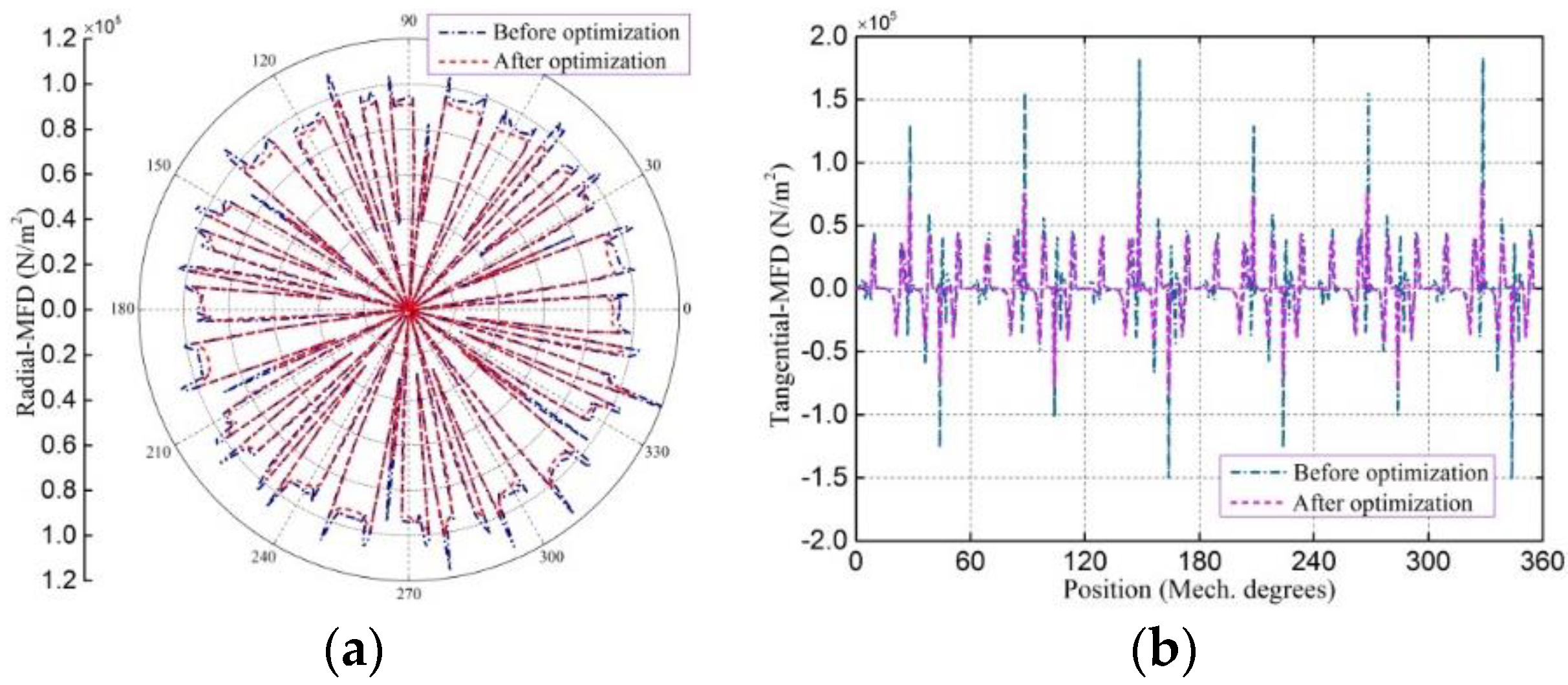
5.2. Verification and Discussions

To verify the validity of the proposed optimization method, the electromagnetic performances of the integrated PM-IWM at the initial and optimal design are compared in detail by the FE method. For the output power, the average value before and after optimization increased from 19.8 kw to 20.9 kw, with an increase of 5.55%. On the whole, the reduction of the unbalanced magnetic force and the cogging torque can be achieved simultaneously to some extent, under the basic improvement of output torque.
Figure 10 shows the radial and the tangential MFD analysis results of the initial and optimization models. As shown in the comparison of the analysis results, the amplitude of MFD decreased to some extent, and the MFD with the optimal dimensions is more symmetrical, which reduces the generation of unbalanced electromagnetic force. The maximum peak value of radial MFD is decreased by 14.79%, compared with that before optimization, and the maximum peak value of tangential MFD is decreased by 52.76%, compared with that before optimization. For better clarification, Figure 11 shows the corresponding amplitude–frequency analysis of the MFD. It can be found that the other multiple frequencies of MFD are not increased after optimization, and the amplitudes of the low order frequencies are greatly reduced. In addition, the 0 Hz frequency is a constant component, which will not produce vibration, and its change has little effect on the vibration. As such, the validity of the proposed optimization method is verified.
Figure 12a,b shows the comparison results of the vertical unbalanced magnetic force and cogging torque. As expected, the adjustment of the pole-arc coefficient, PM thickness, stator slot width and slot opening width has an effect on the distribution of the electromagnetic force. After optimization, the harmonic amplitude of magnetic force in the Y direction is decreased, and the waveforms become more symmetrical; as such, the unbalanced magnetic force is decreased by 61.22% of the initial value with the open-circuit. Meanwhile, the output curve of the cogging torque becomes smoother after optimization, and the maximum peak value is decreased by 31.57% of the initial value. It can be seen from the waveform that the optimized pole–slot structure’s parameters can effectively improve the air-gap electromagnetic force distribution, and reduce its harmonic component. Accordingly, the vibration and the torque ripple of the integrated PM motor are also effectively suppressed. According to the above analyses, a better optimization of the total vibration can be achieved by the above methods.

6. Conclusions

This paper proposes an integrated IWM direct driving system for potential applications in EVs, whereby high torque density and lower vertical vibration negative effects can be obtained. To overcome the disadvantages of high electromagnetic vibration and cogging torque in the proposed integrated IWM, and simultaneously maintain high output torque, the multi-objective optimization method is proposed to improve performance by adjusting the slot–pole structure’s parameters. Firstly, the no-load magnetic field distribution in the integrated PM motor is predicted using the improved analytical subdomain model. Combined with the Maxwell stress tensor method, the radial and tangential magnetic force density is calculated, and the validity of the analytical model is validated by the FE analysis. On this foundation, by applying FFT analysis to these excitation sources, the corresponding amplitude and frequencies that affect the vibration of the integrated PM motor have been investigated, and it is shown that the harmonic component of radial magnetic force is an important source of vibration. Furthermore, the vertical dynamic model of the integrated IWM driving system is established to investigate the vibration response of the stator and rotor, and the influence of the magnetic force harmonic on the vibration amplitude and frequencies of the stator and rotor is explained. Finally, based on the proposed AWPSO algorithm, the optimized design of the pole–slot structure’s parameters is carried out to reduce the unbalanced magnetic force and cogging torque. The optimization results are compared and verified by FE analysis. This research shows that the vibration response is significantly reduced by the adjustment of the pole-arc coefficient, PM thickness, stator slot width and slot opening width. Hence, the methodology can be applied in electromagnetic designs and structural designs, in order to reduce structural vibrations caused by magnetic force.

Author Contributions

Q.W. carried out the electromagnetic field model and optimization of the PM motor structural parameters, and wrote the original draft preparation. P.Z. investigated the analytical and finite element results. X.D. and F.L. helped with simulations and analysis. X.L. helped with the language checking. All authors carried out the data analysis, discussed the results and contributed to writing the paper. All authors have read and agreed to the published version of the manuscript.

Acknowledgments

This research was supported by the Scientific Research Foundation of Shandong University of Science and Technology for Recruited Talents (Grant No. 2017RCJJ053) and the National Nature Science Foundation of China (Grant No. 21506118).

Conflicts of Interest

The authors declare no conflict of interest.

References

  1. Deng, W.Z.; Zuo, S.G. Electromagnetic Vibration and Noise of the Permanent Magnet Synchronous Motors for Electric Vehicles: An Overview. IEEE Trans. Transp. Electrif. 2019, 5, 59–70. [Google Scholar] [CrossRef]
  2. Kim, D.; Song, J.; Jang, G. Magnetic and Structural Finite Element Analysis of Rotor Vibrations Due to Magnetic Forces in IPM Motor. IEEE Trans. Magn. 2014, 50, 7018604. [Google Scholar] [CrossRef]
  3. Dubas, F.; Espanet, C. Analytical Solution of the Magnetic Field in Permanent-Magnet Motors Taking Into Account Slotting Effect: No-Load Vector Potential and Flux Density Calculation. IEEE Trans. Magn. 2009, 45, 2097–2109. [Google Scholar] [CrossRef]
  4. Zhu, Z.Q.; Xia, Z.P.; Wu, L.J.; Jewell, G.W. Analytical Modeling and Finite-Element Computation of Radial Vibration Force in Fractional-Slot Permanent-Magnet Brushless Machines. IEEE Trans. Ind. Appl. 2010, 46, 1908–1918. [Google Scholar] [CrossRef]
  5. Islam, R.; Husain, I. Analytical Model for Predicting Noise and Vibration in Permanent-Magnet Synchronous Motors. IEEE Trans. Ind. Appl. 2011, 46, 2346–2354. [Google Scholar] [CrossRef]
  6. Zhu, Z.Q.; Wu, L.J.; Xia, Z.P. An Accurate Subdomain Model for Magnetic Field Computation in Slotted Surface-Mounted Permanent-Magnet Machines. IEEE Trans. Magn. 2010, 46, 1100–1114. [Google Scholar] [CrossRef]
  7. Wu, L.J.; Zhu, Z.Q.; Staton, D.; Popescu, M.; Hawkins, D. Analytical Prediction of Electromagnetic Performance of Surface-mounted PM Machines Based on Subdomain Model Accounting for Tooth-tips. IET Electr. Power Appl. 2011, 5, 597–609. [Google Scholar] [CrossRef]
  8. Wu, L.J.; Zhu, Z.Q.; Staton, D.; Popescu, M.; Hawkins, D. An Improved Subdomain Model for Predicting Magnetic Field of Surface-Mounted Permanent Magnet Machines Accounting for Tooth-Tips. IEEE Trans. Magn. 2011, 47, 1693–1704. [Google Scholar] [CrossRef]
  9. Krotsch, J.; Piepenbreier, B. Radial Forces in External Rotor Permanent Magnet Synchronous Motors with Non-Overlapping Windings. IEEE Trans. Ind. Electron. 2012, 59, 2267–2276. [Google Scholar] [CrossRef]
  10. Dajaku, G.; Gerling, D. The Influence of Permeance Effect on the Magnetic Radial Forces of Permanent Magnet Synchronous Machines. IEEE Trans. Magn. 2013, 49, 2953–2966. [Google Scholar] [CrossRef]
  11. Wang, S.M.; Hong, J.F.; Sun, Y.G.; Cao, H. Exciting Force and Vibration Analysis of Stator Permanent Magnet Synchronous Motors. IEEE Trans. Magn. 2018, 54, 8108205. [Google Scholar] [CrossRef]
  12. Shin, H.J.; Choi, J.Y.; Park, H.I.; Jang, S.M. Vibration Analysis and Measurements Through Prediction of Electromagnetic Vibration Sources of Permanent Magnet Synchronous Motor Based on Analytical Magnetic Field Calculations. IEEE Trans. Magn. 2012, 48, 4216–4219. [Google Scholar] [CrossRef]
  13. Ko, H.S.; Kim, K.J. Characterization of noise and vibration sources in interior permanent-magnet brushless DC motors. IEEE Trans. Magn. 2004, 40, 3482–3489. [Google Scholar] [CrossRef]
  14. Jang, I.S.; Ham, S.H.; Kim, W.H.; Jin, C.S.; Cho, S.Y.; Lee, K.D.; Lee, J.J.; Kang, D.; Lee, J. Method for Analyzing Vibrations Due to Electromagnetic Force in Electric Motors. IEEE Trans. Magn. 2014, 50, 297–300. [Google Scholar] [CrossRef]
  15. Lin, F.; Zuo, S.G.; Wu, X.D. Electromagnetic vibration and noise analysis of permanent magnet synchronous motor with different slot-pole combinations. IET Electr. Power Appl. 2016, 10, 900–908. [Google Scholar] [CrossRef]
  16. Lee, S.H.; Hong, J.P.; Lee, W.T.; Lee, J.Y.; Kim, Y.K. Optimal design for noise reduction in interior permanent magnet motor. IEEE Trans. Ind. Appl. 2009, 45, 1954–1960. [Google Scholar]
  17. Sai, S.R.B.; Md. Tawhid, B.T.; Choi, S. Optimal Torque Ripple Reduction Technique for Outer Rotor Permanent Magnet Synchronous Reluctance Motors. IEEE Trans. Energy Conver. 2018, 33, 1184–1192. [Google Scholar]
  18. Hur, J.; Reu, J.W.; Kim, B.W.; Kang, G.H. Vibration Reduction of IPM-Type BLDC Motor Using Negative Third Harmonic Elimination Method of Air-Gap Flux Density. IEEE Trans. Ind. Appl. 2011, 47, 1300–1309. [Google Scholar]
  19. Min, S.G.; Bramerdorfer, G.; Sarlioglu, B. Analytical Modeling and Optimization for Electromagnetic Performances of Fractional-Slot PM Brushless Machines. IEEE Trans. Ind. Electron. 2018, 65, 4017–4027. [Google Scholar] [CrossRef]
  20. Lee, C.M.; Seol, H.S.; Lee, J.Y.; Lee, S.H.; Kang, D.W. Optimization of Vibration and Noise Characteristics of Skewed Permanent Brushless Direct Current Motor. IEEE Trans. Magn. 2017, 53, 8210605. [Google Scholar] [CrossRef]
  21. Kim, D.Y.; Nam, J.K.; Jang, G.H. Reduction of Magnetically Induced Vibration of a Spoke-Type IPM Motor Using Magnetomechanical Coupled Analysis and Optimization. IEEE Trans. Magn. 2013, 49, 5097–5105. [Google Scholar] [CrossRef]
  22. Lin, F.; Zuo, S.G.; Deng, W.Z.; Wu, S.L. Reduction of vibration and acoustic noise in permanent magnet synchronous motor by optimizing magnet forces. J. Sound Vib. 2018, 429, 193–205. [Google Scholar] [CrossRef]
Figure 1. The novel integrated IWM with in-wheel vibration absorber.
Energies 13 03488 g001
Figure 2. Symbols and definitions of subdomain model.
Energies 13 03488 g002
Figure 3. FE model and field distributions: (a) Two-dimensional FE model; (b) Magnetic flux density distribution; (c) Output power at rated voltage.
Energies 13 03488 g003
Figure 4. Analytically- and FE-predicted air-gap flux density waveforms at mid-air-gap of the integrated PM motor: (a) Radial component; (b) Tangential component.
Energies 13 03488 g004
Figure 5. Spatio-temporal distribution of MFD waveforms: (a) Radial component; (b) Tangential component.
Energies 13 03488 g005
Figure 6. 2D decomposing of MFD waveforms: (a) Radial component; (b) Tangential component.
Energies 13 03488 g006
Figure 7. Vertical vibration model of the integrated PM-IWM driving system.
Energies 13 03488 g007
Figure 8. Vibration response in Y direction: (a) Time domain; (b) Frequency domain.
Energies 13 03488 g008
Figure 9. The optimal results of design variables.
Energies 13 03488 g009
Figure 10. Comparison of the MFD: (a) Radial component; (b) Tangential component.
Energies 13 03488 g010
Figure 11. Amplitude-frequency of the MFD: (a) Radial component; (b) Tangential component.
Energies 13 03488 g011
Figure 12. Comparison of the unbalanced magnetic force and cogging torque waveforms: (a) Y direction magnetic force; (b) Cogging torque.
Energies 13 03488 g012
Table 1. Main parameters of the integrated PM motor.
ParametersSymbolValuesParametersSymbolValues
Pole number2p18Slot top radiusRst166 mm
Slot numberNs24Slot bottom radiusRsb135 mm
Magnet thicknesshm5 mmRelative permeability of magnetμr1.02 H/m
Winding turnswt48Slot width anglelsa8.5°
Pole-arc/pole-pitchσp0.9Slot opening width angleloa2.7°
Outer rotor radiusRy178.5 mmMagnet remanenceBr0.96 T
Inner rotor radiusRm172.5 mmRated speedωr1500 r/min
Air-gap lengthe1.5 mmRated currentIr55 A
Active lengthla120 mmRated powerPr25 kW
Stator bore radiusRs171 mmRated torqueTr159 N·m
Table 2. Integrated PM-IWM model parameters.
VariableValueVariableValue
m1 (kg)31.29c21 (N·s/m)0
m2 (kg)16.50k22 (kN/m)11700
m3 (kg)19.90c22 (N·s/m)650
k1 (kN/m)195.80k3 (kN/m)80
c1 (N·s/m)1100c3 (N·s/m)1100
k21 (kN/m)35,000
Table 3. Preset ranges of design variables.
Design VariableInitial ValuePreset RangeStep Value
σp0.90.7~0.950.01
hm5 mm4.0~6.0 mm0.1 mm
lsa8.5°7.0~9.0°0.05°
loa2.7°2.0~3.0°0.05°

