1. Introduction
Coal, as one of the main energy resources, still accounts for 60% of primary energy consumption in China [
1,
2]. According to statistics, over three billion tons of coal were produced in 2019, and 45% of coal production came from thick coal seams (with the thickness above 3.5 m) in underground coal mining [
3,
4,
5]. When the thickness of a coal seam is over 4 m, mining roadways are generally tunneled along the floor or the roof, which causes the loss of coal resources of the roadway roof or floor [
6]. In large and oversize mines with thick or extra thick coal seams, there are generally dozens or even hundreds of such roadways, each with a length of more than 1 km [
7]. If the bottom coal resource of such roadways can be recovered, a considerable economic benefit will be generated. The gob-side entry technology has been widely applied in coal mines in China to improve the recovery ratio. A previous study has proved that the width of narrow pillars left in the gob-side entry plays a significant role in the bottom heave due to the stress concentration [
8]. The study on the induced mechanism of bottom heave by narrow pillars has a great significance for increasing the recovery ratio of coal resources.
Research on the induced mechanisms of floor heave in roadways has been widely investigated [
9]. Zhong et al. [
10] analyzed the occurrence mechanism and main influencing factors of the floor heave in soft-rock tunnels. Mo et al. [
11,
12] established a new floor classification system, the Coal Mine Floor Rating, to assess the stability of floor strata, and discussed the main factors causing floor heave. Considering the post-failure deformation of rock, Wang et al. [
13] established a theoretical model based on the strain energy theory to analyze the floor heave. Jessu et al. [
14] studied the influence of varying bedding thickness of underclay on the floor stability. Kostecki and Spearing [
15] discussed the relationship of backfilling rate and pillar strength. Jia et al. [
16] performed the research on the controlling strategies for the deformation of the soft rock floor through analyzing the plastic zone of the floor. Perry [
17] developed a new support plan to prevent the floor heave. Wang et al. [
18] described three types of floor heave: Intumescent floor heave, extrusion and mobility floor heave, and compound floor heave, and proposed the corresponding control measurements. Deb et al. [
19] mainly researched the floor heave phenomenon at the longwall face. However, the study on the bottom coal recovery of roadways has rarely been conducted. Yuan et al. [
20] put forward the slope-changing and bottom-mining methods to decrease the height difference between the mining face and the roadway.
Based on the engineering background of working face 8407 of the Yangquan Coal Industry (Group) Co., Ltd., the relationship between the failure depth of the bottom coal and the width of the narrow coal pillar in the thick coal seam mining roadway was studied through theoretical analysis and numerical simulation. The reasonable width of the narrow coal pillar was determined according to the present recovery thickness of the bottom coal, and the floor heave induced by the effect of the narrow coal pillar was used to make the bottom coal fully inflated, broken, and dispersed. To realize the mechanization and resource recovery of the bottom coal in the thick coal seam mining roadway, the mining loader was used to excavate, load, and transport the coal. Protection technology by the narrow pillar roadway was combined with the bottom coal recycling technology to maximize the recovery rate of coal resources. This study provides a reference to recover the bottom coal under similar conditions.
2. Geological Introduction
The No. 5 Coal Mine of Yangquan Coal Group is located in Pingding County, Yangquan City, Shanxi Province, China, as shown in
Figure 1. The average thickness of coal seam 15 is 7 m. The comprehensive mechanized caving mining method is used in the working face. The working face 8407 is adjacent to the safety coal pillar of Nanrucun in the north and the goaf of working face 8409 in the east, with an average burial depth of 360 m. The working face 8407 has a strike length of 1177.1 m, an inclination length of 189.4 m, and a mining area of 222,942.7 m
2. The maximum uncovered coal thickness in the borehole is 9.23 m, the minimum is 2.41 m, and the average is 7.09 m. The uncovered thickness of the coal seam is relatively stable during the exploitation process. The overall morphology of the seam is gentle, with an average dip of 8°. According to the analysis of the uncovered geological structure, the working surface uncovered three normal faults, but the impact on the stopping process is small. The immediate roof is mudstone with a thickness of 4.48 m, and the main roof is fine sandstone with a thickness of 5.18 m. Geomechanical parameters of the roof, floor, and coal seam are shown in
Table 1.
The entry protection coal-pillar of 20 m is set between the return airway and the goaf in the previous mining face. The geometry size of the entry is 4.05 × 5.2 m with the support of the bolt, anchor cable, steel belt, and metal mesh.
3. Mechanism of Narrow Coal Pillar Leading to Floor Heave
3.1. Mechanical Analysis of Bottom Coal Failure
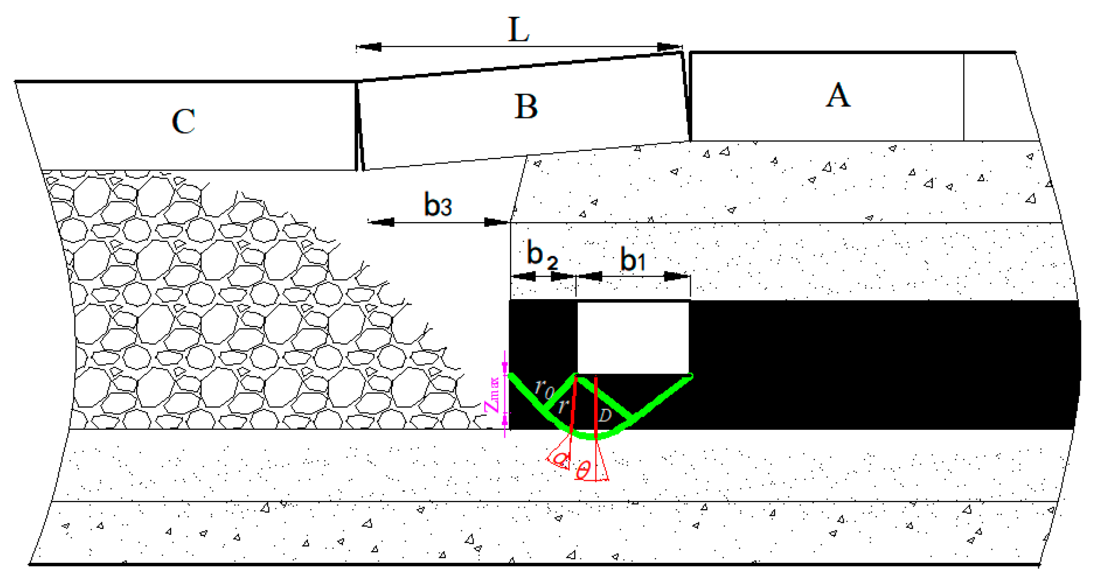
After the coal body is mined out, a structure similar to the masonry beam is formed by the fracture of the basic roof in the side of the goaf, as shown in
Figure 2. A partial load of the overlying strata is imposed on the coal pillars of adjacent working faces through the direct roof, and the load is further transferred to the floor by coal pillars. The failure occurs when the load on the floor exceeds its bearing limit. Based on the theory of coal pillar bearing load and the maximum failure depth of foundation in soil mechanics, the correlation between the coal pillar width and bottom failure depth is analyzed [
21].
According to White’s method of rock separation [
22], the load of coal pillar is composed of the gravity of rock block in a certain range above the roadway and coal pillar. The bearing load of coal pillars is obtained as follows:
where
h is the falling height, m,
;
b1 is the entry width, m;
b2 is the width of coal pillar, m;
b3 is the outer suspension distance of coal pillar and
b3 =
L −
b1 −
b2, m;
L is the length of lateral fracture in the basic roof, m;
q is the bearing load of coal pillar, kN/m
3;
γ1 is the bulk density of roof, kN/m
3;
φ1 is the shear angle, °;
M is the thickness of coal seam, °;
k is the fragmentation expansion coefficient, 1.1–1.5;
M is the strata thickness, m; and
β is the dip angle of the coal seam, °.
The relationship between the coal pillar and floor can be simplified as the relation between the foundation and foundation in soil mechanics. According to the foundation theory proposed by T.Kostecki, under the action of coal pillar load, the maximum failure depth of coal beneath is obtained as follows [
23]:
where
c is the cohesion of floor, kPa;
γ is the average volume force of floor, kN/m
3; and
φ is the internal friction of the floor, °.
Under the action of coal pillar abutment pressure, the depth of plastic zone formed in the entry floor can be obtained as follows [
24]:
Equation (4) can be obtained by substituting Equation (3) into Equation (2):
If
, the maximum failure depth of coal below the entry floor is obtained:
Equation (6) is obtained by substituting Equation (1) into Equation (5):
where
,
,
are correction factors and taken as 100; and
λ and
η are only related to the geomechanical parameters of the roof and floor.
From the above mechanical analysis, if (1) other parameters are determined, (2) sufficient strength is maintained in the coal pillar, and (3) the coal pillar can effectively transfer the roof load to the floor, the smaller the width of the coal pillar, the greater the failure depth of the bottom coal; the greater the width of the coal pillar, the smaller the failure depth of the bottom coal. After the failure, the bottom heave is formed along with the shear slip into the entry space. The greater the failure depth, the more coal bodies are involved in the floor heave, the larger the floor heave amount [
25]. The bottom heave further splits the bottom coal, which is conducive to resource recovery by the mine excavator loader.
3.2. Numerical Analysis of Floor Deformation and Failure
3.2.1. Numerical Modeling
Based on geological conditions of the roof and floor of the working face 8407 and the 15# coal seam, the
FLAC3D finite difference software (5.00, Itasca Consulting Group, Inc., Minneapolis, MN, USA) was used for modeling and analysis. Generally, mechanical parameters of coal rock measured in the laboratory are higher than the real value of engineering rock. Therefore, the measured value should be calibrated and assigned to the numerical calculation model, so as to ensure the results are closer to the actual engineering. Mechanical parameters of the coal rock provided in
Table 1 are calibrated by Equations (7) and (8) [
26,
27,
28,
29]:
where
σ1m is the triaxial strength (MPa);
σ3m is the confining pressure stress (MPa);
σci is the compressive strength (MPa);
σti is the tensile strength (MPa);
b = 0.51 is the index in the failure criterion, which controls the curvature of the triaxial curve;
σcm is the compressive strength (MPa);
σtm is the tensile strength (MPa); and
RMR (Relative Metabolic Rate) is the rock rating of Bieniawski. The subscript
i represents the laboratory intact rock, and m represents the engineering rock.
The shear strength parameters of rock mass are calibrated and calculated by Equation (9):
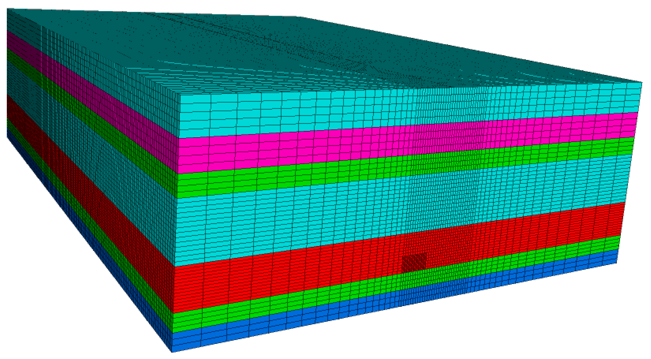
The numerical model size is 95 × 140 × 37.5 m, as shown in
Figure 3. It is assumed that each rock layer and coal seam belongs to the isotropic material. The waste rock in goaf is assumed to be an elastic material. The Mohr-Coulomb elastic-plastic model is used for the rock layer, and the Mohr-Coulomb strain softening model for the coal seam. The above calibrated mechanical parameters are used as the equivalent Mohr-Coulomb parameters to assign to the coal seam and rock layer of the model.
The horizontal zero displacement constraints are applied to the left and right sides of the model, and the vertical zero displacement constraint is applied to the bottom. Since the average burial depth of the coal seam is 360 m and the thickness of the above coal seam of the model is 24 m, the upper load is:
where
γ is the volume force of overlying strata, 25 kN/m
3; and
H is the burial depth of the coal seam, m.
3.2.2. Results and Analysis
After the adjacent working face is mined, a 4.05 × 5.2 m roadway is excavated along the roof near the goaf in each layer, with the thickness of the remaining bottom coal of 3 m. The width of the coal pillar between the roadway and the edge of the goaf is taken as 4, 5, 6, , 20 m. By changing the width of the coal pillar, the evolution law of the floor heave and the depth of the bottom coal failure along the goaf is analyzed.
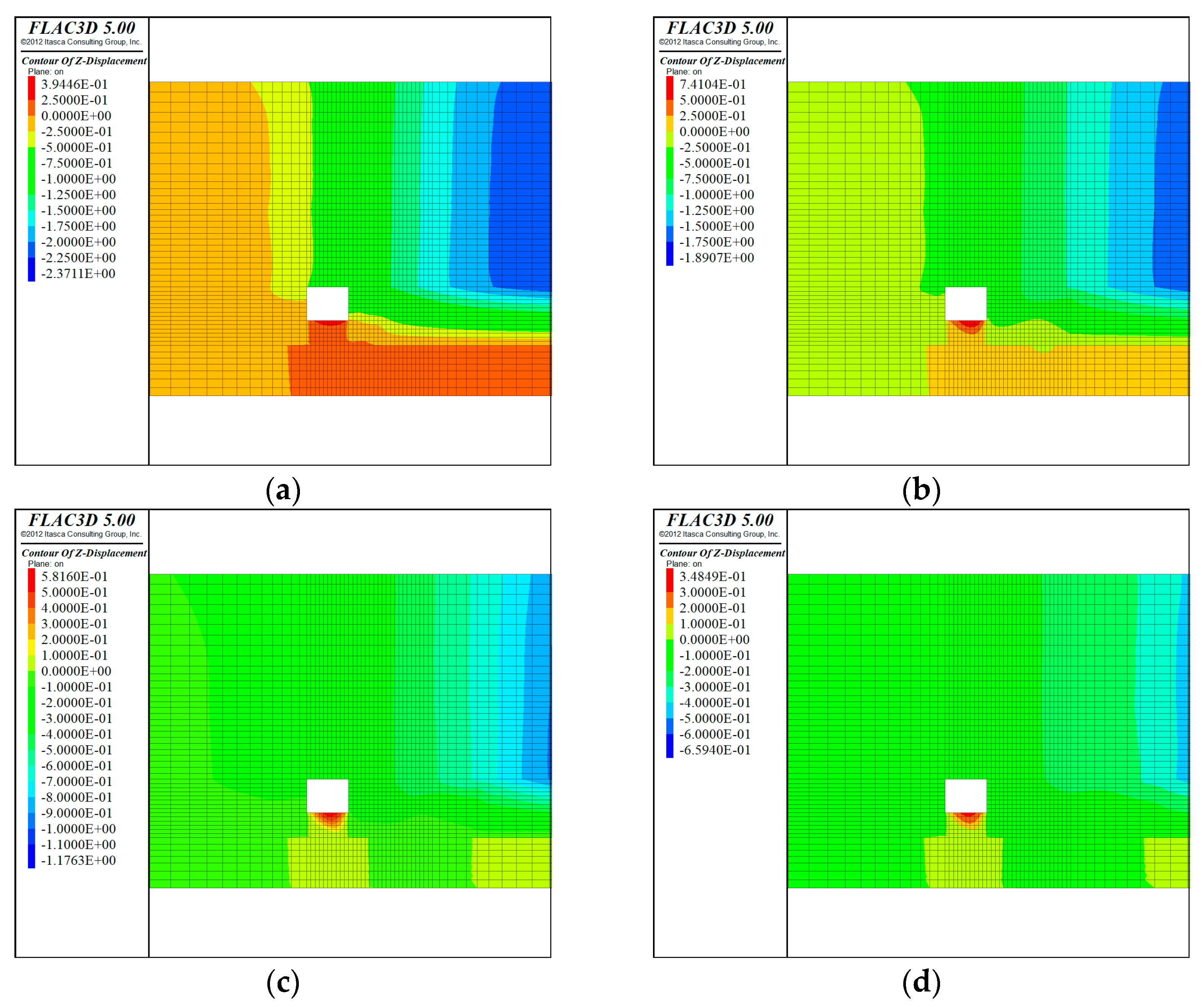
When the working face advances 40 m forward from the open-off cut, the vertical displacement cloud chart at 20 m in front of the working face is extracted, and the surrounding rock deformation of the roadway is shown in
Figure 4.
Figure 4 shows the displacement cloud map of the coal pillar with different widths. When the coal pillar is small, the vertical displacement of the roadway floor has an asymmetrical distribution, and the maximum floor heave is located near the side of the coal pillar. With the increase of the width of the coal pillar, the maximum floor heave gradually transfers to the middle of the roadway. It indicates that the stress of the roadway floor is not uniform, and the stress concentration near the coal pillar is high. With the increase of the coal pillar width, the stress of the roadway floor tends to be balanced.
The width of the coal pillar is taken as 4, 5, 6,
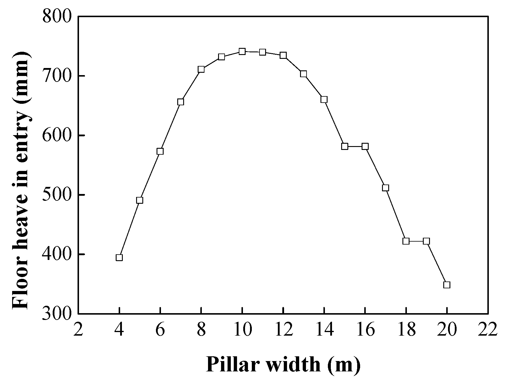
, 20 m, corresponding to the maximum displacement of the above position along the vertical direction of the floor in the goaf. The curve between the floor heave of the roadway and the width of the coal pillar is fitted, as shown in
Figure 5.
As shown in
Figure 5, the relationship between floor heave and pillar width of the gob-side roadway is approximately parabolic. As the width of coal pillar increases from 4 to 10 m, the amount of floor heave increases; as the width of coal pillar increases from 10 to 20 m, the amount of floor heave decreases; there is a wide distribution of the peak value of the curve, between 700 and 741.04 mm, the corresponding width of coal pillar changes from 8 to 13 m with a small changing range of floor heave.
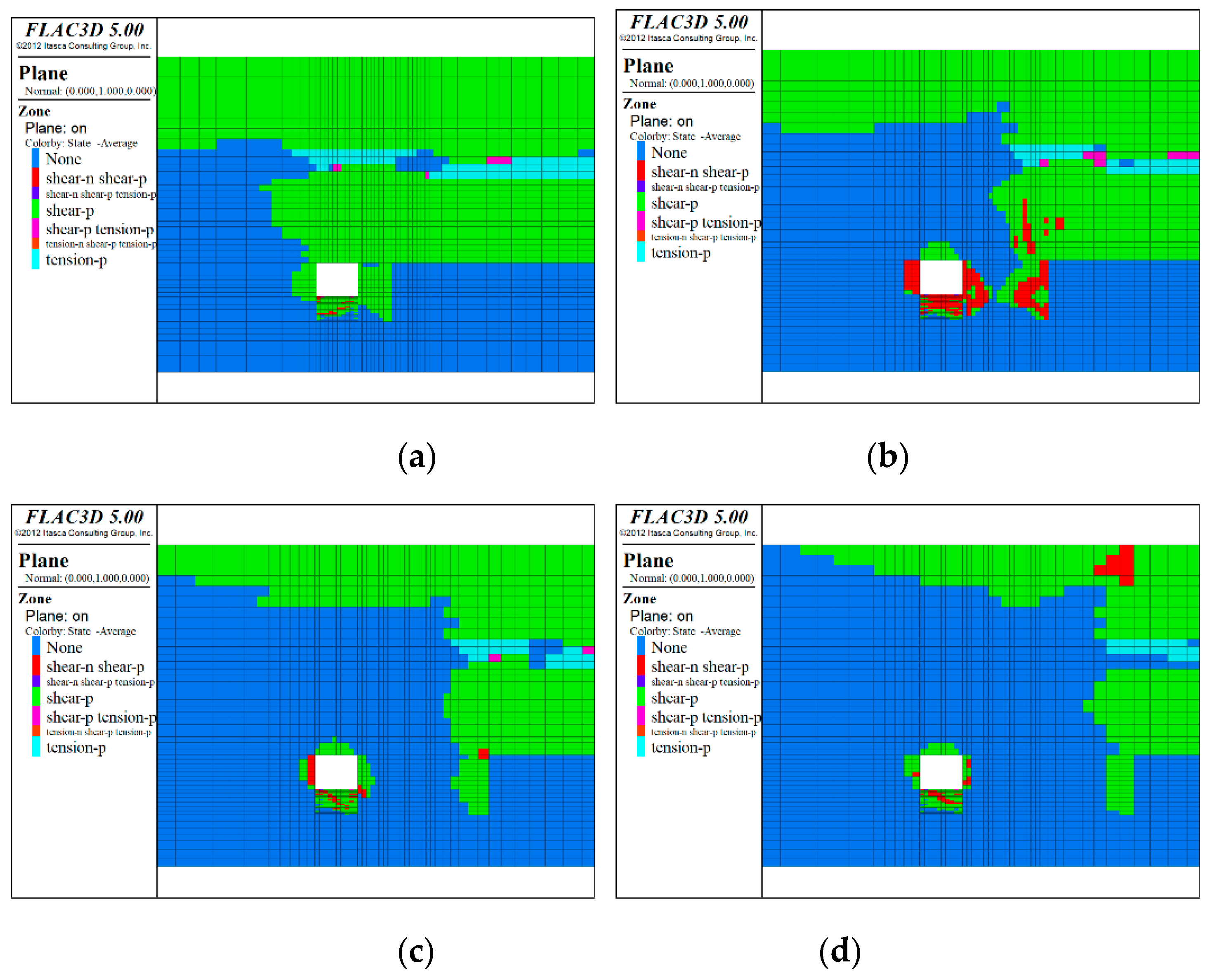
Figure 6 shows the failure modes of various parts of the strata (20 m ahead of the working face) when the coal pillars with different widths are used. The red area of the roadway floor subject to both tension and shear failure is regarded as the post-peak failure of the coal body. When the width of the coal pillar is small, the failure depth of the floor near the coal pillar is greater than that of the coal body; when the width of the coal pillar is large, the elastic-plastic zone appears in the coal pillar. With the increase of the width, the failure depth of the roadway floor decreases, and the elastic-plastic zone in the coal pillar increases.
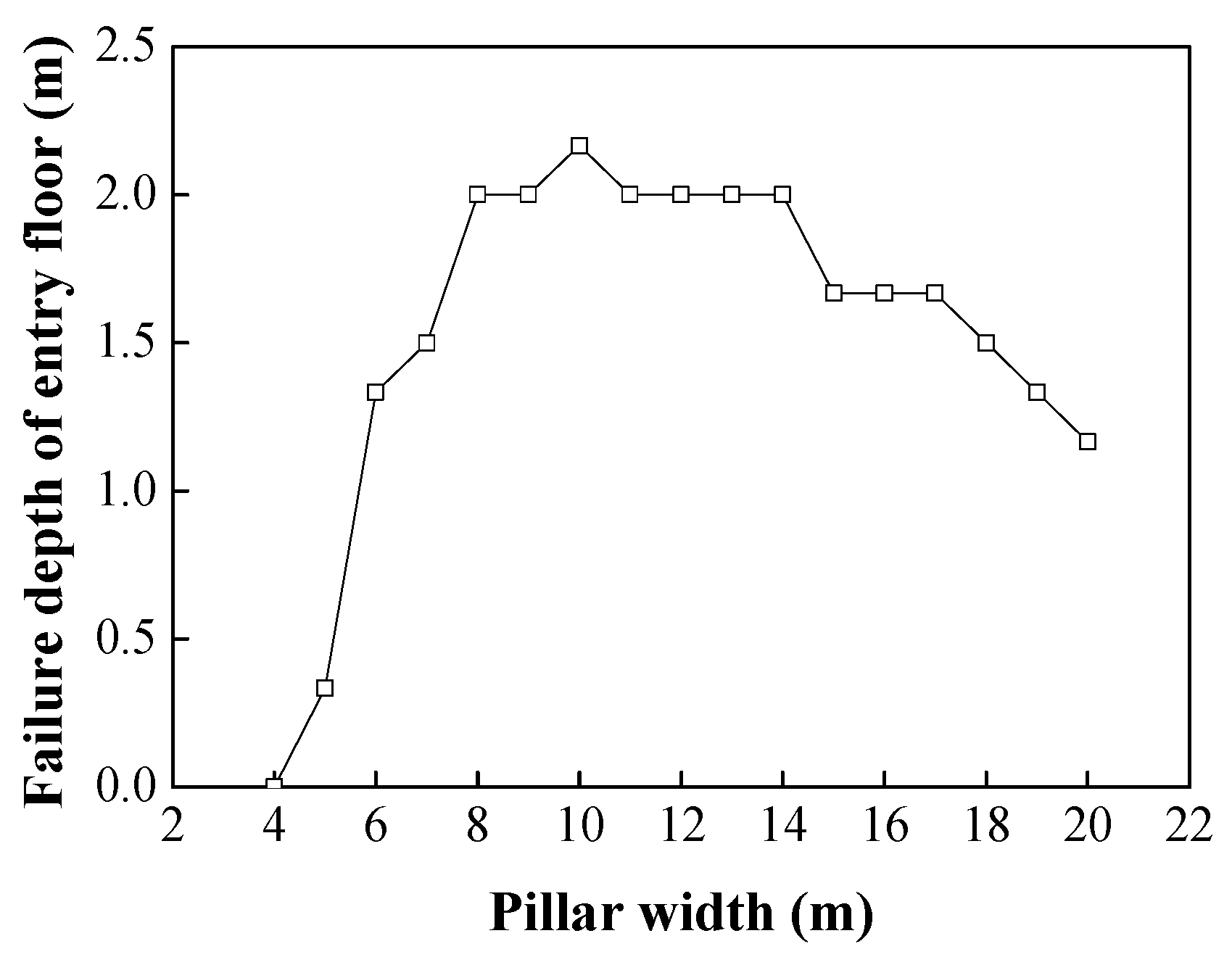
Figure 7 shows that the continuous failure depth of the roadway floor varies parabolically with the widening of coal pillars. When the width of coal pillars is less than 10 m, the failure depth of the floor increases with the increase of the width; when the width is more than 10 m, the failure depth of the floor decreases with the increase of the width. The peak value of the curve is widely distributed, ranging from 2–2.2 m with the corresponding width of the coal pillar from 8–13 m. In conclusion, with the change of the coal pillar width, the changing trend of the floor failure depth, and that of the floor heave is basically consistent.
Numerical results show that, when the width of the coal pillar is small, under the action of abutment pressure, all coal pillars enter the post-peak state, as shown in
Figure 6a. The ability of the coal pillar to transfer abutment pressure to the floor is weakened, the stress concentration of the roadway bottom coal is low, the failure depth is small, and the amount of floor heave is relatively small. As the width of the coal pillar increases, the elastic-plastic zone gradually appears in the coal pillar, as shown in
Figure 6b. This elastic-plastic zone is referred to as the stable zone in the literature [
30]. The stable zone can effectively transfer the lateral abutment pressure of the adjacent empty zone and the advance abutment pressure of the working face to the floor. When the stability zone is small, there is a small contact area with the floor and a relatively high-stress concentration on the floor, resulting in a large failure depth of the bottom coal and a large amount of bottom heave. As the width of the coal pillar increases, the thickness of the stable area inside the coal pillar increases (as shown in
Figure 6b–d), and as the contact area between the stable area and the bottom coal body increases, the stress concentration, the failure depth of the bottom coal, and the amount of floor heave decrease correspondingly.
The amount of floor heave and the floor failure depth is inversely related to the width of coal pillars. The smaller the width of coal pillars, the greater the floor failure depth. The more coal and rock mass is involved in the floor heave, the larger the amount of floor heave. These results are consistent with the abovementioned mechanical analysis.
4. Bottom Coal Recovery Technology
All mechanized operation is adopted for bottom coal recovery in the roadway. Firstly, the narrow coal pillar width is obtained by mechanical calculation and revised by numerical simulation, and then the final width is determined. Secondly, the mining excavator loader, transfer conveyor, and belt conveyor are selected, according to the geometric size of the roadway. According to the geometry size of the tunnel, the mining loader, transfer conveyor, and belt conveyor are selected. Due to the highly concentrated stress in the floor of the narrow coal pillar, the bottom coal is fully destroyed, and a large number of floor heaves are produced. Finally, the mining excavator loader is used to excavate and transport the broken bottom coal.
4.1. Determination of the Width of Narrow Pillars
To facilitate the recovery of bottom coal in the gob-side entry, the retained narrow coal pillars should be stable. In addition, these coal pillars should contribute to the destruction and heave of the bottom coal for mining excavator loaders. Equation (6) is modified according to the thickness
Dmax of the bottom coal to be recovered as follows:
where
b1 is the entry width, m;
b2 is the width of coal pillar, m;
L is the length of lateral fracture of the basic roof, m;
γ1 is the bulk density of the roof, kN/m
3;
φ1 is the shear angle, °;
M is the thickness of the coal seam, °;
k is the fragmentation expansion coefficient, 1.1–1.5;
c is the cohesion of floor, kPa;
γ is the average volume force of floor, kN/m
3;
φ is the internal friction of floor, °;
λ and
η are only related to the geomechanical parameters of the roof and floor,
,
and
ϑ are correction factors and taken as 100.
The width of the narrow coal pillar to be reserved is calculated and revised by numerical simulation, so as to determine the final width of the coal pillar.
4.2. Stability Controls of the Coal Pillar and Roadway Surrounding Rock
Due to the decrease in the pillar width and the increase in the stress of the pillar and the surrounding rock of the roadway, the support strength of the pillar and the surrounding rock of the roadway must be increased, especially the support strength of the surrounding rock at the side of the pillar [
31], so as to effectively control its stability.
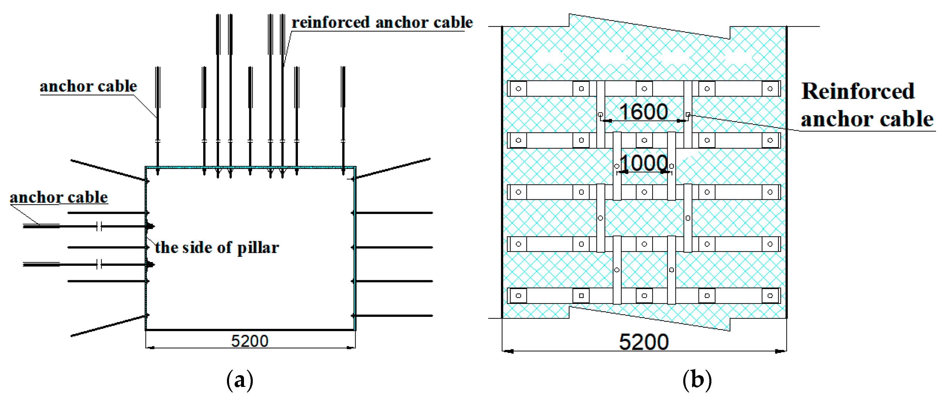
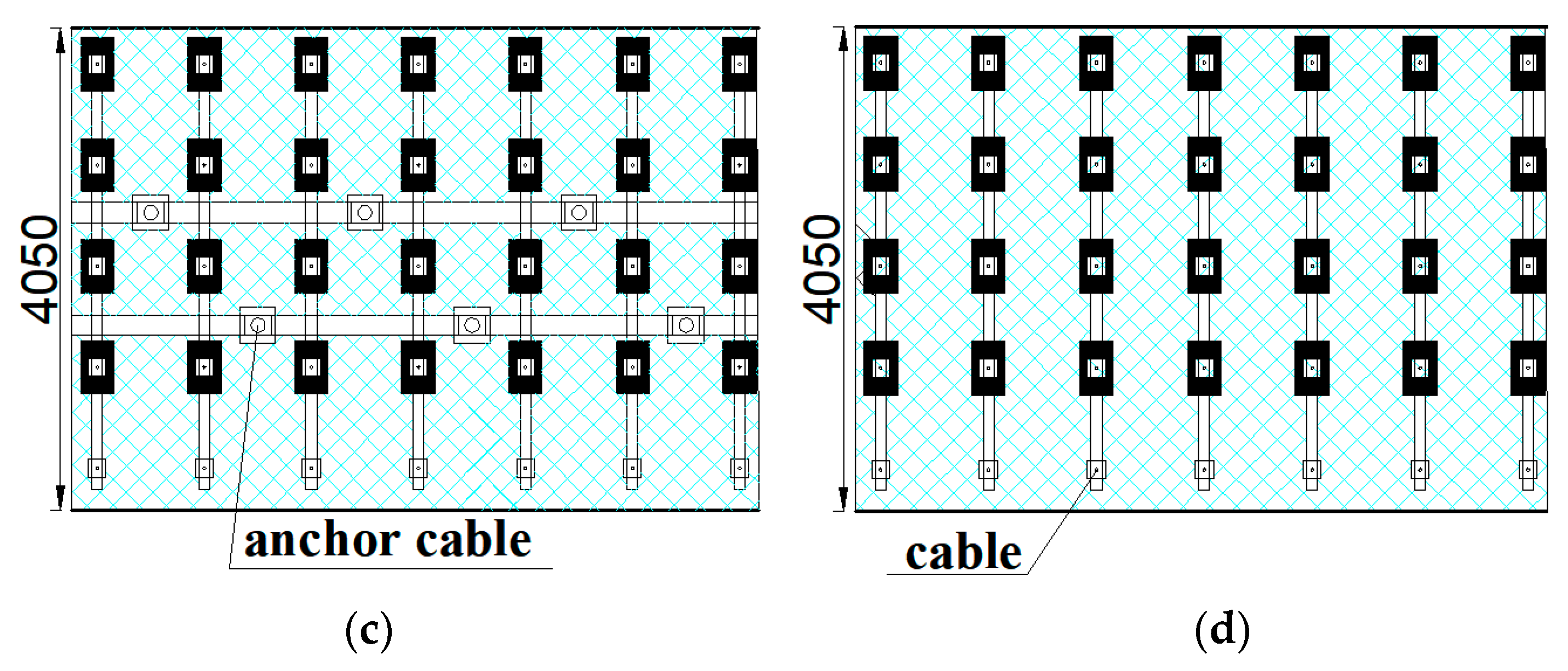
The combined support mode of "anchor cable + steel belt + metal mesh" is adopted in the roadway roof. The roof anchor cable is divided into two types: Ordinary anchor cable and reinforced anchor cable. The diameter of an ordinary anchor cable is not less than 17.8 mm, the length is not less than 50,000 mm, the spacing between anchor cables is not more than 1200 mm, the row spacing is not more than 1000 mm, the steel belt is used to connect the anchor bolts, and the metal mesh is laid. The diameter of reinforced anchor cable arranged in the middle of the roof is not less than 21.8 mm, the spacing is not more than 2000 mm, the row spacing is not more than 1000, and the length is not less than 70,000 mm.
The "bolt + anchor cable + steel ladder beam + metal mesh" combined support mode is adopted for the side roadway of coal pillars. Threaded steel bars with a diameter of not less than 20 mm, and a length of not less than 3000 mm are used as the bolt. The spacing of bolts is not more than 900 mm, and the row spacing is not more than 900 mm. The steel ladder beam is used to connect the bolt. Two rows of anchor cables are arranged in the middle of the roadway side, with a diameter of not less than 15.24 mm, a length of not less than 4000 mm, a spacing of not more than 1000 mm, and a row spacing of not more than 1000 mm. The anchor cables are connected by a steel ladder, and then the metal mesh is laid.
The “bolt + steel ladder + metal mesh" combined support method is adopted for the side roadway of solid coal. The diameter of the bolt is not less than 20 mm, the length is not less than 2000 mm, the spacing is not more than 1000 mm, and the row spacing is not more than 1000 mm. A steel ladder beam is used for connection and the metal mesh is laid.
4.3. Recovery Equipment for Bottom Coal
The mining loader is used to recover the bottom coal of the roadway. Consolidated or loose material similar to the soil strength is the working object of the mining excavator loader. The mining excavator loader has both excavation and loading functions. On the one hand, it can load loose coal and rock into its scraper conveyor; on the other hand, it has an excavation function for coal and rock which are in a post-peak state and close to the soil strength. Under the complex high-stress caused by narrow coal pillars, the bottom coal is broken, swelled, and further destroyed by pulling, shearing, and extrusion in the course of heave. Then, a discrete fractured structure is formed, which can be easily excavated and loaded by the excavator loader.
In the process of the bottom coal recovery, to ensure sufficient space for the safe passage, ventilation, and mechanical equipment, the size of the mining excavator loader should meet the following requirements:
where
X is the net height of roadway, m;
H is the height of mining excavator loader, m; ∆ is the predicted floor heave of the roadway, m;
Y is the net width of roadway, m; and
T is the width of mining excavator loader, m.
The recovery of bottom coal is carried out in the maintenance crew, and the digging capacity of mining excavator loader must be satisfied:
where
A is the excavation loading capacity of mining excavator loader, m
3/d;
T1 is the cross-section width of roadway, m;
Z is the recovery depth of bottom coal, m; and
Vf is the daily advance of working face, m.
The transportation capacity of the transshipment conveyor meets the following requirements:
where
E is the transport capacity of the transporter, t/h.
4.4. Failure State Analysis of Bottom Coal
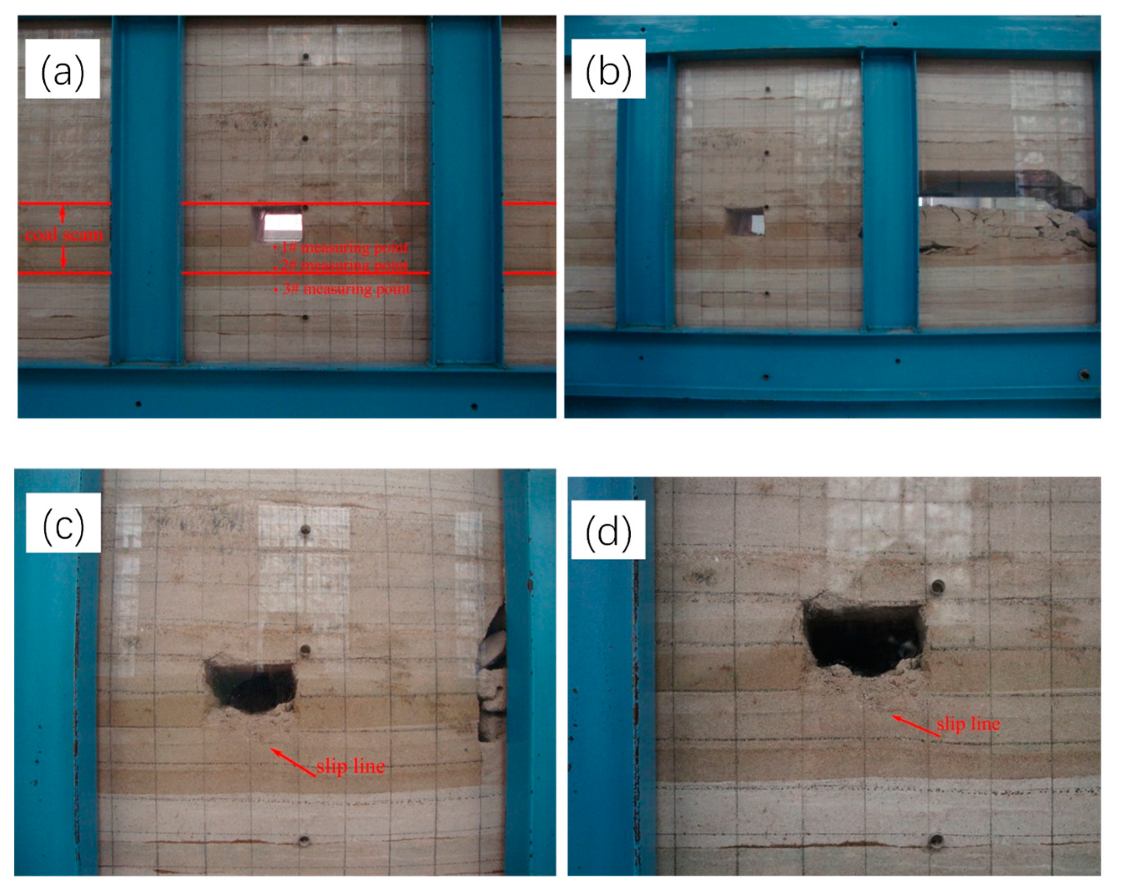
Through the physical simulation, the failure modes of the bottom coal with different width pillars are analyzed. Sand, gypsum, and calcium carbonate are taken as similar materials. According to the geomechanical parameters of roof and floor in the working face 8407, the model is built on the plane similar simulation platform at the geometric similarity ratio of 1:40. The size of the model is 2 × 0.3 × 2.5 m. After drying, a roadway of 100 × 125 mm is excavated along the roof in the model, and the thickness of the bottom coal is 75 mm. The longitude and latitude network of 60 × 50 mm is drawn on the model, and the monitoring points of 1#, 2#, and 3# are set at the intersection of longitude and latitude lines in the middle of the roadway floor, as shown in
Figure 8a.
After applying a 0.26 MPa load on the upper part of the model, the coal seam is gradually excavated from left to right, and the vertical displacement and failure depth of each measuring point on the floor are continuously collected by the total station, and the failure of the bottom coal at different depths in different stages is recorded timely.
As shown in
Figure 8 and
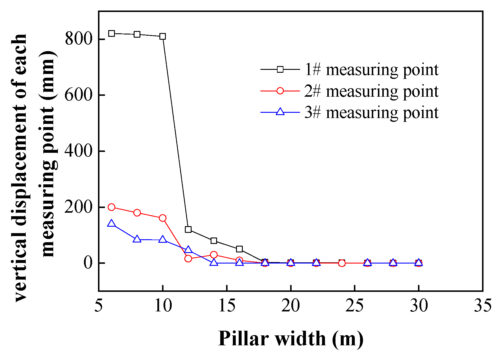
Figure 9, when the width of coal pillar is greater than 20 m, the vertical displacement of 1#, 2#, and 3# measuring points have little change; when the width of coal pillar is less than 20 m, the vertical displacement of each measuring point increases with the decrease of the width of coal pillar; when the width of coal pillar is reduced to 12 m, the vertical displacement of 1#, 2#, and 3# measuring points reaches 120, 60, and 46 mm, respectively, without the obvious failure of the floor (
Figure 8b). When the width of the coal pillar is reduced to 10 m, the vertical displacement of 1#, 2#, 3# measuring points increases rapidly to 810, 161, and 83 mm. An obvious slip line appears at the depth of 1000 mm near the bottom floor of the coal pillar side, and all the bottom coal above the slip line is in a broken and discrete state (
Figure 8c). All the bottom coal with a thickness of 1100 mm below the slip line enters the post-peak state, and the cohesion is close to 0. When the width of coal pillar decreases from 10 to 6 m, the displacement of measuring point 1# increases to 820 mm with a slow growth rate, while the vertical displacement of measuring point #2 and #3 increases to 200 and 140 mm, respectively, with a fast growth rate and a further increase in the depth of bottom coal failure (
Figure 8d).
In summary, when the pillar width is reduced to 10 m, the failure depth and floor heave of roadway bottom coal increase rapidly, and there are obvious slip lines in the floor. The bottom coal above the slip line is all in a broken and discrete state, and the bottom coal with a certain depth below the slip line is also in the post-peak state, which is conducive to the excavation and recovery of mining excavator.
5. Engineering Application
5.1. Determination of Coal Pillar and Roadway Support Parameters
According to the requirements of pedestrian and ventilation on the roadway section, the clear section height of the return air roadway in the 8407 working face needs to reach 4 m, and the width needs to reach 4 m, so the bottom coal remains 3 m. The coal seam thickness is
M = 5 m. Since the periodic weighting step of the basic roof is about 20 m, so the lateral fracture length of the basic roof is
L = 20 m, gangue expansion coefficient in the goaf is
k = 1.2, roof caving angle is
φ3 = 48°, roof bulk density is
γ1 = 25 kN/m
3, the dip angle of the coal seam is
β = 8°, the bulk density of the coal seam is
γ2 = 15 kN/m
3, and the internal friction angle of the coal seam is
φ2 = 26°. Considering the other constraints, the bottom coal to be recovered is
Dmax = 2 m. According to Equation (14), the width of the coal pillar is calculated as 9.4 m. The parameters of the numerical simulation experiment in
Section 3.2 are all taken from the working face 8407. The calculation results show that the coal body with a width of 10 m can be damaged by leaving a coal pillar with a width of about 2 m on the bottom plate, resulting in a floor heave of about 811 mm, and the actual width of the coal pillar is finally determined to be 10 m.
5.2. Roadway Support Schemes
Coal pillars with a width of 10 m are reserved between the air return roadway of the working face 8407 and the goaf. The roof is supported by a full anchor cable. The side roadway of the coal pillar is supported by the combination of the anchor bolt and anchor cable. The supporting parameters are shown in
Figure 10.
The joint support of "anchor cable + W steel belt + metal mesh” is used for the roadway roof. Five anchor cables are arranged in each row, the specification of an anchor cable is
φ 21.8 × 5,200 mm, connected by the W-shaped steel belt, the spacing of anchor cables is 1150 mm, the row spacing is 900 mm; in the middle area of the roadway roof, two adjacent rows of anchor cables are added, the spacing of anchor cables is alternately arranged by 1000 and 1600 mm, the specification of an anchor cable is
φ 21.8 × 7300 mm, and each anchor cable is matched with a 29# U-shaped steel with a length of 1200 mm as a tray, and the top plate is laid with a 1100 × 5600 mm longitude and latitude metal mesh. The specific layout parameters are shown in
Figure 10b.
The side wall of the coal pillar roadway is supported by "bolt + anchor cable + reinforced ladder beam + metal mesh". Five bolts (
φ 20 × 3000 mm) are arranged in each row, with a spacing of 850 mm and a row spacing of 900 mm, which are connected by the reinforced ladder beam; two rows of anchor cables are arranged in the middle part of the roadway, with a specification of
φ 17.8 × 4200 mm, a spacing of 1800 mm, and a row spacing of 950 mm, which are connected by a reinforced ladder beam, and a 1100 × 5600 mm longitude and latitude metal mesh are laid, as shown in
Figure 10c.
The solid coal side roadway is supported by the joint support method of "bolt + reinforced ladder beam + metal mesh". Five bolts (
φ 20 × 3000 mm) are arranged in each row, with a spacing of 850 mm and a row spacing of 900 mm. They are connected by the reinforced ladder beam, and a 1100 × 5600 mm metal mesh is laid, as shown in
Figure 10d.
5.3. Selection of Excavation and Transportation Equipment
The estimated volume of the bottom heave is ∆ = 1 m. According to Equation (15), the height and width of the mining excavator loader’s fuselage are determined as H ≤ 2500 mm and T ≤ 2000 mm. The maximum daily advance of fully mechanized caving in the working face of coal seam 15 is 6 m. Since the recovery of bottom coal is carried out in the maintenance crew, to avoid the interaction with other work in the maintenance crew, the working time of bottom coal recovery does not exceed half of the working time of the maintenance crew. The digging capacity A ≥ 60 m3/d of the excavator loader is calculated according to Equation (16).
According to the above parameters, the existing ZWY-80/45L mining excavator loader and DZQ80/35/11 transporter are selected. The ZWY-80/45L mining excavator loader is 5.8 × 1.7 × 2.25 m in shape size (long × wide × high), with the loading capacity of 80 m3/h. The transport capacity of the DZQ80/35/11 transfer conveyor is 300 t/h. When the coal density is 1.5 t/m3, the transporting capacity is converted to 200 m3/h, which is larger than the excavating capacity of the excavator loader and meets the supporting requirements.
5.4. Application Effects
5.4.1. Measurement of Stability Control Effect of Coal Pillars and Roadway Surrounding Rock
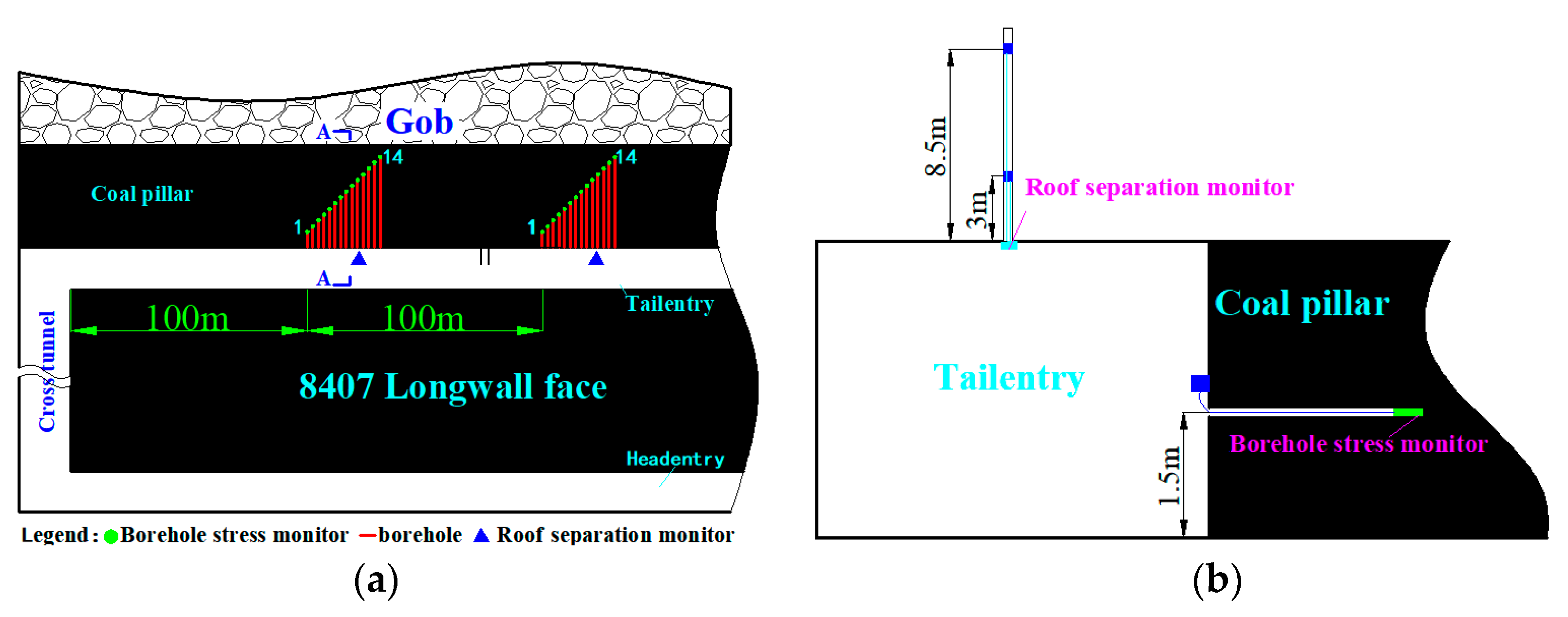
To accurately grasp the stability of the surrounding rock and coal pillar of the air return roadway in the working face 8407,Ⅰ# and Ⅱ# underground pressure measuring stations are respectively arranged at 100 and 200 m away from the open-cut hole in the roadway. In each measuring station, 14 boreholes are constructed at the position of 1.5 m from the side of the coal pillar to the bottom slab. The depth of boreholes is 1.5, 2, 2.5, ⋯, 8 and 8.5 m in turn, and the spacing between adjacent boreholes is 0.2 m. A GYW60W surrounding rock stress sensor is installed at the bottom of each borehole to monitor the stress evolution law of different depth positions in the coal pillar, so as to judge the stability of the coal pillar. At the same time, 1 GUD300W roof displacement sensor is installed on the roof of each measuring station to monitor the internal separation of the roof strata. The layout of the measuring station is shown in
Figure 11.
5.4.2. Analysis of Measured Results
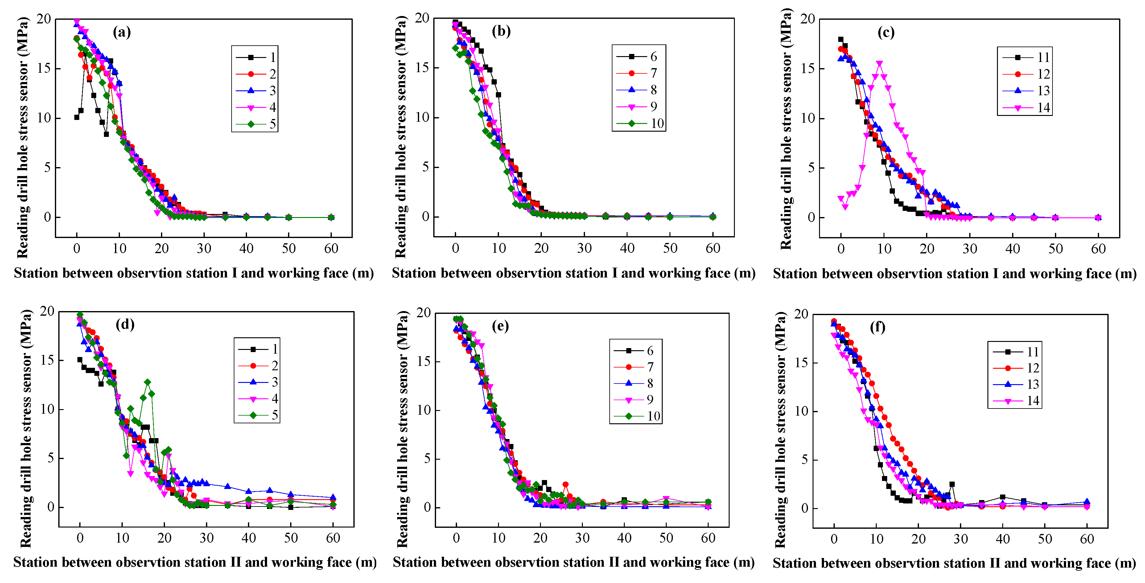
The surrounding rock stress sensor can automatically collect and store the surrounding rock stress data, and the data acquisition frequency is 30 times/h. The relationship curve between the data collected by the borehole stress sensor of each station and the distance between the station and the working face is drawn in the coordinate system, as shown in
Figure 12.
As shown in
Figure 12a, when the distance betweenⅠ# measuring station and the working face is more than 20 m, the change range of stress at different positions in the coal pillar is small; when the distance between the two is less than 20 m, the number of No. 2–13 stress meters in the coal pillar keeps climbing as the distance between the measuring station and working face continues to shrink, and the value of No. 4 borehole stress meters finally reaches 19.8 MPa; when the distance between the working face and measuring station decreases from 8 to 7 m, the reading of the No. 1 stress meter decreases from 16.8 to 8.4 MPa. As the working face continues to advance, the stress rises again to 16.5 MPa. When the distance from the working face to the measuring station decreases from 2 to 0 m, the stress decreases from 16 to 10.1 MPa. It can be seen that the coal body at a 1.5 m position in the coal pillar still has a constant bearing capacity under the support of bolt and anchor cable; when the distance from the measuring station to the working face is 9 m, the reading of the No.14 borehole stress meter reaches the maximum value of 15.6 MPa. With the advance of the working face, the stress value decreases rapidly, and finally drops to 2 MPa. It can be seen that the location of the No. 14 borehole stress meter has entered a broken state and almost lost its bearing capacity; while the final readings of the No. 2–13 stress meter are all between 16–19.8 MPa. Therefore, the coal body between No. 2–13 stress meters in the coal pillar is in an elastic state in the whole process, with a width of 6 m, accounting for 60% of the total width of the coal pillar. After the coal body at the location of the No. 1 borehole is damaged, its participating strength is further improved under the support of the anchor bolt and anchor cable, with a certain bearing capacity, which is conducive to the stability of the coal pillar and the surrounding rock of the roadway.
As shown in
Figure 12b, when the distance between theⅡ# measuring station and working face is more than 24 m, the stress level in different positions of the coal pillar is relatively low; when the distance between them is less than 24 m, with the continuous advance of the working face, all stress meter readings in the coal pillar generally show a continuous increase. When the working face is pushed to the position of the measuring station, all stress meter readings reach the maximum, and the readings of the No. 1–14 stress meter is in the range of 15.1–19.4 MPa. It can be seen that the coal body between No. 1–14 stress meters in the coal pillar is always in an elastic state and has enough bearing capacity, and the width of this part of the coal body is 8 m, accounting for 80% of the total width of the coal pillar.
As shown in
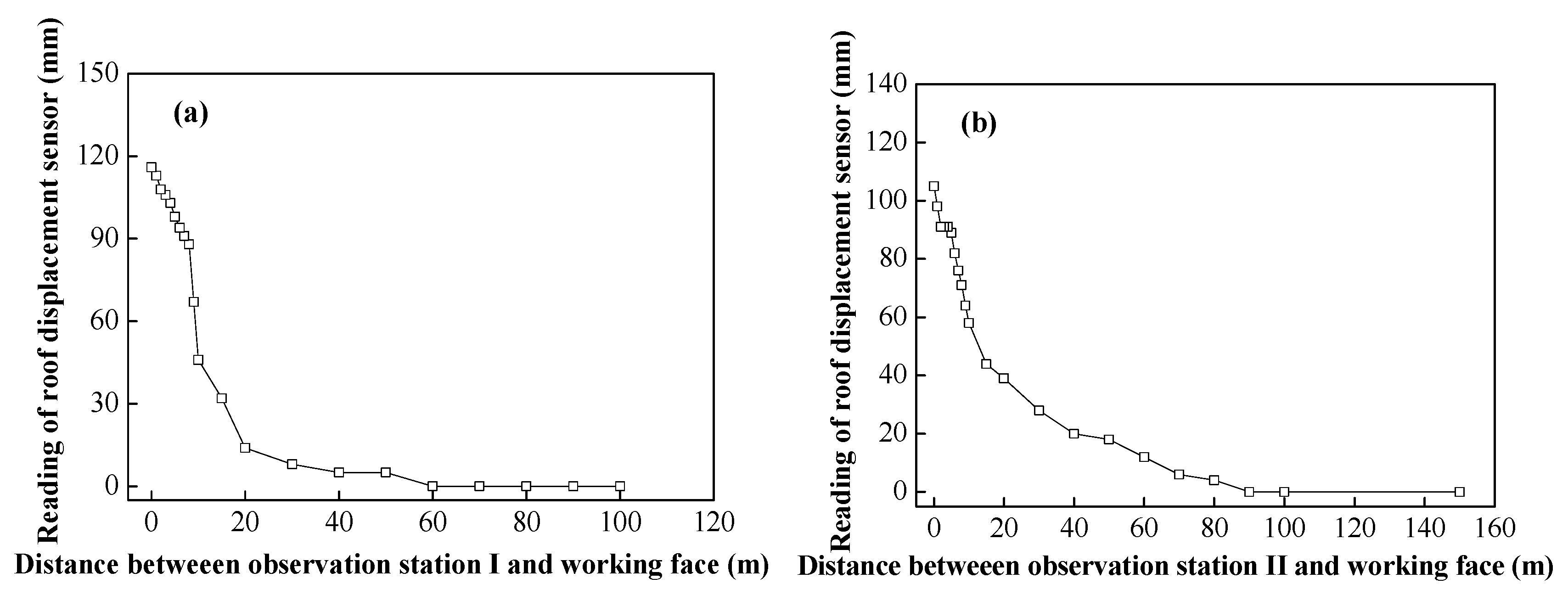
Figure 13, the displacement of strata in the roof of I# and II# stations increase gradually with the advance of the working face. The maximum displacement of I # stations is 116 mm, and that of II# stations is 105 mm. The displacement of the roadway roof is small, and the roof stability is good.
As shown in
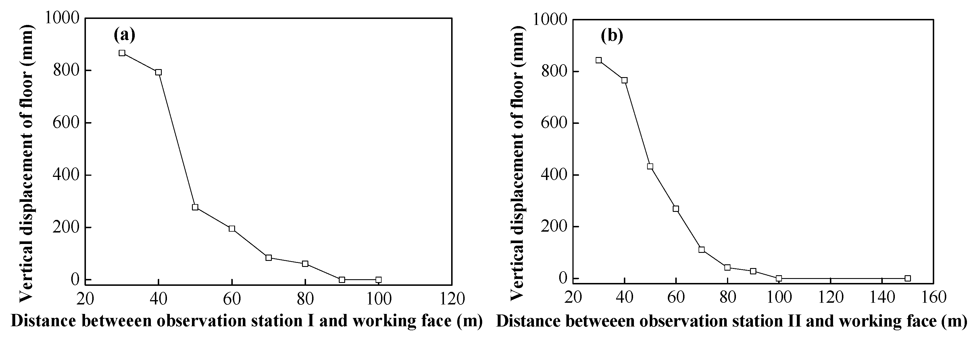
Figure 14, the vertical displacement of the floor of I# and II# stations increase with the decrease of the distance from the station to the working face. When I# station is 30 m away from the working face, the floor displacement reaches 867 mm, and when II# station is 30 m away from the working face, the floor displacement reaches 843 mm, and the deformation of the floor increases continuously, which is conducive to the recovery of the bottom coal.
Due to the influence of mining, some coal bodies on sides of the coal pillar are damaged; the damaged area near the goaf has lost its bearing capacity, while the damaged area near the working face still has a certain bearing capacity under the action of the anchor bolt and cable support. During the whole service period, the coal body with a width of not less than 6 m in the interior of the coal pillar is always in an elastic state, so that the stability of the coal pillar and surrounding rock of the roadway are guaranteed. Under the support of a high-strength full anchor cable, the displacement in the roof strata is small and the stability is good. With the increase of the vertical displacement of the coal body in the roadway floor, the inner part of the coal body is destroyed continuously, which can be recovered by the mining excavator.
5.4.3. Recovery Effect of Roadway Bottom Coal
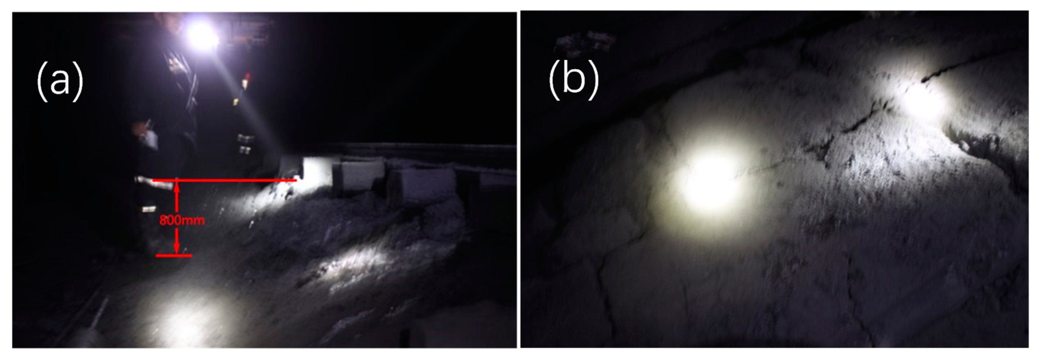
Floor heave occurs after the formation of the return airway is formed in the working face 8407. With the advance of working face, a serious floor heave caused by the mining appears in the roadway section.
Figure 15 shows the floor deformation of the roadway section which is 25–40 m in front of the working face. The floor heave of this section is about 800 mm, resulting in the cracking and fragmentation of the bottom coal.
The maximum daily advance of the working face is 6 m/d and the advance support of the working face is 25 m. The bottom coal recovery is carried out outside the advance support roadway of the working face. To ensure sufficient expansion and failure of coal in the entry, facilitating the excavation and loading recovery of mining excavator loader, the daily schedule of bottom coal recovery is designed as 10 m/d, considering the recovery work stagnation caused by the failure of the bottom coal recovery equipment and many other constraints.
During the bottom coal recovery, the shallow coal body (about 1 m) is seriously damaged in the spallation state under the complex stress environment formed by narrow coal pillars. The failure depth of the bottom coal near the coal pillar reaches 1.2 m (as shown in
Figure 16a), while the failure depth of the side near the coal body is less than 0.9 m, which can be easily picked up and merged by the mining loader. The bottom coal from 1.2 to 2.1 m is also in the post-peak state, which requires a certain digging force before further recovery. The bottom coal below 2.1 m has a good integrity and is difficult to dig, so the bottom coal with a thickness of 2.1 m is recycled.
Figure 16b shows the recovery site of the bottom coal by a mining excavation loader.
The length of working face 8407 is 1177 m, the coal pillar is reduced from 20 to 10 m, the output is increased by 67800 t, and the output of bottom coal in the entry is increased by 15044 t. In this way, considerable economic and social benefits are obtained for enterprises. This method also provides a new way to improve the recovery resource rate of working face for the thick coal seam.
6. Conclusions
(1) Through theoretical research, numerical calculation, and similar simulation, the correlations between the deformation failure of the bottom coal and the width of the coal pillar are revealed. When the strength of the coal pillar is sufficient, the failure depth of the bottom coal increases with the decrease of the coal pillar width. The amount of floor heave is negatively correlated with the failure depth of bottom coal. The smaller the width of the coal pillar, the greater the failure depth of bottom coal.
(2) On the basis of the above analysis, a recovery method of the bottom coal with thick coal seams in the gob-side entry is proposed based on the effect of narrow pillar heave. Since floor heave can be caused by the narrow pillars easily, the reasonable width narrow pillars can be set in the gob-side entry to promote the expansion and fracture of the bottom coal with a certain thickness, and then the mining excavator loader can be used to perform the excavation and loading. Finally, the mechanization and resource recovery of the bottom coal in the gob-side entry can be realized.
(3) To improve the stability of the surrounding rock of the narrow coal pillar in the gob-side entry, the combined support of "bolt + anchor cable + steel ladder beam + metal mesh" is proposed for the side wall of the coal pillar, and the combined support of "anchor cable + W steel belt + metal mesh" is adopted for the roof. As a result, the stability of the surrounding rock of the narrow coal pillar and the roadway is effectively maintained.
(4) The recovery method of the bottom coal with thick coal seams in the gob-side entry based on the heave effect of narrow coal pillars has been successfully applied to the working face 8407 of the No. 5 Coal Mine of Yangquan Mining Group. The application results show that there is a great stability of the surrounding rock and narrow coal pillar; the maximum subsidence of the roof is only 116 mm, the maximum floor heave of the floor is 867 mm; the width of coal pillar in the gob-side entry is reduced from 20 to 10 m, the recovered thickness of bottom coal seams in the gob-side entry is 2.1 m, and the recovered coal resource is about 82844 t, achieving remarkable economic and social benefits.
Author Contributions
Conceptualization, K.W. and Y.H.; Data curation, K.W.; Formal analysis, K.W.; Methodology, K.W., H.G., Y.Q., J.L., S.O. and W.L.; Writing—original draft, K.W.; Funding acquisition, Y.H.; Project administration, Y.H.; Resources, Y.H. and W.Z.; Investigation, H.G., W.Z., Y.Q. and J.L.; Writing—review & editing, H.G., Y.H., W.Z., Y.Q., J.L., S.O. and W.L. All authors have read and agreed to the published version of the manuscript.
Funding
This research was funded by [the National Key R&D Program of China] grant number [2018YFC0604705], [the National Natural Science Foundation of China] grant number [51774269], and [the Natural Science Foundation of Jiangsu Province, China] grant number [BK20190031].
Conflicts of Interest
The authors declare no conflict of interest.
References
- Yuan, Z.; Zhen, C.; Lei, W.; Gao, W. The green behavioral effect of clean coal technology on China’s power generation industry. Sci. Total Environ. 2019, 675, 286–294. [Google Scholar]
- Li, J.; Huang, Y.; Chen, Z.; Zhang, J.; Jiang, H.; Zhang, Y. Characterizations of macroscopic deformation and particle crushing of crushed gangue particle material under cyclic loading: In solid backfilling coal mining. Powder Technol. 2019, 343, 159–169. [Google Scholar] [CrossRef]
- Wang, J. Key technology for fully-mechanized top coal caving with large mining height in extra-thick coal seam. J. China Coal Soc. 2013, 38, 2089–2098. [Google Scholar]
- Dai, J.; Shan, P.; Zhou, Q. Study on Intelligent Identification Method of Coal Pillar Stability in Fully Mechanized Caving Face of Thick Coal Seam. Energies 2020, 13, 305. [Google Scholar] [CrossRef]
- Huang, Y.; Li, J.; Ma, D.; Gao, H.; Guo, Y.; Ouyang, S. Triaxial compression behaviour of gangue solid wastes under effects of particle size and confining pressure. Sci. Total Environ. 2019, 693. [Google Scholar] [CrossRef]
- Hu, J.; He, M.; Wang, J.; Ma, Z.; Wang, Y.; Zhang, X. Key Parameters of Roof Cutting of Gob-Side Entry Retaining in a Deep Inclined Thick Coal Seam with Hard Roof. Energies 2019, 12, 934. [Google Scholar] [CrossRef]
- Guo, W.; Bai, E.; Yang, D. Study on the technical characteristics and index of thick coal seam high-intensity mining in coalmine. J. China Coal Soc. 2018, 43, 2117–2125. [Google Scholar]
- Tan, Y.; Ma, Q.; Zhao, Z.H.; Gu, Q.H.; Fan, D.Y.; Song, S.L.; Huang, D.M. Cooperative bearing behaviors of roadside support and surrounding rocks along gob-side. Geomech. Eng. 2019, 18, 439–448. [Google Scholar]
- Faria, S.C.; Bieniawski, Z.T. Floor design in underground coal mines. Rock Mech. Rock Eng. 1989, 22, 249–271. [Google Scholar] [CrossRef]
- Zhong, Z.; Tu, Y.; Liu, X. Occurrence Mechanism and Control Technology of the Floor Heave Disaster for Soft-rock Tunnel. Disaster Adv. 2012, 5, 987–992. [Google Scholar]
- Mo, S.; Ramandi, H.L.; Oh, J.; Masoumi, H.; Canbulat, I.; Hebblewhite, B.; Saydam, S. A new coal mine floor rating system and its application to assess the potential of floor heave. Int. J. Rock Mech. Min. Sci. 2020, 128, 104241. [Google Scholar] [CrossRef]
- Mo, S.; Tutuk, K.; Saydama, S. Management of floor heave at Bulga Underground Operations—A case study. Int. J. Min. Sci. Technol. 2019, 29, 73–78. [Google Scholar] [CrossRef]
- Wang, M.; Zheng, D.; Wang, K.; Li, W. Strain energy analysis of floor heave in longwall gateroads. R. Soc. Open Sci. 2018, 6, 180691. [Google Scholar] [CrossRef]
- Jessu, K.V.; Kostecki, T.R.; Spearing, A.J.S.; Zhang, J. Influence of varying bedding thickness of underclay on floor stability. Int. J. Min. Sci. Technol. 2017, 27, 517–523. [Google Scholar] [CrossRef]
- Kostecki, T.; Spearing, A.J.S. Influence of backfill on coal pillar strength and floor bearing capacity in weak floor conditions in the Illinois Basin. Int. J. Rock Mech. Min. 2015, 76, 55–67. [Google Scholar] [CrossRef]
- Jia, H.; Wang, L.; Fan, K.; Peng, B.; Pan, K. Control Technology of Soft Rock Floor in Mining Roadway with Coal Pillar Protection: A case study. Energies 2019, 12, 3009. [Google Scholar] [CrossRef]
- Perry, K.; Bradley, J.; Unrug, K.; Klimek, M. Mitigation of floor heave in West Kentucky Coal Mine. Int. J. Min. Sci. Technol. 2016, 26, 521–525. [Google Scholar] [CrossRef]
- Wang, J.; Guo, Z.; Yan, Y.; Pang, J.; Zhao, S. Floor heave in the west wing track haulage roadway of the Tingnan Coal Mine: Mechanism and control. J. Min. Sci. Technol. 2012, 22, 295–299. [Google Scholar] [CrossRef]
- Ma, J. Analysis of the effects of weak floor strata onlongwall face stability using finite element modeling. J. Coal Sci. Eng. (China) 2001, 01, 1–8. [Google Scholar]
- Yuan, Y.; Tu, S.; Wu, Q.; Ma, X.; Tu, H.; Bai, Q. Recovery technology in the roadway with slope changing and bottom mining methods of coal near the floor in the face end area of large mining height fully mechanized face. J. China Coal Soc. 2010, 35, 1594–1598. [Google Scholar]
- Huang, Y.; Li, J.; Song, T.; Kong, G.; Li, M. Analysis on Filling Ratio and Shield Supporting Pressure for Overburden Movement Control in Coal Mining with Compacted Backfilling. Energies 2017, 10, 31. [Google Scholar] [CrossRef]
- Zha, W.; Li, X.; Hua, X.; Wu, T.; Yin, S. Impact and application on narrow coal pillar for roadway protecting from fracture position of upper roof. J. China Coal Soc. 2014, 39, 332–338. [Google Scholar]
- Terzaghi, K.; Xu, Z. Theoretical Soil Mechanics; Geological Publishing House: Beijing, China, 1960; pp. 125–219. [Google Scholar]
- Qian, M.; Shi, P.; Xu, J. Ground Pressure and Strata Control; China University of Mining and Technology Press: Xuzhou, China, 2013. [Google Scholar]
- Wang, K.; Hao, B.; Zhang, P.; Qiao, Y. Floor heave control mechanism of inner interlocked gas tail road based on reinforced concrete pillar. J. China Coal Soc. 2016, 41, 2181–2187. [Google Scholar]
- Das, A.J.; Mandal, P.K.; Paul, P.S. Assessment of the Strength of Inclined Coal Pillars through Numerical. Rock Mech. Rock Eng. 2019, 52, 3691–3717. [Google Scholar] [CrossRef]
- Kumar, A.; Waclawik, P.; Singh, R.; Ram, S.; Korbel, J. Performance of a coal pillar at deeper cover: Field and simulation studies. Int. J. Rock Mech. Min. 2019, 113, 322–332. [Google Scholar] [CrossRef]
- Jaiswal, A.; Shrivastva, B.K. Numerical simulation of coal pillar strength. Int. J. Rock Mech. Min. 2009, 46, 779–788. [Google Scholar] [CrossRef]
- Huang, Y.; Li, J.; Teng, Y.; Dong, X.; Wang, X.; Kong, G.; Song, T. Numerical Simulation Study on Macroscopic Mechanical Behaviors and Micro-Motion Characteristics of Gangues under Triaxial Compression. Powder Technol. 2017, 320, 668–684. [Google Scholar] [CrossRef]
- Wang, K.; Hao, B.; Zhang, P.; Qiao, Y. Determination mechanism of narrow coal pillar width in fully mechanized caving face with high gas based on seepage mechanics. China Coal 2017, 43, 47–51. [Google Scholar] [CrossRef]
- Chen, Z.; Li, Y.; Yang, R.; Zhu, Y.; Lin, H.; Xiao, C. Non-uniform deformation mechanism and support technology of narrow coal pillar roadway. J. China Coal Soc. 2018, 43, 1847–1857. [Google Scholar]
Figure 1.
Coal mine site.
Figure 1.
Coal mine site.
Figure 2.
Bottom coal failure model in the gob-side entry.
Figure 2.
Bottom coal failure model in the gob-side entry.
Figure 3.
The numerical model.
Figure 3.
The numerical model.
Figure 4.
Vertical displacement of coal pillars with different widths. (a) Coal pillar of 4 m wide; (b) coal pillar of 10 m wide; (c) coal pillar of 15 m wide; (d) coal pillar of 20 m wide.
Figure 4.
Vertical displacement of coal pillars with different widths. (a) Coal pillar of 4 m wide; (b) coal pillar of 10 m wide; (c) coal pillar of 15 m wide; (d) coal pillar of 20 m wide.
Figure 5.
The relationship between the floor heave and pillar width in the gob-side roadway.
Figure 5.
The relationship between the floor heave and pillar width in the gob-side roadway.
Figure 6.
Failure depth of floor at different widths of coal pillars. (a) Coal pillar of 4 m wide; (b) coal pillar of 10 m wide; (c) coal pillar of 15 m wide; (d) coal pillar of 20 m wide.
Figure 6.
Failure depth of floor at different widths of coal pillars. (a) Coal pillar of 4 m wide; (b) coal pillar of 10 m wide; (c) coal pillar of 15 m wide; (d) coal pillar of 20 m wide.
Figure 7.
The relationship between the continuous failure depth of the roadway floor and the coal pillar width.
Figure 7.
The relationship between the continuous failure depth of the roadway floor and the coal pillar width.
Figure 8.
Deformation and failure of the entry floor under different width coal pillars. (a) Similar simulation model; (b) coal pillar of 12 m wide; (c) coal pillar of 10 m wide; (d) coal pillar of 6 m wide.
Figure 8.
Deformation and failure of the entry floor under different width coal pillars. (a) Similar simulation model; (b) coal pillar of 12 m wide; (c) coal pillar of 10 m wide; (d) coal pillar of 6 m wide.
Figure 9.
Relationship curve between the vertical displacement of each measuring point and width of coal pillar.
Figure 9.
Relationship curve between the vertical displacement of each measuring point and width of coal pillar.
Figure 10.
Anchorage support of return air roadway. (a) Roadway section support; (b) roadway roof support; (c) pillar side wall support; (d) coal body side wall support.
Figure 10.
Anchorage support of return air roadway. (a) Roadway section support; (b) roadway roof support; (c) pillar side wall support; (d) coal body side wall support.
Figure 11.
Layout of measuring station. (a) Layout plan of measuring station; (b) layout of measuring station A-A section.
Figure 11.
Layout of measuring station. (a) Layout plan of measuring station; (b) layout of measuring station A-A section.
Figure 12.
Relation curve between the distance from the measuring station to the working face and the borehole stress reading. (a) Relation curve between the distance fromⅠ# station to the working face and the stress sensor of 1#~5# borehole; (b) Relation curve between the distance fromⅠ# station to the working face and the stress sensor of 6#~10# borehole; (c) Relation curve between the distance fromⅠ# station to the working face and the stress sensor of 11#~14# borehole; (d) Relation curve between the distance fromⅡ# station to the working face and the stress sensor of 1#~5# borehole; (e) Relation curve between the distance fromⅡ# station to the working face and the stress sensor of 6#~10# borehole; (f) Relation curve between the distance fromⅡ# station to the working face and the stress sensor of 11#~14# borehole.
Figure 13.
Relationship between the distance from the working face to the measuring station and roof displacement. (a) Relation curve between the distance from theⅠ# measuring station to the working face and roof displacement; (b) relation curve between the distance from the II # measuring station to the working face and roof displacement.
Figure 14.
The relation curve between the vertical displacement of the floor and the distance from the working face to the measuring station. (a) Relation curve of floor displacement and the distance between the I# station and working face; (b) relation curve of floor displacement and the distance between the II# station and working face.
Figure 15.
Floor deformation and failure of the working face 8407. (a) Floor heave; (b) floor expansion and cracking.
Figure 15.
Floor deformation and failure of the working face 8407. (a) Floor heave; (b) floor expansion and cracking.
Figure 16.
Bottom coal recovery site. (a) Fracture of coal body in the excavation section; (b) bottom coal recovery by the mining excavator.
Figure 16.
Bottom coal recovery site. (a) Fracture of coal body in the excavation section; (b) bottom coal recovery by the mining excavator.
Table 1.
Geomechanical parameters of the roof and floor.
Table 1.
Geomechanical parameters of the roof and floor.
| Strata | Bulk Density/Kg∙m−3 | Strata Thickness/m | Tensile Strength/MPa | Compressive Strength/MPa | Internal Friction/° | Cohesion/MPa | Modulus of Elasticity/MPa | Poisson Ratio |
|---|
| Fine sandstone | 2653 | 5.81 | 6.68 | 96.19 | 31 | 11.92 | 33420 | 0.271 |
| Mudstone | 2480 | 4.48 | 2.04 | 16.63 | 32 | 15.66 | 27150 | 0.184 |
| Coal seam | 1500 | 7.00 | 0.98 | 6.03 | 32 | 2.30 | 2430 | 0.341 |
| Fine sandstone | 2653 | 9.56 | 6.68 | 96.19 | 35 | 13.63 | 33420 | 0.271 |
| Sandy mudstone | 2560 | 7.09 | 2.18 | 16.63 | 28 | 16.12 | 27150 | 0.183 |
© 2020 by the authors. Licensee MDPI, Basel, Switzerland. This article is an open access article distributed under the terms and conditions of the Creative Commons Attribution (CC BY) license (http://creativecommons.org/licenses/by/4.0/).

