Comparison of Cooling Methods for a Thermoelectric Generator with Forced Convection


Abstract
1. Introduction
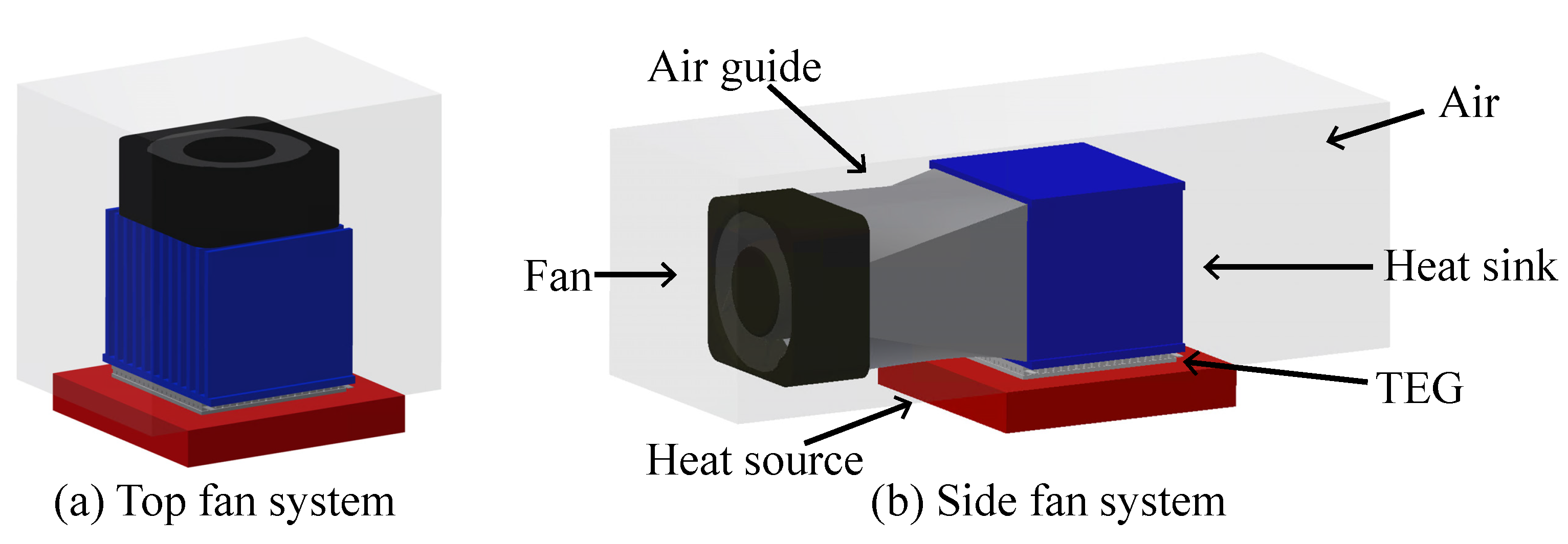
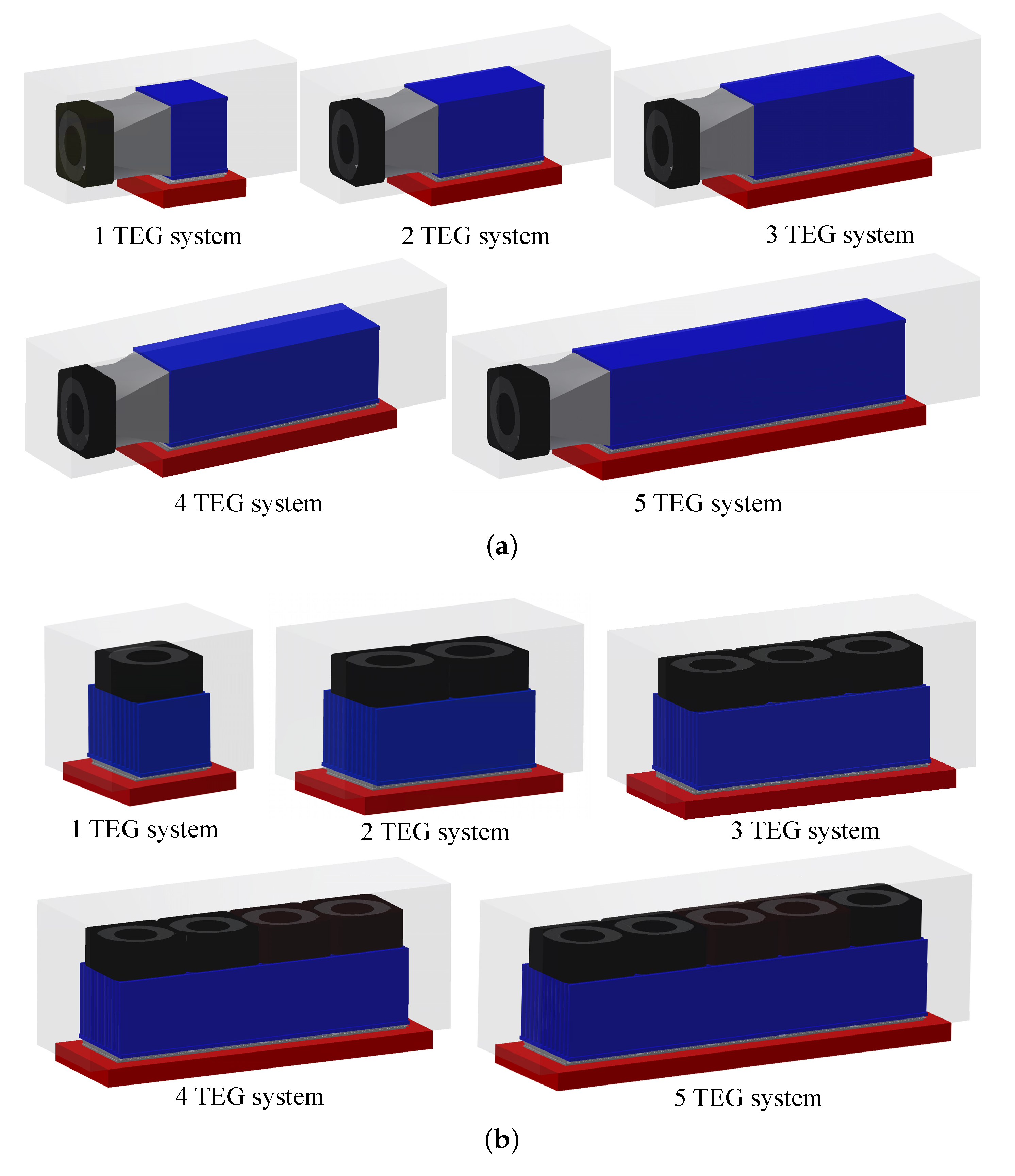
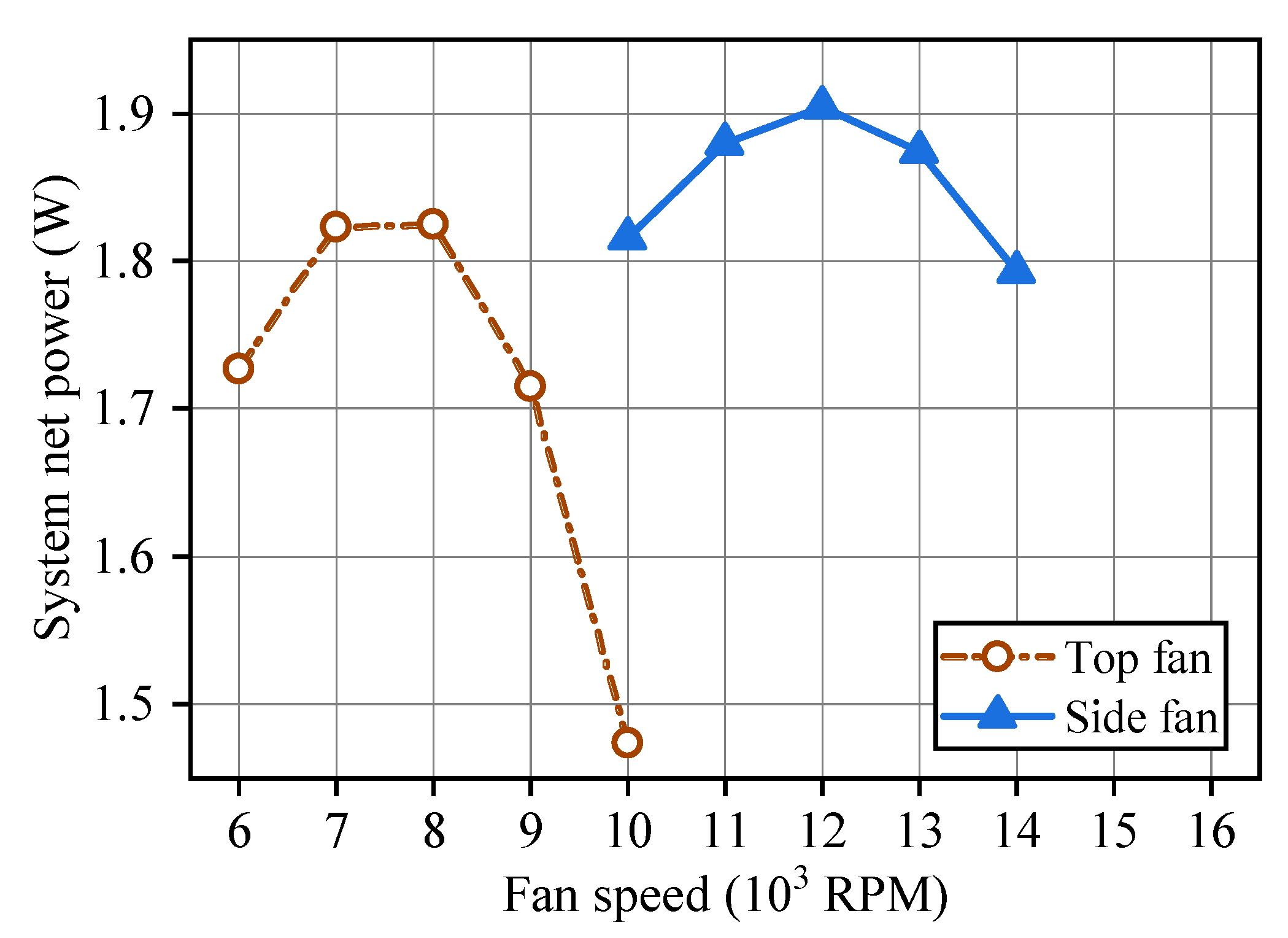
- We propose a side-mounted fan (SMF) system, which reuses an airflow for the most efficient system net power.
- We find the most rational number of TEG and most effective fan speed of the SMF system that generates the most efficient system net power by exploring design spaces.
- We present that the SMF-TEG system outperforms the TMF-TEG system on the system net power basis.
2. A Self-Cooling TEG System and Net Power Calculation
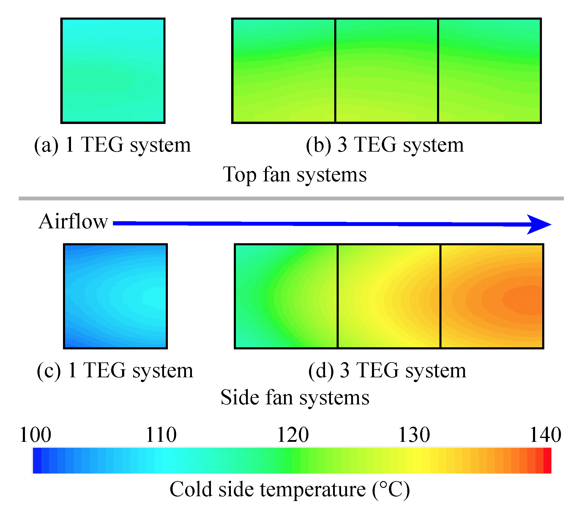
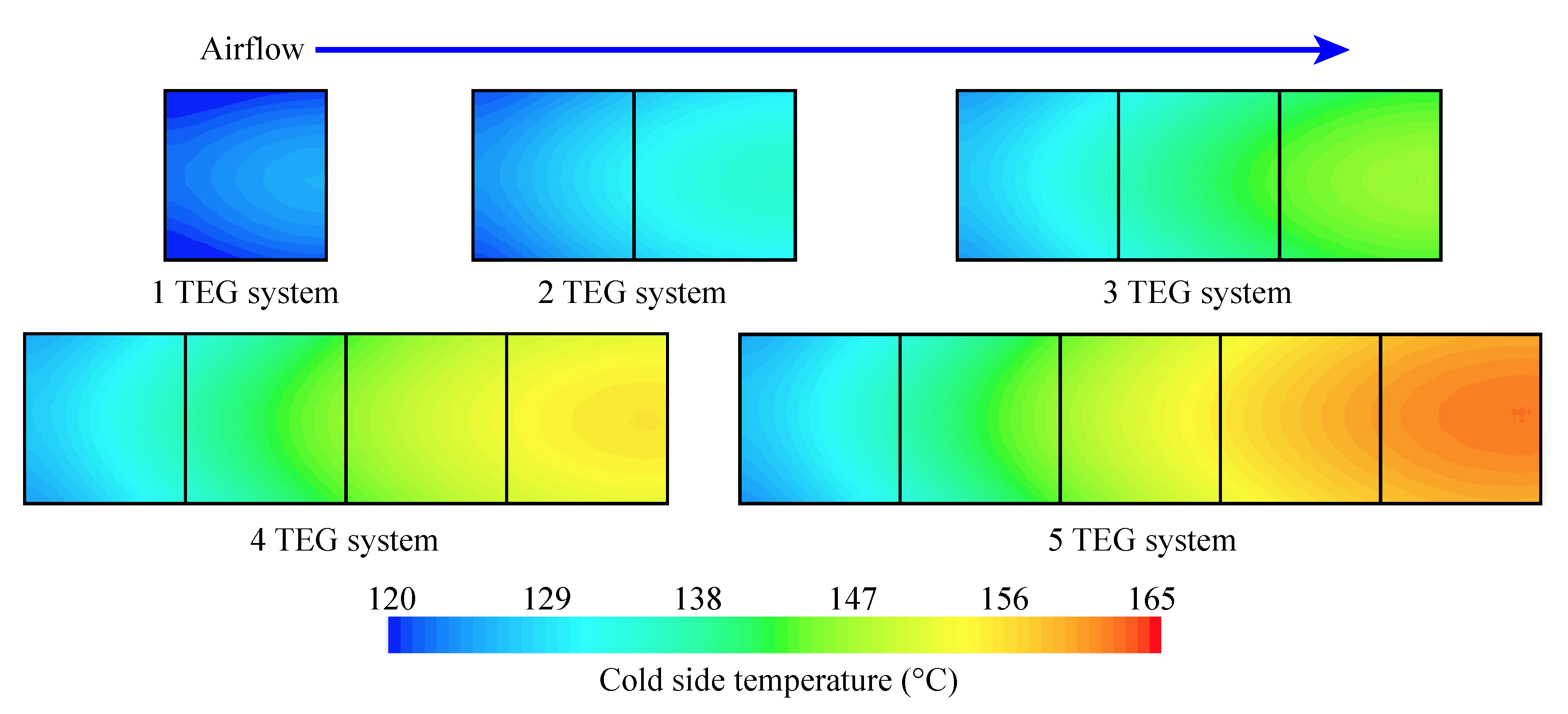
2.1. Airflow Reuse in a Forced Convection Cooling
2.2. Net Power of a Self-Cooling TEG System
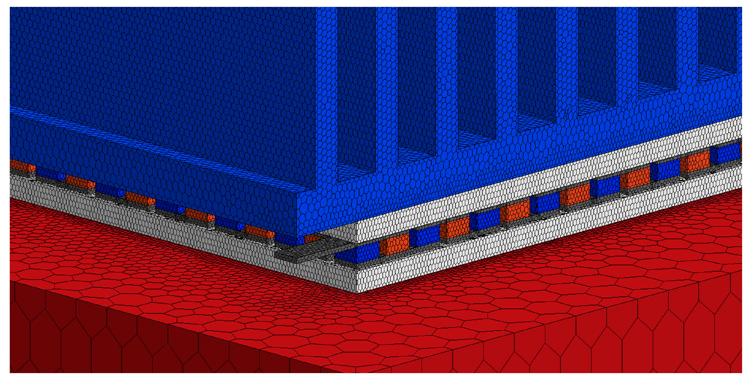
2.3. Computational Fluid Dynamics Simulation
3. Optimizing Net Power of a Self-Cooling TEG System
3.1. Power Models
3.2. Problem Statement
| Given: |
|
| Control knob: |
|
Goal:
|
4. Modeling of a Self-Cooling TEG
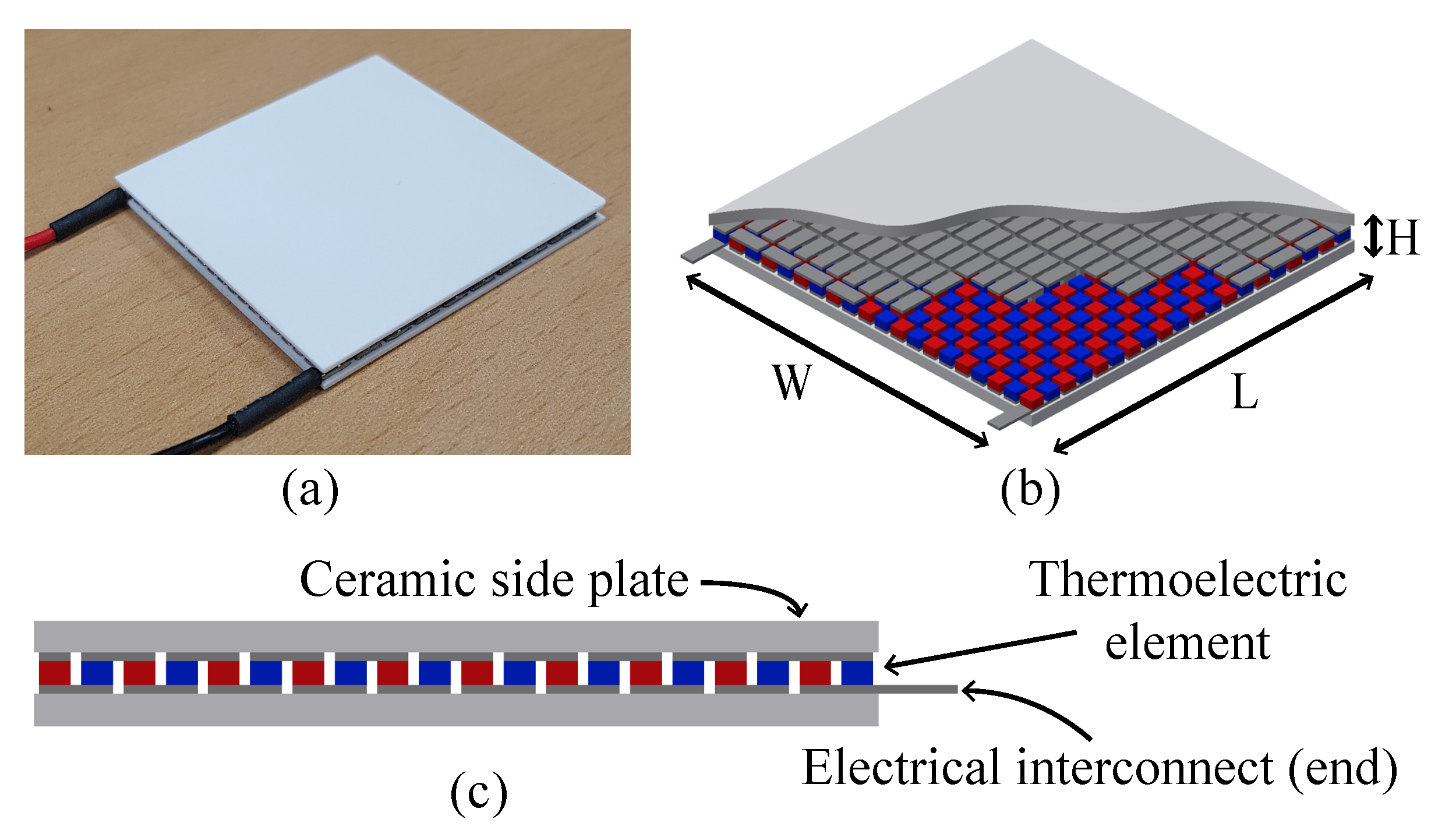
4.1. TEG Modeling
4.2. Cooling System Modeling
4.3. Assembled TEG System Modeling
5. Experiment
5.1. Experimental Setup
5.2. Experimental Result
6. Conclusions
Author Contributions
Funding
Conflicts of Interest
References
- Saha, B.; Perez-Taborda, J.A.; Bahk, J.H.; Koh, Y.R.; Shakouri, A.; Martin-Gonzalez, M.; Sands, T.D. Temperature-dependent thermal and thermoelectric properties of n-type and p-type Sc1-xMgxN. Phys. Rev. B 2018, 97, 085301. [Google Scholar] [CrossRef]
- Lee, J.; Kim, S.; Marconnet, A.; in’t Zandt, M.; Asheghi, M.; Wong, H.S.P.P.; Goodson, K.E. Thermoelectric characterization and power generation using a silicon-on-insulator substrate. J. Microelectromech. Syst. 2011, 21, 4–6. [Google Scholar] [CrossRef]
- O’Dwyer, C.; Chen, R.; He, J.H.; Lee, J.; Razeeb, K.M. Scientific and Technical Challenges in Thermal Transport and Thermoelectric Materials and Devices. ECS J. Solid State Sci. Technol. 2017, 6, N3058–N3064. [Google Scholar] [CrossRef]
- Shaikh, F.K.; Zeadally, S. Energy harvesting in wireless sensor networks: A comprehensive review. Renew. Sustain. Energy Rev. 2016, 55, 1041–1054. [Google Scholar] [CrossRef]
- Zhao, L.D.; Chang, C.; Tan, G.; Kanatzidis, M.G. SnSe: A remarkable new thermoelectric material. Energy Environ. Sci. 2016, 9, 3044–3060. [Google Scholar] [CrossRef]
- Sun, L.; Jiang, P.; Liu, H.; Fan, D.; Liang, J.; Wei, J.; Cheng, L.; Zhang, J.; Shi, R. Graphdiyne: A two-dimensional thermoelectric material with high figure of merit. Carbon 2015, 90, 255–259. [Google Scholar] [CrossRef]
- Kim, S.I.; Lee, K.H.; Mun, H.A.; Kim, H.S.; Hwang, S.W.; Roh, J.W.; Yang, D.J.; Shin, W.H.; Li, X.S.; Lee, Y.H.; et al. Dense dislocation arrays embedded in grain boundaries for high-performance bulk thermoelectrics. Science 2015, 348, 109–114. [Google Scholar] [CrossRef]
- Hu, L.; Zhu, T.; Liu, X.; Zhao, X. Point defect engineering of high-performance Bismuth-Telluride-based thermoelectric materials. Adv. Funct. Mater. 2014, 24, 5211–5218. [Google Scholar] [CrossRef]
- Hsiao, Y.; Chang, W.; Chen, S. A mathematic model of thermoelectric module with applications on waste heat recovery from automobile engine. Energy 2010, 35, 1447–1454. [Google Scholar] [CrossRef]
- He, W.; Wang, S.; Lu, C.; Zhang, X.; Li, Y. Influence of different cooling methods on thermoelectric performance of an engine exhaust gas waste heat recovery system. Appl. Energy 2016, 162, 1251–1258. [Google Scholar] [CrossRef]
- Orr, B.; Akbarzadeh, A.; Mochizuki, M.; Singh, R. A review of car waste heat recovery systems utilising thermoelectric generators and heat pipes. Appl. Therm. Eng. 2016, 101, 490–495. [Google Scholar] [CrossRef]
- Özdemir, A.E.; Köysal, Y.; Özbaş, E.; Atalay, T. The experimental design of solar heating thermoelectric generator with wind cooling chimney. Energy Convers. Manag. 2015, 98, 127–133. [Google Scholar] [CrossRef]
- Kim, S.J.; We, J.H.; Cho, B.J. A wearable thermoelectric generator fabricated on a glass fabric. Energy Environ. Sci. 2014, 7, 1959–1965. [Google Scholar] [CrossRef]
- Aranguren, P.; Astrain, D.; Rodríguez, A.; Martínez, A. Net thermoelectric power generation improvement through heat transfer optimization. Appl. Therm. Eng. 2017, 120, 496–505. [Google Scholar] [CrossRef]
- Eldesoukey, A.; Hassan, H. 3D model of thermoelectric generator (TEG) case study: Effect of flow regime on the TEG performance. Energy Convers. Manag. 2019, 180, 231–239. [Google Scholar] [CrossRef]
- He, W.; Wang, S.; Yue, L. High net power output analysis with changes in exhaust temperature in a thermoelectric generator system. Appl. Energy 2017, 196, 259–267. [Google Scholar] [CrossRef]
- Kim, J.; Baek, D.; Ding, C.; Lin, S.; Shin, D.; Lin, X.; Wang, Y.; Cho, Y.H.; Park, S.H.; Chang, N. Dynamic Reconfiguration of Thermoelectric Generators for Vehicle Radiators Energy Harvesting Under Location-Dependent Temperature Variations. IEEE Trans. Very Large Scale Integr. (VLSI) Syst. 2018, 26, 1241–1253. [Google Scholar] [CrossRef]
- Wang, C.C.; Hung, C.I.; Chen, W.H. Design of heat sink for improving the performance of thermoelectric generator using two-stage optimization. Energy 2012, 39, 236–245. [Google Scholar] [CrossRef]
- Gou, X.; Xiao, H.; Yang, S. Modeling, experimental study and optimization on low-temperature waste heat thermoelectric generator system. Appl. Energy 2010, 87, 3131–3136. [Google Scholar] [CrossRef]
- Rezania, A.; Rosendahl, L.; Andreasen, S.J. Experimental investigation of thermoelectric power generation versus coolant pumping power in a microchannel heat sink. Int. Commun. Heat Mass Transf. 2012, 39, 1054–1058. [Google Scholar] [CrossRef]
- Kobus, C.; Oshio, T. Development of a theoretical model for predicting the thermal performance characteristics of a vertical pin-fin array heat sink under combined forced and natural convection with impinging flow. Int. J. Heat Mass Transf. 2005, 48, 1053–1063. [Google Scholar] [CrossRef]
- Lv, S.; He, W.; Jiang, Q.; Hu, Z.; Liu, X.; Chen, H.; Liu, M. Study of different heat exchange technologies influence on the performance of thermoelectric generators. Energy Convers. Manag. 2018, 156, 167–177. [Google Scholar] [CrossRef]
- Martínez, A.; Astrain, D.; Rodríguez, A. Experimental and analytical study on thermoelectric self cooling of devices. Energy 2011, 36, 5250–5260. [Google Scholar] [CrossRef]
- Moran, M.J.; Shapiro, H.N.; Munson, B.R.; DeWitt, D.P. Introduction to Thermal Systems Engineering: Thermodynamics, Fluid Mechanics, and Heat Transfer; John Wiley & Sons, Inc.: Hoboken, NJ, USA, 2003; pp. 359–404. [Google Scholar]
- Kiflemariam, R.; Lin, C.X. Numerical simulation of integrated liquid cooling and thermoelectric generation for self-cooling of electronic devices. Int. J. Therm. Sci. 2015, 94, 193–203. [Google Scholar] [CrossRef]
- Lin, C.X.; Kiflemariam, R. Numerical Simulation and Validation of Thermoelectric Generator Based Self-Cooling System with Airflow. Energies 2019, 12, 4052. [Google Scholar] [CrossRef]
- Lakhkar, N.; Hossain, M.; Agonafer, D. CFD modeling of a thermoelectric device for electronics cooling applications. In Proceedings of the 2008 11th Intersociety Conference on Thermal and Thermomechanical Phenomena in Electronic Systems, Orlando, FL, USA, 28–31 May 2008; pp. 889–895. [Google Scholar]
- Fernández-Yañez, P.; Armas, O.; Capetillo, A.; Martínez-Martínez, S. Thermal analysis of a thermoelectric generator for light-duty diesel engines. Appl. Energy 2018, 226, 690–702. [Google Scholar] [CrossRef]
- Shen, R.; Gou, X.; Zhong, J. A Three-dimensional Dynamic Analysis CFD Tool for Thermoelectric Generators. Int. J. Thermophys. 2020, 41, 20. [Google Scholar] [CrossRef]
- Högblom, O.; Andersson, R. A simulation framework for prediction of thermoelectric generator system performance. Appl. Energy 2016, 180, 472–482. [Google Scholar] [CrossRef]
- Pfeiffelmann, B.; Benim, A.C.; Joos, F. Computational Investigation of Impingement Cooling of Thermoelectric Generators. Heat Transf. Eng. 2019, 1–14. [Google Scholar] [CrossRef]
- Wang, Y.; Wu, C.; Tang, Z.; Yang, X.; Deng, Y.; Su, C. Optimization of fin distribution to improve the temperature uniformity of a heat exchanger in a thermoelectric generator. J. Electron. Mater. 2015, 44, 1724–1732. [Google Scholar] [CrossRef]
- Chen, W.H.; Lin, Y.X.; Chiou, Y.B.; Lin, Y.L.; Wang, X.D. A computational fluid dynamics (CFD) approach of thermoelectric generator (TEG) for power generation. Appl. Therm. Eng. 2020, 173, 115203. [Google Scholar] [CrossRef]
- Khalil, H.; Hassan, H. 3D study of the impact of aspect ratio and tilt angle on the thermoelectric generator power for waste heat recovery from a chimney. J. Power Sources 2019, 418, 98–111. [Google Scholar] [CrossRef]
- Star-CCM+. SIEMENS Star-CCM+ Homepage. Available online: https://www.plm.automation.siemens.com/global/ko/products/simcenter/STAR-CCM.html (accessed on 17 June 2020).
- Chen, W.H.; Wu, P.H.; Wang, X.D.; Lin, Y.L. Power output and efficiency of a thermoelectric generator under temperature control. Energy Convers. Manag. 2016, 127, 404–415. [Google Scholar] [CrossRef]
- Yan, Y.; Malen, J.A. Periodic heating amplifies the efficiency of thermoelectric energy conversion. Energy Environ. Sci. 2013, 6, 1267–1273. [Google Scholar] [CrossRef]
- Kryotherm. Specification of Generating Thermoelectric Modules TGM-199-1.4-0.8. Available online: http://kryothermtec.com/assets/dir2attz/ru/TGM-199-1.4-0.8.pdf (accessed on 17 June 2020).
- Ferrotec USA. Thermoelectric Technical Reference. Available online: https://thermal.ferrotec.com/technology/thermoelectric-reference-guide/thermalRef02/ (accessed on 17 June 2020).
- Sanyo Denki. Cooling Fan San Ace. Available online: https://www.sanyodenki.com/archive/document/product/cooling/catalog_E_pdf/San_Ace_E.pdf (accessed on 17 June 2020).
- Sarvar, F.; Whalley, D.C.; Conway, P.P. Thermal interface materials-A review of the state of the art. In Proceedings of the 2006 1st Electronic Systemintegration Technology Conference, Dresden, Germany, 5–7 September 2006; Volume 2, pp. 1292–1302. [Google Scholar]
- Lemmon, E.W.; Jacobsen, R.T. Viscosity and thermal conductivity equations for nitrogen, oxygen, argon, and air. Int. J. Thermophys. 2004, 25, 21–69. [Google Scholar] [CrossRef]
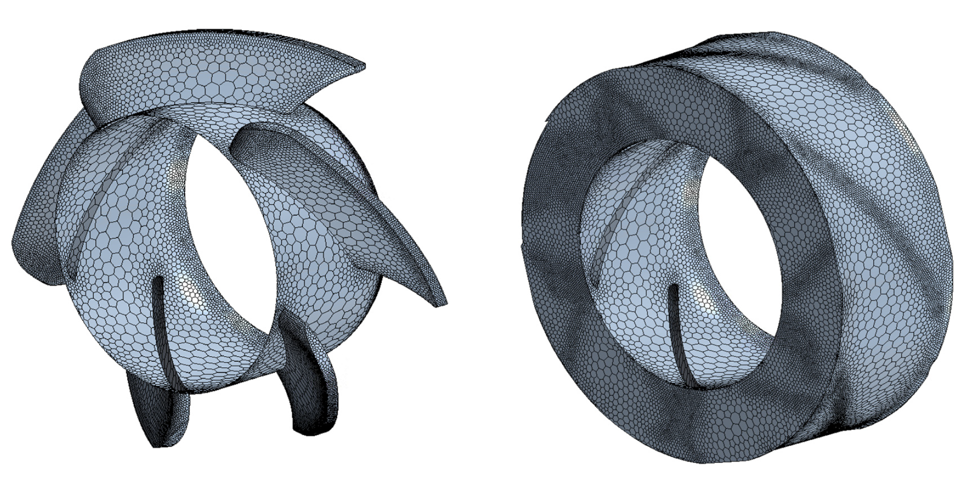
- Sosnowski, M.; Krzywanski, J.; Grabowska, K.; Gnatowska, R. Polyhedral meshing in numerical analysis of conjugate heat transfer. In EPJ Web of Conferences; EDP Sciences: Ulis, France, 2018; Volume 180, p. 02096. [Google Scholar]
- Symscape. Polyhedral, Tetrahedral, and Hexahedral Mesh Comparison. Available online: https://www.symscape.com/polyhedral-tetrahedral-hexahedral-mesh-comparison (accessed on 17 June 2020).
- Abdallah, A.; Krameldin, A. Optimum thermal design of steam pipelines and its impact on environment pollution. In Proceedings of the Conference on Heat Exchangers Boilers and Pressure Vessels, Cairo, Egypt, 3–5 October 1999; pp. 57–74. [Google Scholar]
- Ghalambaz, M.; Abdollahi, M.; Eslami, A.; Bahrami, A. A case study on failure of AISI 347H stabilized stainless steel pipe in a petrochemical plant. Case Stud. Eng. Fail. Anal. 2017, 9, 52–62. [Google Scholar] [CrossRef]


| Part | Dimension (mm) | Q’ty | ||
|---|---|---|---|---|
| L | W | H | ||
| TEG | 40 | 40 | 3.25 | - |
| Thermoelectric element | 1.5 | 1.5 | 0.75 | 400 |
| Electrical interconnect | 3.5 | 1.5 | 0.25 | 395 |
| Electrical interconnect end | 7.5 | 1.5 | 0.25 | 4 |
| Side plate | 40 | 40 | 1 | 2 |
| Heat sink | 48 | 40 | 42 | 1/TEG |
| Fin | 2 | 40 | 0.75 | 12 |
| Fin to fin | 3 | - | - | - |
| Top/bottom plate | 48 | 40 | 2 | 2 |
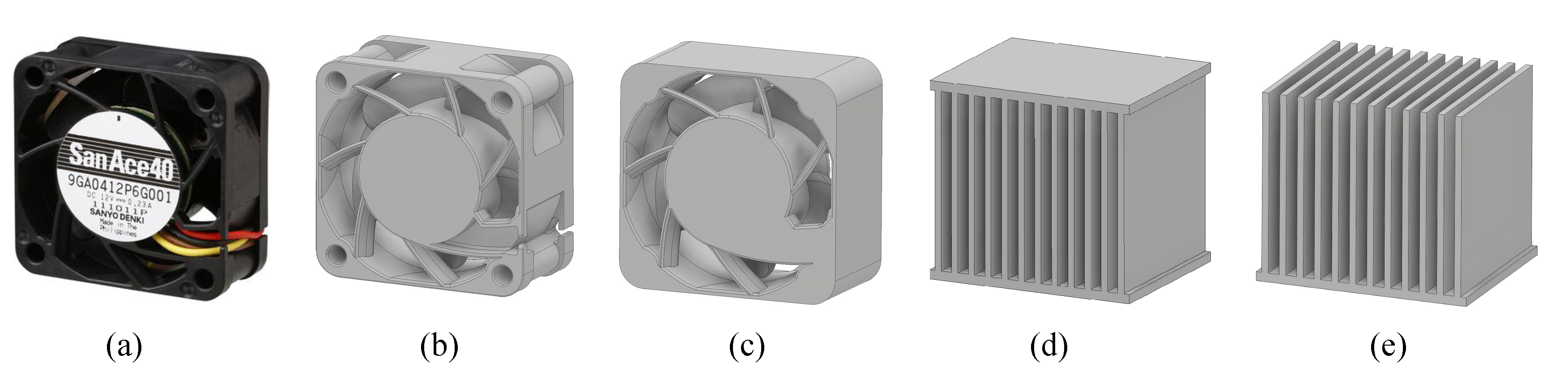
| Fan | 40 | 20 | 40 | 1 |
| Heat source | 60 | 20 + 40 × TEG# | 10 | 1 |
| Part | Material | Density | Thermal Cond. * | Specific Heat | Electrical Cond. * |
|---|---|---|---|---|---|
| (g/cm) | (W/mK) | (J/kgK) | (S/m) | ||
| TEG | |||||
| Thermoelectric element | Bismuth Telluride | 7.53 | 1.5 | 544.28 | - |
| Electrical interconnect | Copper | 8.96 | 386.0 | 385.19 | 5.96 |
| Side plate | Alumina Ceramic | 3.57 | 35.3 | 837.36 | - |
| Heat sink | Aluminum | 2.71 | 204.0 | 900.16 | - |
| Heat source | Aluminum | 2.71 | 204.0 | 900.16 | - |
| Number of | Number of | Most Effective | Fan Power | Most Efficient | Average Net Power |
|---|---|---|---|---|---|
| Fans | TEGs | Fan Speed | Consumption | System Net Power | per Unit TEG |
| (Q’ty) | (Q’ty) | (RPM) | (W) | (W) | (W/TEG) |
| TMF | |||||
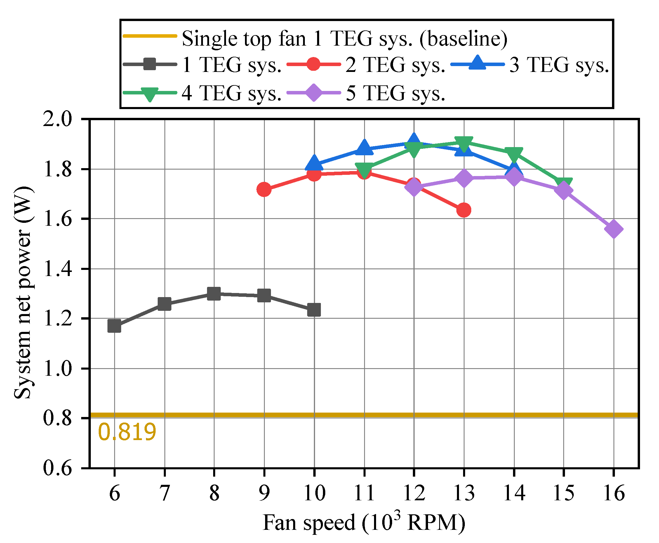
| 1 | 1 | 8000 | 0.345 | 0.819 | 0.819 |
| 2 | 2 | 8000 | 0.345 | 1.373 | 0.687 |
| 3 | 3 | 8000 | 0.345 | 1.825 | 0.608 |
| 4 | 4 | 7000 | 0.231 | 2.106 | 0.527 |
| 5 | 5 | 7000 | 0.231 | 2.109 | 0.422 |
| SMF | |||||
| 1 | 1 | 8000 | 0.345 | 1.299 | 1.299 |
| 1 | 2 | 11,000 | 0.897 | 1.785 | 0.893 |
| 1 | 3 | 12,000 | 1.164 | 1.906 | 0.635 |
| 1 | 4 | 13,000 | 1.48 | 1.907 | 0.477 |
| 1 | 5 | 14,000 | 1.849 | 1.768 | 0.354 |
© 2020 by the authors. Licensee MDPI, Basel, Switzerland. This article is an open access article distributed under the terms and conditions of the Creative Commons Attribution (CC BY) license (http://creativecommons.org/licenses/by/4.0/).
Share and Cite
Cho, Y.H.; Park, J.; Chang, N.; Kim, J. Comparison of Cooling Methods for a Thermoelectric Generator with Forced Convection. Energies 2020, 13, 3185. https://doi.org/10.3390/en13123185
Cho YH, Park J, Chang N, Kim J. Comparison of Cooling Methods for a Thermoelectric Generator with Forced Convection. Energies. 2020; 13(12):3185. https://doi.org/10.3390/en13123185
Chicago/Turabian StyleCho, Young Hoo, Jaehyun Park, Naehyuck Chang, and Jaemin Kim. 2020. "Comparison of Cooling Methods for a Thermoelectric Generator with Forced Convection" Energies 13, no. 12: 3185. https://doi.org/10.3390/en13123185
APA StyleCho, Y. H., Park, J., Chang, N., & Kim, J. (2020). Comparison of Cooling Methods for a Thermoelectric Generator with Forced Convection. Energies, 13(12), 3185. https://doi.org/10.3390/en13123185