1. Introduction
In power electronics systems, energy generation through renewable sources has gained greater importance in an endless number of industrial and social applications. From among all the renewable energies, the Photovoltaic systems (PV) have gained great popularity for power supply solutions due its suitability around the world. Additionally, according to [
1], energy harvested from PV systems are expected to be a great solution both for advanced economies and developing countries, since the energy demand is expected to grow 30% by 2040 (according to [
2]).
In addition, ref. [
2] points out that in order to move forward into a more sustainable future, a large expansion of renewable energy sources is required where Photovoltaic sources have a critical importance to achieve a better energetic transition from fossil fuels into renewable sources.
Therefore, as explained by the International Energy Agency in [
3], the PV energy provides the largest share of the expected global renewable capacity additions in most of the regions in the world. Thus, according to [
4] the solar energy leads the renewable power capacity expansion, expected to be 50% between 2019 and 2024. Ref. [
4] highlights that PV sources alone represent almost 60% of the expected total renewable energies growth, which can be translated into a 697 GW capacity growth for solar energy sources.
Hence, the increasing need for cleaner energy leads to arising research topics, regarding converters topologies, control algorithms, and techniques required to optimize the energy harvested from PV sources. Therefore, among the different emerging topics, computational intelligence algorithms have gained popularity as alternatives for parameters identification, the dynamic optimization of energy harvested, and the control of different photovoltaic systems (as explained in [
5]).
Consequently, the Maximum Power Point Tracking (MPPT) algorithms are widely studied, since they are responsible for tracking and acquiring the Maximum Power Point (MPP) of energy from the PV source. However, since the tracking of the MPP of a solar system is a dynamic optimization issue (as detailed later in this work), the problem requires a dynamic DC-optimizer (as explained in [
6]). Henceforth, the MPPT methods are usually employed through DC/DC converters, which allows one to modify the impedance at the output of the PV source, achieving a modulation of the energy acquired in terms of the voltage (
) and current (
) from the PV array, by using the converter as a variable impedance source at the array terminals. In other words, together the MPPT algorithms with the DC/DC converters are responsible for varying the impedance at the output of photovoltaic arrays, leading to a change in the current and voltage they supply, in order to achieve a dynamic optimization of the transferred energy, as explained in [
1].
On the one hand, the classic MPPT algorithms such as, the Perturb and Observe (P&O), Hill-Climbing (HC), or Incremental Conductance (IC) algorithms have been widely selected for many PV systems, regarding their mathematical simplicity and easy implementation capabilities ([
6]). Among them, the P&O has been the cornerstone for many solutions including IC and HC algorithms ([
1]), where in spite of correct tracking behavior with low calibration parameter dependence, this type of algorithms based on the classic P&O, carry with a high trade-off between the settling time and steady-state oscillations, due the magnitude of the perturbation that is continuously injected to the system, as explained in [
7].
Thus, on the other hand, nature-inspired solutions have been developed addressing the issue where the classical Particle Swarm Optimization (PSO) metaheuristic algorithm has served as the basis of a different approach, where in [
8] the PSO-based MPPT is presented as a solution with an improved settling time and with also lower steady-state oscillations, claiming the reduced steady-state oscillations as the main feature of the solution. Nevertheless, as studied by [
9], the performance of PSO-based techniques are highly susceptible and dependent to a correct and precise parameter calibration, dramatically changing the searching behavior of the algorithm depending on the selected population size or the algorithm coefficients initialization (as detailed in [
10]).
Henceforth, [
6] explains that the parameters to be tuned in the PSO-based MPPT, the premature convergence problems, and even the complexity of the algorithm, have constrained the application of the algorithm into real PV systems. The premature convergence of the algorithm has also been studied in [
11], where the results show how the classic PSO-based solution can fall into a local solution or induce greater oscillations due to the required re-initialization of the algorithm after irradiation changes, leading to conclude that the algorithm may not always ensure the expected tracking behavior (as validated in [
12]).
Accordingly, this work presents a novel alternative for MPPT, based on the Earthquake Optimization Algorithm (EA), which enables an optimization with an easy parameters calibration and an improved dynamic behavior. The proposed algorithm is based on the main EA explained in [
13], where the metaheuristic algorithm is characterized for using two different velocity equations, nature-inspired by the propagation equations of the P and S waves, which are part of physical earthquakes.
Therefore, the proposal seeks to take advantage of the performance of the fine search by the S-wave equation, in order to address the dynamic optimization issue of the MPPT for solar cells, allowing to transfer the fine search properties of the algorithm to this new solution, achieving a solution that improves energy harvesting. The searching behavior is always in the neighborhood of the best solution (as as explored in [
14]), traduced into a metaheuristic search with an intermediate stage that allows the algorithm to always return to the global best.
Nonetheless, ref. [
14] explores and compares many of the metaheuristic algorithms such as, PSO, Bat Algorithm (BA), Ant Colony (ACO), Grey Wolf Optimization (GWO), Genetic Algorithm, Cuckoo Search (CS), Artificial Bee Colony (ABC), and the EA among others. Thus, the comparison allows us to analyze how the fine search given by the S-wave velocity in the EA, makes it an efficient algorithm for the MPPT application, regarding the reduced searching space in terms of the control input that is given by the duty cycle.
Henceforth, in order to carry out the performance analysis of the proposed algorithm, a boost converter case study is proposed to verify the suitability of the proposed technique through Simscape Power Systems™ simulations in MATLAB/Simulink
®, regarding the dynamic model fidelity capabilities of the software. Thereby, ref. [
15] validates that simulations through Simscape™ can be used as valid testbeds for the performance of a plant. Accordingly, ref. [
16] corroborates the capabilities of the Simscape Power Systems™ time-based simulations, for the study of the dynamic performance in control systems for power electronics. Thus, based on the study presented in [
17], the efficiency of the power electronics system can be analyzed through the Simscape simulations.
Moreover, a boost converter topology was selected for the performed tests, since it has been widely used for PV applications as explored in [
18,
19], being that (according to [
20]) it has a high voltage gain ratio, with simple implementation capabilities due the few elements required for its construction.
Nevertheless, as explained in [
21], the presence of the non-minimum phase propitiated by the Right Half Plane Zero (RHPZ) in its transfer function, makes it a more challenging topology compared to buck converters or other topologies without RHPZ for MPPTs algorithms, since the algorithms could fall into erroneous behaviors due to the characteristic behavior of non-minimum phase elements, in this case since the voltage against each duty cycle change will first go in the opposite direction to the point at which it will stabilize (as explored by the resulsts presented in [
22]), causing in turn erroneous readings that may cause confusion in control systems (as further explored in [
23]).
Results show that the proposed technique can be easily suitable between different power applications, and as expected, conclude in a faster response compared to the P&O and the PSO-based MPPT algorithms. The quantification of the results showed that after the performed scenarios the EA-based MPPT consistently managed to harvest the most energy (measured through the power through the simulation time), with a lower standard deviation regarding the voltage at MPP, having been reduced between 12% and 36% of the energy wasted in the 10 s of simulations compared to both solutions.
The standard deviation in this work is used as a statistical tool in order to validate the behavior of the algorithms regarding steady-state oscillations, since by definition the standard deviation is the measurement of the amount of variation in a set of values. On the other hand, the statistical mean is estimated in order to evaluate the mean convergence error of the algorithms, which in addition to the standard deviation allows one to evaluate the behavior of the algorithms compared to the maximum achievable power.
This work presents in
Section 2 the basic concepts of the mathematical model of the PV modules, later
Section 3 details the dynamic optimization issue addressed through the MPPT algorithms. Additionally,
Section 3 presents in
Section 3.1 and
Section 3.2, the searching behavior of the P&O and PSO-based MPPTs as a preamble to the main proposal of this work presented in
Section 4. On the other hand,
Section 5 explains the proposed case study scenarios, of which the results are broken down in
Section 6. Finally,
Section 7 shows the final conclusions of this work.
2. Modeling of a PV Module
In terms of energy harvesting sources, PV modules are responsible for converting sunlight to electrical energy, which according to [
24], requires one to consider weather input data. Therefore, from the temperature and solar irradiation, current, voltage, and power harvested from the PV arrays can be estimated.
According to [
1], the best way to analyze the dynamic behavior of a PV generator in simulated environments is adopting an equivalent model that enables the analysis of the key elements of the system, and therefore allowing to obtain its most relevant equations.
Hence, to understand how the input parameters affects the energy supplied by the PV modules, the single diode model with ohmic losses is chosen to study the dynamic optimization issue to be solved through the MPPT algorithms. The basic scheme of the electric diagram of the model is shown in
Figure 1.
The model shown in
Figure 1 corresponds to the single-diode model, which according to [
25], may correctly model the performance for most type of solar cells, considering the performance at low irradiance for thin films-based solar cells as its main drawback. Nevertheless, the model is enough for this study purposes, knowing that the dynamic parameterization of the selected cells for the case study designs are the requirements needed to be fulfilled. In other words, the selected model is used to obtain the I-V (Current-Voltage) characteristics of the solar cells.
Then, from
Figure 1, the output current from the solar cell (
I) can be defined through Kirchhoff’s current law, obtaining the expression shown by Equation (
1).
where
is the generated current from the PV cell,
the current through the diode, and
the current through the parallel resistor. Additionally, as described in [
24],
can be rewritten in terms of the Irradiance (
G) and Temperature inputs (
T) giving rise to Equation (
2).
where
G stands for solar irradiation,
T is the cell temperature,
the coefficient of temperature of short circuit current, and the terms with subscript
, represent the same variable but under
Standard Test Conditions. On the other hand, Equation (
3) represents the behavior of
from Equation (
1), in terms of
G and
T.
where
is the reverse saturation current from the diode,
V the voltage supplied by the module, and
the series resistance of the module shown in
Figure 1. Additionally,
a is taken as a change of variable (also known as “the modified ideality factor” [
24]), where the term is defined as:
where,
is known as the thermal voltage, according to [
1,
25,
26],
A is the ideality factor of the cell,
the number series connected cells in the module,
k the Boltzmann constant
J/K,
q the electron charge factor (constant
C), and
the temperature in the cell. Additionally for Equation (
3),
can be defined as [
24]:
where
is the short circuit current,
the voltage in open circuit, and
the material’s band gap energy. Finally from Equation (
1),
is the current leak through the parallel resistor and therefore according to [
24]
can be taken as:
Henceforth, as explained in [
24,
25], the Voltage against Current characteristic profile can be obtained by sweeping voltages in order to estimate the current in every point, meanwhile the Voltage against Power profile can be obtained by the existing relation
.
Then,
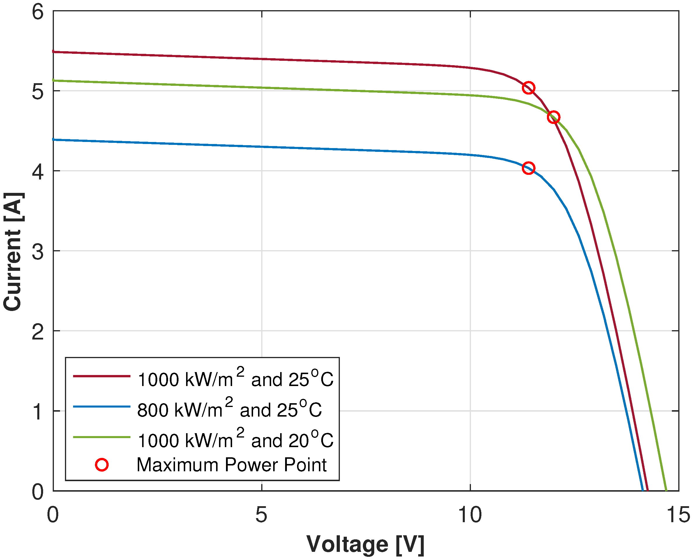
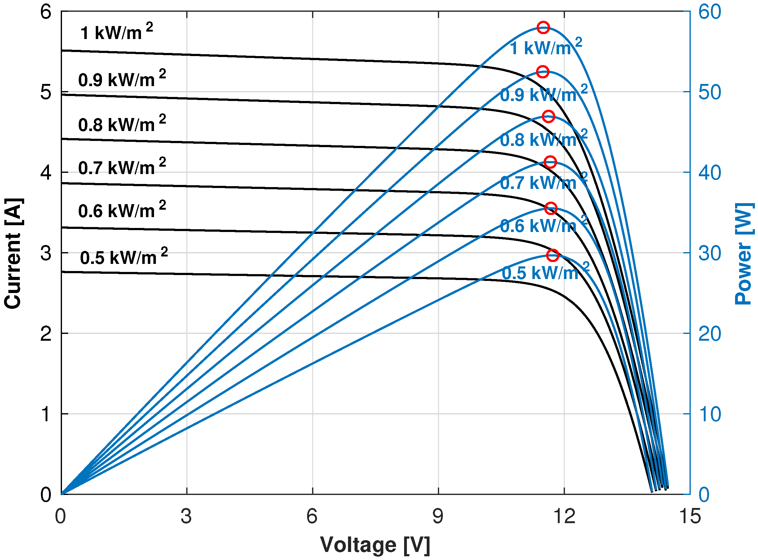
Figure 2 shows the I-V characteristics of the solar modules selected for the low power simulations in this work, where the MPP is highlighted in the curves, exemplifying the variations of the MPP regarding the irradiance or temperature changes.
Meanwhile, the curves analyzed in
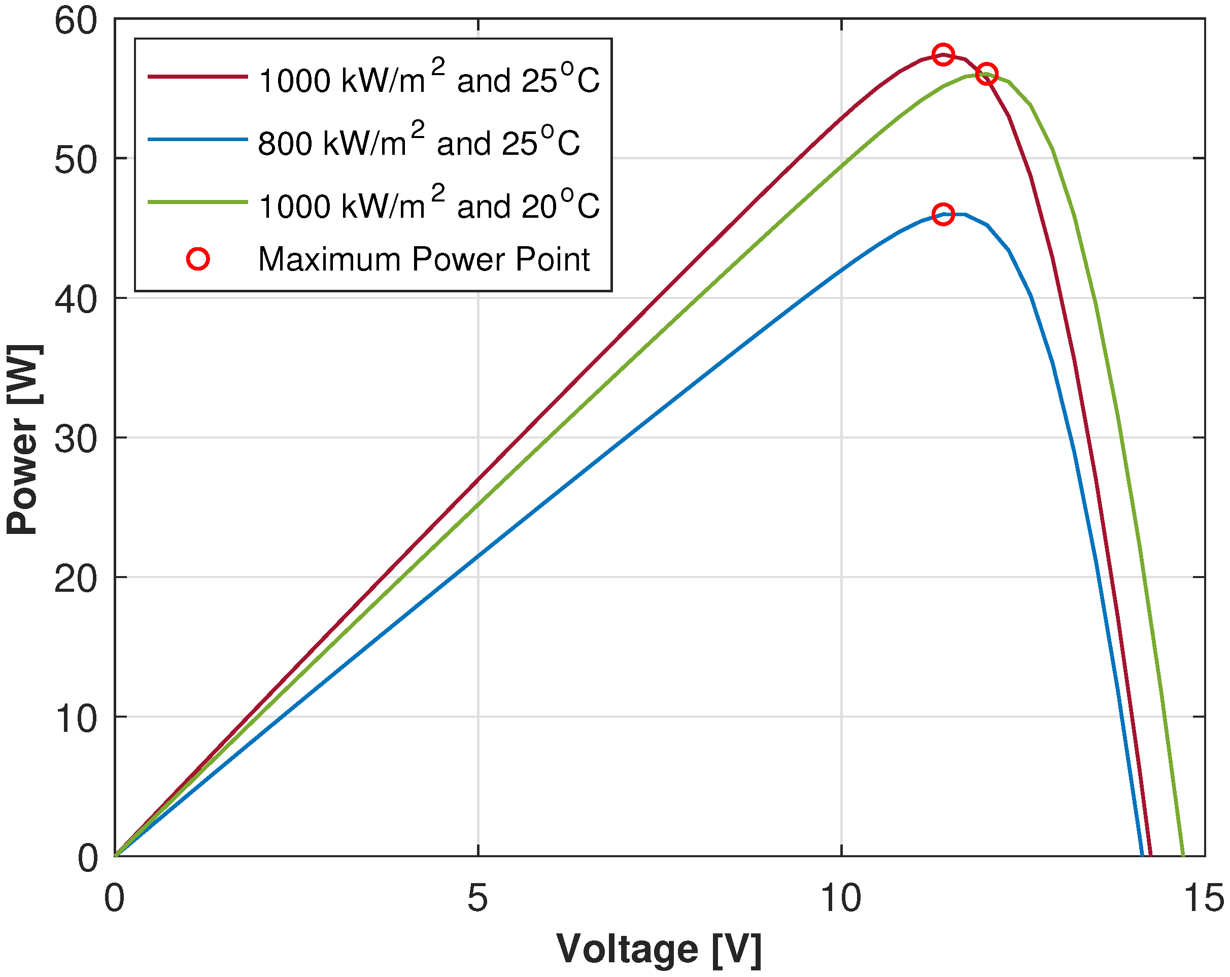
Figure 2 can be processed in order to obtain the power against voltage features, a profile that is shown in
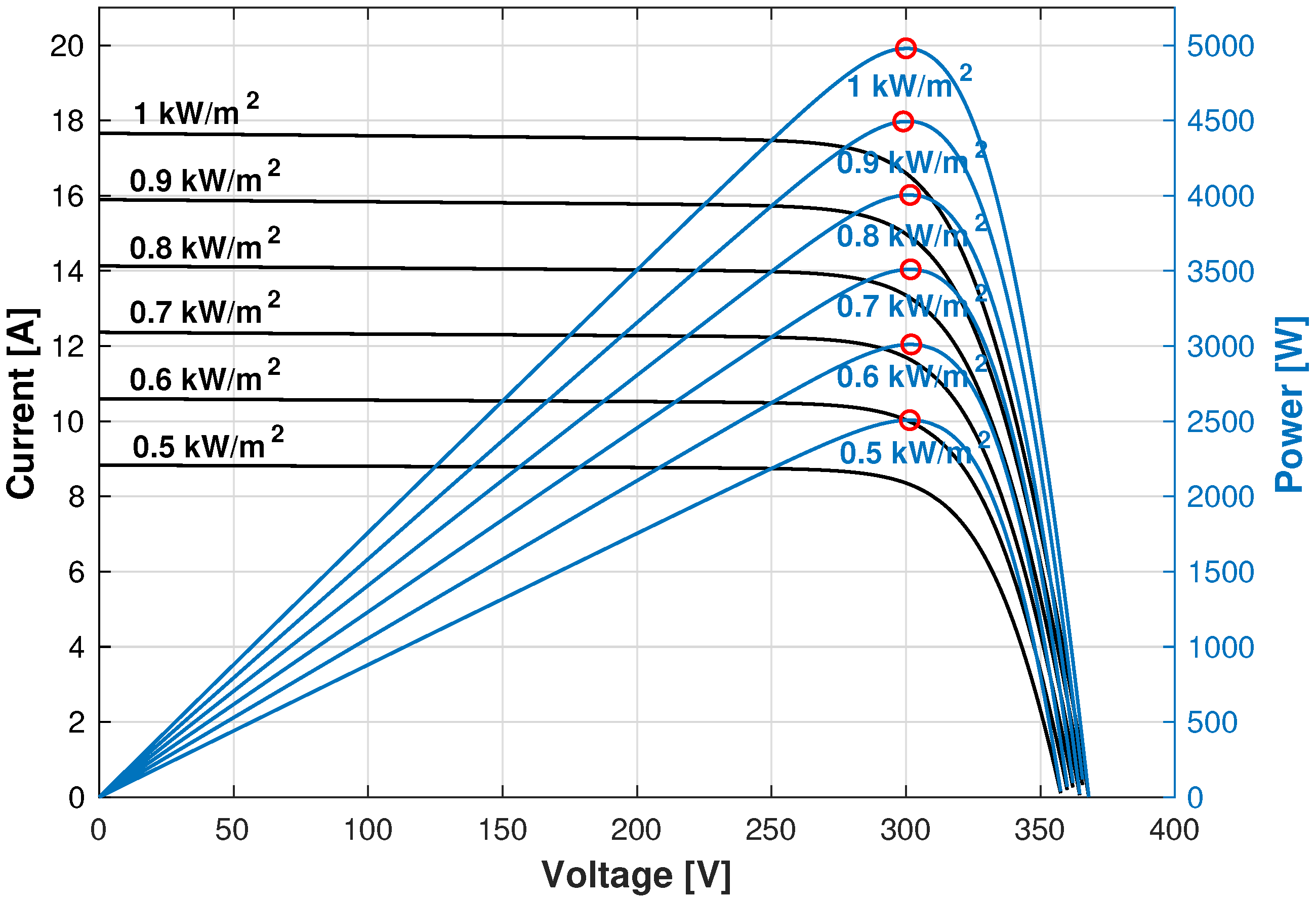
Figure 3 where it can be seen how the maximum achievable power may be affected by the input changes regarding to the unpredictable weather changes. The above leads to the dynamic optimization issue to be solved by the MPPT algorithms.
3. Maximum Power Point Tracking
Assuming the Maximum achievable power as a dynamic point with unpredictable variations due to the Temperature and Irradiation changes, the issue has to be dealt by a dynamic optimizator. As explained in [
1], DC/DC converters can achieve a dynamic optimization of the impedance of the circuit, in order to control the transferred power through the regulation of the duty cycle
d of the converter. Therefore, the control parameter of the system is taken as
d of the main switch or switches of the converter (depending on the selected topology for the application).
In [
23], the conversion ratio of different converter topologies regarding the duty cycle are explained, and in [
1] it is explained how the conversion ratio can be explained as the equivalent resistance and voltage at the PV source terminals.
Therefore, to determine the path the duty cycle has go through, in order to ensure a Maximum Power Point operation of the PV source regardless the irradiance and temperature conditions, Maximum Power Point Tracking (MPPT) controllers are implemented.
Figure 4 shows how the maximum power point moves depending on different variations, exemplifying the behavior first in STC (red profiles), then with a 20% of irradiance reduction (blue curves), next to a 20% of temperature reduction (green profiles), and finally with a 20% or reduction in both irradiation and temperature input conditions (purple profiles). In the case of all curves from
Figure 4, the profiles with continuous lines are current curves, which are plotted in respect to the the left axis. Meanwhile the curves with segmented lines are plotted in respect to the right axis, representing the power behavior resulted from the Current against Voltage curves.
According to [
9], MPPT controllers base their operation on data acquisition regarding the instantaneous current and voltage values sensed by the PV generator terminals. Moreover, by the knowledge of the obtained power related to the actual duty cycle in the converter, the MPPT takes the acquired data as comparison points in order to trace a route to be followed by the new duty cycles, depending on the tracking algorithm implemented.
3.1. Perturb and Observe
As explained earlier, as the duty cycle is the control parameter to be moduled in order to achieve a correct power tracking, the dynamic optimization issue can be dealed by different MPPT solutions, where one of the most implemented algorithms is the classic Perturb and Observe (P&O) algorithm that, as studied in [
1,
9,
27], has been widely implemented and served for inspiration of many other algorithms due to its simplicity and effectiveness relation.
Basically, the P&O algorithm bases its operation on the injection of small perturbations into the system, in other words small variations of duty cycle, whose effects are measured in order to evaluate if the response is better or worse than the obtained from the previous duty cycle, therefore the result traces the road to be followed in the direction of the MPP.
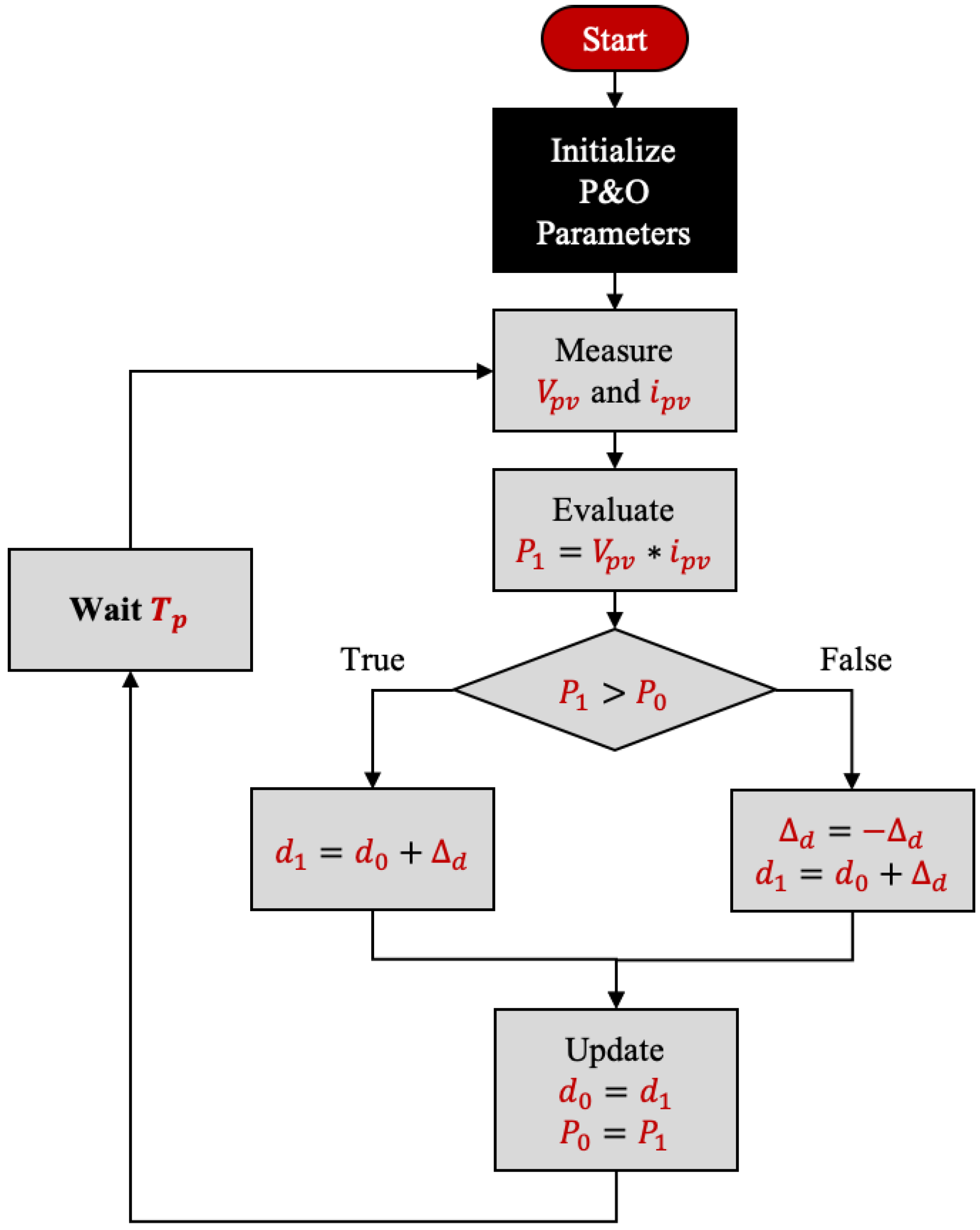
Hence, to better explain the operation of the algorithm,
Figure 5 shows a basic flow chart of the P&O MPPT. The algorithm starts with the system in a determined operating point, the initial point is usually set with the previous knowledge of the design parameters of the system, which means that it can be initialized with the estimated duty cycle operating in STC.
The actual state of the systems is perturbed every period of time, by changing the duty cycle d in order to apply a voltage variation to the PV source terminals. After each applied disturbance, the algorithm seeks to compare the resultant power supplied by the PV array (). The change in the actual measured Power (), is compared to its previous power value (), leading to the direction of the next perturbation to be applied.
It is important to highlight that, in order to achieve a good measure of the power after the perturbation, must be selected as a waiting time so that the system can stabilize since the presence of non-minimum phases in some converter topologies or even the same response speed of the system can be impediments to properly measure whether the response was better or earlier after the duty applied changes.
3.2. Particle Swarm Optimization Based Algorithm
As explained in [
1], the P&O MPPT algorithm has served as inspiration for plenty of MPPT applications, within which, applications based on metaheuristic algorithms are found. Thus, a MPPT method based on the Particle Swarm Optimization (PSO) algorithm has been proposed by [
8], where the online optimization is performed by perturbations applied through the classical PSO’s velocity and position equations.
Firstly, the seminal version of the metaheuristic algorithm was introduced in [
28], where the original PSO operates via a set of particles moving towards the personal and global best solutions from a set of particles, iterating until the expected error or maximum iterations conditions are fulfilled. Nevertheless, the most implemented version of the PSO algorithm contemplates an inertial weight coefficient, as described in [
29,
30]. Therefore, equations used to update each particle’s velocity (
v) and position (
x) are given by:
where
and
are the acceleration constants and
w is the inertia weight that allows the balance of the global and local search capabilities, the coefficient should be normally calibrated between 0 and 1 as recommended in [
31], in order to guarantee convergence. On the other hand,
and
in Equation (
7), are random variables calculated between 0 and 1 for every particle on every iteration [
28].
In the case of the portability of the algorithm for its application as a MPPT tool, the positions given by
x are taken as the duty cycles to be uploaded, meanwhile the velocities (
v) are the variations to be uploaded into the
j position, so that the behavior inspired from the P&O algorithm is achieved. Therefore,
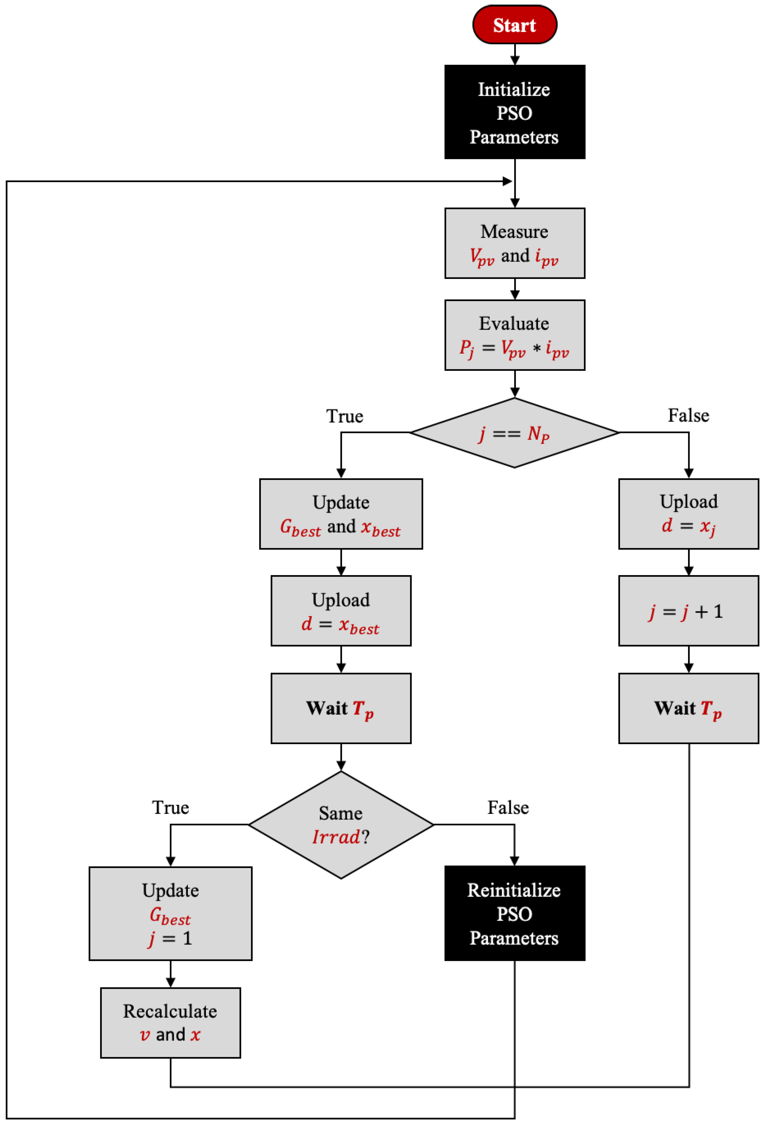
Figure 6 shows the flowchart of the PSO-based MPPT algorithm, where
and
are the best global and personal solutions of the particles. Additionally, it is important to highlight that MPPT approaches based on metaheuristic methods, retain most of the virtues and hence the defects of the original metaheuristic optimization algorithms, as analyzed in [
8,
9].
Thereafter,
Figure 6 shows the general structure of the PSO adapted as a MPPT algorithm, where it can be analyzed that after the initialization of the PSO parameters, the algorithm begins with the measurement of the voltage and the current from the PV source, then the process has two threads depending on whether the algorithm is loading the particles to the duty cycle or not. When the counter of particles
j differs from the number of particles
, the positions of each particle is charged one by one to the duty cycle, just as in the P&O algorithm, perturbing the system and observing the results.
On the other hand, when
, the method takes the natural behavior of the typical PSO, by obtaining and updating the MPP value and the best duty cycle positions. Additionally as explained in [
9], a scanning process has to be made in order to detect irradiation changes, a task that can be achieved by comparing the previous MPP value against the new one, determining if the system still achieves the saved maximum power transfer with the duty cycle saved as the current best position. If a change in solar irradiation is detected, then the PSO parameters must be reinitialized to ensure that the algorithm does not stagnate in a local solution.
4. Proposed MPPT Based on the Eartquake Algorithm
The Earthquake Algorithm (EA) is the first geo-inspired metaheuristic algorithm (as explained in [
14]), based on the behavior of the
P and
S waves existing in earthquakes. The first sketch of the algorithm appeared in [
32], while the first complete version of the algorithm was formally introduced in [
33], with its extended version in [
13].
Therefore, as explained in [
13], the algorithm takes advantage of the characteristics between wave velocities, where the
P-wave is faster on the earth material compressibility, meanwhile the
S-wave is slower and directly depends on rocks elasticity causing epicenters to move up and down, constantly perpendicular to the wave direction. For that reason (also from [
13]), Equations (
9) and (
10), are the given mathematical expressions for the
P and
S waves velocities respectively.
where
and
are the waves velocities,
and
the Lamé parameters, and
the density of material. As explained in [
13,
33], the optimal relation for the Lamé parameters was found to be 1.5, consequently:
Besides, for the implementation of the classic version of the algorithm, the density of the solids (
) is used as a random value, selected from a range between 2200 and 3300 kg/m
3, also according to [
13]. Nevertheless, in order to determine whether to use
or
, for the algorithm it is a key element to define an operation range for the
S-wave, which will be referred in [
13] as the
S-range or
Sr.
However, the main structure of the adaptation of the geo-inspired algorithm for the MPPT implementation is shown in
Figure 7. Where, as explained in [
13], the EA within its
S-range (Sr) has a fine searching behavior, characterized for “orbiting” the global best value. Thus, extrapolating that feature for the dynamic optimization of the MPP tracker, the solution requires to contemplate that the epicenters should be “orbiting” around the MPP, to ensure a correct optimizing behavior.
Under those circumstances, a searching flag () is implemented to insert the best duty cycle within the searching positions, achieving the expected route-ways during the searching stage, and also extending the time that the system will remain in the considered MPP.
Unlike the PSO approach, the original EA has two velocity equations, which is why for this first adaptation of the algorithm, it is important to highlight that the equation is taken for this first approach of the algorithm adaptation.
Moreover, in order to clarify the similarities and differences between the original EA and the EA-based MPPT, the main features of this algorithm are enlisted below. The EA-based MPPT algorithm proposed in this paper takes advantage of the finer search of the original EA given by Equation (
10), which allows dealing with the dynamic optimization, where the inputs of the EA-MPPT system are
and
leading to the fine optimization of the duty cycle (control parameter) for the power converter.
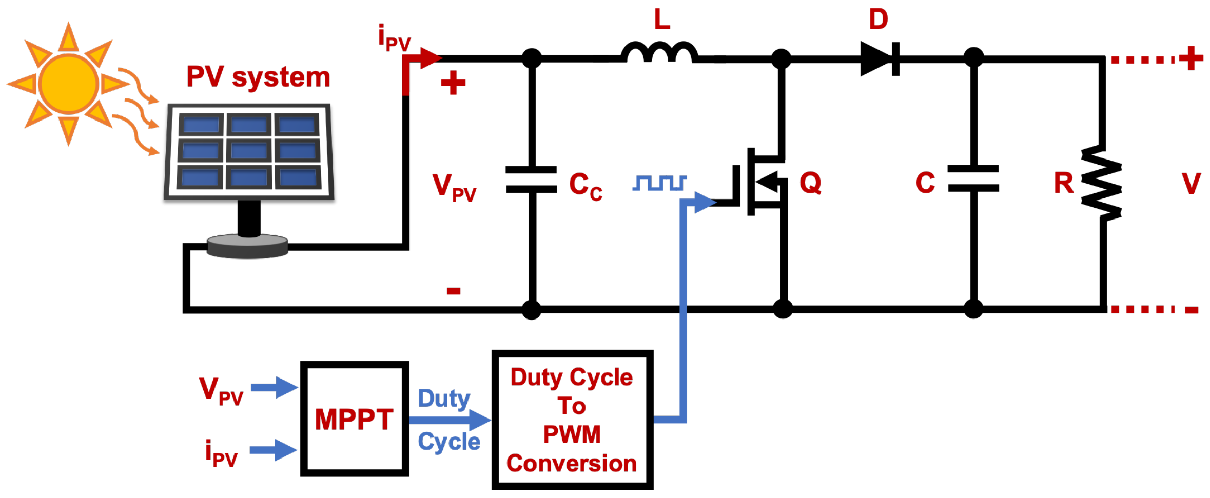
Figure 8 highlights the main parameters of the system, where the inputs and outputs of the MPPT are summarized through the MPPT block.
Nevertheless, the main differences between this proposal and the original EA are based on the suitability requirements of PV systems, since this algorithm returns to the global best duty cycle after evaluating an epicenter and allows verifying how the irradiation features are changing before uploading the next epicenter, which in addition performs a faster reaction against irradiation changes compared to other algorithms, since algorithms like PSO-based MPPT monitors the irradiation changes after all sets of particles are induced into the system (as explored through the differences between
Figure 6 and
Figure 7).
6. Results
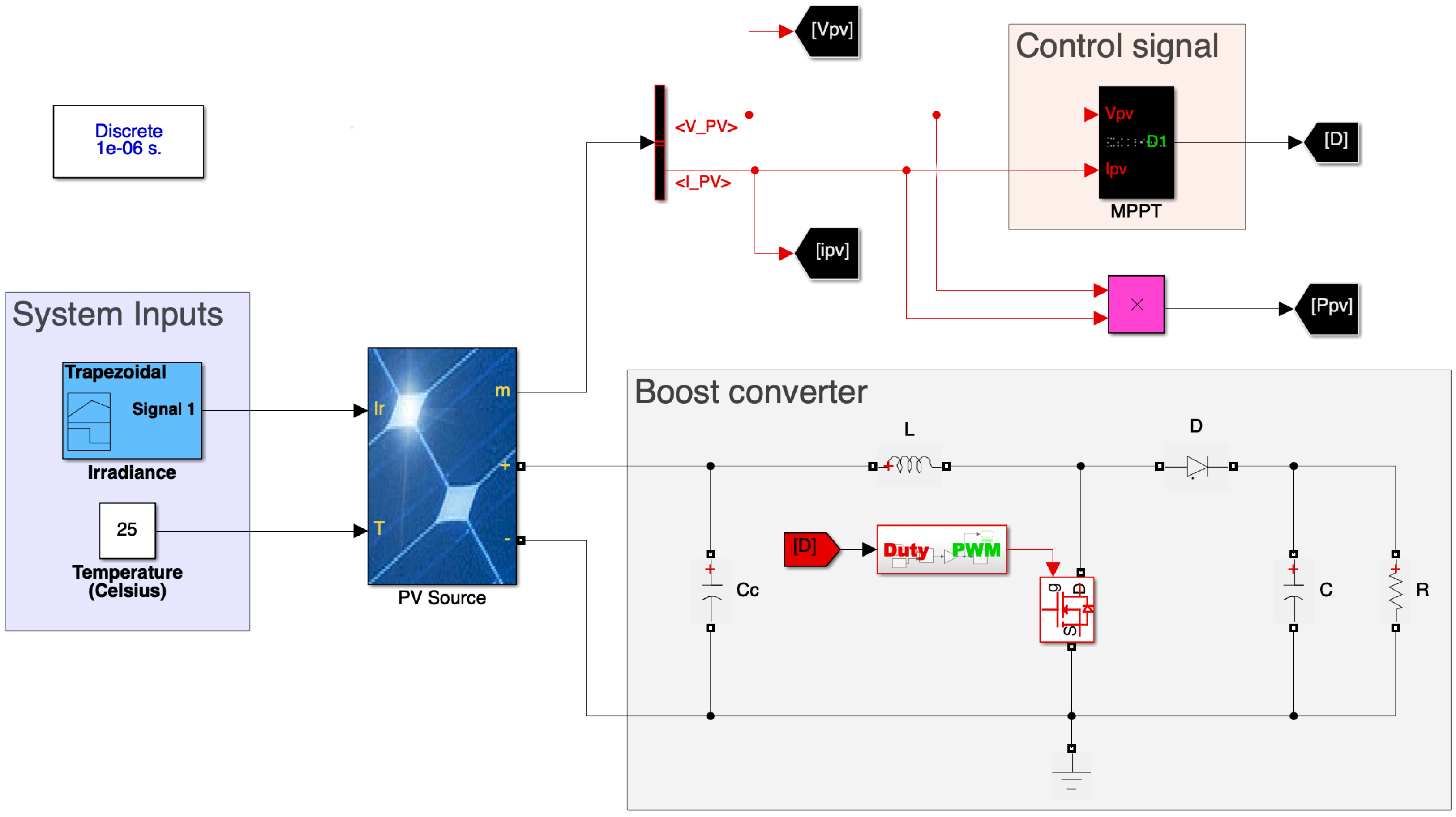
The simulations were performed using the model summarized by
Figure 8, where its implementation in the Simulink environment is traduced into the model illustrated in
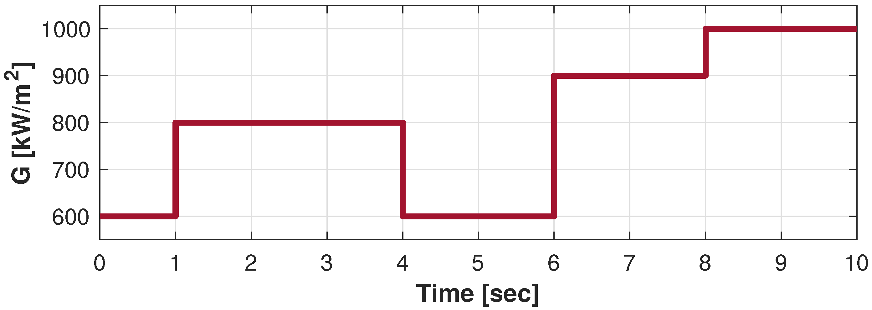
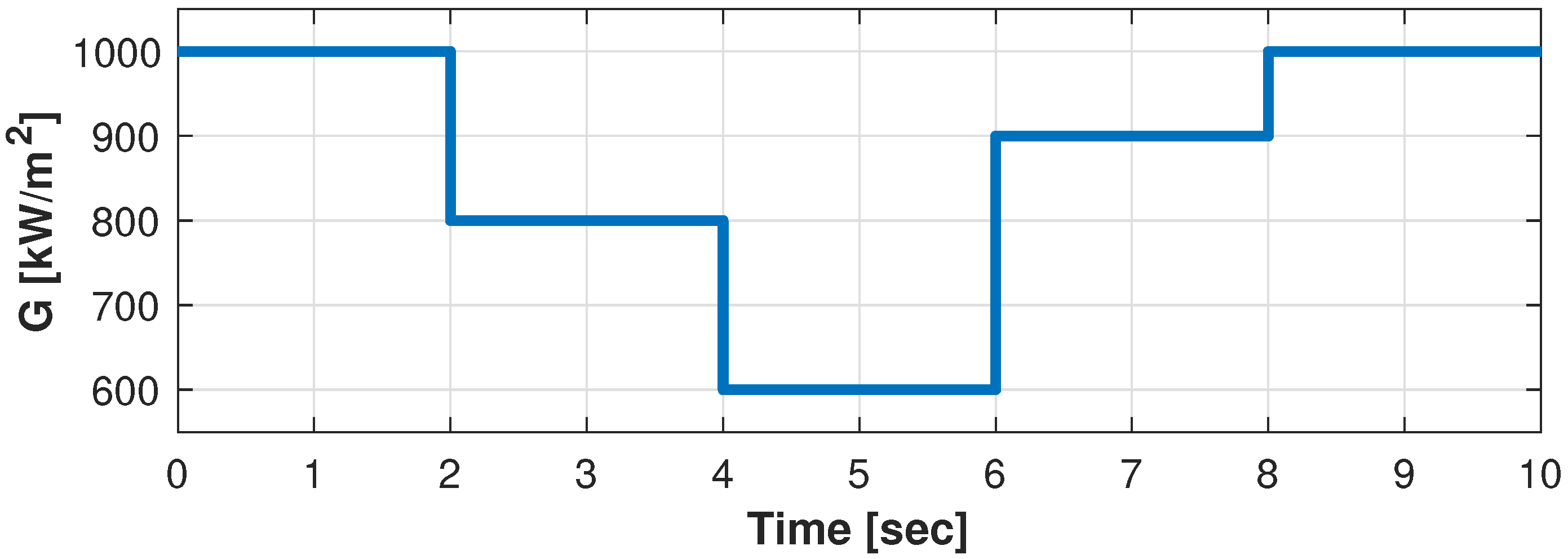
Figure 15 and the set of inputs are taken as the variable irradiation profiles (described in
Figure 11 and
Figure 12) and the Temperature. On the other hand, the PV source block is taken as the different PV systems described in
Table 3 and
Table 4.
Moreover, the Boost converter is also highlighted in
Figure 15, where its parameters change as shown in
Table 1 and
Table 2, regarding the power simulation to be evaluated. Nevertheless, as highlighted in the Boost converter set, the duty cycle is the control parameter obtained from the MPPT algorithms. Finally, it is important to highlight that for the implementation of the PSO- and EA-based algorithms, the obtained output is directly the duty cycle of the system, contrary to what happens with the P&O implementation, where the duty cycle has to be inverted through the conversion ratio of the DC/DC converter, whereas in this case the duty cycle is taken as
.
Additionally, the MPPT methods were compared through simulations run in MATLAB Simulink, using Simscape Power Systems™ components. In regards to the dynamic model fidelity capabilities of the software, the tests were performed using the parameters shown in
Table 5 where the solver
ode4, stands for Ordinary Differential Equations solver 4. Finally, all results in this paper were achieved using a 0.1 s sample time for all algorithms, meanwhile the EA-based MPPT was implemented using 2 epicenters, and the PSO-based MPPT used a population of 4 particles (which is a particles population also validated in [
9]).
6.1. Low Power Simulation Results
Therefore, from the first simulation, it is worth remembering that it was carried out by taking the PV array with the characteristics summarized by
Table 3, together with the converter whose parameters are described in
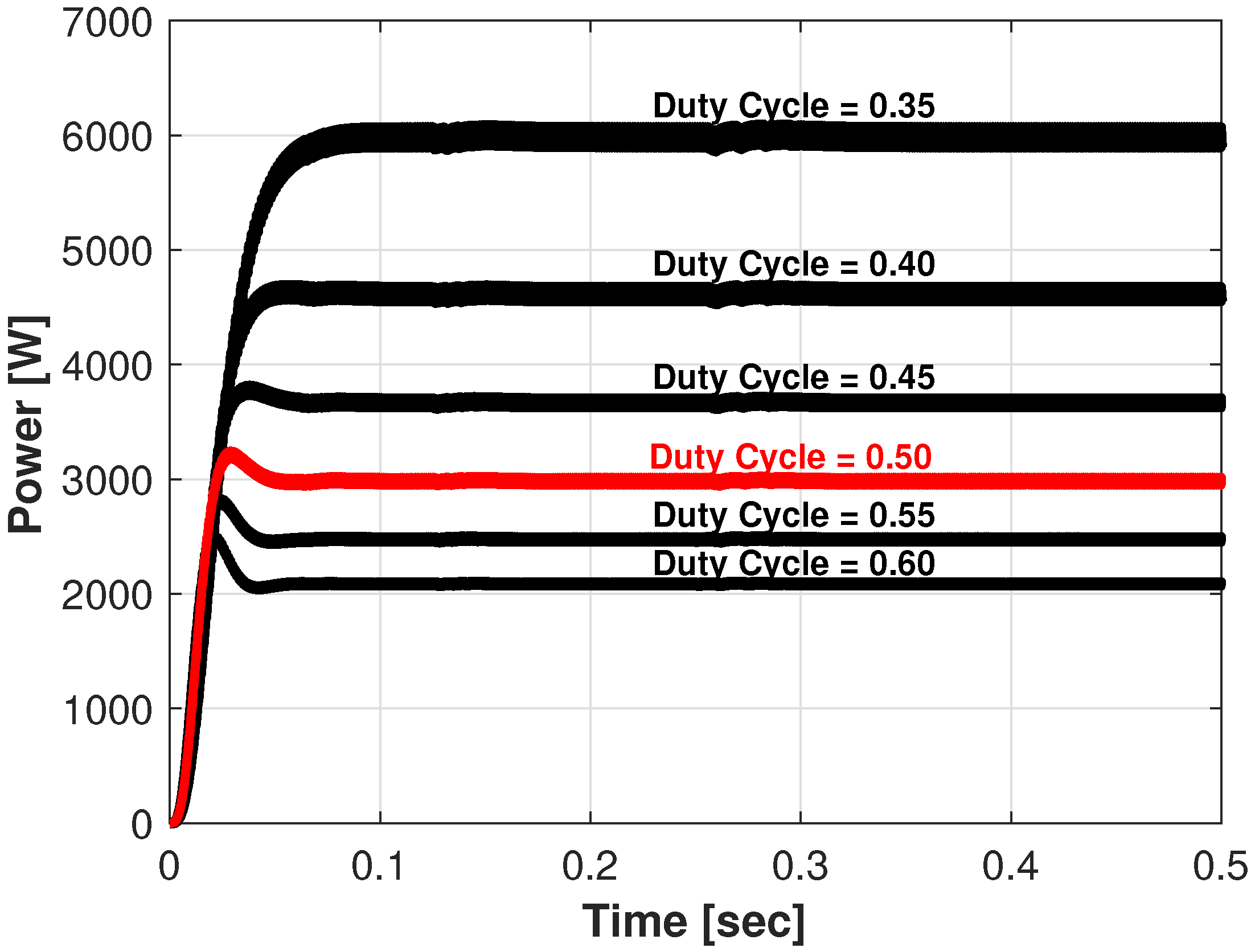
Table 1. Therefore, taking as the expected power behavior the simulated profiles from
Figure 13, the tests were performed through the dynamic irradiation input from
Figure 11. Thus,
Figure 16 shows the Power through time results comparison between the algorithms.
In all the presented curves in this section, the Red profiles were obtained through the EA, the Blue profiles were obtained by the PSO-based algorithm, the Green ones were obtained from the P&O results, and finally the segmented and dotted line is the reference estimation obtained through the model discussed in
Section 2.
Hence, the P&O algorithm showed its reliability against dynamic changes, always achieving a near MPP approximation, but generally with a slower response regarding the other two algorithms. In spite of the PSO-based algorithm achieving a highly effective response reaching the MPP, there was a highly compromised relation between the performance of the algorithm and the population size (as also validated in [
9]).
As shown during the second and third irradiation step, the PSO achieved to find the MPP by gradually reducing the oscillations around it, nevertheless it generally compromised the efficiency when fast dynamic conditions were introduced, shown in the next irradiation changes. Now, regarding the EA-based MPPT, it achieved the fastest recovery in the last three irradiation changes and even an almost immediate solution in the last step, achieving it with lower computational cost regarding the lower epicenters population (compared to the particles population of the PSO).
However,
Figure 17 and
Figure 18 shows the breakdown of the power obtained, in terms of the voltage and current respectively from the PV source. Where theoretically, as explained in [
1], the input voltage in the converter should be nearly constant at a MPP operation mode, the current profile reflects the dynamic behavior of the current.
That is the behavior that is shown by the results analyzed through
Figure 17 and
Figure 18, where on the one hand, the
profile showed the dynamic correction of the algorithms when the irradiation changes occurred, achieving a nearly constant value (11.5 V as estimated in
Table 3). Nevertheless, the steady voltage state was recovered faster in almost every irradiation change using the EA-based MPPT.
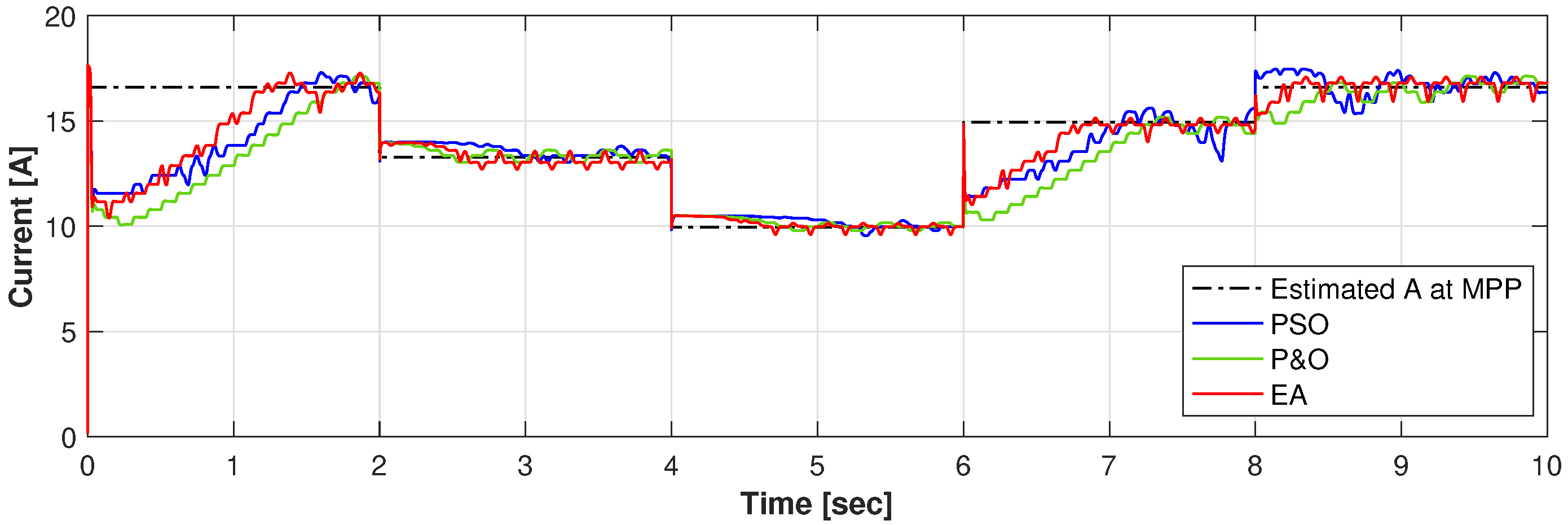
On the other hand, the
curve from
Figure 18 shows the dynamic behavior of the current through time, where it can be seen how the induced perturbations from the PSO search had a greater effect in the current than on the voltage of the source, and hence responsible for the power oscillations in the
performance. Therefore, regarding the current profile, the P&O and the EA solutions provided less
ripple, but the EA proved to be a more effective solution due its searching time and the achieved steady-state oscillations.
6.2. High Power Simulation Results
Now, speaking of the simulation with greater power, it is important to remember that it was performed by taking the PV array with the characteristics summarized by
Table 4, in addition to the converter parameters described in
Table 2. In this case, the expected power behavior is the one described in
Figure 14. Thus, the irradiation input is taken from
Figure 12. Consequently,
Figure 19 shows the Power through Time comparison between the algorithms, regarding high power simulation.
Thereby, after both simulations, the consistency of the results is demonstrated where in the case of the
profiles from
Figure 16 and
Figure 19, the EA-based MPPT showed to be in almost all cases the fastest response. The PSO showed great reliability in always finding the MPP, showing the greatest characteristic of the algorithm, when in all cases it gradually reduced the oscillations around the MPP. Nevertheless, the convergence was not always quickly achieved, showing again a compromised efficiency when fast dynamic conditions were introduced (as also validated in results presented in [
9]).
Furthermore,
Figure 20 and
Figure 21 are the Voltage and Current (respectively) components of the Power curve from
Figure 19. Comparing the voltage results from
Figure 17 and
Figure 20, it can be inferred that in both cases the faster and even smoother response after a parametric deviation, from solar irradiation, was achieved from the EA-MPPT algorithm. Moreover, the
maintained an average steady-state against small changes but a quick correction response against greater ones.
Nevertheless, the oscillations induced by the searching behavior of the algorithms could be better analyzed from the , where it can be seen that the searching behavior of the PSO algorithm was the most aggressive, regarding its searching performance when fast dynamic changes in the irradiation were induced. Nonetheless, the oscillations were dampened through time, being the main advantage of that approach, in other words, slow changes where the temperature and irradiance inputs remained almost constant, the PSO tended to collect more and more energy due to its convergence capacity.
6.3. Results Quantification
Finally, in order to quantify the obtained results,
Table 6 summarizes the numerical results from the algorithms where the results are presented for each algorithm in the presented scenarios, reviewing the energy harvested through the simulation time and therefore its efficiency, estimated by contrasting the calculation of the integral of the power curve against the integral of the estimated total power (as detailed in [
9]). In all cases from
Table 6, the highlighted in red numbers are the best results obtained from the simulations.
For the low power simulation, the estimation of the maximum achievable energy harvested led to be 468.5 W for the 10 s simulations, which can be broken down into 40.38 A as the maximum current to be obtained from the case study. Meanwhile, the achievable power that could be obtained from the higher power simulation resulted in 43.000 kW for the 10 s simulations, which can be traduced as 142.7600 A of achievable current through time.
Firstly, the indicators regarding the power harvested (Energy Harvested, MPPT Efficiency, and Total Wasted Power), showed a clear trend in the performance of algorithms, where the most efficient algorithm was in both scenarios the EA-based MPPT, consistently achieving the greater power through time, the greatest efficiency, and therefore the lowest wasted energy.
However, regarding the voltage and current components of the energy harvested, the average at MPP showed different results regarding both study cases where the best result regarding the stability reflected by the standard deviation of the voltage signal was achieved in both cases by the EA-MPPT but the result that converged better to the estimated voltage at MPP was obtained by the PSO-MPPT in the lower power simulation (11.5 V at MPP) and by the EA-MPPT in the greater power case study (300 V at MPP).
On the other hand, the results from the current through time profiles showed that the error through time had its better behavior through the EA-based algorithm in the lower power simulation and through the PSO approach in the higher power case. Nevertheless, it is important to highlight the fact that the best tracking behavior was achieved by both metaheuristic-based approaches where the dynamic optimization issue was dealt better in summary by the proposed optimization algorithm.
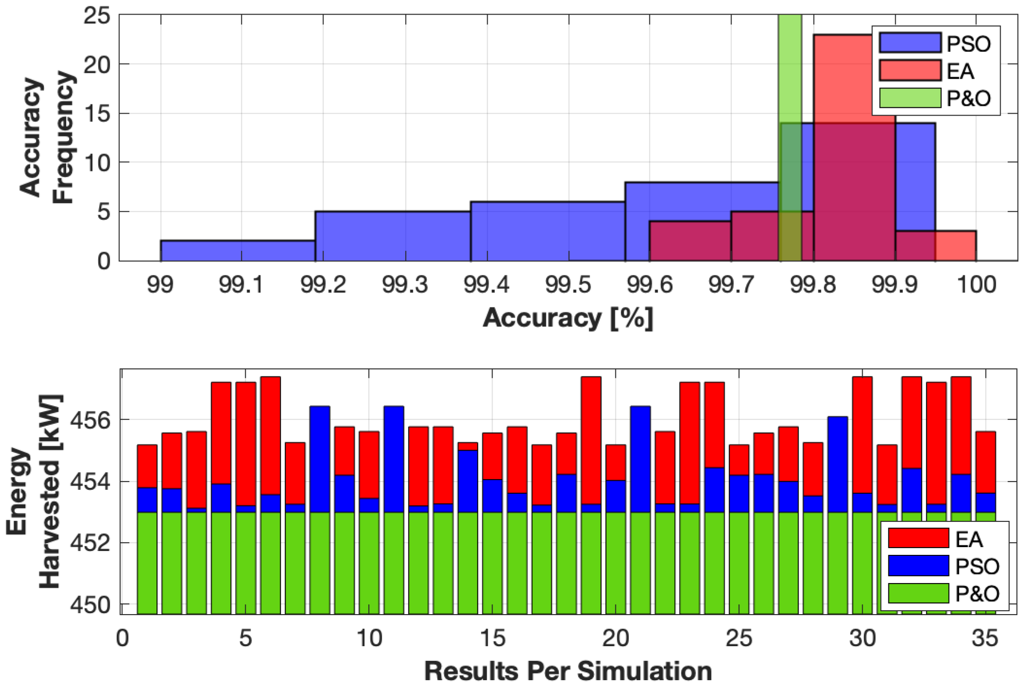
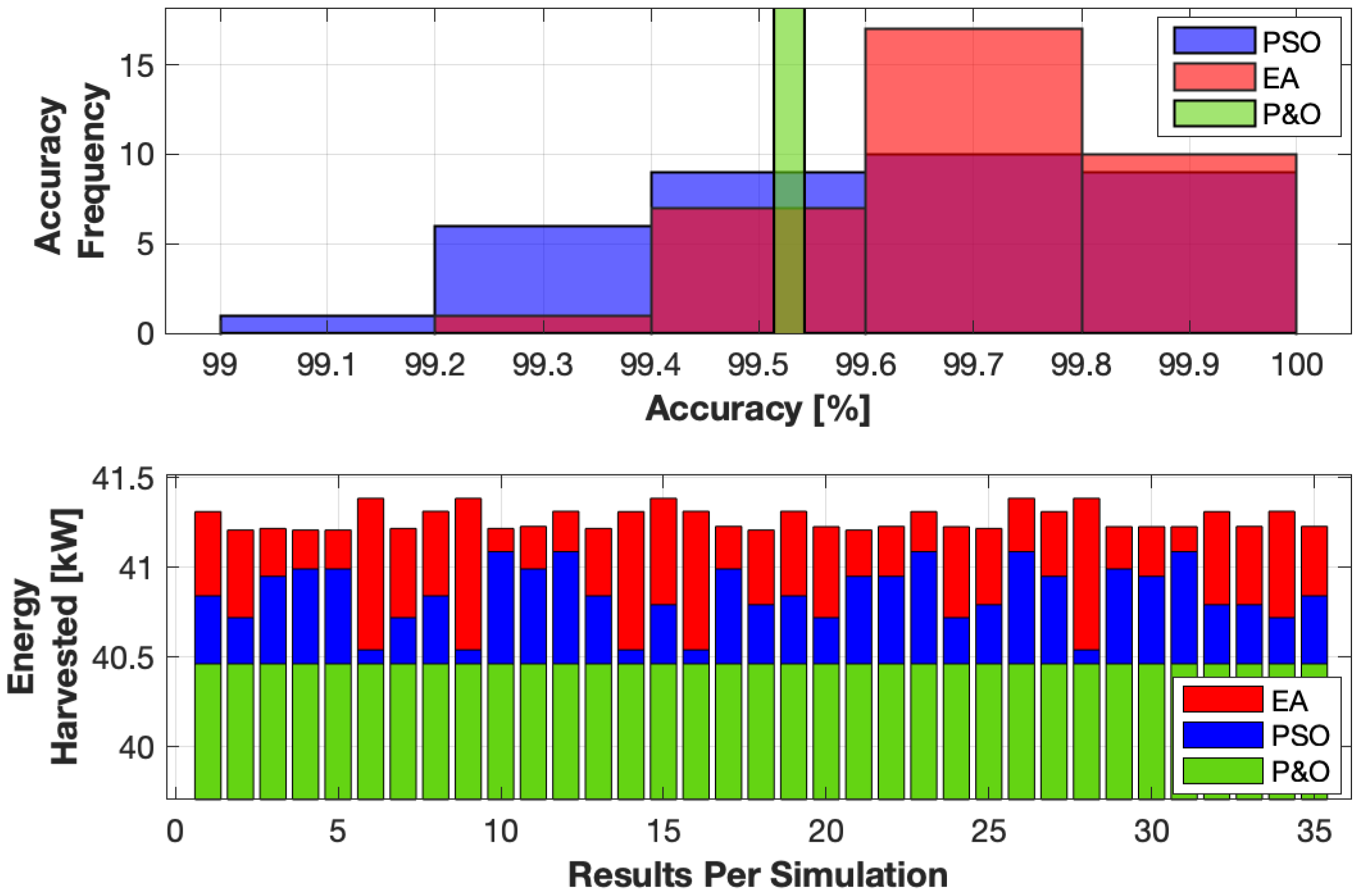
Nevertheless, since the PSO- and EA-based algorithms are stochastic optimization methods, the experiments where repeated 35 times in order to acquire a statistical analysis of the energy harvested through time. Therefore, the accuracy histograms from
Figure 22 (low power simulations) and
Figure 23 (high power simulations), where the accuracy frequency represents the times that the algorithms achieved the presented accuracy percentage from the tracked MPPs.
It is important to highlight that since the P&O algorithm is not stochastic, the accuracy and the energy harvested of the algorithm did not change through the iterations, thus the green bars from the accuracy histograms were only indicating the accuracy of the algorithm obtained in all the performed simulations (99.7735% and 99.5297% in the low and high power simulations respectively). Meanwhile, in the case of the P&O algorithm, the energy harvested through all the performed tests was fixed in 452.9863 W for the low power and 40.462 kW for high power cases.
Henceforth, the histograms allow one to validate that statistically, the metaheuristic optimizations trend to perform a more accurate tracking behavior regarding the MPP changed through time yet, the EA-based MPPT showed standard deviation reduction in the low power case, but maintained a higher probability to achieve at least 99.8% accuracy for either case.
However, the bar plots validated that the energy harvested from the metaheuristic-based algorithms also achieved improved results compared to the P&O algorithm, where the EA-MPPT achieved the greater energy harvested in all the high power tests, in addition to the performed 31 of the 35 simulated low power tests.
Furthermore, summarizing the results also from
Table 6, the implementation of EA-based MPPT found its greatest strengths in high power applications because the greater fluctuations in irradiation were better exploited if the algorithm was more efficient. Evidently, those fluctuations were bigger in higher power applications and therefore it was the greatest opportunity area for this optimization proposal.
Hence, from the quantification of the results,
Figure 24 illustrates the performance summary of the algorithms where the calibration dependence regards the complexity of the algorithm calibration for its application. Nonetheless, the scheme from
Figure 24 follows a color code referring to three stages: Red stands for the poorest performance, green for the greater one, and the orange level for an intermediate stage between them.
In the case of the correct tracking behavior, the PSO-based solution was penalized due to its high parameter variation dependence because different population or even algorithm coefficients may drastically affect its performance (as explored in [
9]).
Furthermore, the point that contemplates the performance of the algorithms in terms of the settling time evaluates the behavior of the algorithms against the irradiation changes, where the power profiles from
Figure 16 and
Figure 19 clearly showed the MPPT algorithm based on the EA as the best solution. Nevertheless, the steady-state oscillations of the PSO had no match for scenarios where the irradiation had low dynamic changes in time, which is the best and clearest feature of that solution. Yet, the almost null oscillations in the steady-state from the PSO had an asymptotic behavior with non finite time lapse. In other words, the oscillations were reduced through time (due to the inertia weight from Equation (
7)) but with no specific time, which caused uncertainty in the magnitude of the oscillations before dynamic changes by the inputs.
The authors are currently working in the first implementation of the novel MPPT approach in a real PV system. Therefore, future work could contemplate the implementation of the optimization algorithm in an experimental DC/DC converter test bed, with a real irradiation scenario using a PV generator in order to validate the implementability of the algorithm in a real online application. Additionally, the performance analysis of the algorithm against partially shaded conditions is being studied, which is one of the scenarios that are going to be studied in the experimental application.

