Article

Classification of Three-Phase Grid-Tied Microinverters in Photovoltaic Applications

1
Aswan Power Electronics Applications Research Center (APEARC), Aswan University, Aswan 81542, Egypt
2
College of Engineering, Taif University, Taif 21974, Saudi Arabia
3
Department of Electronics, Electrical Engineering and Automatic Control, Universitat Rovira i Virgili, 43007 Tarragona, Spain
*
Author to whom correspondence should be addressed.
Energies 2020, 13(11), 2929; https://doi.org/10.3390/en13112929
Submission received: 16 May 2020 / Revised: 2 June 2020 / Accepted: 5 June 2020 / Published: 7 June 2020
(This article belongs to the Special Issue Power Electronics and Power Quality 2019)

Abstract

:
Microinverters are an essential part of the photovoltaic (PV) industry with significant exponential prevalence in new PV module architectures. However, electrolyte capacitors used to decouple double line frequency make the single-phase microinverters topologies the slightest unit in this promising industry. Three-phase microinverter topologies are the new trend in this industry because they do not have double-line frequency problems and they do not need the use of electrolyte capacitors. Moreover, these topologies can provide additional features such as four-wire operation. This paper presents a detailed discussion of the strong points of three-phase microinverters compared to single-phase counterparts. The developed topologies of three-phase microinverters are presented and evaluated based on a new classification based on the simplest topologies among dozens of existing inverters. Moreover, the paper considers the required standardized features of PV, grid, and the microinverter topology. These features have been classified as mandatory and essential. Examples of the considered features for classifications are Distributed Maximum Power Point Tracking (DMPPT), voltage boosting gain, and four-wire operation. The developed classification is used to identify the merits and demerits of the classified inverter topologies. Finally, a recommendation is given based on the classified features, chosen inverter topologies, and associated features.

Graphical Abstract

1. Introduction

In daily world environments, many technological applications have been introduced and enhanced from nano-technologies to massive industrial technologies to simplify the ways of human life. These applications are very hungry for energy, especially the electrical form, which is considered the main and easy-facilitated source of current world energy. The consumption of electricity has been dramatically increased from 17.451 to 20.302 TWh during 2008–2014 [1]. Per international energy reports, fossil fuels, the traditional source of energy for many years, are quickly running out due to excessive consumption by several societies [2]. Moreover, energy-related carbon dioxide emissions—those emissions produced through the combustion of liquid fuels, natural gas, and coal—account for much of the world’s anthropogenic greenhouse gas emissions. As a result, energy consumption is an important component of the global climate change debate [3]. Based on that, many communities have searched for alternative energy resources to face this issue, leading to more highlights on renewable energy resources such as wind, hydropower, photovoltaic, and biomass [4,5]. The ongoing efforts of political and economic parties look to a new world with less environmental challenges according to current studies examining the long-term and short-term relationships between carbon dioxide emissions and renewable resources installations [6].
At the end of 2014, renewable energy-based world electricity generation increased by 22.8%. It is foreseen that the generation capacity estimation of renewable resources will rise to 60% by 2040 per global energy outlook developed by the European Photovoltaic Industry Association (EPIA) [5]. Many research efforts have been carried out to decrease the cost of renewable energy components, maximize power conversion efficiency, and boost overall reliability and stability. Photovoltaic (PV) energy has been reported as the third player after hydro and wind resources in terms of globally renewable energy installed capacity [4,5,7].
With robust and continuous growth, PV technology gains more strength in industry and research [8]. The projection of electricity generation based on PV systems will increase to 300% in the next 20 years, according to the EPIA outlook 2017 [4]. Moreover, globally installed PV capacity increased by 16.6 GW in 2010 with a 131% increase from the year prior and nearly seven times the amount (2.4 GW) that was established in 2007 [9]. According to the EPIA, the leading country of cumulative installed PV capacity is Germany [7].
All this success is stimulated by a considerable cut in PV installed price of PV modules, storage batteries, inverters, and other controllers [9]. The price of installed residential and commercial PV systems decreased from 12 to 4.3 $/W during 1998–2013. The PV module prices fell from 4 to 1.02 $/W for the same period and will decrease to about 0.03 $/W in the next five years [7]. Storage elements which are incorporated in standalone systems improved the overall system performance by solving unpredictable outputs of PV sources [10,11,12]. The current edge applications, such as Internet of Things (IoT), electric vehicles (EVs), and Distributed Generation (DG), force more improvements and cause rising concerns [13,14].
On the other hand, the grid-connected PV architectures are more convenient than standalone systems due to cost reduction and higher capacity where the storage feature with its high additive cost is not required [15]. Much research has been developed to investigate and discuss the merits of grid-connected PV architectures, especially its crucial part, the inverter [16]. Today, inverters are considered the main fatal processing units in PV architectures [17]. They are key players for successful operation by converting the direct current (DC) power of the PV to alternating current (AC) power required by the grid. Many types of inverters have been proposed in the last three decades, according to inverter ratings. Single-phase inverters are conventional in many applications, such as centralized, string, and microinverters [18]. However, this solution has many severe problems which hinders its application such as double-line frequency component and its concerning electrolyte capacitors. This issue disturbs the interface between the PV modules and the grid and must be accomplished with adequate overall performance and part by part optimization [19,20,21].
Three-phase microinverters and their associated topologies have not been widely discussed in the literature; yet they are considered one of the most prosperous inverter solutions for the previously discussed problem. This solution replaces the single-phase inverter solutions and its severe problems, especially at modern PV module architecture as discussed in Section 2. This paper fills this gap in Section 3 by presenting the three-phase microinverters’ strong points versus single-phase microinverters. Section 4 demonstrates the required standardized features of PV module architectures, including PV modules, the grid, and microinverter topology. Then, the possible topologies which provide high performance in PV module architecture are chosen by identifying the topologies with the minimum component counts, simple construction, and easy control as provided in Section 5. Section 6 presents a comprehensive assessment for all selected topologies of three-phase microinverters based on the developed classification. Finally, the main recommendations are followed by a general conclusion given in Section 7.

2. Traditional and Recent PV Architectures

As the PV generation efficiency and power quality are fundamental issues for PV architectures, many trials and improvements have been made to remove the main obstacles across this target, such as Maximum Power Point Tracking (MPPT) operation, mismatch losses, and inverter operation [22]. Therefore, during the last three decades, PV architectures experienced different phases of progress from centralized architecture moving to string architecture and module architecture to contribute more power conversion efficiency, leading to better stability and reliability [23]. Even with other applications than electricity harvesting, the PV architectures moved to PV sub-modules [24,25] and PV cells [26,27,28]. The reduction of PV modules for each inverter diminishes the mismatch losses from one side and increases system modularity and plug-and-play operation for PV architecture expansion or even for periodic maintenance on the other side [18].
Figure 1 shows the main portions of different PV architectures. In a centralized architecture (Figure 1a), the PV modules are connected in series to construct a string with sufficient output voltage. More strings are connected in parallel to attain the desired power levels. This architecture is suitable in large PV farms (PV array). However, this architecture needs high voltage DC cables between the modules and the inverter which can undergo a single failure point. In addition, this requires string diodes with centralized MPPT. Failure to track the true Maximum Power Point (MPP) is possible when partially shadowing, which introduces different local MPPs and mismatch between PV modules [29].
String architectures (Figure 1b) utilize a Distributed Maximum Power Point Tracking (DMPPT) concept to enhance overall performance. This concept can be implemented by dividing the PV system into different strings. Each string has its own MPPT. The losses generated by string diodes and string mismatch losses can be deviated. In contrast, moving to low power processing by using string inverters increases the system modularity for future expansion. However, this architecture fails to entirely remove the mismatch losses between PV modules [16,17,18,19,20].
The DMPPT concept was utilized for each module (this is called the PV module), and the approach has the following features [22]:
Low cost powered by mass production.
High modularity and simple design.
Minimum installation time due to easy plug-and-play feature.
Low mismatch losses.
High safety without hazardous high voltage DC cables.
Basically, as shown in Figure 1c,d, this architecture has two different configurations: DC optimizers and microinverters [30,31,32,33,34]. The DC optimizers (or Module Integrated Converters (MICs) in some literature [19]) are implemented by using a DC-DC converter for each module. The voltage of all the converters is summed to perform a high voltage DC bus. Then, a string inverter is interfaced to perform the physical connection between the PV sources and the utility grid. The other configuration is called the microinverter (or Module Integrated Inverter (MII) or AC modules in some references [20]), where an inverter for each PV module is utilized by removing the main DC bus.
Technically, there is little difference between the microinverter and the MII. Namely, the microinverter is more general than the MII because the former is independent of the PV module rating and can be utilized for several PV modules. On the other hand, MIIs are utilized for only one PV module. An MII is regularly attached to the back of the PV module and forms an AC-PV module [35,36].
Although microinverters and AC-PV modules have witnessed recent market success such as Solar Bridge, SMA, Enecsys, and Enphase inverters, their use has been limited to small-scale, single-phase 110 V AC and 120 V AC residential and commercial PV installations [37,38]. In addition, many challenges are still faced in single-phase topologies with intensive solutions such as decoupling of electrolyte capacitors, voltage gain, Common Mode Voltage (CMV), and grid requirements. Several reviews have been done in the literature for single-phase microinverters showing different solutions for decoupling techniques of electrolyte capacitors [39,40]. Moreover, voltage gain capability of single-phase inverters using isolated and non-isolated converter topologies has been discussed and classified [20,41]. Different connection configurations of single-phase microinverters have been also introduced to improve the overall efficiency and grid features [16,17,19,30].

3. Why Three-Phase Microinverters

In new PV module architectures, the microinverters have been developed based on several different configurations. The simplest one is the traditional single-input single-phase voltage source microinverter shown in Figure 2. The power of one or more PV modules supplies the DC side of the inverter and achieves the maximum power operation using MPPT controllers.
In this configuration, the balance between the instantaneous DC power of the PV modules and the delivered sinusoidal grid power is the main issue to develop the smooth operation of MPPT controllers, inverter control, and grid side controller. A bulky electrolyte capacitor forms this balance by filtering the resulting double line frequency; however, this capacitor is the main defected part because it has a short lifetime.
Using a reliable film capacitor that has a long life needs an additional circuit called a decoupling circuit [39]. This circuit adds more challenges for control and for the general performance of single-phase microinverter topologies. As shown in Figure 2, the single-phase with decoupling circuit has the same component counts of a three-phase microinverter. Moreover, the third leg processes additional power in the three-phase microinverter instead of the decoupling function in the single-phase one. The decoupling capacitors on PV side, DC link side, and AC side can be significantly reduced in the three-phase case and avoid the expense of less reliability and more system complexity [40,41,42]. Furthermore, three-phase microinverters based on identical modular three legs (Figure 2) have simpler control and are the most preferably used ones.
Three-phase microinverters also have the following advantages:
The presence of electrolyte capacitors provides a low voltage ripple on the PV side, DC link voltage, and grid because the double line frequency component is not generated in a three-phase topology since the ripple is totally cancelled in this case.
This exciting feature opens the way for using small and low cost film capacitors to damp high switching frequency harmonics that expand the life and reliability of the PV architecture.
The low voltage ripple enhances the tracking efficiency of the MPPT controller.
Multiple units are not required due to inherent three-phase balancing feature.
Reduction of cost by using single three-phase microinverter instead of three single-phase microinverter units in high power applications.
Naturally controlled through three-phase central power system operation.
Three-phase microinverters process more power with the additional four-wire operation.
The second configuration is the multi-input three-phase microinverter, which implements the DMPPT concept. Each PV module or group of modules are connected to one phase of the inverter. Therefore, this configuration can utilize high voltage gain and DMPPT with a low number of components resulting in increased power density. Other features of the multi-input three-phase inverters are as follows [43]:
The unbalance that may occur between the different single-phase inverters complicates the system planning, which does not exist in three-phase microinverter topologies.
The multiple-input three-phase microinverters have a feature of load sharing which results in high system performance.
On the other hand, the main drawbacks of the current three-phase microinverters topologies that are suitable for PV module architectures are the components’ count and the control complexity, especially at a low power scale.

4. Three-Phase Microinverters, Architectures, Standards, and Requirements

Figure 3 shows the main parts and the corresponding features of the three-phase microinverters. These are PV modules, three-phase inverters, and the utility grid. The microinverter is responsible for optimum energy transfer between the PV modules and the utility grid. It does so by processing the DC power of the PV source and converting it to an AC power injected into the grid. Per Energy Information Administration (EIA) standards, the feature requirements for the PV module and the grid are a matter of concern. Detailed functions for each system part are summarized below.

4.1. Required Features of PV Modules

The PV module requires to be operated at MPP with high tracking efficiency and zero leakage current, resulting in low CMV and safe operation free from ground and arc faults. The grid side, local grid, DG systems, and micro grids need power with specified control functionalities, such as high-quality voltage, small harmonic injected current, small DC current injection, and tight frequency variation for normal operation. The grid interface functions, such as reactive power control, detection of islanding operation, and safety for humans and electronic components, are of importance.

4.1.1. MPPT Operation

The PV generators are nonlinear energy sources with a V-I curve highly dependent on the irradiance and temperature. For energy harvesting optimization, an MPPT controller must be utilized. Many MPPT controllers have been developed [44,45]. Whatever the presented microinverter topologies, the MPPT optimization degree depends on the following factors:
High tracking efficiency: This is accomplished using microinverters having continuous input current with minimal input voltage and current ripple because there is an inverse relationship between MPPT tracking efficiency and input PV module ripples.
Robust dynamic response: This factor depends on the control performance rather than selected topology. That is why the authors focused on topologies with simple controls.
High speed and low processing power: This defines the used control boards and the computational time which is also related to reliability.

4.1.2. Common Mode Voltage

Low voltage PV module architectures employing transformer-less microinverters are exposed to grounding issues [20]. Using high-frequency switching and in the presence of the parasitic capacitance between the PV module cells and the ground introduces a leakage current which cannot be neglected. This leakage current produces CMV on the PV modules, resulting in severe personal safety concerns. The CMV increases the system losses, reduces the grid-connected current quality, and induces severe conducted and radiated electromagnetic interference [46]. There are two main concerns related to CMV, the common mode loop path and the source of CMV. Although many papers studied CMV reduction in non-isolated topologies of microinverters [20,47,48], CMV was not mitigated totally because the common mode is highly dependent on switching patterns, inverter operation, and design. On the other hand, High-Frequency Link (HFL) transformers integration can cut the common mode loop path. Therefore, isolated topologies of microinverters are very reliable in reducing CMV [49].

4.2. Required Internal Features of Three-Phase Microinverters

4.2.1. DMPPT

DMPPT is an essential required feature for microinverters to harvest the maximum available power from each PV module. This feature is obvious, especially in multi-input microinverters, because PV modules are connected in each phase. For a single PV module, simple and well-known MPPT techniques, such as perturb-and-observe and incremental-conductance algorithms, are used for normal and under partial shading conditions (see [50,51]). For multiples PV modules, advanced techniques such as particle swarm and overall MPPT should be employed to guarantee maximum power transfer from the PV modules to the grid [52,53].

4.2.2. Electrolyte-Less Capacitor

Fundamentally, three-phase inverters need mainly the correct DC voltages during the processing of their DC power. These DC voltages are fed using a bulky electrolytic capacitor [54]. However, the lifetime of these kinds of capacitors is affected by thermal effects, humidity, pollution, overvoltage, and overcurrent which make them not the preferred options. Some topologies of three-phase inverters such as flying-capacitor multi-level and Z-source topologies still use large electrolyte capacitors. Still, recent control algorithms can be used to limit or to remove the use of these capacitors completely [55,56]. On the other hand, the multi-inputs three-phase microinverters [57] process the power on each phase. Thus, it needs to filter the double line frequency by electrolytic capacitors in theses topologies. Therefore, in multi-inputs inverters, a trade-off exists between removing the electrolyte capacitors and using a DMPPT control.

4.2.3. High Voltage Gain

High voltage gain in grid-tied microinverters is necessary because the DC voltage of a single PV module is lower than 40 V for most commercial PV products. Traditionally, cascaded two-stage or multi-stage microinverter topologies are proposed to solve this issue [19,20]. The first stage is responsible for boosting the PV voltage using boost DC-DC converter topologies. Typically, the second stage is an inverter to invert the DC voltage to a high-quality AC voltage. The main advantage of the two-stage structure is the flexibility of the controller design. However, the efficiency and the reliability of the inverter are relatively low due to multiple power processing and the high components count which leads to an increase in system cost and complexity. Switched inductor and switched capacitor converters have been proposed to generate high step-up and ultra-high-gain DC-DC boost converters [58]. Voltage multipliers and coupled inductor boost converters are other topologies that have also been proposed for the same purpose [59] since the cost and the size of these systems are the main concerns.
To reduce the overall cost and complexity, recent generations of single-stage inverter structures are preferred, and they are highly used [60]. These single-stage structures not only perform voltage boosting, but they also can perform AC conversion. Unfortunately, these single-stage systems suffer from complicated control algorithms sometimes requiring software rather than the hardware implementation. Sometimes, the required voltage boosting gain of these inverters is achieved through utilizing low or high-frequency transformers. Issues of leakage inductance and inverter efficiency, in addition to the size and cost issues, are highlighted when transformers are used [41].
Moreover, different solutions for obtaining high voltage gain have been proposed using multi-input microinverters based on cascaded multi-level inverters, in which different PV modules are used to reach the required voltage level. The main issue for these systems is the complexity of the system structures and their control [61].

4.2.4. Four-Wire System

The current widespread use of the single-phase microinverters at local loads disturbs the voltage balance at grid networks. This phenomenon introduces zero-sequence current that imposes a fundamental frequency imbalance and leads to losses and heating. Moreover, an injected neutral current disturbs controllers of single-phase microinverters.
Traditionally, a D/Y line transformer can perform a four-wire configuration to eliminate undesired current harmonics of the grid which are bulky and have an additional cost [62,63]. On the other hand, there are two common ways to provide the neutral connection [64,65,66] for the conventional three-phase microinverter. The first solution is by retaining a three-leg inverter and splitting the DC-bus with a pair of capacitors to provide the fourth wire, as shown in Figure 4a. In contrast, the second solution is a single DC-bus capacitor with an extra pair of switches to provide the fourth leg as shown in Figure 4b.
Splitting the DC link topology is attractive because it is simple, without extra elements, and can be controlled easily by controlling each phase independently. However, voltage balancing between the split capacitors must be guaranteed which requires large electrolyte capacitors and remains the main system drawback. Problems of splitting DC-link topology have been mitigated by using four-leg inverter techniques. Various modified Pulse Width Modulation (PWM) techniques have proposed to cover the problems caused by using four-leg inverters such as the electromagnetic compatibility issues resulting from missing the ground referenced to high-frequency voltage transitions [62]. In addition, the neutral leg cannot be independently controlled, and thus the corresponding control design involving PWM becomes more complicated with an extra two switches, as discussed by De and Ramanarayanan [67]. In contrast, using the fourth leg to balance the split capacitors’ voltage is proposed in [65]. This work uses two ways to implement the four-wire inverters by independently controlling the phase legs and the neutral leg.
Another way to create the four-wire three-phase inverter is by using three independent sources as illustrated in Figure 4c. This configuration has an independent control for each phase during normal and special operations [64]. It worth noticing that this configuration is suitable for multi-input microinverters.

4.2.5. Voltage Isolation

The conventional solution for isolation in traditional PV systems is by using a line frequency transformer, which is bulky, costly, and may pose efficiency challenges. Recently, high-frequency link (HFL) transformer is considered as a mandatory part in microinverters to achieve voltage isolation and to provide the required high voltage gain. Therefore, using HFL transformer will perform bidirectional power isolation between PV modules and the utility grid, improving the overall system’s reliability and providing more security for humans in the PV field. However, microinverters that utilize HFL transformer have low efficiency and higher cost than transformer-less topologies [20,39]. Therefore, using state-of-the-art technologies to integrate HFL transformer into the next generation of microinverters is highly recommended considering these factors.

4.2.6. Conversion Efficiency

Increasing the efficiency of the microinverter is a vital aspect because it is the main as well as remarkable license access to PV industrial markets. Microinverters’ efficiency depends on the characteristics of their inherent parts, such as semiconductor switches, passive elements, and switching strategy. Recently, it has been shown that using advanced semiconductor technologies such as SiC and GaN switches can guarantee good performance and high efficiency [68,69,70]. Furthermore, the developing technologies done in the passive elements are considered an added value for the inverter efficiency. With respect to the switching strategy, using high-frequency switching techniques and optimizing switching losses and conduction losses ratios improve the overall efficiency [71]. In addition, soft switching techniques such as Zero Voltage Switching (ZVS) and zero current switching (ZCS) contribute significantly to improve the inverter efficiency [72,73].

4.2.7. Component Cost and Reliability

To push the market of PV based three-phase microinverters, the cost of each part of the system should be investigated to reduce the overall cost. The cost of the microinverter in a PV system accounts for about 10% of the total cost [16]. The following factors highly define the overall cost of a microinverter:
The number of components and their ratings.
Low power loss and low heat dissipation will diminish heat sinks, which decrease the overall cost.
Operating switching frequency because it determines the size and cost of passive elements.
Power density improves the consumed printed circuit board (PCB) area and its packaging technology.
Type of the implemented controller: analog or digital, its effective MPP tracking, and number of used loops can improve the overall system efficiency and related cost.
The field test data shows that the gap between the lifetime of microinverters and that of the PV module is still large. Therefore, improving the reliability of PV inverters is a must. Furthermore, other major indices for reliability, such as Mean Time to First Failure (MTFF) and Mean Time Between Failures (MTBF), should be considered during the design of a microinverter [23]. In contrast, failure effects of one microinverter on the overall PV system performance should be mitigated with modular and redundant topologies.

4.3. Required Features of Grid Side

The rapid growth of the grid-tied PV-based microinverter and its influence on the grid performance should be addressed. Many national and international standards, such as IEEE 519-2014 and IEC 61727, are certified to evaluate microinverter performances. The main requirements of the grid due to these standards are discussed in the following subsections.

4.3.1. Total Harmonic Distortion

As stated above, one of the most important characteristics of microinverters is the output power quality, and this quality can be addressed from Total Harmonic Distortion (THD) of the grid current. This quantity is influenced by the harmonic distortion of the synchronized voltage on the grid and harmonic emission on the PV side. the maximum value of the allowed THD is 5%. On the other hand, the relationship between the inverter power and THD must be considered for full optimization [74] because the THD usually increases when the inverter operates in light load [75].

4.3.2. DC Current Injection

The coincidental DC voltage component that is produced by microinverters can introduce large DC current injection. Well-designed microinverters must prevent this current and its destructive effects under satisfied limits, especially for transformer-less topologies. The DC current injection limit in IEEE 1547 standard is specified to be less than 0.5% of the rated output current, while a DC current injection up to 1% is being accepted in IEC 61727.

4.3.3. Anti-Islanding Operation

In some transient conditions, the grid is no longer present, while the PV module is still feeding power to the microinverter’s grid side which is very dangerous for humans and the instruments of PV systems. Therefore, the anti-islanding operation is important to disconnect the microinverter from the grid and make it feeding power to the local load only [76]. Based on IEC 61727-1, UL 17412, and IEEE 1547, the condition for islanding must be detected, and the inverter must be isolated within 2 s. For this, several techniques have been proposed [77].

4.3.4. Reactive Power Control

As stated above, the voltage of microinverters should be regulated within a specified limit. Therefore, in the traditional grid, reactive power control is primarily required for voltage stabilization. Microinverters should also be able to provide reactive power control to support the grid due to the increased penetration capacity of the PV grid-tie applications. Microinverters should be also able to provide reactive power control to support the grid due to the increased penetration capacity of the PV grid-tie applications. This new function of microinverters can be used for voltage and frequency regulation and even for power factor correction [78,79,80].

4.3.5. Voltage and Frequency Operation

To increase the power levels of PV installations, parallel connections of microinverters with the grid are mandatory, leading to some technical challenges such as safety window of voltage and frequency operation [81]. IEEE 1547 standard defines the range of voltage operation between 80% and 110% with clearing time less than 0.16 s. The frequency range is 98.83%–99.17%, with less than 0.15 s disconnecting time margin. The voltage of the microinverter can be stabilized using the main controller [82].

4.4. Required Features Summary

To summarize the features mentioned above for three-phase microinverters, they are classified into mandatory and important features, as illustrated in Figure 5. Mandatory features include MPPT operation, CMV, four-wire system, and high voltage gain. These features should be pointed out in the first steps of the microinverter design. In the second step of design, other important features such as electrolyte-less capacitor, isolation using HFL transformer, DMPPT, THD, EMI, efficiency, and power quality issues should be optimized for the adequate performance of three-phase microinverters.

5. Recent Topologies of Three-Phase Microinverters

The conventional three-phase microinverter is not suitable to deal with CMV and THD problems because of its low voltage gain (buck mode only). Thus, many three-phase microinverter topologies are introduced in the literature to replace conventional microinverters. This paper compares and measures the features of these topologies based on important factor classifications for the PV-microinverter architectures. All recent topologies are categorized into two different main groups, single-input and multi-input topologies, as shown in Figure 6. This classification is based on the different ways of implementation of the interface. Single-input structures require high input PV voltage or inverter integrated with HFL transformer to create the required voltage gain. In both cases, they lose the DMPPT feature. On the other hand, the multi-input microinverters may need an electrolyte capacitor to mitigate the inherent high input voltage ripple. In addition, they can use DMPPT. Single-input and multi-input configuration have been proposed to process the PV power via single-stage or two-stage topologies [20,40]. Differential and Z-source inverter topologies are classified as single-input single-stage microinverters.
Two-stage voltage source inverters (VSI) can be implemented using both single-input and multi-input configurations. On the other hand, multi-level inverter topologies can be classified into two-stage single-input and multi-input structures. The last ones use their multi inputs to create the required voltage gain. The following section discusses the details of each category.

5.1. Single-Input Single-Stage Microinverter Topologies

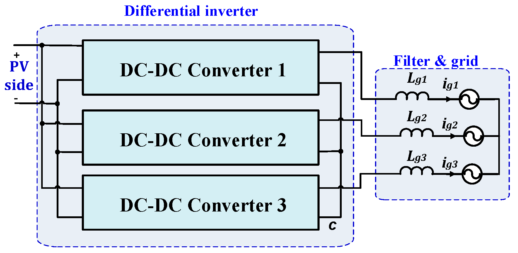
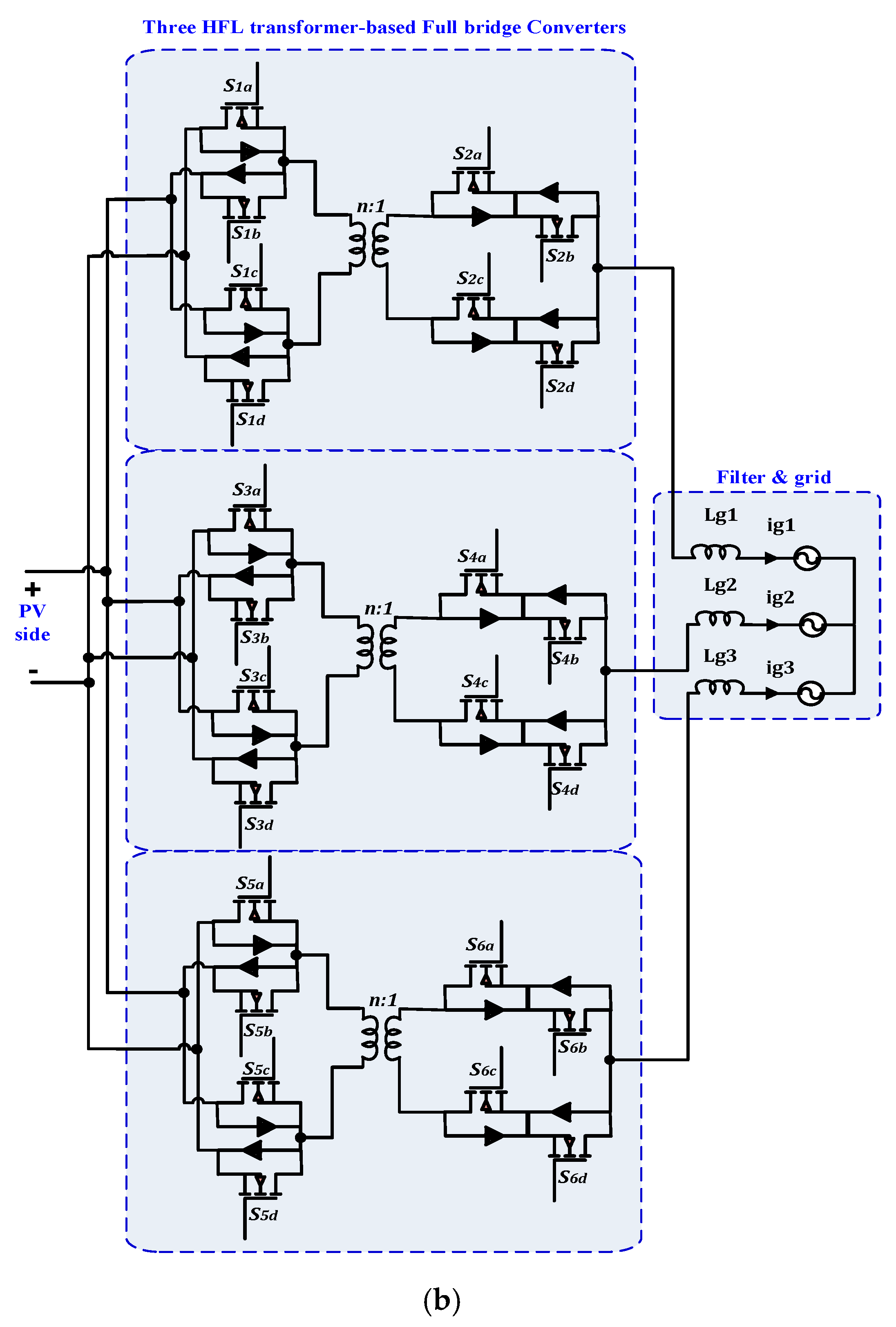
5.1.1. Three-Phase Differential Inverter

Differential Mode Three-Phase Microinverters (DTMI) are single-input single-stage step-up/down topologies. They have high efficiency with a low number of components, hence yielding acceptable total cost and size. Moreover, DTMI topologies can provide bi-directional power transfer. The main drawback of this topology is the voltage stress resulting from the variable duty cycle operation and the circulating current produced from the differential connection of converters.
The block diagram of a DTMI is illustrated in Figure 7. It consists of three DC-DC converters connected in parallel at the input and differentially at the output side. The three-phase output is produced using Sinusoidal Pulse Width Modulation (SPWM) with a 120 phase shift. This inverter can step-up/down the voltage using proper DC-DC converters. The output voltages have both DC and AC components. The DC component values are equal for all phases, and it is cancelled by the differential connection, which is responsible for the voltage stress, while the AC component appearing on the output voltage of each converter are combined to create the sinusoidal AC voltage of the inverter. The diverse characteristics of the DC-DC converters give rise to many differential inverters as previously shown [83,84,85,86,87,88,89,90,91,92,93].
Figure 8; Figure 9 show the various types of the non-isolated and isolated differential mode three-phase microinverter topologies, respectively.
A detailed comparison is provided in Table 1; Table 2 for these differential mode microinverter topologies. Selected topologies called D1 to D6 are listed and illustrated in Table 1, a performance comparison of differential mode microinverter topologies is given. In contrast, Table 2 presents the comparison of voltage stress of differential mode microinverters [83,84,85,86,87,88]. Moreover, the analysis of components counts utilized in three-phase differential microinverter topologies is shown in Figure 10.
The following points summarize these topologies based on the derived mandatory features:
MPPT operation: PV module with its MPPT can be implemented with high tracking efficiency for DC-DC converters with non-pulsating input current such as boost, SEPIC, and Cuk converter topologies [85,89].
CMV: Adding HFL transformer to Cuk and full-bridge, as shown in Figure 8a,b respectively, will eliminate the leakage current and CMV. On the other hand, CMV elimination can be achieved by using proper modulation techniques, especially for transformer-less topologies shown in Figure 9a,d.
High voltage gain: High voltage gain is necessary for microinverter topologies because of the low voltage of PV modules. In buck-boost and boost converters, high voltage can be effectively achieved. Moreover, a very high voltage gain is possible in isolated topologies utilizing the turn ratio of HFL transformer in addition to the conversion gain of the converter keeping in mind the relationship between HFL transformer turns ratio and its efficiency.
Four-wire operation: The four-wire system can be implemented using the previous topologies. It can be implemented by using a split DC-link capacitor (see Figure 4b) or using added four-wire solution (see Figure 4c).
Important features of differential inverter topologies provided in Table 1 are summarized as follows:
DMPPT: DMPPT techniques have not been issued in these topologies because they use a single-input PV module(s).
Electrolytic-less capacitor (E-less cap): Since differential three-phase inverters share small capacitors, they can be used with an electrolytic-less capacitor. Moreover, the parallel connection of theses converters on the input side cancels inherent double line frequency, which leads to the use of small input film capacitors.
Voltage isolation: HFL transformer integration is proposed in topologies shown in Figure 9a,b to increase the power density and achieve voltage isolation. This also increases safety.
Conversion efficiency: The reported maximum efficiency is about 95% for SEPIC topology shown in Figure 8c.
Component count: Figure 10 shows a detailed element counts comparison of differential three-phase microinverters. All passive elements, inductors, and capacitors of DC-DC converters, HFL transformers, and switches are counted. Table 2 gives the switches voltage stresses. It can be noticed that the topology of Figure 8d has the lowest components count among the presented topologies.
Reliability: To support reliability issues, many control techniques such as sliding mode control (SMC) and proportional resonant (PR) have been proposed for topologies shown in Figure 8a and Figure 8b, respectively. From Table 2, the SEPIC converter has the lowest voltage stress. For reliable operation, DCM is proposed in topology D5, and soft switching is proposed in topology D6.
THD: The lowest THD is performed in topology D3, and the maximum reported THD is in topology D1.
Anti-islanding operation: Concerning the previously mentioned PV based differential inverter topologies, there is no discussion about anti-islanding operation. Therefore, it could be of interest to discuss this issue for these topologies in future work.
Reactive power control: Reactive power increases as circulating currents exist and so it is important to assure a good control design that presents the existence of current circulating. The selected topologies D1–D6 should be examined for the existence of circulating current and the reactive power.
DC current injection: This feature should be tested, especially for transformer-less topologies D1–D4.
Voltage and frequency operation: In topologies D1–D6, this issue should be tested in different conditions and different scenarios.

5.1.2. Three-Phase Z Source Inverter

Impedance Z-Source Inverter (ZSI) is a single-input single-stage inverter with few unique features. The ZSI can limit the problematic issues of the VSI and current source topologies and provides a step-up voltage conversion solution. The classical ZSI has an extra circuit called the Z-network, as illustrated in Figure 11. This network improves the inverter’s features by increasing buck/boost conversion gain due to Shoot Through (ST) property, which eliminates the dead time operation required in conventional VSI topologies [94,95].
To avoid the shortcomings of the classical ZSI, many topologies have been derived such as quasi ZSI (qZSI), Switched Inductor (SL-ZSI), combines switched inductor with quasi ZSI (SL-qZSI), Transformer based ZSI (Trans-ZSI), and inductor-based ZSI (L-ZSI) for many applications. These topologies have been presented, reviewed, classified, and evaluated for many applications in other studies (see [95,96,97]). Here, studies on ZSI topologies, when utilized in three-phase microinverter applications, will be carried out, and the topologies will be discussed in more detail.
The classical ZSI topology has low voltage gain with high switching losses and high voltage stress, posing many challenges for PV based three-phase microinverters. In previous studies [98,99], different modulation techniques were used to increase the voltage gain without adding extra elements in the power stage, being able to enhance the boosting capability over a wide range operation. In a study by Barathy, Kavitha, and Viswanathan [99], high gain was achieved by defining the right choice of active vectors and the placement of ST states. In this way, the voltage gain can be increased at high modulation indices. In addition, with the inclusion of ST states, the number of switching is less, which results in low switching losses and low voltage stress and small size of the reactive components.
In contrast to classical ZSI, qZSI topology, shown in Figure 12, has the advantage of continuous input current, which makes it suitable for PV applications. A PV-fed qZSI with optimal control was proposed by Bakeer,. Ismeil, and Orabi [100], where a finite control set model predictive control (FCS-MPC) with reduced computation time was proposed for this system [100].
A modified ZSI (L-ZSI), involving only diodes and inductors for boosting the ratio of the inverter, was proposed by Pan [101] and is shown in Figure 13. The L-ZSI is a modification on the SL-ZSI. The proposed topology provides inrush current suppression because no current flows to the main circuit at start-up. The proposed topology also provides a common ground for the source and inverter.
Utilizing the Z-network, a transformer and a capacitor form another topology called trans-Z-source inverter, as proposed by Qian, Peng, and Cha [102], with reduced components count. Its circuit diagram is shown in Figure 14. The voltage gain and voltage stress are significantly improved by using a transformer’s turn ratio larger than one. Isolated Z-source inverter using HFL transformers is presented by Jiang and co-authors [103] for low voltage applications (Figure 15). This isolated topology introduces extra components because the utilization of HFL transformers requires an additional power conversion stage.
On the other hand, four-leg quasi-ZSI was proposed by Bayhan and co-workers [104], as illustrated in Figure 16. There, Model Predictive Control (MPC) scheme was used to overcome the drawbacks of the classical ZSI. MPC was used to control the load current and quasi ZS network capacitor voltage with high accuracy, leading to a fast response. The proposed controller handles each phase current independently. As a result, the proposed quasi ZS four-leg inverter provides fault-tolerant capability, for example, if one leg fails, the others can work normally. Finally, a three-phase four-leg inverter was employed to ensure the reliable operation of the PV architecture under balanced and unbalanced load conditions.
Table 3 compares the previously discussed Z-source topologies utilized in three-phase microinverters based on some features and standards. Based on the mandatory features, the following statements can be made:
MPPT operation: For high tracking efficiency, continuous input Z-source microinverter topologies such as qZSI [100] are preferred.
CMV: CMV in Z-source microinverter topologies can be mitigated using modified switching states [50]. Moreover, CMV is highly reduced in isolated Z-source [103] topologies.
High voltage gain: For high voltage gain, L-ZSI [101] and voltage fed trans-ZSI [102] are recommended.
Four-wire operation: Four-wire systems [104] for PV-fed Z-source inverters are implemented using a four-leg solution (see Figure 4b).
On the other hand, implementation of three-phase microinverters using Z-source inverter topologies match important features such as:
DMPPT: Based on the authors’ knowledge, DMPPT-related research for PV modules with Z-source inverters was not reported in the literature as it uses a single-input PV source.
Electrolytic-less capacitor (E-less cap): The most effective topology among Z-source microinverter topologies is L-ZSI because the capacitor is totally omitted, resulting in less electrolytic-less capacitor topology. On the other hand, in traditional Z-source microinverters [88,89,94], the Z network’s capacitor is still large and requires an electrolytic capacitor. Finally, for qZSI topology and trans-Z-source topologies [100,102], this capacitor is still 25% larger than the electrolytic-less capacitor.
Voltage isolation: Isolated ZSI [103] is considered a good solution for three-phase microinverters, but it has a high number of components.
Conversion efficiency: The conversion efficiency of Z-source microinverter topologies is still lower than VSI microinverter.
Component cost:Figure 17 presents the number of components of each topology. Classical ZSI, L-ZSI, and QZSI have the lowest number of components, which decrease the overall cost.
Reliability: Table 4 shows the voltage stress of each topology. For a turn ratio equal to 1, all Z-source microinverter topologies have equal switch stress except L-ZSI [101]. The same can be said for capacitor stress except for Z3, which has no capacitors making it more reliable.
THD: The reported THD is 11% and 8.7% in studies by Barathy and collegaues [99] and Bayhan and co-authors [104], respectively.
Anti-islanding operation: According to the previously discussed PV-fed Z-source topologies, there is no discussion about the anti-islanding operation. However, a proper control design, which detects anti-islanding conditions, requires careful integration and design for the previously discussed topologies.
Reactive power control: For all the previously discussed topologies [99,100,101,102,103,104], the reactive power control can be improved by selecting judicious modulation strategies.
DC current injection: This feature should be examined for all the previously discussed Z-source inverter topologies [99,100,101,102,103,104].
Voltage and frequency operation: These features should be tested and improved by using different voltage controllers and different modulation techniques.

5.2. Single-Input Two-Stage Microinverter Topologies

Voltage Source Inverter Topologies

Three-phase VSI usually has a voltage step-down property. For PV systems, they add a boosting stage using a DC-DC boost or some other boost-derived topologies, like buck-boost, isolated boost, and full-bridge converters. For microinverters’ utilization, the main challenge is the increased components’ count that results in high cost and increased size. Much work has been done recently to overcome these disadvantages. In a study by Chen and co-workers [105], the design and implementation of a three-phase grid-connected two-stage MIC with improved efficiency, using ZVS strategy, was proposed. The first stage is an LLC resonant DC-DC full-bridge converter with Center Point Iterations (CPI) MPPT algorithm. The second stage is a full-bridge inverter. In addition, the four-wire system can be adopted, as shown in Figure 18.
Full-bridge LLC resonant converter has many advantages such as high efficiency and capability of ZVS or ZCS operation over a wide range of input voltages. Moreover, phase skipping control can be implemented to improve the inverter efficiency under light load conditions [105]. Finally, triple loop control of ZVS can be achieved and optimized to guarantee the stability of the inverter used in PV applications [106]. A two-stage three-phase VSI, with improved efficiency, was proposed by Huang and Mazumder [107] using a soft switching mechanism based on Zero Voltage Zero Current Switching (ZVZCS) principle. The first stage is an isolated full-bridge DC-DC converter, and the second stage is a three-phase VSI inverter, as shown in Figure 19.
A different two-stage three-phase VSI was proposed by Jain and Singh [98]. The first stage uses a conventional boost converter to perform MPPT control to feed DC power, and the second stage is a two-level VSI, as shown in Figure 20. The proposed system uses an adaptive DC link voltage by adjusting the reference DC link voltage according to the Common Point of Interconnection (CPI) voltage. The adaptive DC link voltage control helps in the reduction of switching losses. A feed forward loop was also used to improve the dynamic response.
To evaluate these topologies utilized in three-phase microinverters, three solutions V1–V3 are compared based on features and standards of three-phase microinverters, as illustrated in Table 5. Based on the derived mandatory features, the following statements can be made:
MPPT operation: For V1, the CPI MPPT algorithm is proposed for high tracking efficiency. For V3, the incremental conductance MPPT controller is reported.
CMV: CMV in V1 and V2 is low due to the utilization of HFL transformer in the full-bridge DC-DC converter. However, CMV is high in V3.
High voltage gain: The most interesting topology is V1, where high gain is attained by using resonance frequency of the LLC resonant DC-DC full-bridge converter.
Four-wire system: Four-wire system approach was adopted in V1 using a split DC capacitor for PV modules.
On the other hand, good design of three-phase microinverters using two-stage VSI topologies must consider other important features:
DMPPT: DMPPT has not been discussed in two-stage VSI inverter topologies V1–V3, as they have a single input PV source. On the other hand, since the first stage can be utilized with multi-input, DMPPT can be achieved.
Electrolytic-less capacitor (E-less cap): For topology V1, the DC link capacitor is only about 35 μF, so that the film capacitor can be used. For topologies V2 and V3, an electrolytic-less capacitor is still needed.
Voltage isolation: HFL isolation can be implemented in topologies V1 and V2.
Conversion efficiency: The highest conversion efficiency, 95.5%, is reported for topology V1. For topology V2, the efficiency is 91.5%.
Component cost: Figure 21 presents the number of components of each topology. V3 topology has the lowest number of components, hence the lowest overall cost.
Reliability: It depends on the component count, voltage stress, and component values. The switching techniques developed in V1 and V2 can improve the overall system reliability.
THD: The reported THD is 5% for all topologies.
Anti-islanding operation: At weak grid operation, the previously discussed two-stage VSI topologies V1–V3 cannot operate in islanding operation mode to feed local loads. Therefore, adding this property for these topologies can enhance conversion power performance, especially in DG applications.
Reactive power control: For all previously discussed topologies V1–V3, several modifications of PWM techniques can enhance these topologies to perform active and reactive power control.
DC Current injection: This feature should be tested for all aforementioned discussed two-stage VSI inverter V1–V3 topologies.
Voltage and frequency operation: In topologies V1–V3, the output voltage control was applied, but it needs more tests and investigation.

5.3. Multi-Input Microinverter Topologies

Multi-input microinverter topologies can substitute separate single-input three-phase microinverters and reduce the components count and cost. This multi-input design approach is receiving interest due to the launching of distributed renewable energy sources, such as PV, in recent utility grids and due to the requirement of integrating different kinds of renewable energy resources in a hybrid system, such as PV and wind. Moreover, DMPPT controllers, which optimize the operation of independent PV modules, can be integrated with independent controllers even at partial shading conditions. However, the main issue of theses topologies is how to incorporate different stable and robust DMPPT controllers of PV modules. The following lines discuss the interesting topologies of multi-input three-phase microinverters.
Three-phase Multi-Level Inverter (MLI) topologies have been utilized in low-power applications, such as PV module architectures for its inherent features such as [109]:
Staircase output voltage waveform partially following a sine wave template leads to a low THD with high voltage levels and low voltage stress.
Using MLI reduces the voltage transient stresses.
Low CMV is introduced in MLIs utilizing split capacitors and proper PWM modulation techniques.
Low switching loss is due to low switching frequency.
Low distortion in the input current leads to high tracking efficiency of PV modules.
Moreover, there are many challenges for MLIs, especially when utilized as microinverters and PV module interfaces. Their main drawbacks are:
Low voltage gains less than unity; therefore, a boost stage is added to increase the voltage hence leading to the use of more components.
Reliability concerns due to non-uniform voltage stress and distributed losses.
The high transient voltage across the clamped switches is introduced for grid-connected PV architectures.
Interestingly, many works have been published to compare and evaluate the intensive literature work of MLI topologies [110,111]. However, the vast majority of these works focused on THD, switches count, and inverters control. Below, the topologies considering multi-input three-phase microinverters based on the classification shown in Figure 5 are discussed in detail.

5.3.1. Cascaded H-Bridge (CHB) Inverter Topologies

Cascaded H-Bridge (CHB) MLIs are considered the simplest multi-level topologies. They are obtained by connecting the output of full H-bridge modules in series as illustrated in Figure 22.
One of the most interesting features of this topology is the ability to boost the PV voltage in the staircase form since each PV voltage is considered as one level of the output voltage. As can be observed in Figure 23, the maximum output voltage of the circuit is equal to   V pv 1 + V pv 2 [111]. In [113], the same multi-input three-phase microinverters with different PV modules for each H-bridge were discussed by Rivera and co-workers. DMPPT controllers were applied to guarantee maximum power extraction from each PV module. This topology can be used to increase the voltage gain by adding more levels. It improves the efficiency and modularity and allows independent control for each phase. However, this topology’s main issue is the mismatches between the PV sources, which leads to unbalanced sources causing an unbalanced grid current.
In a study by Xiao and co-authors [61], a control scheme with modulation compensation was introduced by using a zero-sequence current to make the unbalanced power proportional to unbalanced output voltage. The key issue is the complexity of the control. Moreover, the modulation index of each PV module could violate its bands at high or severe PV mismatching conditions. To simplify this control, a DC power control method was proposed by Ye and co-authors [112] to make the PV power at mismatch conditions and related modulation indices at their expected values. In a study by Sochor and Akagi [114], the power balancing of PV modules in modular three-phase CHB is discussed and compared for two different configurations. Theoretical comparison of single-star bridge cells and single-delta bridge cells reveals that the second configuration, shown in Figure 23, mitigates the unbalance between the signals, which simplifies the modulation compensation control.
The following statements can be made for the previous topologies according to the mandatory factors:
MPPT operation: MPPT is applied due to independent control of DC-link voltage. However, at severe PV mismatching conditions, this control can fail to select optimum weighing factors between MPPT efficiency of each PV module and output current balance on the grid side [112].
CMV: CMV in each H-bridge exists, then different control techniques are used to improve it.
High voltage gain: the high voltage conversion ratio can be increased by adding PV modules to increase output voltage stairs with high modularity and flexibility.
Four-wire operation: The four-wire operation approach was not reported in these topologies. Although, implementing a four-wire multi-input multi-level three-phase microinverter could be interesting in future PV applications.
On the other hand, the design of three-phase microinverter using modular CHB inverter topologies must consider other important features:
DMPPT: DMPPT in all discussed topologies [61,112,113,114] is utilized effectively due to independent control of the DC link of H-bridge, where an MPPT controller for each PV module is appended to generate DC link voltage reference signal.
Electrolytic-less capacitor (E-less cap): Unfortunately, the aforementioned modular CHB inverter topologies have large electrolyte capacitors due to independent control of each phase, which is similar to single-phase inverter topologies. Therefore, novel solutions to decouple these capacitors could be the subject of future work.
Voltage isolation: Up to date, utilizing HFL in multi-input multi-level CHB three-phase inverters has not been proposed.
Conversion efficiency: Higher efficiency is expected for most MLIs due to the absence of passive elements. However, no information about this was reported in the literature.
Component cost: All the discussed topologies have the same component count, so they have the same cost for the power stage. However, the controller complexity and its cost could be different.
Reliability: Although these topologies could enhance the overall reliability by eliminating boost DC-DC converters, they have complex controllers which pose reliability problems. Therefore, working on control simplicity could be a topic of interesting research work.
THD: the reported THD is 3.3% according to [61].
Anti-islanding operation: According to the existing works on the previous CHB topologies, there is no discussion about anti-islanding operation. However, proper control design with high accurate anti-islanding detection is preferred.
Reactive power control: Good controller design can improve the reactive power control.
DC current injection: It is not reported here and based on IEEE 1547 standard; it is specified to be less than 0.5% of the rated output current of up to 1% based on IEC 61727.
Voltage and frequency operation: IEC 62446 for PV system and IEC 61683 standard for inverter testing, in addition to the IEEE 1547 standard, defines the range of voltage frequency variation at the coupling point with the grid. Then, all systems should control its generated power with the voltage control and frequency limit.

5.3.2. Two-Stage Multi-Input VSI Topologies

DC optimizers in PV architectures are extensively utilized due to independent control between DMPPT on each PV module and grid side control at string inverter. These architectures process the power over two stages by DC optimizers first and secondly by string inverter. To reduce the component count and overall cost, and based on modification in the previous architecture, a multi–input three switches leg microinverter, shown in Figure 24, is proposed in [60]. The number of switches is reduced by one in each leg compared to traditional PV architectures. Moreover, the DMPPT for each DC optimizer stage is accomplished by using gate signals on the nearest two switches to the inductor. The middle switch in each leg is utilized for inverter operation.
According to mandatory factors, the following statements can be made for the multi-input two-stage three-phase microinverters proposed in [60]:
MPPT operation: MPPT is applied and controlled by the boost converter on each input.
CMV: CMV can be obtained by using a proper controller.
High voltage gain: A high voltage gain can be obtained by increasing the voltage gain of the conventional (boost) DC optimizer or by using isolated DC-DC converters with a high turns ratio for their HFL transformer.
Four-wire operation: Four-wire operation approach was not reported for this topology.
For important factors, the following are discussed:
DMPPT: DMPPT in the proposed topology is obtained by control of the DC optimizer boost on each input. Therefore, at partial shading conditions, each boost converter operates independently to extract the maximum power that the corresponding source can provide independently of the other sources.
Electrolytic-less capacitor (E-less cap): DC link capacitor is similar to the capacitor utilized in single-input two-stage microinverters.
Voltage isolation: This feature is not reported for this topology. This can be obtained by using isolated DC-DC converters such as flyback and isolated SEPIC converters.
Conversion efficiency: The reported conversion efficiency is about 87% [106].
Component cost: It is considered a low cost compared to the traditional two stages of VSI-based PV systems.
Reliability: The control has two loops, the internal one for current and the external one for voltage. Simplifying this control can enhance overall reliability.
THD: No information was reported about the THD for this topology.
Anti-islanding operation: No information was reported about the anti-islanding operation in this topology.
Reactive power control: This feature is not reported for this topology.
DC current injection: It is not reported here and based on IEEE 1547 standard; it is specified to be less than 0.5% of the rated output current of up to 1% based on IEC 61727.
Voltage and frequency operation: This issue should be tested in different conditions and different scenarios.

6. Discussion of Three-Phase Microinverter Topologies

According to the previous two sections and the selected topologies evaluated by the developed mandatory factors, the following statements can be made:
  • The best topologies of differential microinverters are HFL-based SEPIC and Cuk differential topologies.
  • The best topology at Z-source microinverters is L-ZSI topology.
  • The best topology at two-stage VSIs is LLC resonant microinverter.
In order to fill the gap between the other requirements (important ones) of three-phase microinverters (Section 4) and the selected topologies (Section 5), this section adds another benchmarking strategy. This strategy discusses how each topology can fulfill these requirements and has three different levels:
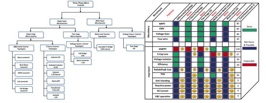
Level 1 (done): This means that this topology implemented this feature in the literature. It gets a full mark.
Level 2 (not done but it is possible): This level examines the topology’s capability to achieve the required feature through extension by added circuit/technique in the future. It gets an average mark.
Level 3 (impossible): This means the impossibility of the topology to fulfill the required three-phase microinverter features. It gets a zero mark.
It is worth noticing that this strategy, with its three levels, adds a new dimension to the previously developed two dimensions (two-stage screening of this work in the last two sections) which will make a general picture with a three-dimensional view. This three-dimensional picture can help the designers and researchers on three-phase microinverters to understand each group’s strong points and how each one fulfills every factor. The three-dimensional picture, shown in Figure 25, can save substantial time during the selection stage of three-phase microinverter design. Moreover, it can make the right decisions about desired microinverter performance on the DC and AC sides.
Based on the above picture with its specified marking system and the discussed detailed features of three-phase selected microinverter topologies under study, it is interesting to note that:
The primary weakness of single-input microinverters (including differential, Z-source, and two-stage VSI topologies) is the DMPPT because it could lead to phase unbalances.
The main shortcoming of multi-input inverter topology is its disability to minimize the employed electrolytic capacitor. Solving this issue using different decoupling techniques will enhance converter reliability.
As illustrated in Figure 25, mandatory features are fulfilled in the Z-source and two-stage VSI topologies. However, most topologies of Z-source inverters still suffer from the use of electrolytic capacitors, which increase size and cost (low mark) in addition to efficiency and other essential factors.
Two-stage VSI topologies need more attention for the last four essential features in addition to reliability and cost. Differential inverter topologies seem to prevail in price and size due to the utilization of the small passive elements of DC-DC converters, which improve efficiency. This target can be achieved by devoting more focus on voltage stress and circulating current and its resultant power losses.
Moreover, four-wire systems, MPPT, and other important features open the door for research and industry to introduce better solutions.
Multi-input multi-level microinverter topologies show the high mark in DMPPT eliminations, reducing the use of electrolyte capacitors, and improving overall efficiency.
The last essential features, such as anti-islanding, reactive power, DC injected current and voltage and frequency operation, have not been reported and examined for all groups.
Finally, the details about each group of the selected topologies are shown Table 6. The numbering in this table corresponds to the same details as in Figure 23 and Table 6.

7. Conclusions

The ongoing development on electrical energy generation using PV-based architectures, such as integrated AC modules, drive research and industry to pay more attention to microinverters. Three-phase inverters are a superior solution to design an electrolyte-less microinverter. This kind of microinverter improves reliability and reduces size and cost when compared to single-phase microinverters. It can also integrate grid features such as islanding, active and reactive power control, ancillary services, etc. This is the door for researchers to investigate three-phase inverter topologies and their control. In addition, it is crucial to compare three-phase inverters based on a developed benchmark or specification that integrates all required features for DC-PV and AC grid sides. In this paper, the standardized features for three-phase microinverters are discussed, classified, and benchmarked. These features have been divided into mandatory and essential factors. Most of the existing microinverter topologies in the literature have been studied and examined based on this developed classification. It has been shown that the primary weakness of single-input microinverters, including differential, Z-source, and two-stage VSI topologies, is the DMPPT due to the phases unbalance issue. Furthermore, the main drawback of multi-input inverter topologies is their inability to reduce the use of electrolytic capacitors. Solving this issue using different decoupling techniques will enhance inverter reliability. Mandatory features are fulfilled in the Z-source and two-stage VSI topologies. However, most Z-source inverter topologies still suffer from the use of electrolytic capacitors which increase the size and cost and degrade the efficiency as well as other essential factors. More attention has to be paid to two-stage VSI topologies due to their essential features in addition to reliability and cost. Differential inverter topologies seem to prevail in price and size due to the utilization of the small passive elements of DC-DC converters which improve efficiency. More focus on voltage stress and circulating current and its resultant power losses must be made. Multi-input multi-level microinverter topologies are the best choice in DMPPT elimination reducing the electrolyte capacitor and improving overall efficiency.

Author Contributions

A.S. did the required survey, analyzed the work, reported the results, and shared in the writing of the manuscript; M.O. proposed the strategy and stated the methodology and reviewed the reported results; M.A. and A.E.A. were responsible for the guidance and number of key suggestions in addition to the editing and review of the written manuscript. All authors have read and agreed to the published version of the manuscript.

Funding

A.S., M.E.A., and M.O. would like to express their gratitude to Aswan Power Electronic Applications Research Center (APEARC), Aswan University for their immense support under STDF grant ID: 15261. A.E.A. would like to thank the Spanish Agencia Estatal de Investigación (AEI) and the Fondo Europeo de Desarrollo Regional (FEDER) under grant DPI2017-84572-C2-1-R (AEI/FEDER, UE).

Acknowledgments

This work was funded in part by the Egyptian Science and Technology Development Funds (STDF) project ID: 15261. Any opinions, findings, and conclusions or recommendations expressed in this material are those of the author(s) and do not necessarily reflect the views of the funding agencies.

Conflicts of Interest

The authors declare no conflicts of interest.

References

  1. Hasanuzzaman, M.; Zubir, U.S.; Ilham, N.I.; Che, H.S. Global electricity demand, generation, grid system, and renewable energy polices: A review. Wiley Interdiscip. Rev. Energy Environ. 2016, 6, e222. [Google Scholar] [CrossRef]
  2. Nadeau, M. World Energy Scenarios World Energy Council. 2016. Available online: www.worldenergy.org (accessed on 1 January 2016).
  3. US Energy Information Administration (EIA). International Energy Outlook 2013 with Projection to 2040. Available online: http://www.eia.gov/forecasts/ieo/ (accessed on 1 July 2013).
  4. US Energy Information Administration (EIA). Annual Energy Outlook 2017 with Projections to 2050; EIA: Washington, DC, USA, 2017.
  5. European Photovoltaic Industry Association (EPIA). Global Market Outlook for Photovoltaic until 2016; European Photovoltaic Industry association (EPIA): Brussels, Belgium, May 2012. [Google Scholar]
  6. Moutinho, V.; Robaina, M. Is the share of renewable energy sources determining the CO2 kWh and income relation in electricity generation? Renew. Sustain. Energy Rev. 2016, 65, 902–914. [Google Scholar] [CrossRef]
  7. Ardian, K. Solar Technologies Market Report; National Renewable Energy Laboratory (NREL): Golden, CO, USA, 2010. [Google Scholar]
  8. Hoffmann, W. PV on the Way from a few lead markets to a world market. In Proceedings of the 4th IEEE World Conference on Photovoltaic Energy Conversion, Waikoloa, HI, USA, 7–12 May 2006; pp. 2454–2456. [Google Scholar] [CrossRef]
  9. Feldman, D.; Barbose, G.; Margolis, R.; Wiser, R.; Darghouth, N.; Goodrich1, A. Photovoltaic (PV) Pricing Trends: Historical, Recent, and Near-Term Projections; Report, SunShot; US Department of Energy: Washington, DC, USA, 2012. [Google Scholar]
  10. Petrakopoulou, F. On the economics of stand-alone renewable hybrid power plants in remote regions. Energy Convers. Manag. 2016, 118, 63–74. [Google Scholar] [CrossRef] [Green Version]
  11. Torreglosa, J.P.; Garcia-Trivino, P.; Fernandez-Ramirez, L.M.; Jurado, F. Control based on techno-economic optimization of renewable hybrid energy system for stand-alone applications. Expert Syst. Appl. 2016, 51, 59–75. [Google Scholar] [CrossRef]
  12. Cristóbal-Monreal, I.R.; Dufo-López, R. Optimization of photovoltaic–diesel–battery stand-alone systems minimising system weight. Energy Convers. Manag. 2016, 119, 279–288. [Google Scholar] [CrossRef]
  13. Sujitha, N.; Krithiga, S. RES based EV battery charging system: A review. Renew. Sustain. Energy Rev. 2017, 75, 978–988. [Google Scholar] [CrossRef]
  14. Ackermann, T.; Andersson, G.; Söder, L. Distributed generation: A definition. Electr. Power Syst. Res. 2001, 57, 195–204. [Google Scholar] [CrossRef]
  15. Zhao, Z.; Yin, L.; Sun, X.; Yuan, L.; Lu, T. Recent Development of Technology and Market of Grid-connected PV System in China. In Proceedings of the International Conference on Electrical Machines and Systems, (ICEMS), Incheon, Korea, 10–13 October 2010; pp. 1–6. [Google Scholar]
  16. Kouro, S.; Leon, J.I.; Vinnikov, D.; Franquelo, L.G. Grid-Connected Photovoltaic Systems: An Overview of Recent Research and Emerging PV Converter Technology. IEEE Ind. Electron. Mag. 2015, 9, 47–61. [Google Scholar] [CrossRef]
  17. Alluhaybi, K.; Batarseh, I. Review and Comparison of Single-Phase Grid-Tied Photovoltaic Microinverters. In Proceedings of the IEEE Energy Conversion Congress and Exposition (ECCE), Portland, OR, USA, 23–27 September 2018. [Google Scholar]
  18. Shawky, A. Development of Power Management Systems for Advanced Photovoltaic Architectures. Master’s Thesis, Aswan University, Aswan, Egypt, May 2014. Chapter 1. [Google Scholar]
  19. Li, Q.; Wolfs, P. A Review of the Single-phase Photovoltaic Module Integrated Converter Topologies with Three Different DC Link Configurations. IEEE Trans. Power Electron. 2008, 23, 1320–1333. [Google Scholar]
  20. Meneses, D.; Blaabjerg, F.; Garcia, O.; Cobos, J.A. Review and Comparison of Step-Up Transformer less Topologies for Photovoltaic AC-Module Application. IEEE Trans. Power Electron. 2013, 28, 2649–2663. [Google Scholar] [CrossRef] [Green Version]
  21. Shawky, A.; Shier, A.; Orabi, M.; Qahouq, J.A.M. Youssef High Efficiency Single-stage Current Source Inverter for Photovoltaic Applications. In Proceedings of the 35th IEEE International Telecommunication Energy Conference (INTELEC 2013), Hamburg, Germany, 13–17 October 2013. [Google Scholar]
  22. Shawky, A.; Orabi, M.; Qahouq, J.A.; Youssef, M. Development and comparative evaluation of power management systems for advanced photovoltaic architectures. In Proceedings of the International Telecommunication Energy Conference (INTELEC 2014), Vancouver, BC, Canada, 28 September–2 October 2014. [Google Scholar]
  23. Petrone, G.; Spagnuolo, G.; Teodorescu, R.; Veerachary, M.; Vitelli, M. Reliability Issues in Photovoltaic Power Processing Systems. IEEE Trans. Ind. Electron. 2008, 55, 2569–2580. [Google Scholar] [CrossRef]
  24. Pilawa-Podgurski, R.C.N.; Perreault, D.J. Submodule Integrated Distributed Maximum Power Point Tracking for Solar Photovoltaic Applications. IEEE Trans. Power Electron. 2012, 28, 2957–2967. [Google Scholar] [CrossRef] [Green Version]
  25. Shenoy, P.S.; Kim, K.; Johnson, B.B.; Krein, P.T. Differential Power Processing for Increased Energy Production and Reliability of Photovoltaic Systems. IEEE Trans. Power Electron. 2013, 28, 1795–1806. [Google Scholar] [CrossRef]
  26. Shawky, A.; Helmy, F.; Orabi, M.; Qahouq, J.A.; Dang, Z. On chip integrated Cell-Level power management Architecture with MPPT for PV Solar System. In Proceedings of the IEEE Applied Power Electronics Conference, APEC, Fort Worth, TX, USA, 16–20 March 2014. [Google Scholar]
  27. Shawky, A.; Helmy, F.; Orabi, M.; Ahmed, E.M.; Qahouq, J.A.A. A Single Cell Integrated Photovoltaic Converter Based on Buck-Boost Topology with RCC MPPT Control. In Proceedings of the IEEE International Telecommunication Energy Conference (INTELEC), Hamburg, Germany, 13–17 October 2013. [Google Scholar]
  28. Orabi, M.; Hilmy, F.; Shawky, A.; Abu Qahouq, J.A.; Hasaneen, E.-S.; Gomaa, E. On-chip integrated power management MPPT controller utilizing cell-level architecture for PV solar system. Sol. Energy 2015, 117, 10–28. [Google Scholar] [CrossRef] [Green Version]
  29. Shawky, A.; Radwan, H.; Orabi, M.; Youssef, M. A Novel Platform for an Accurate Modeling and Precise Control of Photovoltaic Modules with Maximum Operating Efficiency. In Proceedings of the IEEE Applied Power Electronics Conference & Exposition, Charlotte, NC, USA, 15–19 March 2015. [Google Scholar]
  30. Zhou, H.; Zhao, J.; Han, Y. PV Balancers: Concept, Architectures, and Realization. IEEE Trans. Power Electron. 2015, 30, 3479–3487. [Google Scholar] [CrossRef]
  31. MacAlpine, S.; Deline, C. Modeling Microinverters and DC Power Optimizers in PVWatts; Technical Report NREL/TP-5J00-63463; National Renewable Energy Laboratory (NREL): Golden, CO, USA, 2015. [Google Scholar]
  32. Reinders, A.; Verlinden, P.; van Sark, W.; Freundlich, A. Photovoltaic Solar Energy: From Fundamentals to Applications. In Inverters, Power Optimizers and Microinverters, 1st ed.; John Wiley & Sons, Ltd.: Hoboken, NJ, USA, 2017; Chapter 11. [Google Scholar]
  33. Deline, C.; MacAlpine, S. Use conditions and efficiency measurements of DC power optimizers for photovoltaic systems. In Proceedings of the 2013 IEEE Energy Conversion Congress and Exposition, Denver, CO, USA, 15–19 September 2013; pp. 4801–4807. [Google Scholar]
  34. Strache, S.; Wunderlich, R.; Heinen, S. A Comprehensive, Quantitative Comparison of Inverter Architectures for Various PV Systems, PV Cells, and Irradiance Profiles. IEEE Trans. Sustain. Energy 2014, 5, 813–822. [Google Scholar] [CrossRef]
  35. Mazumdar, P.; Enjeti, P.N.; Balog, R.S. Analysis and Design of Smart PV Modules. IEEE J. Emerg. Sel. Top. Power Electron. 2014, 2, 451–459. [Google Scholar] [CrossRef]
  36. Beng, J.M. Advances in Commercial Applications of Photovoltaic Technology in North America: 2009 Update. In Proceedings of the IEEE PES General Meeting, Providence, RI, USA, 25-29 July 2010. [Google Scholar]
  37. SMA Solar Inverters “SB5000TL21 SMA 5 kW Single Phase TL Solar Inverter”. Available online: https://www.sma-america.com/products/solarinverters.html (accessed on 19 May 2017).
  38. Enphase Energy. Enphase Energy Commercial PV Using the Enphase M-Series Microinverter System; Design Guide: California CA, USA, 2015. [Google Scholar]
  39. Hu, H.; Harb, S.; Kutkut, N.; Batarseh, I.; Shen, Z.J. A Review of Power Decoupling Techniques for Microinverters with Three Different Decoupling Capacitor Locations in PV Systems. IEEE Trans. Power Electron. 2012, 28, 2711–2726. [Google Scholar] [CrossRef]
  40. Sun, Y.; Liu, Y.; Su, M.; Xiong, W.; Yang, J. Review of Active Power Decoupling Topologies in Single-Phase Systems. IEEE Trans. Power Electron. 2015, 31, 4778–4794. [Google Scholar] [CrossRef]
  41. Hasan, R.; Mekhilef, S.; Seyedmahmoudian, M.; Horan, B. Grid-connected isolated PV microinverters: A review. Renew. Sustain. Energy Rev. 2017, 67, 1065–1080. [Google Scholar] [CrossRef]
  42. Bush, C.R.; Wang, B. A single-phase current source solar inverter with reduced-size dc link. In Proceedings of the IEEE Energy Conversion Congress & Exposition, San Jose, CA, USA, 20–24 September 2009; pp. 54–59. [Google Scholar]
  43. Somani, U. Design Optimization of LLC Topology and Phase Skipping Control of Three-phase Inverter for PV Applications. Master’s Thesis, University of Central Florida, Orlando, FL, USA, September 2013. [Google Scholar]
  44. Ji, Y.-H.; Jung, D.-Y.; Kim, J.-G.; Lee, T.-W.; Kim, J.-H.; Won, C.-Y. A Real Maximum Power Point Tracking Method for Mismatching Compensation in PV Array under Partially Shaded Conditions. IEEE Trans. Power Electron. 2010, 26, 1001–1009. [Google Scholar] [CrossRef]
  45. Manickam, C.; Raman, G.P.; Raman, G.; Ganesan, S.I.; Chilakapati, N. Fireworks Enriched P&O Algorithm for GMPPT and Detection of Partial Shading in PV Systems. IEEE Trans. Power Electron. 2016, 32, 4432–4443. [Google Scholar]
  46. Nguyen, T.-K.T.; Nguyen, N.-V.; Prasad, N.R. Eliminated common-mode voltage pulsewidth modulation to reduce output current ripple for multilevel inverters. IEEE Trans. Power Electron. 2015, 31, 5952–5966. [Google Scholar] [CrossRef]
  47. Le, Q.A.; Lee, D.C. Modified SVPWM to eliminate common-mode voltages for five-level ANPC inverters. In Proceedings of the IEEE Energy Conversion Congress and Exposition (ECCE), Milwaukee, WI, USA, 18–22 September 2016; pp. 1–6. [Google Scholar]
  48. Videt, A.; Messaoudi, M.; Idir, N.; Boulharts, H.; Vang, H. PWM Strategy for the Cancellation of Common-Mode Voltage Generated by Three-Phase Back-to-Back Inverters. IEEE Trans. Power Electron. 2016, 32, 2675–2686. [Google Scholar] [CrossRef]
  49. Basu, K.; Umarikar, A.C.; Mohapatra, K.K.; Mohan, N. High-frequency transformer-link three-level inverter drive with common-mode voltage elimination. In Proceedings of the 2008 IEEE Power Electronics Specialists Conference, Rhodes, Greece, 15–19 June 2008; pp. 4413–4418. [Google Scholar]
  50. Lyden, S.; Haque, M.E. Comparison of the perturb and observe and simulated annealing approaches for maximum power point tracking in a photovoltaic system under partial shading conditions. In Proceedings of the IEEE Energy Convers Congress Exposition, Pittsburgh, PA, USA, 14–18 September 2014; pp. 2517–2523. [Google Scholar]
  51. Tey, K.S.; Mekhilef, S. Modified Incremental Conductance Algorithm for Photovoltaic System under Partial Shading Conditions and Load Variation. IEEE Trans. Ind. Electron. 2014, 61, 5384–5392. [Google Scholar]
  52. Sen, T.; Pragallapati, N.; Agarwal, V.; Kumar, R. Global maximum power point tracking of PV arrays under partial shading conditions using a modified particle velocity-based PSO technique. IET Renew. Power Gener. 2018, 12, 555–564. [Google Scholar] [CrossRef]
  53. Li, H.; Yang, D.; Su, W.; Lu, J.; Yu, X. An Overall Distribution Particle Swarm Optimization MPPT Algorithm for Photovoltaic System under Partial Shading. IEEE Trans. Ind. Electron. 2019, 66, 265–275. [Google Scholar] [CrossRef]
  54. Bossche, A.P.V.D.; Haddad, S.; Mordjaoui, M. Power electronic converters without electrolytic capacitors. Int. J. Renew. Energy Technol. 2019, 10, 83–92. [Google Scholar] [CrossRef] [Green Version]
  55. Hu, H.; Harb, S.; Kutkut, N.; Shen, Z.J.; Batarseh, I. A Single-Stage Microinverter without Using Eletrolytic Capacitors. IEEE Trans. Power Electron. 2013, 28, 2677–2687. [Google Scholar] [CrossRef]
  56. Da Fonseca, Z.P.; Badin, A.A.; Nascimento, C.B. Single stage high power factor converter using coupled input boost inductor BCM without eletrolytic capacitor to drive power LED. In Proceedings of the 2016 12th IEEE International Conference on Industry Applications (INDUSCON), Curitiba, Brazil, 20–23 November 2016. [Google Scholar]
  57. Azizi, M.; Mohamadian, M.; Beiranvand, R. A New Family of Multi-Input Converters Based on Three Switches Leg. IEEE Trans. Ind. Electron. 2016, 63, 6812–6822. [Google Scholar] [CrossRef]
  58. Hu, Y.; Wu, J.; Cao, W.; Xiao, W.; Li, P.; Finney, S.J.; Li, Y. Ultra-High Step-up DC-DC Converter for Distributed Generation by Three Degrees of Freedom (3DoF) Approach. IEEE Trans. Power Electron. 2015, 31, 4930–4941. [Google Scholar] [CrossRef] [Green Version]
  59. Liu, H.; Hu, H.; Wu, H.; Xing, Y.; Batarseh, I. Overview of High-Step-Up Coupled-Inductor Boost Converters. IEEE J. Emerg. Sel. Top. Power Electron. 2016, 4, 689–704. [Google Scholar] [CrossRef]
  60. Melo, F.C.; Garcia, L.S.; De Freitas, L.C.; Coelho, E.A.A.; Farias, V.J.; De Freitas, L.C.G. Proposal of a Photovoltaic AC-Module With a Single-Stage Transformerless Grid-Connected Boost Microinverter. IEEE Trans. Ind. Electron. 2018, 65, 2289–2301. [Google Scholar] [CrossRef]
  61. Xiao, B.; Hang, L.; Mei, J.; Riley, C.; Tolbert, L.M.; Ozpineci, B. Modular Cascaded H-Bridge Multilevel PV Inverter With Distributed MPPT for Grid-Connected Applications. IEEE Trans. Ind. Appl. 2014, 51, 1722–1731. [Google Scholar] [CrossRef]
  62. Dai, M.; Marwali, M.N.; Jung, J.-W.; Keyhani, A. A Three-Phase Four-Wire Inverter Control Technique for a Single Distributed Generation Unit in Island Mode. IEEE Trans. Power Electron. 2008, 23, 322–331. [Google Scholar] [CrossRef]
  63. Sinsukthavorn, W.; Ortjohann, E.; Mohd, A.; Hamsic, N.; Morton, D. Control Strategy for Three-/Four-Wire-Inverter-Based Distributed Generation. IEEE Trans. Ind. Electron. 2012, 59, 3890–3899. [Google Scholar] [CrossRef]
  64. Meersman, B.; Renders, B.; Degroote, L.; Vandoorn, T.; Kooning, J.D.; Vandevelde, L. Overview of three-phase inverter topologies for distributed generation purposes. In Proceedings of the Innovation for Sustainable Production conference, i-SUP 2010, Bruges, Belgium, 18–21 April 2010. [Google Scholar]
  65. Zong, Q.C.; Liang, J.; Weiss, G.; Feng, C.; Timothy, T.C. H ∞ Control of the Neutral Point in Four-Wire Three-phase DC-AC converters. IEEE Trans. Ind. Electron. 2006, 53, 1594–1602. [Google Scholar] [CrossRef]
  66. Bifaretti, S.; Lidozzi, A.; Solero, L.; Crescimbini, F. Modulation with Sinusoidal Third-Harmonic Injection for Active Split DC-Bus Four-Leg Inverters. IEEE Trans. Power Electron. 2015, 31, 6226–6236. [Google Scholar] [CrossRef]
  67. De, D.; Ramanarayanan, V. A DC-to-Three-Phase-AC High-Frequency Link Converter with Compensation for Nonlinear Distortion. IEEE Trans. Ind. Electron. 2010, 57, 3669–3677. [Google Scholar] [CrossRef]
  68. Zhao, C.; Trento, B.; Jiang, L.; Jones, E.A.; Liu, B.; Zhang, Z.; Costinett, D.; Wang, F.F.; Tolbert, L.M.; Jansen, J.F.; et al. Design and Implementation of GaN-Based, 100 kHz, 102W/in3 Single-Phase Inverter. IEEE J. Emerg. Sel. Top. Power Electron. 2016, 4, 824–840. [Google Scholar] [CrossRef]
  69. Almasoudi, F.M.; Alatawi, K.S.; Matin, M. Design of isolated interleaved boost DC-DC converter based on SiC power devices for microinverter applications. In Proceedings of the 2016 North American Power Symposium (NAPS), Denver, CO, USA, 18–20 September 2016; pp. 1–6. [Google Scholar]
  70. Suda, J. SiC and GaN from the viewpoint of vertical power devices. In Proceedings of the 2016 74th Annual Device Research Conference (DRC), Newark, DE, USA, 19–22 June 2016. [Google Scholar]
  71. Orabi, M.; Shawky, A. Proposed Switching Losses Model for Integrated Point-of-Load Synchronous Buck Converters. IEEE Trans. Power Electron. 2014, 30, 5136–5150. [Google Scholar] [CrossRef]
  72. Zhang, D.; Zhang, Q.; Grishina, A.; Amirahmadi, A.; Hu, H.; Shen, J.; Batarseh, I. A comparison of soft and hard-switching losses in three-phase microinverters. In Proceedings of the 2011 IEEE Energy Conversion Congress and Exposition, Phoenix, AZ, USA, 17–22 September 2011; pp. 1076–1082. [Google Scholar]
  73. Cha, H.J.; Enjeti, P.N. A new soft switching direct converter for residential fuel cell power system. In Proceedings of the 39th IAS Annual Meeting of IEEE Industry Applications Society, Seattle, WA, USA, 3–7 October 2004; pp. 1172–1177. [Google Scholar]
  74. Sidrach-De-Cardona, M.; Carretero, J. Analysis of the current total harmonic distortion for different single-phase inverters for grid-connected pv-systems. Sol. Energy Mater. Sol. Cells 2005, 87, 529–540. [Google Scholar] [CrossRef]
  75. Ahmed, M.; Orabi, M.; Ghoneim, S.; Alharthi, M.; Salem, F.; Alamri, B.; Mekhilef, S. General Mathematical Solution for Selective Harmonic Elimination. IEEE J. Emerg. Sel. Top. Power Electron. 2019, 1. [Google Scholar] [CrossRef]
  76. Estébanez, E.J.; Moreno, V.M.; Pigazo, A.; Liserre, M. An overview of anti-islanding detection algorithms in photovoltaic systems in case of multiple current-controlled inverters. In Proceedings of the 2009 35th Annual Conference of IEEE Industrial Electronics, Porto, Portugal, 3–5 November 2009; pp. 4555–4560. [Google Scholar]
  77. Morstyn, T.; Hredzak, B.; Agelidis, V. Control Strategies for Microgrids with Distributed Energy Storage Systems: An Overview. IEEE Trans. Smart Grid 2016, 9, 3652–3666. [Google Scholar] [CrossRef] [Green Version]
  78. Ndiaye, I.; Wu, X.; Agamy, M. Impact of microinverter reactive power support capability in high penetration residential PV networks. In Proceedings of the 2015 IEEE 42nd Photovoltaic Specialist Conference (PVSC), New Orleans, LA, USA, 14–19 June 2015; pp. 1–6. [Google Scholar]
  79. Yan, G.; Cai, Y.; Jia, Q.; Liang, S. Stability analysis of grid-connected PV generation with an adapted reactive power control strategy. J. Eng. 2019, 2019, 2980–2985. [Google Scholar] [CrossRef]
  80. Hashemi, S.; Ostergaard, J. Methods and strategies for overvoltage prevention in low voltage distribution systems with PV. IET Renew. Power Gener. 2017, 11, 205–214. [Google Scholar] [CrossRef] [Green Version]
  81. Bouzid, A.E.; Sicard, P.; Yamane, A.; Paquin, J.N. Simulation of droop control strategy for parallel inverters in autonomous AC microgrids. In Proceedings of the 2016 8th International Conference on Modelling, Identification and Control (ICMIC), Algiers, Algeria, 15–17 November 2016; pp. 701–706. [Google Scholar]
  82. Laaksonen, H.; Saari, P.; Komulainen, R. Voltage and frequency control of inverter based weak LV network micro grid. In Proceedings of the International Conference on Future Power Systems, Amsterdam, The Netherlands, 18 November 2005. [Google Scholar]
  83. Cecati, C.; Dell’Aquila, A.; Liserre, M. A Novel Three-Phase Single-Stage Distributed Power Inverter. IEEE Trans. Power Electron. 2004, 19, 1226–1233. [Google Scholar] [CrossRef]
  84. Darwish, A.; Holliday, D.; Ahmed, S.; Massoud, A.; Williams, B.W. A Single-Stage Three-Phase Inverter Based on Cuk Converters for PV Applications. IEEE J. Emerg. Sel. Top. Power Electron. 2014, 2, 797–807. [Google Scholar] [CrossRef]
  85. Darwish, A.; Massoud, A.; Holliday, D.; Ahmed, S.; Williams, B. Single-stage Three-phase Differential-mode Buck-Boost Inverters with Continuous Input Current for PV Applications. IEEE Trans. Power Electron. 2016, 31, 8218–8236. [Google Scholar] [CrossRef] [Green Version]
  86. Diab, M.S.; Elserougi, A.; Massoud, A.; Abdel-Khalik, A.S.; Ahmed, S. A Four-Switch Three-Phase SEPIC-Based Inverter. IEEE Trans. Power Electron. 2015, 30, 4891–4905. [Google Scholar] [CrossRef]
  87. Mehrnami, S.; Mazumder, S.K.; Soni, H. Modulation Scheme for Three-Phase Differential-Mode Ćuk Inverter. IEEE Trans. Power Electron. 2015, 31, 2654–2668. [Google Scholar] [CrossRef]
  88. Basu, K.; Mohan, N. A High-Frequency Link Single-Stage PWM Inverter with Common-Mode Voltage Suppression and Source-Based Commutation of Leakage Energy. IEEE Trans. Power Electron. 2013, 29, 3907–3918. [Google Scholar] [CrossRef]
  89. Shawky, A.; Ahmed, M.E.; Orabi, M. Performance analysis of isolated DC-DC converters utilized in Three-phase differential inverter. In Proceedings of the 2016 Eighteenth International Middle East Power Systems Conference (MEPCON), Cairo, Egypt, 27–29 December 2016; pp. 821–826. [Google Scholar]
  90. Koushki, B.; Safaee, A.; Jain, P.; Bakhshai, A. Zero voltage switching differential inverters. In Proceedings of the 2015 IEEE Applied Power Electronics Conference and Exposition (APEC), Charlotte, NC, USA, 15–19 March 2015; pp. 1905–1910. [Google Scholar]
  91. Koushki, B.; Khajehoddin, S.A.; Saghaian-Nejad, S.M.; Ghaisari, J.; Jain, P.; Bakhshai, A. A voltage reference design for three-phase differential inverters. In Proceedings of the 40th Annual Conference of the IEEE Industrial Electronics Society, Dallas, TX, USA, 29 October–1 November 2014; pp. 1167–1173. [Google Scholar]
  92. Sivasubramanian, P.T.; Mazumder, S.K.; Soni, H.; Gupta, A.; Kumar, N.; Sivasubramanian, P.T. A DC/DC Modular Current-Source Differential-Mode Inverter. IEEE J. Emerg. Sel. Top. Power Electron. 2015, 4, 489–503. [Google Scholar] [CrossRef]
  93. Dia, K.K.H.; Choudhury, M.A. A single-phase differential Zeta rectifier-inverter. In Proceedings of the 2015 IEEE International WIE Conference on Electrical and Computer Engineering (WIECON-ECE), Dhaka, Bangladesh, 19–20 December 2015; pp. 284–288. [Google Scholar]
  94. Peng, F.Z. Z-source inverter. In Proceedings of the Industry Applications Conference, Pittsburgh, PA, USA, 13–18 October 2002; Volume 2, pp. 775–781. [Google Scholar]
  95. Siwakoti, Y.P.; Peng, F.Z.; Blaabjerg, F.; Loh, P.C.; Town, G. Impedance-Source Networks for Electric Power Conversion Part I: A Topological Review. IEEE Trans. Power Electron. 2014, 30, 699–716. [Google Scholar] [CrossRef]
  96. Siwakoti, Y.P.; Peng, F.Z.; Blaabjerg, F.; Loh, P.C.; Town, G.; Yang, S. Impedance-Source Networks for Electric Power Conversion Part II: Review of Control and Modulation Techniques. IEEE Trans. Power Electron. 2014, 30, 1887–1906. [Google Scholar] [CrossRef]
  97. Ellabban, O.; Abu-Rub, H. Z-Source Inverter: Topology Improvements Review. IEEE Ind. Electron. Mag. 2016, 10, 6–24. [Google Scholar] [CrossRef]
  98. Diab, M.S.; Elserougi, A.A.; Massoud, A.; Abdel-Khalik, A.S.; Ahmed, S. A Pulsewidth Modulation Technique for High-Voltage Gain Operation of Three-Phase Z-Source Inverters. IEEE J. Emerg. Sel. Top. Power Electron. 2015, 4, 521–533. [Google Scholar] [CrossRef]
  99. Barathy, B.; Viswanathan, T.; Kavitha, A. Effective space vector modulation switching sequence for three phase Z source inverters. IET Power Electron. 2014, 7, 2695–2703. [Google Scholar] [CrossRef]
  100. Bakeer, A.; Ismeil, M.A.; Orabi, M. A Powerful Finite Control Set-Model Predictive Control Algorithm for Quasi Z-Source Inverter. IEEE Trans. Ind. Informatics 2016, 12, 1371–1379. [Google Scholar] [CrossRef]
  101. Pan, L. L-Z-Source Inverter. IEEE Trans. Power Electron. 2014, 29, 6534–6543. [Google Scholar] [CrossRef]
  102. Qian, W.; Peng, F.Z.; Cha, H. Trans-Z-Source Inverters. IEEE Trans. Power Electron. 2011, 26, 3453–3463. [Google Scholar] [CrossRef]
  103. Jiang, S.; Cao, D.; Peng, F.Z. High frequency transformer isolated Z-source inverters. In Proceedings of the 2011 Twenty-Sixth Annual IEEE Applied Power Electronics Conference and Exposition (APEC), Fort Worth, TX, USA, 6–11 March 2011; pp. 442–449. [Google Scholar]
  104. Bayhan, S.; Abu-Rub, H.; Balog, R. Model Predictive Control of Quasi-Z-Source Four-Leg Inverter. IEEE Trans. Ind. Electron. 2016, 63, 4506–4516. [Google Scholar] [CrossRef]
  105. Chen, L.; Amirahmadi, A.; Zhang, Q.; Kutkut, N.; Batarseh, I. Design and Implementation of Three-Phase Two-Stage Grid-Connected Module Integrated Converter. IEEE Trans. Power Electron. 2013, 29, 3881–3892. [Google Scholar] [CrossRef]
  106. Chen, L.; Hu, C.; Zhang, Q.; Zhang, K.; Batarseh, I. Modeling and Triple-Loop Control of ZVS Grid-Connected DC/AC Converters for Three-Phase Balanced Microinverter Application. IEEE Trans. Power Electron. 2014, 30, 2010–2023. [Google Scholar] [CrossRef]
  107. Huang, R.; Mazumder, S. A Soft-Switching Scheme for an Isolated DC/DC Converter with Pulsating DC Output for a Three-Phase High-Frequency-Link PWM Converter. IEEE Trans. Power Electron. 2009, 24, 2276–2288. [Google Scholar] [CrossRef]
  108. Jain, C.; Singh, B. A Three-Phase Grid Tied SPV System with Adaptive DC Link Voltage for CPI Voltage Variations. IEEE Trans. Sustain. Energy 2015, 7, 337–344. [Google Scholar] [CrossRef]
  109. Rodriguez, J.; Lai, J.-S.; Peng, F.Z. Multilevel inverters: A survey of topologies, controls, and applications. IEEE Trans. Ind. Electron. 2002, 49, 724–738. [Google Scholar] [CrossRef] [Green Version]
  110. Gupta, K.K.; Ranjan, A.; Bhatnagar, P.; Sahu, L.K.; Jain, S.; Ranjan, A. Multilevel Inverter Topologies With Reduced Device Count: A Review. IEEE Trans. Power Electron. 2015, 31, 135–151. [Google Scholar] [CrossRef]
  111. Rodriguez, J.; Bernet, S.; Steimer, P.K.; E Lizama, I. A Survey on Neutral-Point-Clamped Inverters. IEEE Trans. Ind. Electron. 2009, 57, 2219–2230. [Google Scholar] [CrossRef]
  112. Ye, Z.; Jiang, L.; Zhang, Z.; Yu, D.; Wang, Z.; Deng, X.; Fernando, T. A Novel DC-Power Control Method for Cascaded H-Bridge Multilevel Inverter. IEEE Trans. Ind. Electron. 2017, 64, 6874–6884. [Google Scholar] [CrossRef]
  113. Rivera, S.; Wu, B.; Kouro, S.; Wang, H.; Zhang, D. Cascaded H-bridge multilevel converter topology and three-phase balance control for large scale photovoltaic systems. In Proceedings of the 2012 3rd IEEE International Symposium on Power Electronics for Distributed Generation Systems (PEDG), Aalborg, Denmark, 25–28 June 2012; pp. 690–697. [Google Scholar]
  114. Sochor, P.; Akagi, H. Theoretical Comparison in Energy-Balancing Capability between Star- and Delta-Configured Modular Multilevel Cascade Inverters for Utility-Scale Photovoltaic Systems. IEEE Trans. Power Electron. 2015, 31, 1980–1992. [Google Scholar] [CrossRef]
Figure 1. Traditional and recent photovoltaic (PV) architectures: (a) traditional system with centralized inverter; (b) traditional system with string inverters; (c) traditional system with string inverters and direct current (DC) optimizer; (d) recent PV architectures (module inverters).
Energies 13 02929 g001
Figure 2. Comparison between single-phase microinverter with decoupling leg and three-phase microinverter.
Energies 13 02929 g002
Figure 3. Main parts of three-phase inverters with performance features for each part. Abbreviations: MPPT = maximum power point tracking; CMV = common mode voltage; DMPPT = distributed maximum power point tracking; THD = total harmonic distortion.
Energies 13 02929 g003
Figure 4. Different ways to supplement four-wire at three-phase microinverters: (a) split capacitor four-wire microinverter; (b) four-leg four-wire microinverter; (c) added four-wire for three independent phases.
Energies 13 02929 g004
Figure 5. The main remarkable features of a three-phase microinverter.
Energies 13 02929 g005
Figure 6. Proposed classification of PV module three-phase microinverter topologies.
Energies 13 02929 g006
Figure 7. Differential mode three-phase microinverter.
Energies 13 02929 g007
Figure 8. Non-isolated differential three-phase microinverter topologies: (a) differential boost inverter [83]; (b) differential Cuk inverter [84]; (c) differential SEPIC inverter [85]; (d) differential based four-switch SEPIC [86].
Energies 13 02929 g008
Figure 9. Isolated differential mode three-phase microinverter topologies: (a) isolated differential Cuk inverter [85]; (b) isolated differential full bridge inverter [86].
Energies 13 02929 g009aEnergies 13 02929 g009b
Figure 10. Components count utilized in three-phase differential microinverters topologies presented in previous studies (see [81,82,83,84,85,86]).
Energies 13 02929 g010
Figure 11. Classical Z-source inverter [94,95].
Energies 13 02929 g011
Figure 12. Structure of quasi Z-source invertor (ZSI) topology [100].
Energies 13 02929 g012
Figure 13. Modified ZSI (L-ZSI) structure [101].
Energies 13 02929 g013
Figure 14. Structure of transformer trans-ZSI topology [102].
Energies 13 02929 g014
Figure 15. Structure of voltage fed isolated ZSI topology [103].
Energies 13 02929 g015
Figure 16. Quasi Z-source three-phase four-leg inverter topology [104].
Energies 13 02929 g016
Figure 17. Analysis of components’ count utilized in three-phase Z-source microinverter topologies presented elsewhere (see [99,100,101,102,103,104]).
Energies 13 02929 g017
Figure 18. Two-stage three-phase microinverter proposed by Chen and co-workers [105].
Energies 13 02929 g018
Figure 19. Two-stage three-phase microinverter proposed by Huang and Mazumder [107].
Energies 13 02929 g019
Figure 20. Two-stage three-phase microinverter proposed by Jain and Singh [108].
Energies 13 02929 g020
Figure 21. Components’ count utilized in three-phase two-stage microinverter topologies presented elsewhere (see [106,107,108]).
Energies 13 02929 g021
Figure 22. Cascaded H-bridge three-phase multi-input inverters [61,112].
Energies 13 02929 g022
Figure 23. Multi-input three-phase cascaded H-bridge inverter in single-delta bridge cells configuration [114].
Energies 13 02929 g023
Figure 24. Multi-input three-phase two stages VSI [60].
Energies 13 02929 g024
Figure 25. Evaluation of all discussed topologies based on the developed marking system.
Energies 13 02929 g025
Table 1. Performance comparison for selected topologies of differential microinverters.
TopologyPower Rating
kW
HFL IsolationTHD
%
CMVFour-WireηReliabilityCost
Ref.Solution DC-DCControlOperating ModeSwitching
[83]D1 (Boost) n11–1.5No6–7 n2HighPn3NASliding modeCCMHardLow
[85]D3 (5 buck-boost)2.5Yesn31.8LowPn3953 control loopsn4CCMHardLow
[86]D4 (SEPIC)2NoNRHighPn3NADI sliding modeCCMHardVery low
[87]D5 (Cuk)0.5Yes6LowPn593PR + SLM FF controlCMS
DMS
HardLow
[88]D6 (Full bridge)NRYesNRLowPn589CSVPWMCCMSoftHigh
Additional notes: n1 There are two cases: linear load and nonlinear load. n2 This feature does not exist, but it is possible (P) using DC split capacitors or four-wire inverters. n3 The reported five three-phase buck-boost differential inverters are designed without isolation and with HFL transformer (for only three). n4 The loop1 is for current grid control using PR, while loop2 is for second-order harmonic compensation. Loop3 is for third-order harmonic elimination. n5 This feature does not exist, but it is possible (P) using DC split capacitors or four-wire system depicted in Figure 4b,c. Abbreviations: Not Reported (NR), Continuous Conduction Mode (CCM),), Continuous Modulation Scheme (CMS), Discontinuous Modulation Scheme (DMS).
Table 2. Performance voltage stress for selected topologies of differential microinverters.
TopologySwitch ASwitch BCapacitor CACapacitor CB
Ref.Solution
[83]D1 (Boost) V d c + 2 V g r i d V d c + 2 V g r i d -- 2 V g r i d
[84]D2 (Cuk) V d c + 2 V g r i d V d c + 2 V g r i d V d c + 2 V g r i d 2 V g r i d
[85]D3 (5 buck-boosts) n1 V d c + 2 V g r i d V d c + 2 V g r i d V d c 2 V g r i d
[86]D4 (SEPIC) V d c + 2 V g r i d V d c + 2 V g r i d V d c 2 V g r i d
[87]D5 (Cuk) n V d c + 2 V g r i d V d c / n + 2 V g r i d n V d c + 2 V g r i d 2 V g r i d
[88]D6 (Full bridge)   V d c   2 V g r i d -- 2 V g r i d
Additional notes: n1 In this paper, five topologies of three-phase differential inverters are presented. The voltage stress of SEPIC and flyback converters are the lowest.
Table 3. Performance comparison for selected topologies of Z-source microinverters.
TopologyPower Rating
kW
CMVFour-WireηGainn2
M B V d c 2
ReliabilityCost
Fig.
Ref.
Solution TopologyControlSwitchingTHD
%
Figure 9
[99]
Z1
classical
0.26NoPn1NA B = 1 1 2 D
D < 0.5
SVMHard11low
Figure 10
[100]
Z2
qZSI
0.45NoPn1NA B = 1 1 2 D
D < 0.5
FCS-MPCHardNAlow
Figure 11
[101]
Z3
L-ZSI
~0.15NoPn1NA B = 1 + D 1 D
D < 1
Maximum Boost controlHardNAVery low
Figure 12
[102]
Z4
Tran-ZSI
NRNoPn1NA B = 1 1 ( 1 + n ) D
D < 0.5
1 ( 1 + n ) D   0
Constant Boost controlHardNAVery low
Figure 13
[103]
Z5
I-ZSI
2.88YesPn1NA B = n 1 2 D
D < 0.5
Constant B 3rd injectHardNAHigh
Figure 14
[104]
Z6
QZSI
~0.4NoFour legNA B = 1 1 2 D
D < 0.5
MPCHard8.7low
Additional notes: n1 This feature does not exist, but it is possible (P) using DC split capacitors or four-wire inverters. n2 Term n is the turns ratio of utilized HFL transformer. Abbreviations: Space Vector Modulation (SVM), Finite Control Set-Model Predictive Control (FCS-MPC), Model Predictive Control (MPC), Boost (B)
Table 4. Performance voltage stress for selected topologies of Z-source microinverters [99,100,101,102,103,104].
TopologySwitch StressCapacitor Stress
Fig./Ref.Solution
Figure 14/[99]      Z1     Classical V d c 1 2 D
D < 0.5
1 D 1 2 D V g r i d
D < 0.5
Figure 15/[100]Z2     QZSI V d c 1 2 D
D < 0.5
1 D 1 2 D V g r i d
D < 0.5
Figure 16/[101]Z3     L-ZSI 1 + ( N 1 ) D 1 D V d c
D < 1
No capacitors
Figure 17/[102]        Z4     Trans-ZSI n 1 ( 1 + n ) D V d c
1 ( 1 + n ) D   0
( 1 D ) 1 ( 1 + n ) D V d c
Figure 18/[103]Z5     I-ZSI V d c 1 2 D
D < 0.5
V d c 1 2 D
D < 0.5
Figure 19/[104]Z6   QZSI V d c 1 2 D
D < 0.5
1 D 1 2 D V g r i d
D < 0.5
Table 5. Performance comparison for selected topologies of two-stage voltage source inverter (VSI) topologies microinverters.
TopologyPower Rating
kW
CMVFour-WireηMPPTReliabilityCost
Fig./Ref.Solution TopologyControlSwitchingTHD
%
Figure 21/[105]V1
FB + VSI
0.4LowSplit Capacitor95.5%CPIPWM + ZVSSoft 5High
Figure 22/[107]V2
FB + VSI
~1LowPn191.5%-PWM + ZVZCSSoft5High
Figure 23/[108]V3
Boost
6.5HighPn1NRINCPWMn2Hard5Low
Additional notes: n1 This feature does not exist, but it is possible (P) using DC split capacitors or four-wire inverters. n2 The control diagram has an adaptive DC link control with PI and feed forward for VSI.
Table 6. The detailed notes of the proposed picture presented in Figure 25.
Notes NumberDiscussion
The main issue of applying DMPPT with this differential topology is stability. This topology depends on the input voltage to cancel the DC offset and make the differential connection, so using PV and MPPT for each DC-DC converter will change the offset and make the whole topology prone to instability.
The main issue of applying DMPPT with this topology is reliability. MPPT technique will increase the complexity of the converter.
The DMPPT technique can be applied by using cascaded DC optimizers with independent PV modules. A centralized inverter is used for grid connection. If the same DMPPT technique is applied to different sub-modules and one converter for the PV module, the cost will increase.
L-ZSI is the only topology in this group which can be used without E-caps; therefore, most of the other Z-source inverter topologies need more efforts to reduce the use of these types of capacitors.
The main issue is the independent DMPPT operation of each phase which creates the imbalance between instantaneous input power and sinusoidal output power and results in an AC double line frequency.
In this topology, the main issue is the voltage stress and circulating power which threatens the reliability and cost.
In this topology, the main issue is the use of E-cap and other passive components in the Z network. This threatens the reliability.
In this topology, the main issue is component count and power processing through the two stages. This threatens the reliability.
In this topology, the component count is reduced; but the main issue which threatens the reliability is the control complexity: DC link control of each phase and MPPT operation of each PV module.
In this topology, the main issue which menaces the reliability is the limitation of the boost converter gain.
There still room for more improvement for THD (less than 5%).
Anti-islanding is a research topic for all topologies.
Reactive power control techniques are important to convey the high penetration of the PV module architectures in grid resources.
DC injection elimination satisfies standards.
Voltage and frequency control should be investigated for this topology to dismiss the defect of PV architectures on the whole grid reliability and its power quality.

