Heating Performance Characteristics of an Electric Vehicle Heat Pump Air Conditioning System Based on Exergy Analysis


Abstract
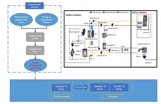
1. Introduction
2. Experimental Setup and Test Method
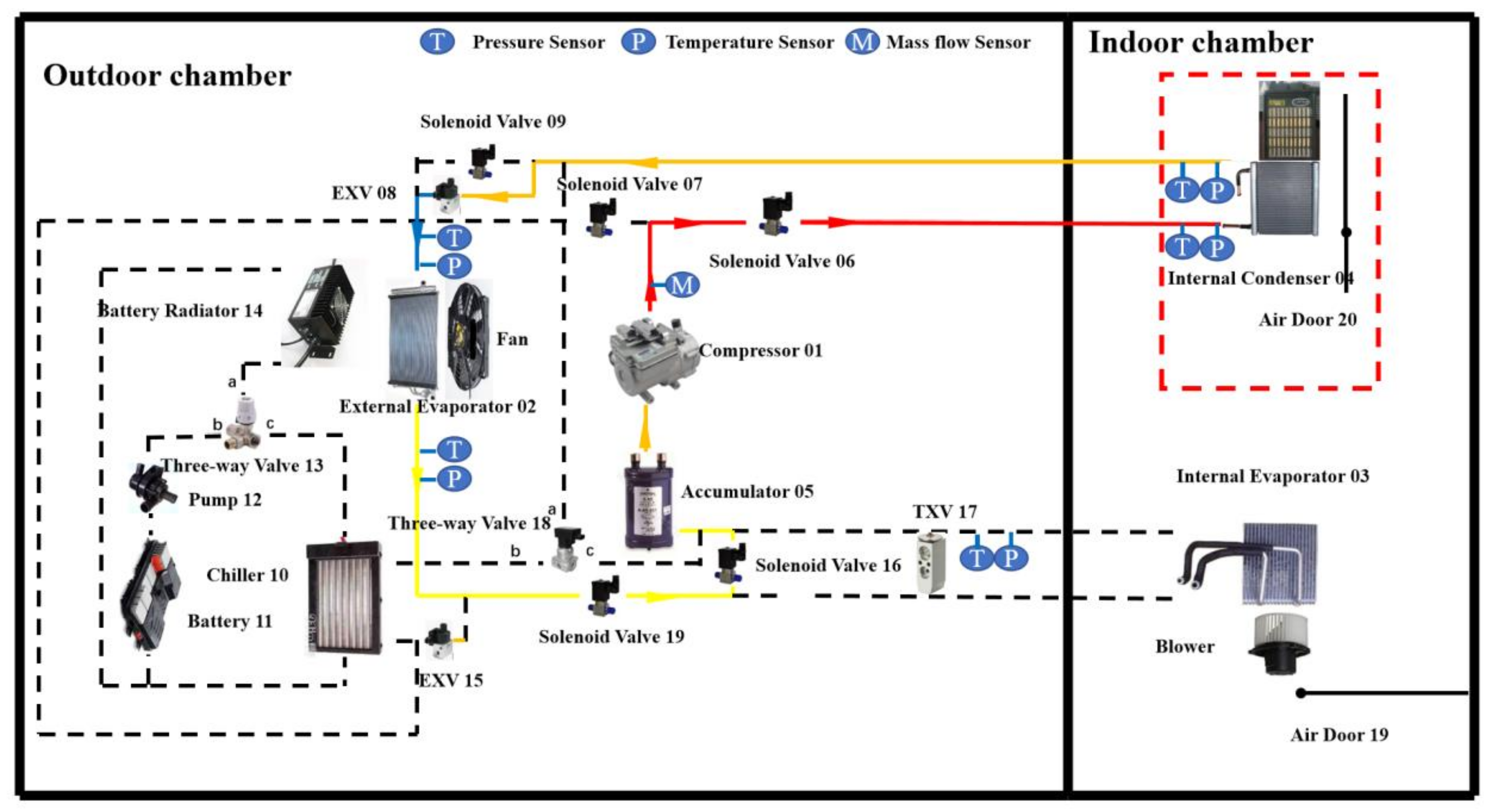
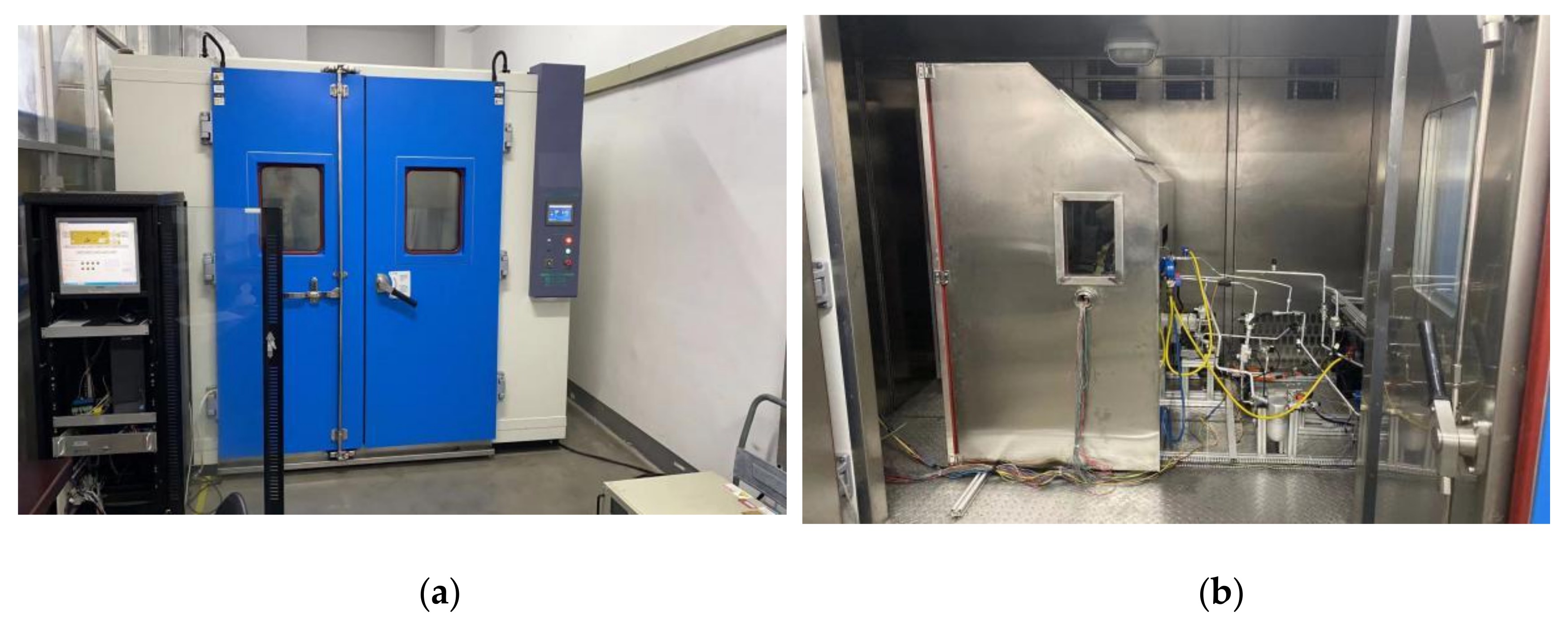
2.1. Experimental Setup
2.2. Experimental Conditions and Mehod
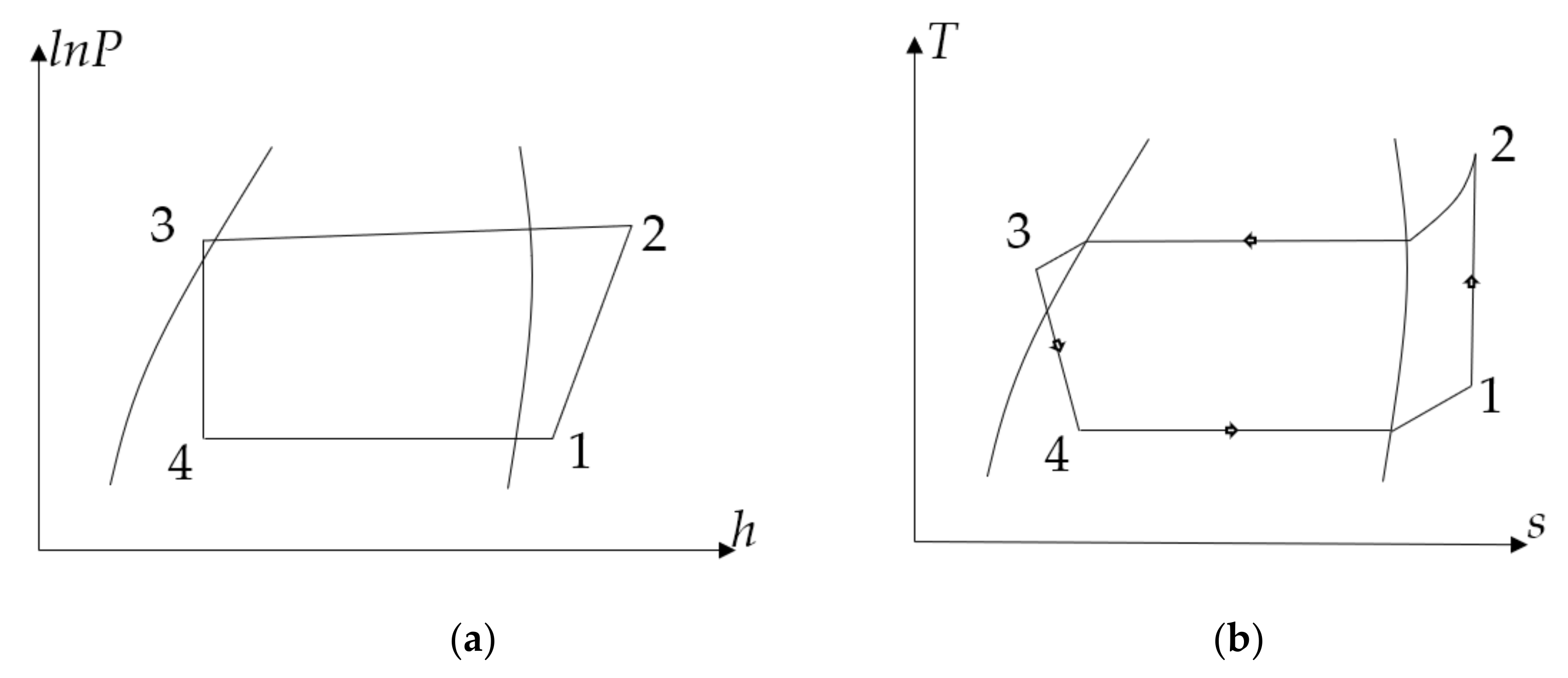
2.3. Exergy Analysis
- The conditions are steady-state.
- The process in the compressor and expansion valve is adiabatic.
- The changes in kinetic energy and potential energy are insignificant.
- (1)
- Compressor exergy losses
- (2)
- Internal evaporator exergy losses
- (3)
- Internal condenser exergy losseswhere is condensing temperature.
- (4)
- Expansion process exergy losses
3. Results and Discussion
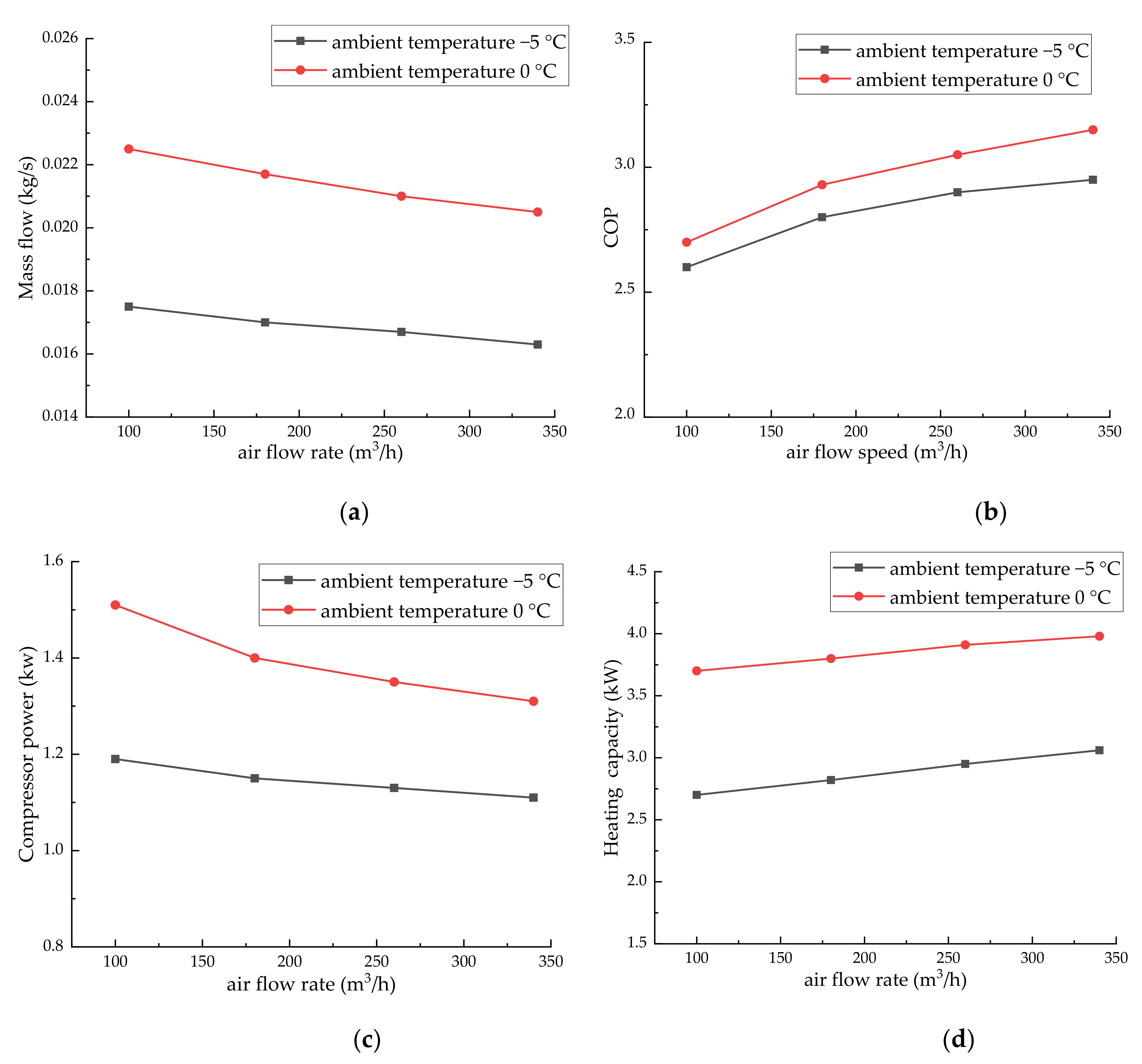
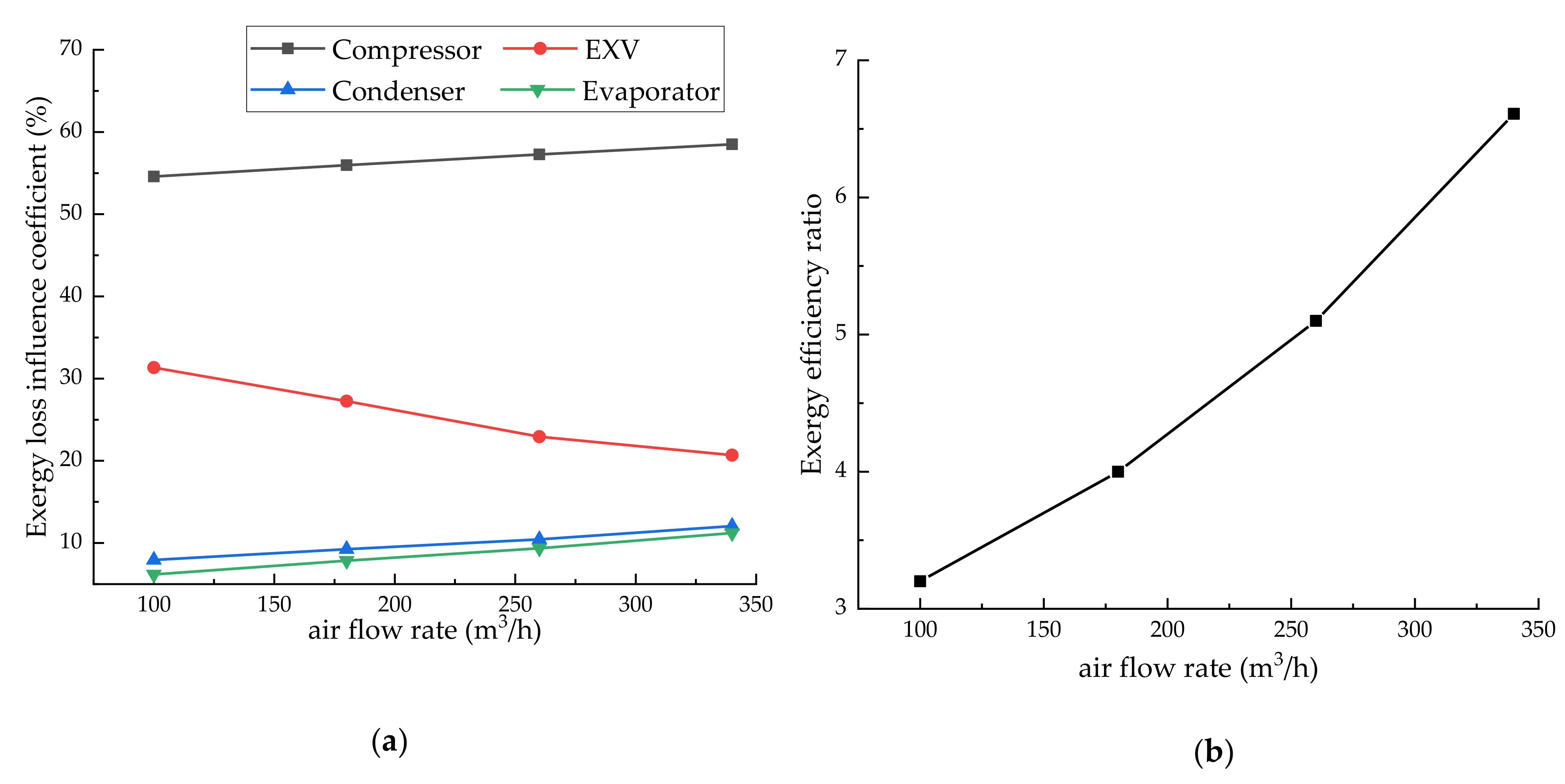
3.1. Effect of Internal Condenser Air Flow Rate
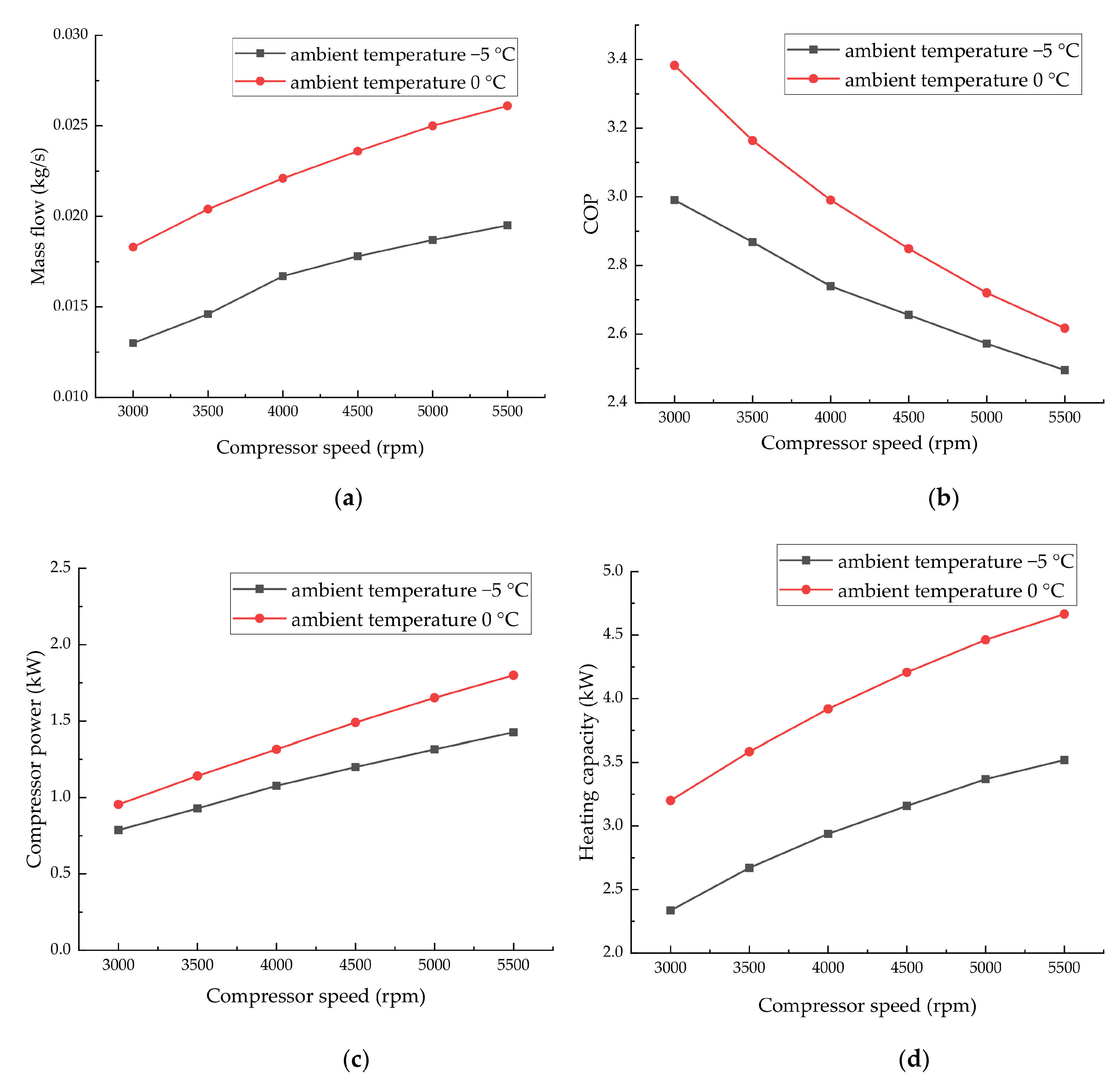
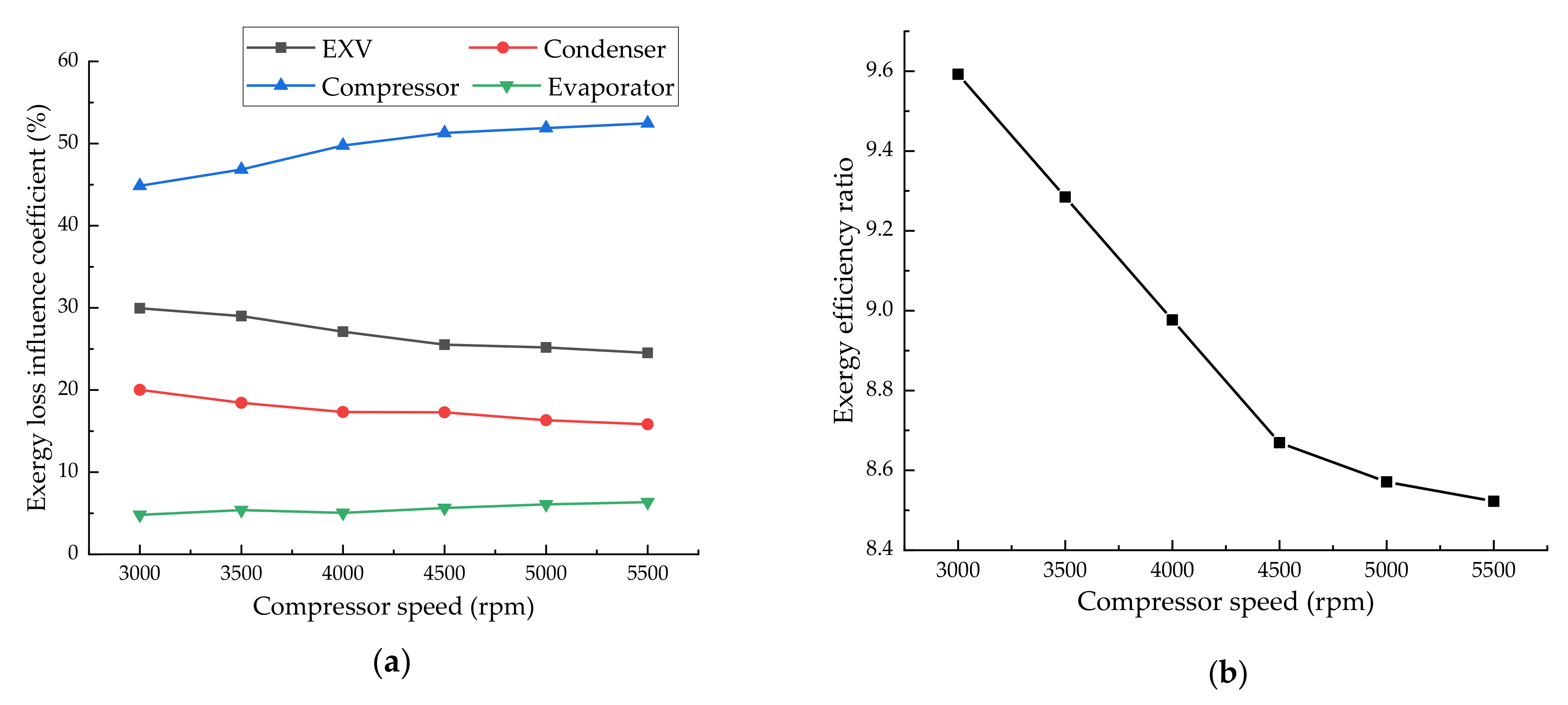
3.2. Effect of Compressor Speed
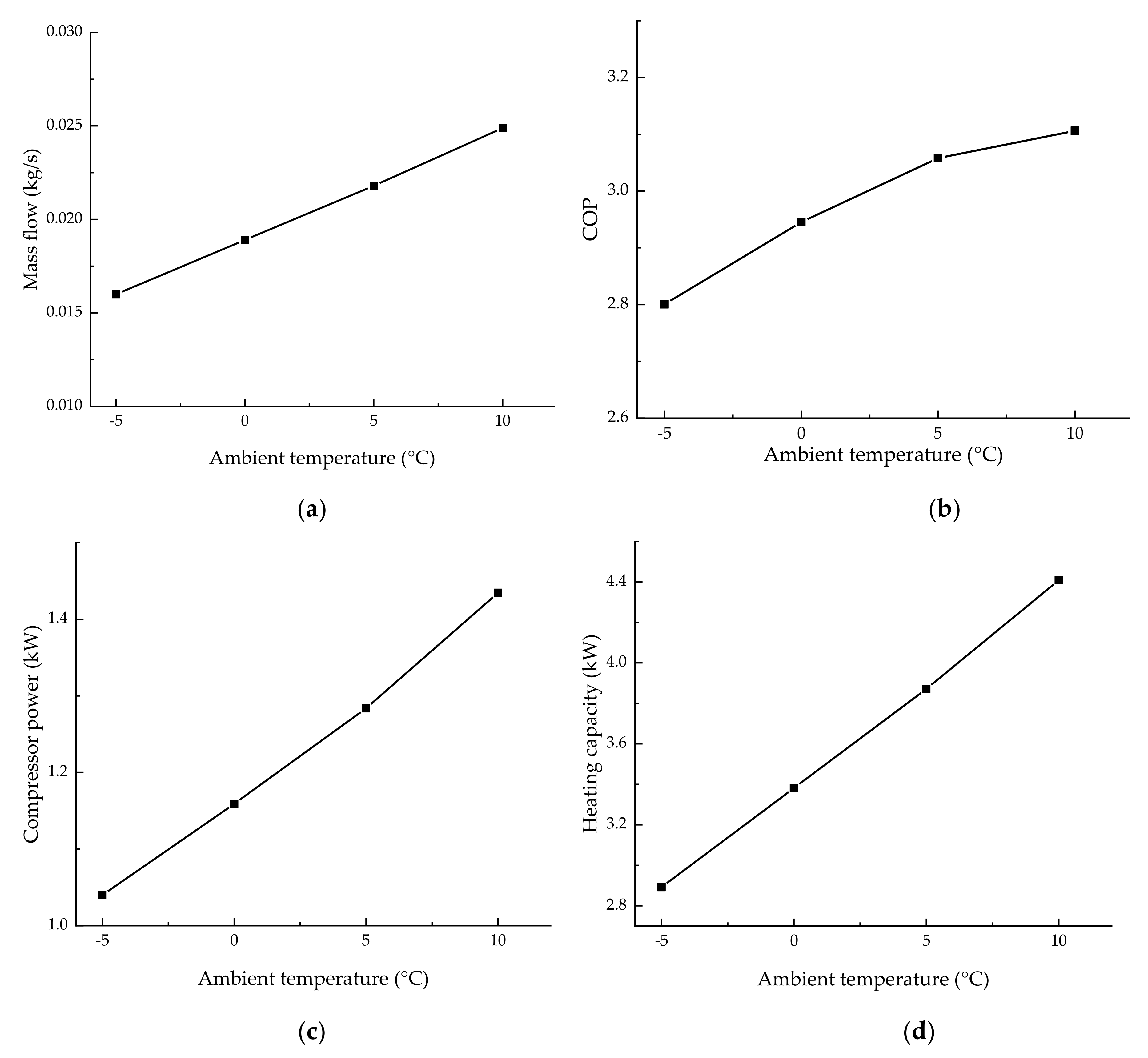
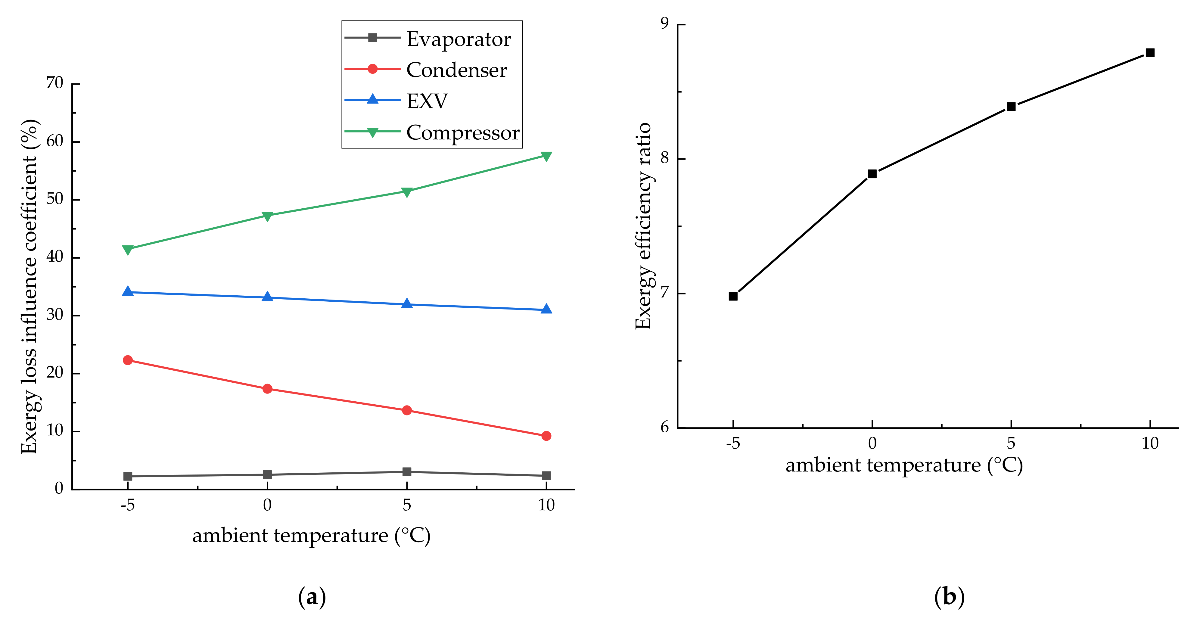
3.3. Effect of Ambient Temperature
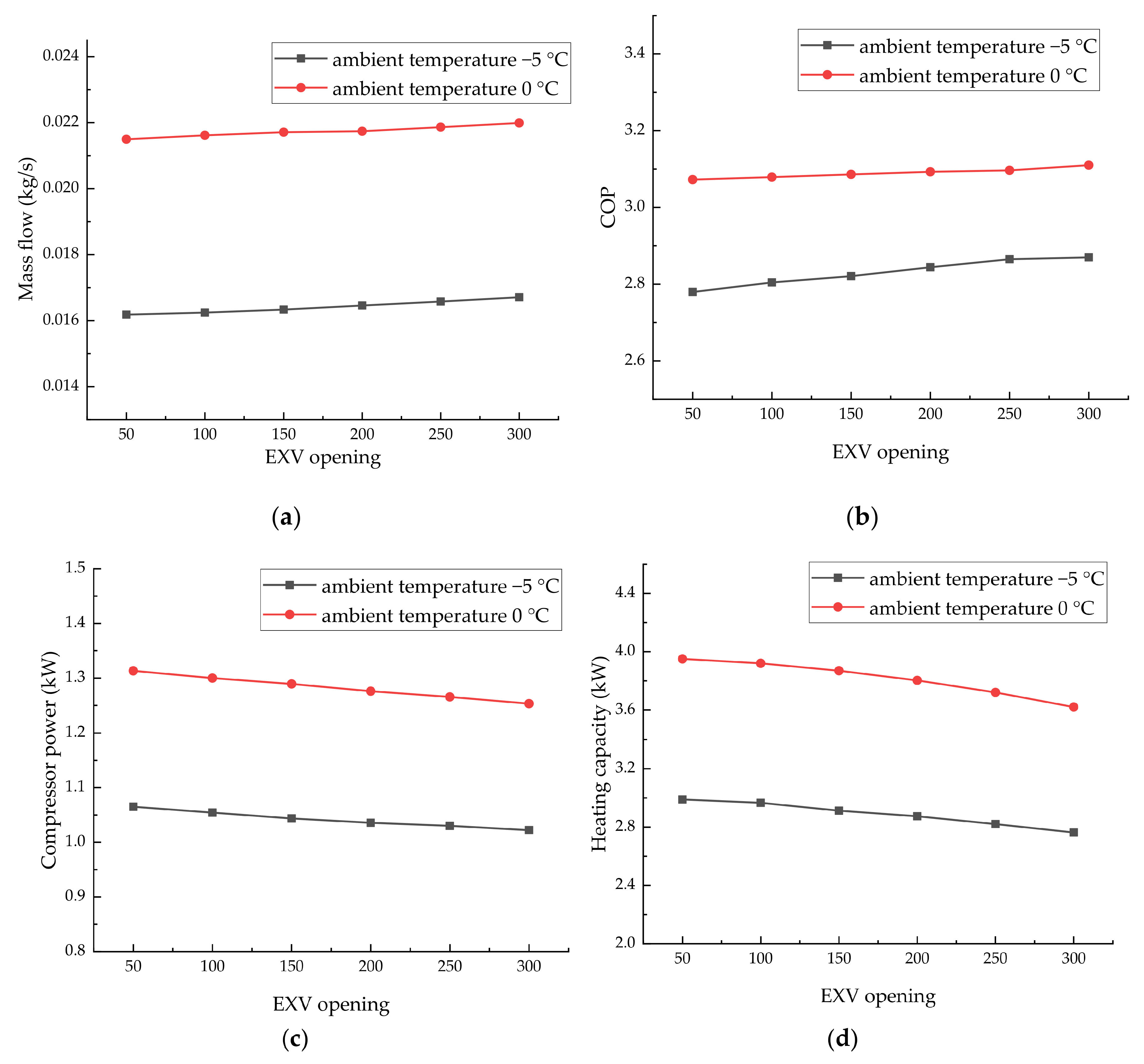
3.4. Effect of EXV Opening
4. Conclusions
Author Contributions
Funding
Conflicts of Interest
Nomenclature
| HPACS | Heat Pump Air Conditioning System |
| COP | Coefficient of Performance |
| BEV | Battery Electric Vehicle |
| EXV | Electrical Expansion Valve |
| TXV | Thermal expansion valve |
| IHX | Internal Heat Exchanger |
| PTC | Positive Temperature Coefficient |
| e | Specific exergy (kJ kg−1) |
| h | Enthalpy (kJ kg−1) |
| s | Entropy (kJ kg−1 K−1) |
| T | Temperature (°C) |
| E | Exergy losses (kJ kg−1) |
| w | Specific work (kJ kg−1) |
| Greek letters | |
| η | Efficiency |
| Subscript | |
| cond | Condenser |
| comp | Compressor |
| eva | Evaporator |
| 0 | Ambient |
| i | Inlet |
| e | Exit |
| val | Expansion Valve |
References
- Granovskii, M.; Dincer, I.; Rosen, M.A. Economic and environmental comparison of conventional, hybrid, electric and hydrogen fuel cell vehicles. J. Power Sources 2006, 159, 1186–1193. [Google Scholar] [CrossRef]
- Yang, F.; Xie, Y.; Deng, Y.; Yuan, C. Predictive modeling of battery degradation and greenhouse gas emissions from U.S. state-level electric vehicle operation. Nat. Commun. 2018, 9, 2429. [Google Scholar] [CrossRef]
- Khayyam, H.; Kouzani, A.Z.; Hu, E.J.; Nahavandi, S. Coordinated energy management of vehicle air conditioning system. Appl. Therm. Eng. 2011, 31, 750–764. [Google Scholar] [CrossRef]
- Higuchi, Y.; Kobayashi, H.; Shan, Z.; Kuwahara, M.; Endo, Y.; Nakajima, Y. Efficient heat pump system for PHEV/BEV. SAE Int. 2017. [Google Scholar] [CrossRef]
- Kumar, V.; Shendge, S.A.; Baskar, S. Underhood thermal simulation of a small passenger vehicle with rear engine compartment to evaluate and enhance radiator performance. SAE World Congr. Exhib. 2010. [Google Scholar] [CrossRef]
- Gao, Q.; Qian, Y.; Fei, G.; Yan, Y. Methodology for thermal analysis of multi-system in engine underhood. Automot. Eng. 2012, 2, 8–15. [Google Scholar] [CrossRef]
- Yuan, X.; Gu, Z.; Yang, Y.; Yuan, Z.; Jiang, L.; Su, W. Numerical simulation on vehicle underhood cooling. Automot. Eng. 2009, 31, 843–847. [Google Scholar] [CrossRef]
- Li, X.; Zhu, L.; Liu, X.; Xiong, F.; Shang, J.; Yang, B. Thermal modeling and sensitivity analysis of a traction motor in a production EV. SAE Tech. Pap. 2019. [Google Scholar] [CrossRef]
- Zhou, G.; Li, H.; Liu, E. Experimental study on combined defrosting performance of heat pump air conditioning system for pure electric vehicle in low temperature. Appl. Therm. Eng. 2017, 116, 677–684. [Google Scholar] [CrossRef]
- Tan, H.; Zhang, X.; Zhang, L.; Tao, T.; Xu, G. Ultrasonic Guided Wave Phased Array Focusing Technology and Its Application to Defrosting Performance Improvement of Air-Source Heat Pumps. Energies 2019, 12, 3117. [Google Scholar] [CrossRef]
- Song, M.; Deng, S.; Dang, C.; Mao, N.; Wang, Z. Review on improvement for air source heat pump units during frosting and defrosting. Appl. Energy 2018, 211, 1150–1170. [Google Scholar] [CrossRef]
- Choi, Y.U.; Kim, M.S.; Kim, G.T.; Kim, M.S. Performance analysis of vapor injection heat pump system for electric vehicle in cold startup condition. Int. J. Refrig. 2017, 80, 24–36. [Google Scholar] [CrossRef]
- Kim, K.Y.; Kim, S.C.; Kim, M.S. Experimental studies on the heating performance of the PTC heater and heat pump combined system in fuel cells and electric vehicles. Int. J. Automot. Technol. 2012, 13, 971–977. [Google Scholar] [CrossRef]
- Hosoz, M.; Direk, M. Performance evaluation of an integrated automotive air conditioning and heat pump system. Energy Convers. Manag. 2006, 47, 545–559. [Google Scholar] [CrossRef]
- Piccolo, A.; Siclari, R.; Rando, F.; Cannistraro, M. Comparative Performance of Thermoacoustic Heat Exchangers with Different Pore Geometries in Oscillatory Flow. Implementation of Experimental Techniques. Appl. Sci. 2017, 7, 784. [Google Scholar] [CrossRef]
- Cao, J.; Chen, C.; Gao, G.; Yang, H.; Su, Y.; Michele, B.; Mauro, C.; Pei, G. Preliminary evaluation of the energy-saving behavior of a novel household refrigerator. J. Renew. Sustain. Energy 2019, 11, 015102. [Google Scholar] [CrossRef]
- Cao, J.; Chen, C.; Hu, M.; Wang, Q.; Mauro, C.; Michael, K.H.L.; Pei, G. Numerical analysis of a novel household refrigerator with controllable loop thermosyphons. Int. J. Refrig. 2019, 104, 134–143. [Google Scholar] [CrossRef]
- Li, W.; Liu, R.; Liu, Y.; Wang, D.; Shi, J.; Chen, J. Performance evaluation of R1234yf heat pump system for an electric vehicle in cold climate. Int. J. Refrig. 2020, 115, 117–125. [Google Scholar] [CrossRef]
- Wu, J.; Zhou, G.; Wang, M. A comprehensive assessment of refrigerants for cabin heating and cooling on electric vehicles. Appl. Therm. Eng. 2020, 174, 115258. [Google Scholar] [CrossRef]
- Peng, X.; Wang, D.; Wang, G.; Yang, Y.; Xiang, S. Numerical investigation on the heating performance of a transcritical CO2 vapor-injection heat pump system. Appl. Therm. Eng. 2020, 166, 114656. [Google Scholar] [CrossRef]
- Wang, D.; Yu, B.; Hu, J.; Chen, L.; Shi, J.; Chen, J. Heating performance characteristics of CO2 heat pump system for electrical vehicle in a cold climate. Int. J. Refrig. 2018, 85, 27–41. [Google Scholar] [CrossRef]
- Wu, D.; Hu, B.; Wang, R. Performance simulation and exergy analysis of a hybrid source heat pump system with low GWP refrigerants. Renew. Energy 2018, 116, 775–785. [Google Scholar] [CrossRef]
- Taslimi Taleghani, S.; Sorin, M.; Poncet, S. Analysis and Optimization of Exergy Flows inside a Transcritical CO2 Ejector for Refrigeration, Air Conditioning and Heat Pump Cycles. Energies 2019, 12, 1686. [Google Scholar] [CrossRef]
- Cho, H.; Park, C. Experimental investigation of performance and exergy analysis of automotive air conditioning systems using refrigerant R1234yf at various compressor speeds. Appl. Therm. Eng. 2016, 101, 30–37. [Google Scholar] [CrossRef]
- Chen, J.; Havtun, H.; Palm, B. Conventional and advanced exergy analysis of an ejector refrigeration System. Appl. Energy 2015, 14, 139–151. [Google Scholar] [CrossRef]
- Chen, J.; Havtun, H.; Palm, B. Investigation of ejectors in refrigeration system: Optimum performance evaluation and ejector area ratios perspectives. Appl. Therm. Eng. 2014, 64, 182–191. [Google Scholar] [CrossRef]
- Shen, M.; Gao, Q.; Wang, Y.; Zhang, T. Design and analysis of battery thermal management system for electric vehicle. J. Zhejiang Univ. 2019, 53, 1398–1406. [Google Scholar] [CrossRef]


| Measurement Parameter | Sensor Type | Range | Precision |
|---|---|---|---|
| Temperature/°C | Omega temperature sensor | −50–200 | ±0.1 |
| Pressure/kPa | Omega pressure sensor | 0–4000 | ±5 |
| Mass flow rate (kg/h) | Micromotion mass flow meter | 0–200 | ±0.5 |
| Ambient Temperature (°C) | Compressor Speed (rpm) | Air Flow Rate of the Internal Condenser (m3/h) | Expansion Valve Opening |
|---|---|---|---|
| 10 | 3000–5500 | 100–340 | 50–300 |
| 5 | 3000–5500 | 100–340 | 50–300 |
| 0 | 3000–5500 | 100–340 | 50–300 |
| −5 | 3000–5500 | 100–340 | 50–300 |
© 2020 by the authors. Licensee MDPI, Basel, Switzerland. This article is an open access article distributed under the terms and conditions of the Creative Commons Attribution (CC BY) license (http://creativecommons.org/licenses/by/4.0/).
Share and Cite
Tang, X.; Guo, Q.; Li, M.; Jiang, M. Heating Performance Characteristics of an Electric Vehicle Heat Pump Air Conditioning System Based on Exergy Analysis. Energies 2020, 13, 2868. https://doi.org/10.3390/en13112868
Tang X, Guo Q, Li M, Jiang M. Heating Performance Characteristics of an Electric Vehicle Heat Pump Air Conditioning System Based on Exergy Analysis. Energies. 2020; 13(11):2868. https://doi.org/10.3390/en13112868
Chicago/Turabian StyleTang, Xingwang, Qin Guo, Ming Li, and Mingzhe Jiang. 2020. "Heating Performance Characteristics of an Electric Vehicle Heat Pump Air Conditioning System Based on Exergy Analysis" Energies 13, no. 11: 2868. https://doi.org/10.3390/en13112868
APA StyleTang, X., Guo, Q., Li, M., & Jiang, M. (2020). Heating Performance Characteristics of an Electric Vehicle Heat Pump Air Conditioning System Based on Exergy Analysis. Energies, 13(11), 2868. https://doi.org/10.3390/en13112868