1. Introduction
The nickel-rich cathode materials of lithium-ion battery such as LiNi
0.815Co
0.15Al
0.035O
2 (NCA) have been chosen for electric vehicular application due to their high energy density and power density [
1,
2]. Higher Ni content and lower cobalt content of NCA increase the capacity of the layered cathode material. While doing so, the price of the cathode material is decreased which is favorable towards future developments [
3,
4]. In addition, lowering cobalt content is also environmentally beneficial.
Current technologies for mass production of NCA are co-precipitation [
5,
6] and the solid-state method [
7,
8,
9]. Moreover, extensive investigations have also been reported to obtain NCA with good characteristics [
10,
11]. The main challenge of these synthesis method is a long processing time of both precursor synthesis and heating process, e.g., sintering or calcination [
12,
13]. Also, a large amount of wastewater containing hazardous and non-degradable chemicals is another problem [
14]. To overcome these problems, a new approach of processing technology, which is fast and produces minimum waste, is in high demand [
15].
Herein, we investigate the production of NCA (LiNi
0.815Co
0.15Al
0.035O
2) via flame assisted spray pyrolysis (FSP/FASP) method. By this technique, annealing treatment to intercalate lithium ion into NCA matrix can be done in short period of time, however, the implementation of the FASP method to obtain NCA was seldom reported. Zhang et al. produce NCA via FASP using a non-aqueous solution of Li-Ni-Co-Al. Previously, we performed FASP using citric acid as the fuel, which greatly affected the powder product [
16]. A brief summary of previous NCA preparation techniques is listed in
Table 1. In this research, our proposed technique used only water as the solvent and urea as the fuel additive without any expensive chemicals. Thus, this process is environmentally friendly, with less production cost, due to the absence of additional expensive chemicals and less energy for annealing. The prepared NCA materials were tested in full cell lithium-ion battery using the 18,650-type cylindrical cell format. This test was done to measure the specific charge—discharge capacity, cycleability, and rateability of lithium-ion battery in the commercial application.
2. Materials and Methods
Schematic diagram of flame-assisted spray pyrolysis is presented in
Figure 1. A stoichiometric amount of nickel nitrate hexahydrate (Ni(NO
3)
2·6H
2O, Merck), cobalt nitrate hexahydrate (Co(NO
3)
2·6H
2O, Merck) and aluminum nitrate nonahydrate (Al(NO
3)
3·9H
2O, Merck) were mixed in distilled water or aquadest using magnetic stirrer for an hour to make sure all of the component were thoroughly dissolved. After a stable solution was obtained, 60 mg/mL of urea (CO(NH
2)
2, Merck) was added to the solution. The overall metal concentration in the solution was 1 M and then the solution was injected to a liquid nozzle (MLR-ABS13B) via a syringe pump with the rate of 0.5 mL per minute. The airflow rate was tightly maintained at 4 L per hour and the fuel (LPG, PERTAMINA) rate was 1 L per hour. The obtained particles, labelled as ternary metal oxides (TMO), were dried in oven for an hour and mixed with lithium hydroxide monohydrate (LiOH·H
2O Merck) with the ratio of Li/NCA: 1.05/1 using mortar and pestle for an hour. Then, 5 mol% of excess LiOH·H
2O was added to avoid final lithium deficiency caused by lithium evaporation throughout high temperature sintering. The TMO/LiOH mixture was fired in a previously purged box furnace at varying temperatures for 10 h under O
2 flow with the heating rate of 10 °C/min.
Thermal gravimetric and differential scanning calorimetry (TG-DSC) was performed to analyze the thermochemical properties of ternary metal oxide and sintering behavior of ternary metal oxide lithiation. X-ray diffraction patterns of obtained NCA samples were investigated by X-ray Diffractometer (D2 Phaser Bruker, Karlsruhe, Germany) using CuK-α radiation (wavelength: 1.5406 A) in the range of 10° ≤ 2θ ≤ 80° the NCA particle morphology was examined using a Scanning Electron Microscope (JEOL JSM-6510LA, Akishima, Japan). The surface chemistry of the TMO and ultimate NCA product were examined using Fourier Transformed Infra-Red (FTIR) spectroscope (Shimadzu FTIR spectrometer, Kyoto, Japan). The elemental composition of NCA product was analyzed using Energy Dispersive Spectroscopy (EDS) (Oxford Instrument, Abingdon, UK).
The electrochemical characterization of as-obtained NCA cathode material was measured in an 18,650 type cylindrical full cell whereas artificial graphite (MTI, California, CA, USA) was employed as the anode. The as prepared NCA electrode was carefully designed as the limiting reactant; thus, the final weight of NCA in the cell was referred as the weight basis for specific capacity calculation (Theoretical Anode capacity/cathode capacity > 1). NCA electrode sheet was made by dispersing 80%w/w of NCA samples with 10%w/w of acetylene black(AB) and 10%w/w of poly(vinylidene fluoride) PVDF binder in N-Methyl-2-pyrrolidone (NMP) to obtain a homogenous slurry which then coated on both sides of Aluminum (Al) foil using doctor blade technique. The cathode sheet was dried and kept under vacuum at 120 °C. Using the same technique, the counter anode was fabricated by dispersing mesocarbon microbeads (MCMB) artificial graphite, AB, carboxy-methyl cellulose or CMC (MTI, California, CA, USA) and Styrene Butadiene Rubber (SBR) (Gelon, Linyi, China) with the ratio of MCMB:CB:CMC:SBR = 90:3:2:5 in distilled water as solvent followed by coating process of anode slurry on both sides of copper (Cu) foil. and the anode sheet was dried in vacuum oven for a day. The cathode and anode were calendared using rotary pressing machine (MSK-HRP-01, MTI) and cut into desired dimension. The final mass loading and thickness of the cathode is ~23 mg/cm2 and 120 µm while the mass loading and thickness of the anode is ~21 mg/cm2 and 100 µm, respectively. A nickel and an aluminum strips were welded on the edge of the anode and cathode sheet, respectively. An anode sheet, polypropylene separator (MTI, California, CA, USA) and a cathode sheet were rolled. The Ni strip was welded to the bottom of the cylindrical case while the Al strip was welded to the upper cap. The fabricated cells were kept in a vacuum oven to minimize the moisture content. The cells were filled with 1 M LiPF6 dissolved in ethyl carbonate (EC) and di-methyl carbonate (DMC) mixture (1:1, v/v) electrolyte. The electrolyte filling was performed inside a glovebox (O2 < 1 ppm and H2O < 1 ppm). Each cell was allowed to be aged for 24 h before the charge—discharge was conducted. The specific charge—discharge capacity was measured using NEWARE cylindrical cell analyzer and BTS data analysis with working voltage of 2.7–4.3 V. During the formation phase, the rate of charge and discharge was 0.1 C (1C theoretical = 200 mA/g) and cycled for 5 times. After the formation phase, the cell was cycled at 0.2 C for 50 cycles and rated at elevating discharge rates, i.e., (0.5 C, 1 C, and 2 C). To assure the reliability of data, each samples was assembled into 3 cells.
3. Results and Discussion
To investigate the thermochemical property and annealing behavior, a TG-DSC test was conducted.
Figure 2 exhibits the thermochemical properties of as-prepared metal oxide from FASP method and its lithiation behavior during sintering step.
Figure 2a shows the TG-DSC curve of as-prepared metal oxide by FASP. An asymptotic curve of TG indicates weight loss occurrence at 35–300 °C. Based on previous studies [
20], this weight loss due to stepwise melting and decomposition of H
2O and NO
3. It is found that the weight loss is only ~8% which indicate that only small amount of metal nitrate was unreacted during the FASP process. In majority, metal nitrates were successfully decomposed into their oxide forms which consistent with the stable curve at >320 °C. The decreasing of DSC curve at 700 °C could be attributed to the partial reduction of Ni from Ni
2O
3 to NiO.
Figure 2b displays the thermal analysis curve of the ternary metal oxide lithiation process at 30–900 °C under flowing air. It is shown that 17% of weight loss undergone at the temperature 35–400 °C. This can be assigned to the decomposition of residual nitrates and the removal of water from absorbed water molecule and LiOH·H
2O water crystal, which is consistent with the presence of strong endothermic peak at 108 °C. Double endothermic peaks were detected at 410 and 456 °C due to endothermic melting of LiOH and LiOH bonding to the ternary metal oxide forming a quasi-NCA compound. At temperatures of 420–650 °C, a weight loss of 7% occurred. It can be assumed that a dihydroxylation process of LiOH happens and releasing water molecule. Small exothermic peak is observed at 613 °C indicates an exothermic partial oxidation of Ni from NiO to Ni
2O
3 [
21], but is followed by reduction of Ni
2O
3 to NiO at higher temperature (> 700 °C) which shows that the presence of O
2 atmosphere is pivotal at this temperature. Based on TG profile, there is no weight loss at the temperature of 700–900 °C.
3.1. FTIR Studies
FTIR Spectra of as-obtained ternary metal oxides is depicted in
Figure 3. A broad peak located around ~3440 cm
−1 is strongly corresponds to the presence of absorbed water in the powders. Both sharp peaks located at ~1500 cm
−1 and ~1383 cm
−1 can be attributed to streching vibration of N-O while a peak located at ~1430 is corespond to the complex NO or nitrosamines species. A sharp peak observed at ~867 cm
−1 is attributed to CO
32−. The presence of these species demonstrates that during the flame-assisted spray pyrolysis process, NO
3− and urea were not completely and thoroughly decomposed into gaseous matters which confirms the thermochemical analysis result. Therefore, to obtain pure ternary metal oxides from such method, a further heat treatment step is highly recommended. Complete decomposition of these residual species occurred during the high temperature lithiation process.
Figure 4 displays the FTIR spectra of NCA samples sintered at 480 °C, 600 °C, 720 °C, 800 °C and 840 °C which labelled as NCAT1, NCAT2, NCAT3, NCAT4 and NCAT5, respectively. Beside metal-oxygen or M-O bond detected at wavelength ~645 cm
−1, OH
− species are detected in NCAT1 sample which correspond to the unreacted LiOH. Physically, NCAT1 sample has hygroscopic properties. This phenomenon confirms the TG/DSC analysis where at 480 °C, the LiOH just started to melt and incorporate into the ternary metal oxide structure, however, LiNi
0.815Co
0.15Al
0.035O
2 has not been formed. With higher sintering temperature, the OH
− peaks disappeared while carbonate species can be observed easily. The carbonate species detected at 1400–1600 cm
−1 can be assigned to the unreacted excess of LiOH. The residual Li on the surface will form a LiOH after sintered. However, when exposed to atmosphere, the LiOH layer will react with CO
2 forming Li
2CO
3 [
6,
22]. With increasing temperature, the Li
2CO
3 content is decreasing. CO
32− and OH
− species are vaguely detected based on NCAT5 spectra as a result of Li loss due to evaporation at high temperature. The presence of Li
2CO
3 in every sample is considered neglegible and be left unprocessed [
23].
3.2. Structural Analysis
Ternary Metal Oxide Structural Characterization
Figure 5 presents the XRD patterns of ternary metal oxide obtained from flame-assisted spray pyrolysis of 1 M ternary metal salt solution. It is clearly seen that all of the peaks are well indexed to the NiO Reference (Joint Committee on Powder Diffraction Standards (JCPDS) Card NiO #44-1159). The flame-assisted spray pyrolysis is successfully decomposing metal nitrates into their oxide form. No observable impurity in the diffraction pattern confirms the previous TG-DSC analysis. The sharp peaks indicate that the powder has crystalline structure. Since the prepared powder exhibits good structural characteristics and the metal nitrates are highly soluble in water, the concentration of the precursor solution was then varied at 0.5, 1, 1.5, and 2 M. The XRD patterns of ternary metal oxides using different precursor concentration solution are displayed in
Figure 6. At precursor concentration of 1.5 and 2 M, the diffraction patterns are matched with the reference card. However, at lower precursor solution concentration of 0.5 M, boarder peaks and impurities peaks could clearly observable hence it is concluded that the within the range of 0.5 to 4 M, the peaks are sharper as the concentration increased. The presence of urea and large ammount of NO
3− species promotes the decomposition of metal nitrates into metal oxides. Lower nitrate concentration results in unfinished pyrolisis reaction as there were more water to be evaporated while less heat is used to decompose the metal.
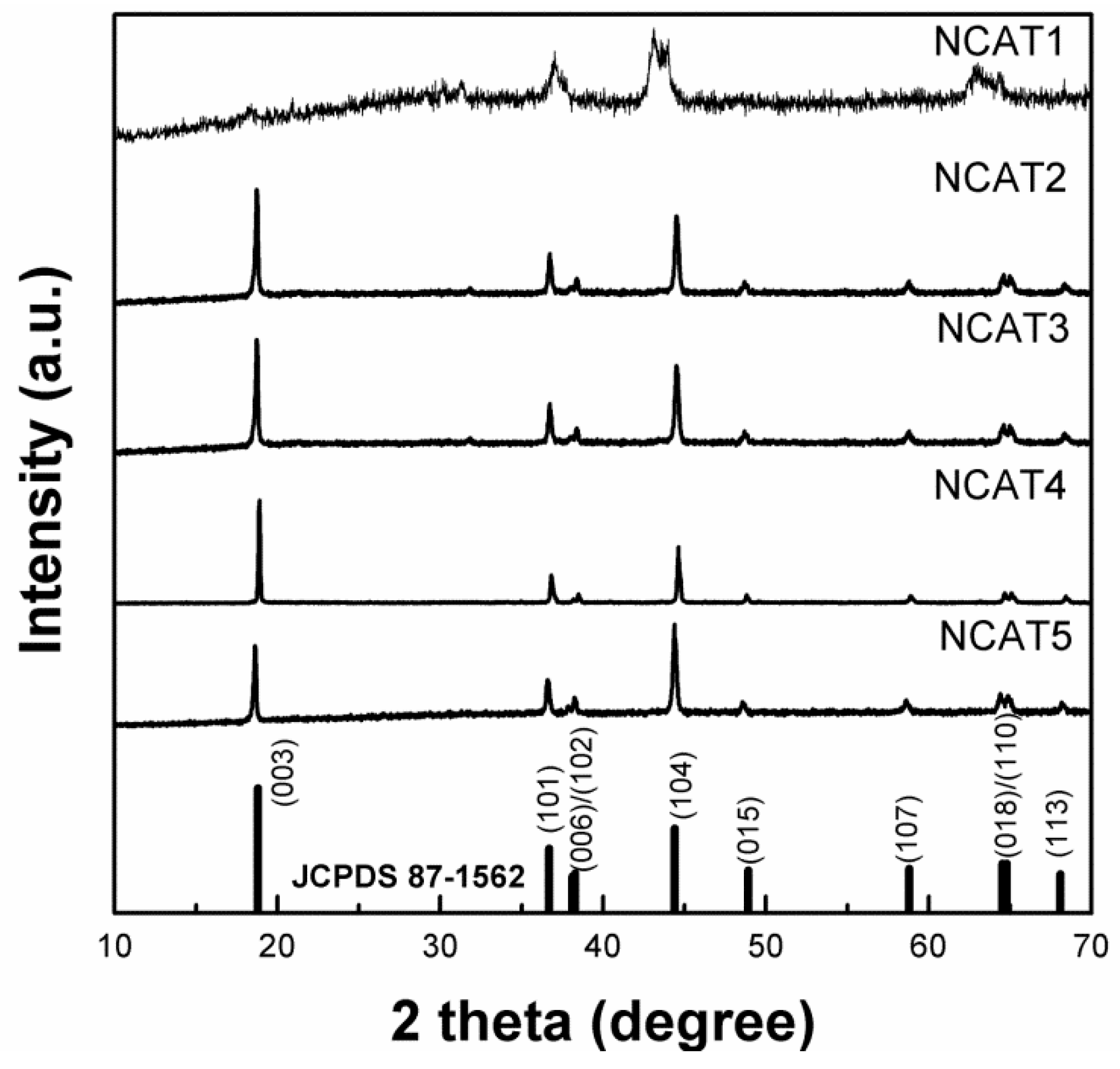
Figure 7 shows the XRD patterns of NCA particles sintered for 10 h under different temperature of sintering which is 480 °C, 600 °C, 720 °C, 800 °C, and 840 °C labeled as NCAT1, NCAT2, NCAT3, NCAT4, and NCAT5, respectively. All XRD patterns are well-indexed with the JCPDS cards 87-1562 which indicates α-NaFeO
2-like crystal structure with no impurities detected except NCAT1 samples. The NCAT1 sample doesn’t resemblance such characteristic due to unfinished decomposition of lithium hydroxide (LiOH) and unfinished phase formation of layered LiNi
0.815Co
0.15Al
0.035O
2 [
24]. According to Kalyani and Kalaiselvi, at the temperature of ≈400 °C, the NiO and Li
2O were formed but the substitution of Li
+ to Ni
2+ and lithiation process starting to occur at the temperature of 600 °C and above hence the formation of peak (003) and other peaks at the temperature ≥ 600 °C (sample NCAT2, NCAT3, NCAT4, and NCAT5). All samples, except NCAT1, have a clear double splitting of (006)/(102) and (018)/(110) which indicates the particle exhibits excellent ordering of Li and Ni/Co distribution in a hexagonal layered structure and excellent electrochemical characteristics [
25].
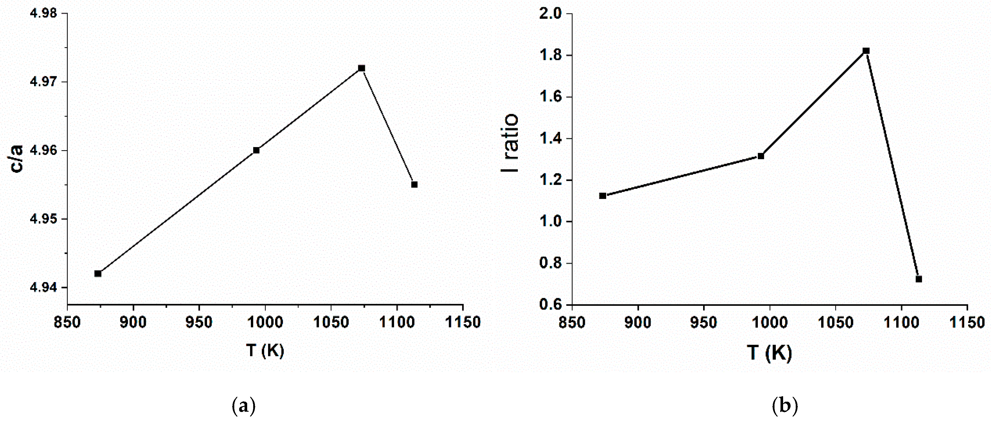
Table 2 shows a lattice parameter analysis of post treated materials sintered at various temperature calculated by least squares method. Based on
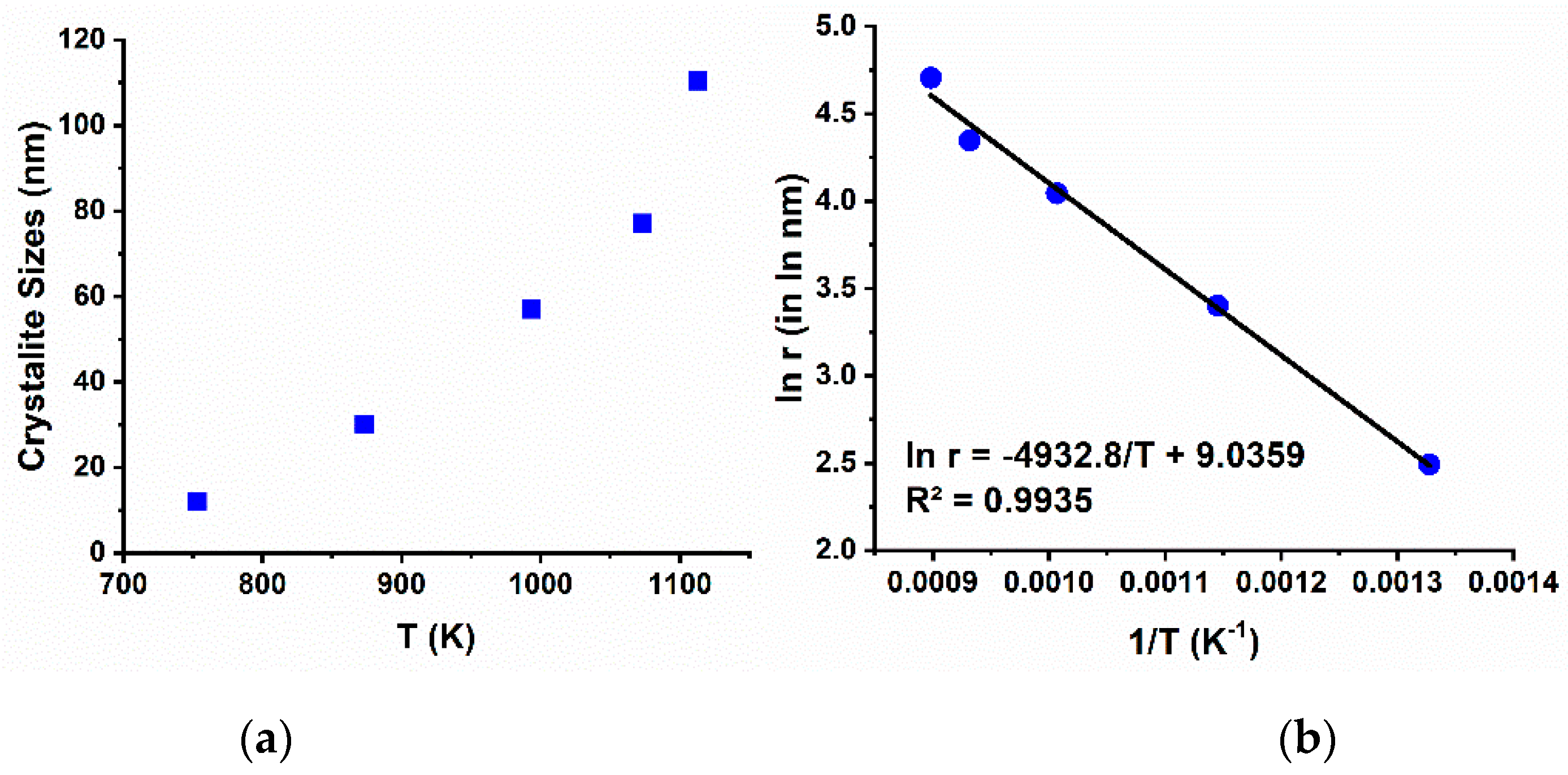
Figure 8a, it is clearly shown that the increase of sintering temperature result in the increasing value of c/a from 480 to 800 °C but decreased at the temperature of 840 °C. The presence of Ni
2+ which formed during the sintering process brings negative impact towards electrochemical performance of NCA as a cathode material. Similar Ni
2+ radii with Li atomic radii can cause substitution of Li with Ni
2+. Stable Ni
2+ ion, which is difficult to be oxidized, will form a blockade in Li ions’ pathway, hence the insertion and extraction of Li-ions are hampered. This occurance will cause a poor electrochemical performance and rapid capacity decay. The substitution of Li ion with Ni (II) ion is often called cation mixing which its degree or level could be determined by calculating the intensity ratio (I ratio) of peak (003) and peak (104) or I(003)/I(104).
Figure 8b shows the I ratio value are increased as the temperature increased from 480 °C to 800 °C but decreased at the temperature of 840 °C making both c/a and I ratio have similar trends at various sintering temperature. The decrease of I ratio at 840 °C is mainly caused by the partial evaporation of Li at higher temperature which easily reduce Ni
3+ to Ni
2+ to balance the oxidation state of NCA. From
Table 2, the NCAT4 samples has the highest I ratio value of 1.822. Based on previous studies, if the I ratio is larger than 1.2, the cation mixing level is low hence the layer structured cathode material will have excellent electrochemical properties [
9,
21,
26].
Evaluated using the Debye-Scherrer’s formula (Equation (1)) [
27,
28], the crystallite sizes (Dx) of the NCA samples prepared at various temperature, can be seen in
Table 3 and presented in
Figure 8a. It is clearly seen that the crystallite size increases exponentially as the sintering temperature elevate.
where
K,
λ, and full-width at half maximum (FWHM) represent shape factor (=1), CuK-α radiation wavelength (=1.5406 Ǻ), and full-width at half maximum, respectively. Activation energy (Ea) of metal oxide particle can be evaluate using Equation (2).
where, ‘
r’ and ‘
k’ are the symbol of particle crystallite size prepared at absolute sintering temperature ‘
T’ and Boltzmann’s constant (8.617 × 10
−2 meV/K), respectively. Based on
Figure 9b, the activation energy of NCA formation from the reaction between TMO and LiOH·H
2O is calculated to be 425 meV [
29].
Figure 10 shows the XRD patterns of the NCA samples sintered at 800 °C for 10 h with varying precursor solution concentration where the ternary metal oxide products are displayed in
Figure 6. The NCA samples prepared using concentration of 0.5, 1.0, 1.5, and 2.0 M are labelled as NCAM1, NCAM2, NCAM3, and NCAM4, respectively. Based on the XRD patterns depicted in
Figure 10, all sample peaks are well matched to the α-NaFeO
2 structure with space groups of R_3m [
30,
31]. Structural parameter of c/a and I ratio are listed in
Table 4. It is noticed that as the precursor solution increased, both c/a and I ratio values are increased then start to decrease at 1 M mark. Therefore, the optimum precursor solution concentration is established at 1 M [
32]. Although the increasing of the precursor solution concentration is followed by increasing nitrate ions, a larger particle is generated by using higher concentration. Since the particles are larger, the Ni oxidation process under oxygen-rich atmosphere would be hindered, thus the sample has higher Ni
2+ content and poor structural properties. The formation of crystal is also hindered based on the crystallite size data listed in
Table 4.
3.3. SEM Studies
Figure 11 presents the SEM images of as-prepared NCA samples using variations of precursor solution concentrations and sintering temperature of 800 °C for 10 h. As it can be seen, at low concentration of 0.5 M, loose submicron-sized polyhedron-shaped particles (less than 1 μm) can be clearly observed. At 1 M, quasi-sphericle micron-sized particles (less than 4.6 μm) was formed. As the concentration of precursor solution increased till 2.0 M, the loose particles agglomerate into iregular-shaped large particles around 25 μm agglomerate size. It is predicted that the agglomeration is not only promoted by high concentration of precursor solution, but also due to high temperature sintering of the ternary oxide. The electrocehemical performance of Ni-rich cathodes are highly sensitive toward undesirable side-reactions between the electrolyte and Ni-rich cathode which is promoted by large surface area of the particles. However, small surface area can hamper the diffusion of Li-ions during the insertion and de-insertion of Li ions resulting in a poor rate performance of the battery.
3.4. Electrochemical Performance
The electrochemical performance of each sample was tested using full-cell battery where microbeads of graphite were utilized as the anode. Full cell assembly test results give strong evidence regarding the electrochemical property of the samples, however, full cell test was scarcely reported in previous studies [
33,
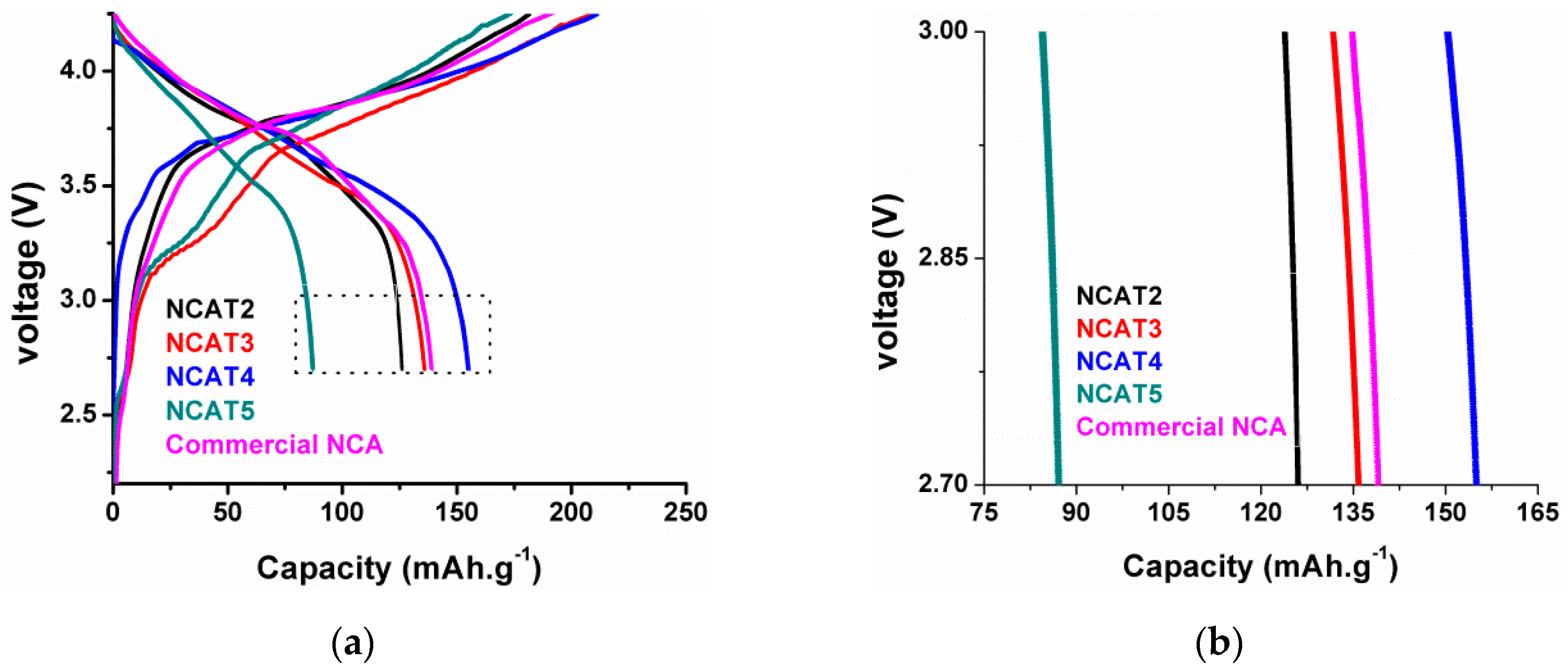
34]. In this study, instead of using coin cells or pouch cells, the NCA samples electrochemical test were conducted in an -type cylindrical cell. Commercial NCA/Graphite battery was carefully assembled using the same technique and the electrochemical performance test results were compared with each sample test results. The charge—discharge curves obtained at 1/10 C (20 mA·g
−1) of each sample and commercial NCA are shown in
Figure 12a. It is noticed that sample NCAT4 has better specific discharge capacity than commercial NCA while NCAT3 has comparable specific discharge capacity to commercial NCA. The NCAT2 has lower specific discharge capacity than commercial NCA while NCAT5 is too low compared to commercial NCA. These phenomena are in good agreement with previous characterization results, especially the XRD analysis results. The trend of initial specific charge–discharge capacity and coulombic efficiency follows the trend of structural analysis presented in
Figure 7 thus indicating the sintering temperature affects the electrochemical performance of the as-prepared NCA sample, especially during the formation phase of the battery cell.
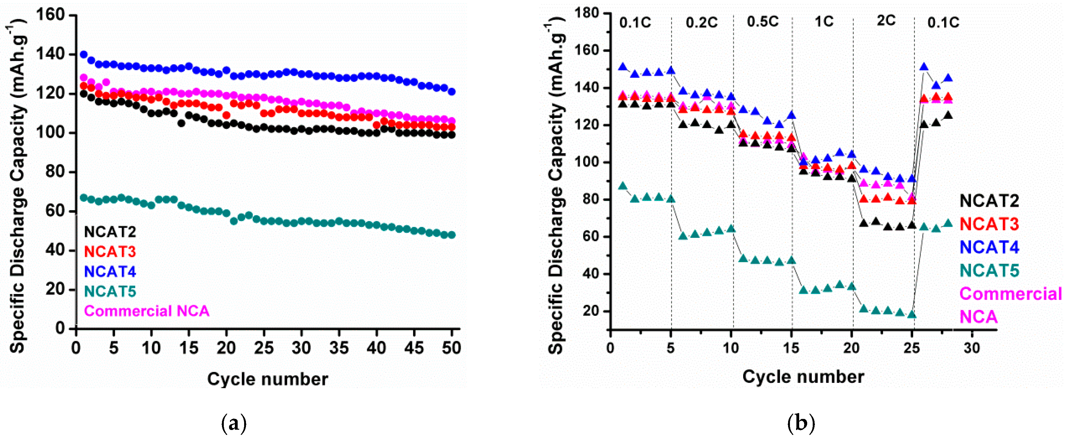
The cycle performance of the samples is performed at 0.2 C (40 mA·g
−1) and depicted in
Figure 13a. After 50 cycles, sample NCAT4 still exhibits the highest capacity retention of 92%, while NCAT2, NCAT3, and NCAT5 have capacity retention of 85%, 86%, and 82%, respectively. A stable cycle performance of NCAT4 is attributed to the low cation mixing level of the material and good hexagonal layer structure.
Figure 13b displays a comparison of the specific discharge capacity of each cylinder cells at rates of 0.1, 0.2, 0.5, 1.0, and 2 C, whereas each cell was charged using current density of 0.5 C (100 mAh·g
−1) before discharge at various rates. It can be seen that NCAT4 still delivered a capacity of ~100 mAh·g
−1 using 2 C rate while NCAT5 exhibits poor discharge capacity which is under 20 mAh·g
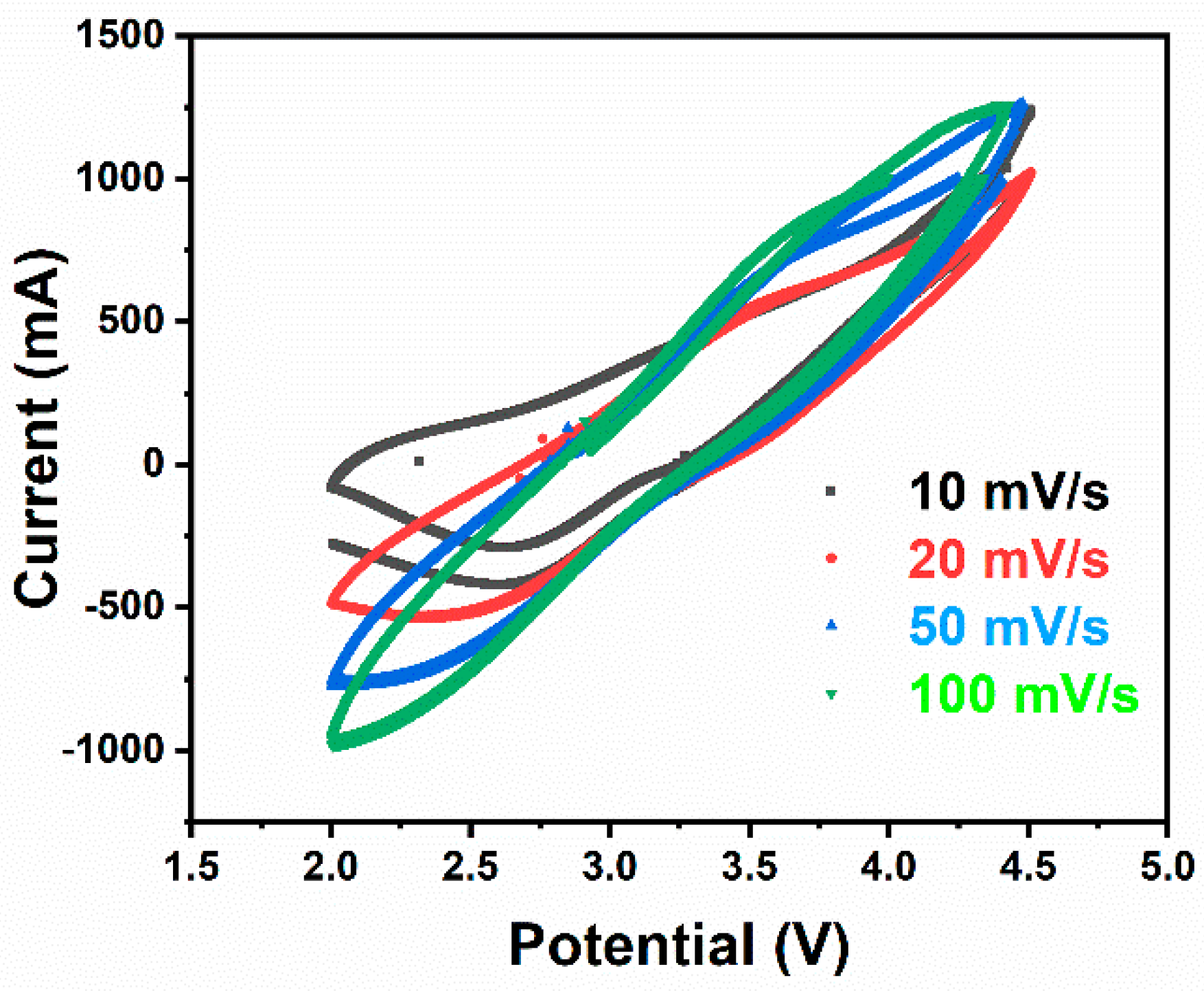
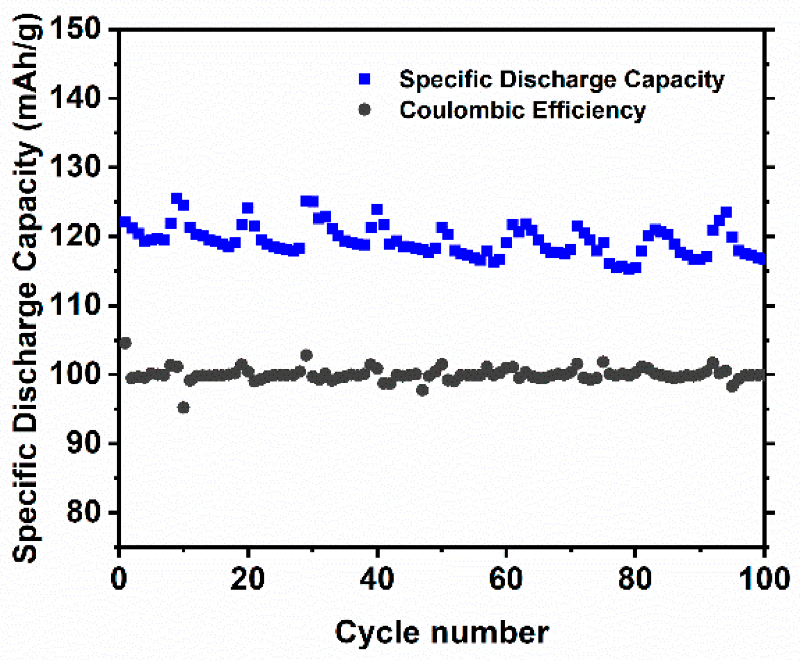
−1. This phenomenon confirms previous prediction where partial evaporation of Li and reduction of Ni occurred during high sintering temperature employed at NCAT5 sample. A stable discharge capacity can be received in each cells when the discharge rate was set to 0.1 C again, thus proving a good reversibility of the materials. Additional data of NCAT4 cell cyclic voltammogram and extended cycle performance is provided in
Appendix A section,
Figure A1 and
Figure A2, respectively.
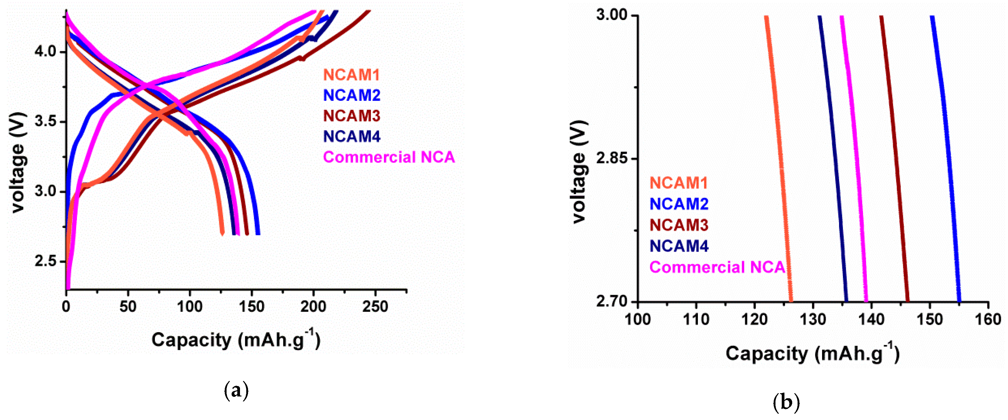
The initial charge–discharge curves of NCA cathode prepared using various precursor solution concentrations are plotted in
Figure 14. As can be seen, NCAM2 sample has initial specific discharge capacity of 155 mAh·g
−1 while NCAM3 has initial specific discharge capacity of 146 mAh·g
−1 of which both has higher capacity than that of commercial NCA. The highest capacity achieved by NCAM2 samples imply that 1.0 M is the optimum concentration of precursor solution which is consistent to the XRD result analysis.
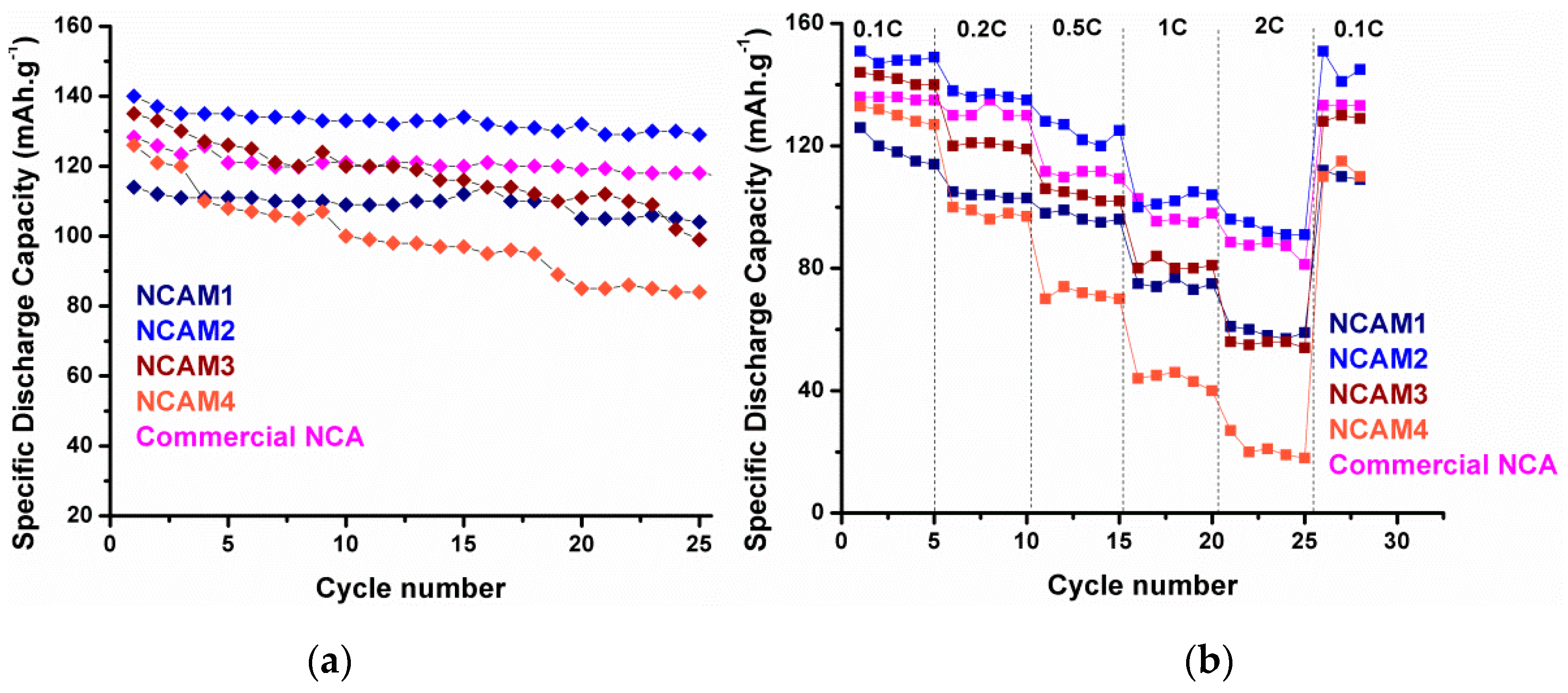
Figure 15a exhibits the cycle performance of NCAM1, NCAM2, NCAM3, and NCAM4. After 25 cycles, sample NCAM2 also has the highest capacity retention of 92%, while NCAM1, NCAM3, and NCAM4 have capacity retention of 91%, 75%, and 67%, respectively. Again, this cyclic performance results prove that the excellent stability of NCAM2 is attributed to good structural properties and morphology of the materials [
35]. The rate-ability curve plotted in
Figure 15b has the same tendency as the cycle behavior. High particle size of NCAM3 and NCAM4 caused poor rate performances which largely affected by Li ion diffusion during insertion and de-insertion process [
35].
3.5. Post Cycle Analysis
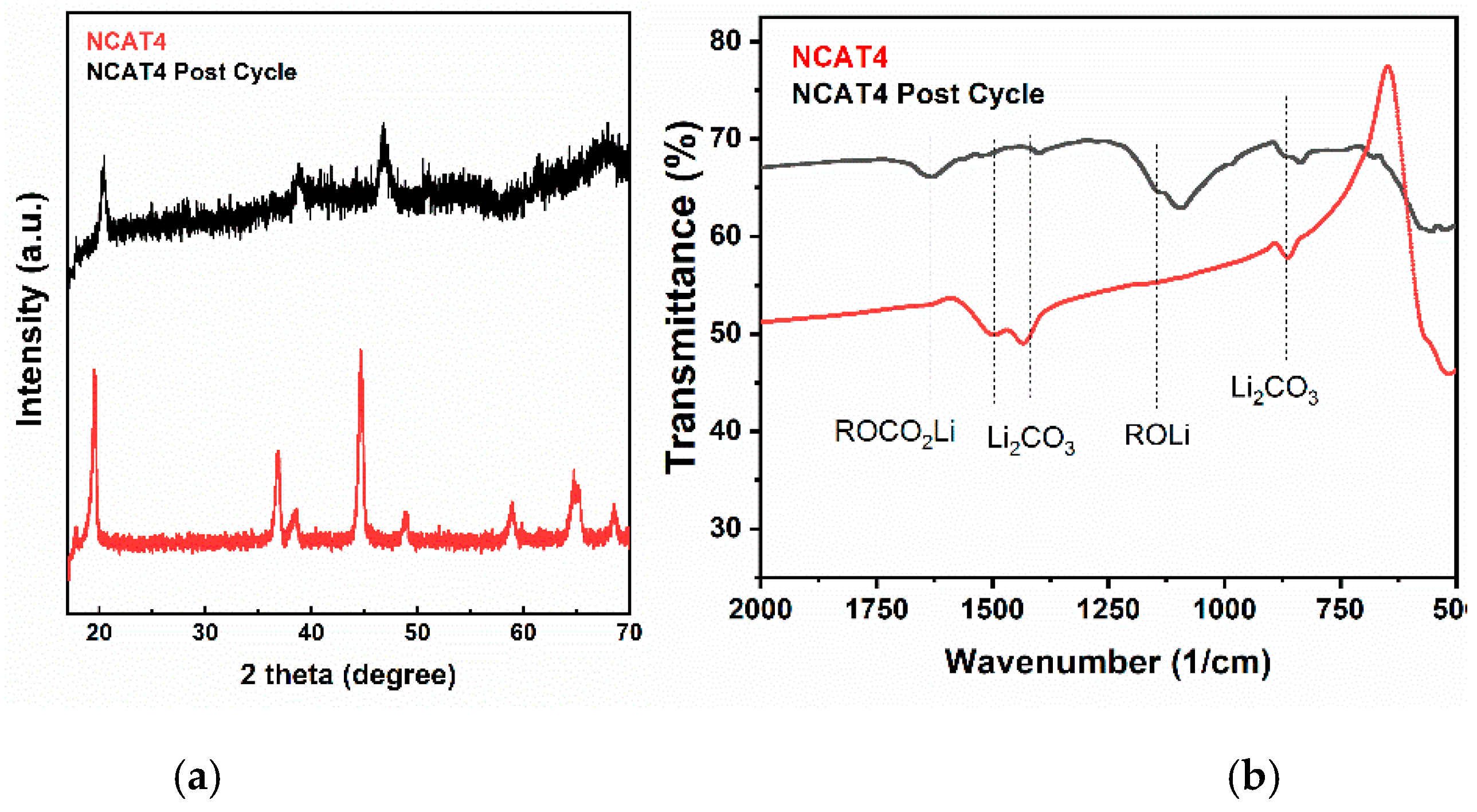
Figure 16 shows the post cycled NCAT4/NCAM2 sample characterization using XRD (
Figure 16a) and FTIR (
Figure 16b) with fresh NCAT4/NCAM2 sample as reference. The XRD data were obtained using Mini-diffractometer (MTI, California, CA, USA). The X-ray diffraction pattern of post cycled NCAT4/NCAM2 is different compare to the fresh sample. The post cycled sample has lower intensity and all of the peaks shifted to higher 2θ-angles after 50 cycles at 0.2 C which indicate decreased crystallinity and a contraction in the c-axis due to repeating insertion and de-insertion of Li-ion, respectively. In addition, high noise in the pattern may be caused by the presence of residual electrolyte and acetylene black in the powder. On the other hand, all of the peaks still can be indexed to a layered structure which shows that the structure of NCA is not fully damaged. Based on the FTIR spectra analysis, the presence of Li
2CO
3, ROCO
2Li, and ROLi on the surface of the sample can be attributed to side reactions between electrolyte and cathode occurred during charge and discharge, causing a capacity decrease [
22,
36].
Figure 17 displays the Energy Dispersive X-ray (EDX) spectra analysis of pre-cycled and post-cycled NCAT4/NCAM2 sample. The mass and molar composition of the samples are listed in
Table 5. The presence of carbon in fresh NCAT sample can be attributed to the presence of Li
2CO
3 on the surface due to reaction between excess Li with CO
2 in air. The molar Ni-Co-Al composition are close to the targeted value of 81.5:15:3.5. The post cycled sample has high amount of carbon due to PVDF and AB content. The existence of P and F confirm the presence residual LiPF
6 electrolyte. The molar Ni-Co-Al composition of post-cycled NCAT4 is 78.5:16.1:5.4, indicating a decrease of Ni content which may be caused by the dissolution of Ni by HF [
13,
37].
